EP3251606B1 - Retractor - Google Patents
Retractor Download PDFInfo
- Publication number
- EP3251606B1 EP3251606B1 EP15880062.3A EP15880062A EP3251606B1 EP 3251606 B1 EP3251606 B1 EP 3251606B1 EP 15880062 A EP15880062 A EP 15880062A EP 3251606 B1 EP3251606 B1 EP 3251606B1
- Authority
- EP
- European Patent Office
- Prior art keywords
- belt
- shaped body
- retractor
- surgical
- surgical incision
- Prior art date
- Legal status (The legal status is an assumption and is not a legal conclusion. Google has not performed a legal analysis and makes no representation as to the accuracy of the status listed.)
- Active
Links
Images





Classifications
-
- A—HUMAN NECESSITIES
- A61—MEDICAL OR VETERINARY SCIENCE; HYGIENE
- A61B—DIAGNOSIS; SURGERY; IDENTIFICATION
- A61B17/00—Surgical instruments, devices or methods
- A61B17/02—Surgical instruments, devices or methods for holding wounds open, e.g. retractors; Tractors
-
- A—HUMAN NECESSITIES
- A61—MEDICAL OR VETERINARY SCIENCE; HYGIENE
- A61B—DIAGNOSIS; SURGERY; IDENTIFICATION
- A61B17/00—Surgical instruments, devices or methods
- A61B17/02—Surgical instruments, devices or methods for holding wounds open, e.g. retractors; Tractors
- A61B17/0293—Surgical instruments, devices or methods for holding wounds open, e.g. retractors; Tractors with ring member to support retractor elements
-
- A—HUMAN NECESSITIES
- A61—MEDICAL OR VETERINARY SCIENCE; HYGIENE
- A61B—DIAGNOSIS; SURGERY; IDENTIFICATION
- A61B17/00—Surgical instruments, devices or methods
- A61B2017/00831—Material properties
- A61B2017/00862—Material properties elastic or resilient
-
- A—HUMAN NECESSITIES
- A61—MEDICAL OR VETERINARY SCIENCE; HYGIENE
- A61B—DIAGNOSIS; SURGERY; IDENTIFICATION
- A61B17/00—Surgical instruments, devices or methods
- A61B2017/00831—Material properties
- A61B2017/00884—Material properties enhancing wound closure
-
- A—HUMAN NECESSITIES
- A61—MEDICAL OR VETERINARY SCIENCE; HYGIENE
- A61B—DIAGNOSIS; SURGERY; IDENTIFICATION
- A61B17/00—Surgical instruments, devices or methods
- A61B2017/00982—General structural features
- A61B2017/00991—Telescopic means
-
- A—HUMAN NECESSITIES
- A61—MEDICAL OR VETERINARY SCIENCE; HYGIENE
- A61B—DIAGNOSIS; SURGERY; IDENTIFICATION
- A61B17/00—Surgical instruments, devices or methods
- A61B17/02—Surgical instruments, devices or methods for holding wounds open, e.g. retractors; Tractors
- A61B17/0218—Surgical instruments, devices or methods for holding wounds open, e.g. retractors; Tractors for minimally invasive surgery
- A61B2017/0225—Surgical instruments, devices or methods for holding wounds open, e.g. retractors; Tractors for minimally invasive surgery flexible, e.g. fabrics, meshes, or membranes
Definitions
- the present invention relates to a retractor for holding a surgical incision open and maintaining a surgical field during an operation.
- Further proposed methods include providing a retractor including in-body-side and out-body-side ring members fixed on both peripheral edges of the opening of a tubular flexible sleeve and bringing the outer surface of the flexible sleeve of the retractor into contact with the surgical incision site (see, for example, Patent Literature 3); and providing a retractor made of a rectangular elastic sheet, winding the retractor into a small-diameter roll with its beginning and terminal ends slidable relatively to each other, inserting the small-diameter roll into the surgical incision by hand, and then releasing the roll from hand so that the roll expands in diameter due to the elastic force to widen the surgical incision (see, for example, Patent Literature 4) (hereinafter, these methods will be referred to as "the method of holding the surgical incision open with an independent type retractor").
- Patent Literature 5 describes a mucosal dissection operation assisting tool for assisting a mucosal dissection operation by lifting a mucosal when a mucosal is dissected.
- US 2007/038032 A1 discloses a deformable elastic plate which is used as a retractor.
- the method of holding the surgical incision open with arm support type retractors can eliminate the need for surgical assistants to hold and pull the medical devices, and thus can reduce the labor costs as compared with the method of holding the surgical incision open by hand.
- the retractors form a relatively large system, which increases the retractor production costs and accordingly increases the operation costs.
- pole, arm, and other parts may become an encumbrance to the operator and reduce the workability, and will also make it impossible to flexibly change the surgical field depending on the surgical situation.
- the method of holding the surgical incision open with an independent type retractor can eliminate the need for assistants to hold and pull the medical devices and thus reduce the labor costs as compared with the method of holding the surgical incision open by hand.
- the retractor free of any additional part such as an arm or a pole will not become an encumbrance to the operator or reduce the workability in contrast to the arm support type retractor for holding the surgical incision open.
- the method of holding the surgical incision open with an independent type retractor configured as described in Patent Literature 4 may fail to maintain the desired surgical field, because the elastic force is used to expand the diameter of the roll and to widen the surgical incision, which may fail to produce the force necessary to hold the surgical incision open.
- an object of the present invention is to provide a retractor that makes it possible to reduce operation costs, is less likely to cause damage to surgical incision sites, do not reduce workability, and also makes it possible to easily maintain the desired surgical field, to change the surgical field depending on the surgical situation, and to widen or narrow the area of the surgical field depending on the surgical situation.
- the present invention as defined in claim 1 is directed to a retractor for holding a surgical incision open and maintaining a surgical field during an operation, the retractor including: a belt-shaped body made of a wire; and a connecting part that is provided at one end portion of the belt-shaped body and capable of being connected to another end portion or an intermediate portion of the belt-shaped body so that the belt-shaped body can be formed into a loop of a desired size, the retractor being so configured that when the belt-shaped body is formed into a loop, the outer surface of the belt-shaped body resists the force generated at the surgical incision and acting in such a direction as to close the surgical incision.
- the outer surface of the belt-shaped body looped with the connecting part resists the force acting in such a direction as to close the surgical incision, which eliminates the need for surgical assistants to pull and hold rod-shaped medical devices with hooked front ends.
- the retractor of the present invention has a simple structure including the belt-shaped body made of a wire; and the connecting part provided to allow the belt-shaped body to be formed into a loop. Therefore, the retractor of the present invention can be produced at a lower cost than the arm support type retractor for holding the surgical incision open.
- the belt-shaped body is made of a wire. Therefore, in contrast to the conventional independent type retractor for holding the surgical incision open, the retractor of the present invention can be used not only in a circular loop shape but also in an elliptical, oval, or any other shape to maintain the desired surgical field, and additionally, the belt-shaped body can also be deformed in the transverse direction, so that the retractor of the present invention can be deformed or displaced so as not to cause any damage to lower bones, muscles, blood vessels, or other sites.
- the belt-shaped body is a product obtained by pressurizing and plastically deforming a coil spring.
- the belt-shaped body formed by pressurizing and plastically deforming a coil spring maintains smooth surfaces (upper and lower surfaces and outer and inner surfaces) even when the loop size is changed. Therefore, the belt-shaped body will not cause any damage to patient's internal organs and other body parts or to operator's gloves.
- the belt-shaped body is more preferably a product obtained by pressurizing and plastically deforming a coil spring assembly that is obtained by inserting, into each other, a pair of left- and right-hand coil springs each having a pitch greater than its wire diameter.
- the belt-shaped body is formed by inserting a pair of left- and right-hand coil springs into each other to form a coil spring assembly and then pressuring and plastically deforming the coil spring assembly.
- a lightweight, less stiff wire is used for ease of handling and other purposes, it is easy to form the belt-shaped body with sufficient stiffness required to resist the force acting in such a direction as to close the surgical incision and required to hold the surgical incision open.
- FIG. 3 is not intended to limit the shape or structure of the connecting part B and that the connecting part B may have any other shape or structure that allows one end portion of the belt-shaped body A to be connected to and disconnected from another end portion or an intermediate portion of the belt-shaped body A.
- the belt-shaped body A used to form the retractor 1 is produced using a pair of left- and right-hand coil springs 2 and 3.
- the belt-shaped body A shown in the front view of FIG. 7 may also be used, which is produced by pressurizing and plastically deforming one of left- and right-hand coil springs.
- the retractor 1 has a simple structure including the belt-shaped body A made of a wire; and the connecting part B provided to allow the belt-shaped body A to be formed into a loop. Therefore, the retractor 1 can be produced at a lower cost than the arm support type retractor for holding the surgical incision open.
- the connecting part B allows the belt-shaped body A to be formed into a loop of a desired size. This makes it possible to easily maintain the desired surgical field, as compared with the method of holding the surgical incision open with a conventional independent type retractor. This also makes it possible to easily change the surgical field or easily widen or narrow the area of the surgical field, depending on the surgical situation.
- the coil spring has a pitch p greater than its wire diameter d
- a gap is formed between the turns.
- This feature makes easy the process of forming the belt-shaped body by pressurization and plastic deformation and also makes the looped retractor 1 easily deformable. Therefore, this feature makes it easy to change the surgical field, depending on the surgical situation, and to avoid any damage to lower bones, muscles, blood vessels, or other sites.
- the belt-shaped body A made of a wire can provide a high unoccupied space ratio, so that relatively large gaps E (see FIG. 1 ) can be formed in the belt-shaped body A formed into a loop. The gaps E make it easy to see the surgical site and its surroundings during the operation, so that the workability can be improved.
Landscapes
- Health & Medical Sciences (AREA)
- Life Sciences & Earth Sciences (AREA)
- Surgery (AREA)
- Heart & Thoracic Surgery (AREA)
- Engineering & Computer Science (AREA)
- Biomedical Technology (AREA)
- Nuclear Medicine, Radiotherapy & Molecular Imaging (AREA)
- Medical Informatics (AREA)
- Molecular Biology (AREA)
- Animal Behavior & Ethology (AREA)
- General Health & Medical Sciences (AREA)
- Public Health (AREA)
- Veterinary Medicine (AREA)
- Surgical Instruments (AREA)
Description
- The present invention relates to a retractor for holding a surgical incision open and maintaining a surgical field during an operation.
- During a manual operation on an affected area, the surgical incision must be held open so that the surgical field can be maintained and the surgeon can reach the affected area, because the force generated at the surgical incision acts in such a direction as to close the surgical incision. Maintaining the surgical field in a good condition makes it possible, for example, to reduce the operation time, to improve the safety, and to reduce fatigue of the operator (surgeon).
- In a common method for holding a surgical incision open, surgical assistants hold rod-shaped medical devices with hooked front ends (see, for example, Non Patent Literature 1) and pull, by hand, the medical devices with the front ends hooked on the surgical incision site (hereinafter, this method will be referred to as "the method of holding the surgical incision open by hand").
- Other methods include using retractors whose front ends are hooked on the surgical incision site and which are held with an articulated arm extending from a pole (see, for example,
Patent Literatures 1 and 2); and using retractors whose front ends are hooked on the surgical incision site and which are held with a support ring, an arm, and a pole (see, for example,Patent Literature 2 and Non Patent Literature 3) (hereinafter, these methods will be referred to as "the method of holding the surgical incision open with arm support type retractors"). - Further proposed methods include providing a retractor including in-body-side and out-body-side ring members fixed on both peripheral edges of the opening of a tubular flexible sleeve and bringing the outer surface of the flexible sleeve of the retractor into contact with the surgical incision site (see, for example, Patent Literature 3); and providing a retractor made of a rectangular elastic sheet, winding the retractor into a small-diameter roll with its beginning and terminal ends slidable relatively to each other, inserting the small-diameter roll into the surgical incision by hand, and then releasing the roll from hand so that the roll expands in diameter due to the elastic force to widen the surgical incision (see, for example, Patent Literature 4) (hereinafter, these methods will be referred to as "the method of holding the surgical incision open with an independent type retractor").
-
Patent Literature 5 describes a mucosal dissection operation assisting tool for assisting a mucosal dissection operation by lifting a mucosal when a mucosal is dissected. -
- Patent Literature 1:
Japanese Unexamined Utility Model Application Publication No. H06-55607 - Patent Literature 2:
Japanese Unexamined Patent Application Publication No. H07-239727 - Patent Literature 3:
Japanese Unexamined Patent Application Publication No. 2013-55993 - Patent Literature 4:
Japanese Translation of PCT International Application Publication No. 2007-82674 - Patent Literature 5:
WO 2009/034922 A1 . -
US 2007/038032 A1 discloses a deformable elastic plate which is used as a retractor. -
- Non Patent Literature 1: "Koppel Single Hook/Koppel Double Hook" list, Tanaka Medical Instrument Co., Ltd., Internet URL: http://www.e-tanaka.co.jp/products/display_detail/23-18-G_19-G
- Non-Patent Literature 2: "Octopus Universal Retractor" list, Yufu Itonaga Co., Ltd., November 2012, Internet URL: http://www.yufu.co.jp/pdf/octopus.pdf
- Non-Patent Literature 3: "Table Mounted Retractor System" list, Solve Corporation, Internet URL: http://www.solve-net.com/MakerBusiness/Surgical/img_Mediflex/RetractorProducts.pd f
- In the method of holding the surgical incision open by hand, a required number of surgical assistants have to hold and pull, by hand, a required number of the medical devices with the front ends hooked on the surgical incision site. Therefore, this method will be more likely to cause damage to the surgical incision site, on which the front ends of the medical devices hooked, and can place a relatively large burden on the surgical assistants and increase the operation costs due to the assistant labor costs.
- The method of holding the surgical incision open with arm support type retractors can eliminate the need for surgical assistants to hold and pull the medical devices, and thus can reduce the labor costs as compared with the method of holding the surgical incision open by hand.
- However, the method, in which the retractors are pulled while their front ends are hooked on the surgical incision site, will also be more likely to cause damage to the surgical incision site.
- In addition, the retractors form a relatively large system, which increases the retractor production costs and accordingly increases the operation costs.
- In addition, the pole, arm, and other parts may become an encumbrance to the operator and reduce the workability, and will also make it impossible to flexibly change the surgical field depending on the surgical situation.
- The method of holding the surgical incision open with an independent type retractor can eliminate the need for assistants to hold and pull the medical devices and thus reduce the labor costs as compared with the method of holding the surgical incision open by hand. In addition, the retractor free of any additional part such as an arm or a pole will not become an encumbrance to the operator or reduce the workability in contrast to the arm support type retractor for holding the surgical incision open.
- In that method, however, the surgical field cannot be changed depending on the surgical situation, and the area of the surgical field cannot be widened or narrowed depending on the surgical situation.
- In addition, the method of holding the surgical incision open with an independent type retractor configured as described in
Patent Literature 3 requires a laborious process to put the retractor in place in such a manner that the outer surface of the flexible sleeve is in the contact with the surgical incision site. - In addition, the method of holding the surgical incision open with an independent type retractor configured as described in
Patent Literature 4 may fail to maintain the desired surgical field, because the elastic force is used to expand the diameter of the roll and to widen the surgical incision, which may fail to produce the force necessary to hold the surgical incision open. - In view of the above circumstances, an object of the present invention is to provide a retractor that makes it possible to reduce operation costs, is less likely to cause damage to surgical incision sites, do not reduce workability, and also makes it possible to easily maintain the desired surgical field, to change the surgical field depending on the surgical situation, and to widen or narrow the area of the surgical field depending on the surgical situation.
- To solve the above problems, the present invention as defined in
claim 1 is directed to a retractor for holding a surgical incision open and maintaining a surgical field during an operation, the retractor including: a belt-shaped body made of a wire; and a connecting part that is provided at one end portion of the belt-shaped body and capable of being connected to another end portion or an intermediate portion of the belt-shaped body so that the belt-shaped body can be formed into a loop of a desired size, the retractor being so configured that when the belt-shaped body is formed into a loop, the outer surface of the belt-shaped body resists the force generated at the surgical incision and acting in such a direction as to close the surgical incision. - According to these features, the outer surface of the belt-shaped body looped with the connecting part resists the force acting in such a direction as to close the surgical incision, which eliminates the need for surgical assistants to pull and hold rod-shaped medical devices with hooked front ends. This makes it possible to reduce labor costs, as compared with the method of holding the surgical incision open by hand, and to make immediate intervention even when a temporary or emergency operation needs to be performed by only one doctor, for example, in accident and emergency situations.
- Moreover, when the retractor of the present invention is used, the surgical incision site does not need to be hooked on the front ends of the rod-shaped medical devices or any other retractors or pulled with the rod-shaped medical devices or any other retractors, so that the surgical incision site will not be damaged in contrast to the method of holding the surgical incision open by hand and the method of holding the surgical incision open with arm support type retractors.
- Furthermore, the retractor of the present invention is free of any obstructive part such as an arm or a pole and thus will not reduce workability in contrast to the arm support type retractor for holding the surgical incision open.
- In addition, the retractor of the present invention has a simple structure including the belt-shaped body made of a wire; and the connecting part provided to allow the belt-shaped body to be formed into a loop. Therefore, the retractor of the present invention can be produced at a lower cost than the arm support type retractor for holding the surgical incision open.
- In addition, the connecting part allows the belt-shaped body to be formed into a loop of a desired size. This makes it possible to easily maintain the desired surgical field, as compared with the method of holding the surgical incision open with a conventional independent type retractor. This also makes it possible to easily change the surgical field or easily widen or narrow the area of the surgical field, depending on the surgical situation.
- In addition, the belt-shaped body is made of a wire. Therefore, in contrast to the conventional independent type retractor for holding the surgical incision open, the retractor of the present invention can be used not only in a circular loop shape but also in an elliptical, oval, or any other shape to maintain the desired surgical field, and additionally, the belt-shaped body can also be deformed in the transverse direction, so that the retractor of the present invention can be deformed or displaced so as not to cause any damage to lower bones, muscles, blood vessels, or other sites.
- In the retractor of the present invention, the belt-shaped body is a product obtained by pressurizing and plastically deforming a coil spring.
- According to this feature, the belt-shaped body made of a wire can be produced by subjecting a coil spring, which is easily formed using a spring coiling machine (coiling machine) or other means, to pressurization and plastic deformation, in which, for example, the coil spring is passed between rolls, so that the retractor of the present invention can be produced at a lower cost.
- In addition, the belt-shaped body formed by pressurizing and plastically deforming a coil spring maintains smooth surfaces (upper and lower surfaces and outer and inner surfaces) even when the loop size is changed. Therefore, the belt-shaped body will not cause any damage to patient's internal organs and other body parts or to operator's gloves.
- In addition, the coil spring preferably has a pitch greater than its wire diameter.
- According to this feature, a gap is formed between the turns of the coil. This makes easy the process of forming the belt-shaped body by pressurization and plastic deformation and also makes the looped retractor easily deformable. Therefore, this feature makes it easy to change the surgical field, depending on the surgical situation, and to avoid any damage to lower bones, muscles, blood vessels, or other sites.
- In addition, the belt-shaped body made of a wire can provide a high unoccupied space ratio, so that relatively large gaps can be formed in belt-shaped body formed into a loop. The gaps make it easy to see the surgical site and its surroundings during the operation, so that the workability can be improved.
- In addition, the belt-shaped body is more preferably a product obtained by pressurizing and plastically deforming a coil spring assembly that is obtained by inserting, into each other, a pair of left- and right-hand coil springs each having a pitch greater than its wire diameter.
- According to this feature, the belt-shaped body is formed by inserting a pair of left- and right-hand coil springs into each other to form a coil spring assembly and then pressuring and plastically deforming the coil spring assembly. In this case, therefore, even when a lightweight, less stiff wire is used for ease of handling and other purposes, it is easy to form the belt-shaped body with sufficient stiffness required to resist the force acting in such a direction as to close the surgical incision and required to hold the surgical incision open.
- In addition, the use of a pair of left- and right-hand coil springs makes easy the process of forming the coil spring assembly by insertion into each other and also makes it possible to suppress the increase in production cost because the pair of coil springs can be easily produced using a spring coiling machine (coiling machine) or other means.
- In addition, the retractor more preferably further includes a plurality of hooks that are provided apart from one another in a circumferential direction on the outer surface of the belt-shaped body formed into a loop, the hooks being so provided that the skin around the surgical incision can be held on the hooks.
- According to this feature, the skin around the surgical incision can be reliably held on the hooks so that the surgical incision can be prevented from shifting. This makes it possible to prevent unintentional movement of the surgical incision, which might otherwise interfere with the operation, to prevent surgical instruments or other tools from coming into incidental contact with and injuring non-affected areas, and to efficiently perform the operation while the surgical field is surely maintained.
- In addition, the belt-shaped body formed into a loop more preferably has an outer surface that has been roughened to have an increased friction coefficient.
- According to this feature, the outer surface of the belt-shaped body has been roughened to have an increased friction coefficient, which provides an anti-skid function to prevent the surgical incision from shifting when the skin around the surgical incision comes into contact with the outer surface of the belt-shaped body. This makes it possible to prevent unintentional movement of the surgical incision, which might otherwise interfere with the operation, to prevent surgical instruments or other tools from coming into incidental contact with and injuring non-affected areas, and to efficiently perform the operation while the surgical field is surely maintained.
- As described above, the retractor according to the present invention has, for example, the following significantly advantageous effects.
- (1) The outer surface of the belt-shaped body looped with the connecting part resists the force acting in such a direction as to close the surgical incision, which makes it possible to reduce labor costs, to make immediate intervention even when a operation needs to be performed by only one doctor, for example, in accident and emergency situations, and to prevent any damage to the surgical incision site.
- (2) The retractor is free of any obstructive part such as an arm or a pole and thus will not reduce workability.
- (3) The retractor can be produced at a lower cost because it has a simple structure including the belt-shaped body made of a wire; and the connecting part provided to allow the belt-shaped body to be formed into a loop.
- (4) The connecting part allows the belt-shaped body to be formed into a loop of a desired size, which makes it possible to easily maintain the desired surgical field and to easily change the surgical field or easily widen or narrow the area of the surgical field, depending on the surgical situation.
- (5) The belt-shaped body made of a wire can be deformed to maintain any desired surgical field and can also be deformed in the transverse direction, so that the retractor can be deformed or displaced so as not to cause any damage to lower bones, muscles, blood vessels, or other sites.
- (6) The belt-shaped body made of a wire can be produced by pressurizing and plastically deforming a coil spring, which makes it possible to reduce the production cost and allows the belt-shaped body to maintain smooth surfaces (upper and lower surfaces and outer and inner surfaces) even when the loop size is changed, so that the belt-shaped body will not cause any damage to patient's internal organs and other body parts or to operator's gloves.
- (7) The use of a coil spring with a pitch greater than its wire diameter makes easy the process of forming the belt-shaped body and also makes it easy to deform the looped detractor, which allows easy change of the surgical field depending on the surgical situation and also allows easy avoidance of damage to lower bones, muscles, blood vessels, or other sites, and in this case, relatively large gaps formed in the belt-shaped body formed into a loop make it easy to see the surgical site and its surroundings during the operation, so that the workability can be improved.
- (8) In the case where the belt-shaped body made of a wire is produced by pressuring and plastically deforming a coil spring assembly that is formed by inserting, into each other, a pair of left- and right-hand coil springs each with the pitch greater than the wire diameter, it is easy to form the belt-shaped body with sufficient stiffness required to resist the force acting in such a direction as to close the surgical incision and required to hold the surgical incision open, even when a lightweight, less stiff wire is used for ease of handling and other purposes, and the increase in production cost can also be suppressed.
- (9) When the retractor further includes a plurality of hooks that are provided apart from one another in a circumferential direction on the outer surface of the belt-shaped body formed into a loop and also so provided that the skin around the surgical incision can be held on the hooks, or when the belt-shaped body has an outer surface that has been roughened to have an increased friction coefficient, the retractor can prevent the surgical incision from shifting, which makes it possible to prevent unintentional movement of the surgical incision, which might otherwise interfere with the operation, to prevent surgical instruments or other tools from coming into incidental contact with and injuring non-affected areas, and to efficiently perform the operation while the surgical field is surely maintained.
-
-
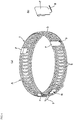
FIG. 1 is a perspective view showing an example of how to use a retractor according to an embodiment of the present invention looped with a connecting part. -
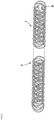
FIG. 2 is a front view showing the retractor according to an embodiment of the present invention extended in a belt shape. -
FIG. 3 is an enlarged perspective view of a main part at and around a connecting part. -
FIG. 4(a) is a perspective view of left- and right-hand coil springs, andFIG. 4(b) is a perspective view of a coil spring assembly. -
FIG. 5 is a schematic diagram showing the process of forming a coil spring assembly into a belt-shaped body by plastic deformation in which the coil spring assembly is passed between a pair of rolls. -
FIG. 6(a) is a perspective view showing a retractor provided with hooks on which the skin around a surgical incision is to be held, andFIG. 6(b) is a perspective view of the hook. -
FIG. 7 is a front view showing a retractor according to a modified embodiment extended in a belt shape. -
FIG. 8 is a front view showing a retractor according to another modified embodiment extended in a belt shape. - Next, embodiments of the present invention will be described in detail with reference to the attached drawings. It will be understood that the present invention is not limited to the embodiments shown in the attached drawings and encompasses all possible embodiments satisfying the requirements recited in the claims.
-
FIG. 1 is a perspective view showing an example of how to use aretractor 1 according to an embodiment of the present invention. The use does not form part of the invention.FIG. 2 is a front view showing theretractor 1 extended in a belt shape. As shown inFIGS. 1 and2 , theretractor 1, which is for holding a surgical incision open and maintaining a surgical field during an operation, includes a belt-shaped body A made of a wire; and a connecting part B that is provided at one end portion of the belt-shaped body A and capable of being connected to another end portion or an intermediate portion of the belt-shaped body A so that the belt-shaped body A can be formed into a loop of a desired size. In addition, theretractor 1 is so configured that when the belt-shaped body A is formed into a loop as shown inFIG. 1 , the outer surface D of the belt-shaped body A resists the force generated at the surgical incision and acting in such a direction as to close the surgical incision. - In this embodiment, the wire used to form the belt-shaped body A is a wire of a metal such as pure titanium, a titanium alloy, an aluminum alloy, a copper alloy, or stainless steel, a wire of a super-elastic alloy such as a nickel-titanium alloy or a copper-based alloy, or a wire of synthetic resin such as polyethylene terephthalate (PET) resin, polyamide (PA) resin, or polyether ether ketone (PEEK) resin (optionally containing reinforcing fibers such as glass fibers or carbon fibers). The cross-sectional shape of the wire is circular, as in this embodiment, or polygonal.
- The connecting part B is made of a metal such as stainless steel or synthetic resin such as PET resin.
- As shown in the main part enlarged perspective view of
FIG. 3 , the connecting part B provided at one end portion of the belt-shaped body A has ahook 4. Therefore, the belt-shaped body A can be easily formed into a loop of a desired size by hooking thehook 4 on another end portion or an intermediate portion of the wire of belt-shaped body A, and the size of the loop can also be easily changed by hooking thehook 4 on the wire. - It will be understood that
FIG. 3 is not intended to limit the shape or structure of the connecting part B and that the connecting part B may have any other shape or structure that allows one end portion of the belt-shaped body A to be connected to and disconnected from another end portion or an intermediate portion of the belt-shaped body A. - Next, an example of a method for producing the belt-shaped body A of the
retractor 1 will be described. - First, as shown in the perspective view of
FIG. 4(a) , compression springs with a specific wire diameter d, a specific pitch p, a specific outer diameter, and a specific number of turns are formed using a spring coiling machine (coiling machine) or other means, so that a pair of left- and right-hand coil springs - Subsequently, as shown in the perspective view of
FIG. 4(b) , the left- and right-hand coil springs coil springs - Subsequently, as shown in the schematic diagram of
FIG. 5 , the coil spring assembly C is plastically deformed by being passed between a pair of rolls R1 and R2 to form the belt-shaped body A. - Alternatively, the process of plastically deforming the coil spring assembly C to form the belt-shaped body A may be performed using, for example, a press mold instead of the pair of rolls R1 and R2 shown in
FIG. 5 . However, the production cost can be reduced using the pair of rolls R1 and R2. - Subsequently, the connecting part B is attached to one end portion of the belt-shaped body A so that the
retractor 1 is completed. - As shown in the perspective views of
FIGS. 6(a) and 6(b) , the loop of the belt-shaped body A of the retractor 1 (seeFIGS. 1 and2 ) completed as described above may be provided with a plurality of hooking parts F (three hooking parts F in this embodiment), which are spaced in the circumferential direction and on which the skin around a surgical incision is to be held. In this embodiment, the hooking parts F are made of a metal such as stainless steel or synthetic resin such as PET resin. - According to this feature, the outer surface D of the belt-shaped body A formed into a loop is provided with
hooks 5 protruding outside in the radial direction from the hooking parts F spaced in the circumferential direction. Therefore, the skin around the surgical incision can be reliably held on thehooks 5 so that the surgical incision can be prevented from shifting. This makes it possible to prevent unintentional movement of the surgical incision, which might otherwise interfere with the operation, to prevent surgical instruments or other tools from coming into incidental contact with and injuring non-affected areas, and to efficiently perform the operation while the surgical field is surely maintained. - Alternatively, without the hooking parts F shown in
FIG. 6(a) , the friction coefficient of the outer surface D may be increased by, for example, shot blasting in which the outer surface D of the loop of the belt-shaped body A of theretractor 1 shown inFIG. 1 is roughened by allowing particles called projectiles to collide with the outer surface D. - This feature also makes it possible to prevent displacement of the surgical incision and thus makes it possible to prevent unintentional movement of the surgical incision, which might otherwise interfere with the operation, to prevent surgical instruments or other tools from coming into incidental contact with and injuring non-affected areas, and to efficiently perform the operation while the surgical field is surely maintained.
- The above description has shown a case where the
coil springs - The above description has also shown a case where the belt-shaped body A used to form the
retractor 1 is produced using a pair of left- and right-hand coil springs FIG. 7 may also be used, which is produced by pressurizing and plastically deforming one of left- and right-hand coil springs. - In addition, the belt-shaped body A used to form the
retractor 1 may also be a belt-shaped body A having a repeating structure as shown in the front view ofFIG. 8 , which is formed by extending and shaping a wire in a plane instead of pressuring and plastically deforming a coil spring. - When the
retractor 1 with the features described above is used, the outer surface D of the belt-shaped body A looped with the connecting part B resists the force acting in such a direction as to close the surgical incision. Therefore, the use of theretractor 1 eliminates the need for surgical assistants to hold and pull rod-shaped medical devices with a hooked front end. This makes it possible to reduce labor costs, as compared with the method of holding the surgical incision open by hand, and to make immediate intervention even when a temporary or emergency operation needs to be performed by only one doctor, for example, in accident and emergency situations. - Moreover, when the
retractor 1 is used, the surgical incision site does not need to be hooked on the front ends of the rod-shaped medical devices or any other retractors or pulled with the rod-shaped medical devices or any other retractors, so that the surgical incision site will not be damaged in contrast to the method of holding the surgical incision open by hand and the method of holding the surgical incision open with arm support type retractors. - Furthermore, the
retractor 1 is free of any obstructive part such as an arm or a pole and thus will not reduce workability in contrast to the arm support type retractor for holding the surgical incision open. - In addition, the
retractor 1 has a simple structure including the belt-shaped body A made of a wire; and the connecting part B provided to allow the belt-shaped body A to be formed into a loop. Therefore, theretractor 1 can be produced at a lower cost than the arm support type retractor for holding the surgical incision open. - In addition, the connecting part B allows the belt-shaped body A to be formed into a loop of a desired size. This makes it possible to easily maintain the desired surgical field, as compared with the method of holding the surgical incision open with a conventional independent type retractor. This also makes it possible to easily change the surgical field or easily widen or narrow the area of the surgical field, depending on the surgical situation.
- In addition, the belt-shaped body A is made of a wire. Therefore, in contrast to the conventional independent type retractor for holding the surgical incision open, the
retractor 1 can be used not only in a circular loop shape but also in an elliptical, oval, or any other shape to maintain the desired surgical field, and additionally, the belt-shaped body A can also be deformed in the transverse direction, so that theretractor 1 can be deformed or displaced so as not to cause any damage to lower bones, muscles, blood vessels, or other sites. - In addition, the belt-shaped body A is produced by pressurizing and plastically deforming a coil spring. In this case, the belt-shaped body A made of a wire can be produced by subjecting a coil spring, which is easily formed using a spring coiling machine (coiling machine) or other means, to pressurization and plastic deformation, in which, for example, the coil spring is passed between rolls, so that the
retractor 1 can be produced at a lower cost. - In addition, the belt-shaped body A formed by pressurizing and plastically deforming a coil spring maintains smooth surfaces (upper and lower surfaces and outer and inner surfaces) even when the loop size is changed. Therefore, the belt-shaped body A will not cause any damage to patient's internal organs and other body parts or to operator's gloves.
- In addition, when the coil spring has a pitch p greater than its wire diameter d, a gap is formed between the turns. This feature makes easy the process of forming the belt-shaped body by pressurization and plastic deformation and also makes the looped
retractor 1 easily deformable. Therefore, this feature makes it easy to change the surgical field, depending on the surgical situation, and to avoid any damage to lower bones, muscles, blood vessels, or other sites. In addition, the belt-shaped body A made of a wire can provide a high unoccupied space ratio, so that relatively large gaps E (seeFIG. 1 ) can be formed in the belt-shaped body A formed into a loop. The gaps E make it easy to see the surgical site and its surroundings during the operation, so that the workability can be improved. - In addition, the belt-shaped body A can be formed by inserting, into each other, a pair of left- and right-
hand coil springs - In addition, the use of a pair of left- and right-
hand coil springs coil springs -
- 1
- Retractor
- 2
- Lift-hand coil spring
- 3
- Right-hand coil spring
- 4,5
- Hook
- A
- Belt-shaped body
- B
- Connecting part
- C
- Coil spring assembly
- D
- Outer surface of belt-shaped body formed into a loop
- d
- Wire diameter
- E
- Gap
- F
- Hooking part
- p
- Pitch
- R1, R2
- Roll
Claims (5)
- A retractor (1) for holding a surgical incision open and maintaining a surgical field during an operation, the retractor (1) comprising:a belt-shaped body (A) made of a wire obtained by pressurizing and plastically deforming a coil spring (2, 3); anda connecting part (B) that is provided at one end portion of the belt-shaped body (A) and capable of being connected to another end portion or an intermediate portion of the belt-shaped body (A) so that the belt-shaped body (A) can be formed into a loop of a desired size,the retractor (1) being so configured that when the belt-shaped body (A) is formed into a loop, an outer surface (D) of the belt-shaped body (A) resists a force generated at the surgical incision and acting in such a direction as to close the surgical incision.
- The retractor (1) according to claim 1, wherein the coil spring (2, 3) has a pitch (p) greater than a wire diameter (d).
- The retractor (1) according to claim 1, wherein the belt-shaped body (A) is a product obtained by pressurizing and plastically deforming a coil spring assembly (C) that is obtained by inserting, into each other, a pair of left- and right-hand coil springs (2, 3) each having a pitch (p) greater than a wire diameter (d).
- The retractor (1) according to any one of claims 1 to 3, further comprising a plurality of hooks (5) that are provided apart from one another in a circumferential direction on an outer surface (D) of the belt-shaped body (A) formed into a loop, the hooks being so provided that a skin around the surgical incision can be held on the hooks.
- The retractor (1) according to any one of claims I to 3, wherein the belt-shaped body (A) formed into a loop has an outer surface (D) that has been roughened to have an increased friction coefficient.
Applications Claiming Priority (2)
| Application Number | Priority Date | Filing Date | Title |
|---|---|---|---|
| JP2015015622A JP6292141B2 (en) | 2015-01-29 | 2015-01-29 | Retractor |
| PCT/JP2015/079045 WO2016121169A1 (en) | 2015-01-29 | 2015-10-14 | Retractor |
Publications (3)
| Publication Number | Publication Date |
|---|---|
| EP3251606A1 EP3251606A1 (en) | 2017-12-06 |
| EP3251606A4 EP3251606A4 (en) | 2018-11-21 |
| EP3251606B1 true EP3251606B1 (en) | 2021-08-11 |
Family
ID=56542808
Family Applications (1)
| Application Number | Title | Priority Date | Filing Date |
|---|---|---|---|
| EP15880062.3A Active EP3251606B1 (en) | 2015-01-29 | 2015-10-14 | Retractor |
Country Status (6)
| Country | Link |
|---|---|
| US (1) | US10335132B2 (en) |
| EP (1) | EP3251606B1 (en) |
| JP (1) | JP6292141B2 (en) |
| KR (1) | KR102315793B1 (en) |
| CN (1) | CN107530071B (en) |
| WO (1) | WO2016121169A1 (en) |
Families Citing this family (6)
| Publication number | Priority date | Publication date | Assignee | Title |
|---|---|---|---|---|
| JP1533771S (en) * | 2015-02-23 | 2015-09-28 | ||
| CN107753073B (en) * | 2017-12-04 | 2024-04-05 | 黄河科技学院 | Quantitative opening device for clinical operation wound |
| CN108836412A (en) * | 2018-07-09 | 2018-11-20 | 吴飞 | A kind of operation retractor |
| CN109330642B (en) * | 2018-08-03 | 2020-05-01 | 云南靖创液态金属热控技术研发有限公司 | Auxiliary stretching device for endoscopic surgery |
| CN113693650A (en) * | 2021-08-31 | 2021-11-26 | 温贺新 | A retraction exposure device for hernia |
| CN117398146B (en) * | 2023-08-08 | 2024-08-02 | 盐城荣星制绳有限公司 | Medical spring rope and production and processing device thereof |
Family Cites Families (21)
| Publication number | Priority date | Publication date | Assignee | Title |
|---|---|---|---|---|
| JPS60184440A (en) * | 1984-03-01 | 1985-09-19 | Manabu Kiuchi | Mesh band |
| RU2033755C1 (en) * | 1986-07-17 | 1995-04-30 | Дамбаев Георгий Цыренович | Hollow organs space restrictor |
| JP2778372B2 (en) | 1992-08-11 | 1998-07-23 | 住友電装株式会社 | Tube forming apparatus and tube coating method |
| US5375481A (en) | 1993-11-12 | 1994-12-27 | Codman & Shurtleff, Inc. | Multi-position ratchet mechanism |
| US7559893B2 (en) * | 1998-12-01 | 2009-07-14 | Atropos Limited | Wound retractor device |
| DE10001695A1 (en) * | 2000-01-18 | 2001-02-08 | Dieter Pommerrenig | Device for spreading an operation access wound comprises two hinged oval-curved spring strips which are pressable together and insertable into an operation access wound |
| US7052454B2 (en) * | 2001-10-20 | 2006-05-30 | Applied Medical Resources Corporation | Sealed surgical access device |
| WO2003034908A2 (en) * | 2001-10-20 | 2003-05-01 | Applied Medical Resources Corporation | Sealed surgical access device |
| US6723044B2 (en) * | 2002-03-14 | 2004-04-20 | Apple Medical Corporation | Abdominal retractor |
| JP2006304819A (en) * | 2005-04-26 | 2006-11-09 | Junji Imanishi | Retractor |
| EP1752106A1 (en) * | 2005-08-11 | 2007-02-14 | Cardio Life Research S.A. | Surgical retractor |
| JP2007082674A (en) * | 2005-09-21 | 2007-04-05 | Junji Imanishi | Medical dilator |
| WO2007083305A2 (en) * | 2006-01-17 | 2007-07-26 | Ez Surgical Ltd. | Access enabling device for surgical procedures |
| US8323296B2 (en) * | 2007-03-15 | 2012-12-04 | Boris Malyugin | Ring used in a small pupil phacoemulsification procedure |
| JP5047297B2 (en) * | 2007-09-13 | 2012-10-10 | 信行 櫻澤 | Mucosal dissection aid |
| WO2009110863A1 (en) * | 2008-03-06 | 2009-09-11 | Sorensen Bradford T | Childbirth labor reduction device |
| EP2389220A4 (en) * | 2009-01-23 | 2017-09-13 | Intersect ENT, Inc. | Devices and methods for dilating tissues |
| US8251889B2 (en) * | 2009-02-25 | 2012-08-28 | Mis Solutions, Inc. | Apparatus and method for intra-abdominally moving a first internal organ to a position away from a second internal organ and then holding the first internal organ in the position without manual input |
| JP6005143B2 (en) | 2011-05-10 | 2016-10-12 | アプライド メディカル リソーシーズ コーポレイション | Retractor |
| EP2731506A1 (en) * | 2011-07-13 | 2014-05-21 | Cook Medical Technologies LLC | Foldable surgical retractor |
| JP5798417B2 (en) * | 2011-09-07 | 2015-10-21 | 株式会社トップ | Retractor |
-
2015
- 2015-01-29 JP JP2015015622A patent/JP6292141B2/en active Active
- 2015-10-14 EP EP15880062.3A patent/EP3251606B1/en active Active
- 2015-10-14 US US15/545,838 patent/US10335132B2/en active Active
- 2015-10-14 WO PCT/JP2015/079045 patent/WO2016121169A1/en not_active Ceased
- 2015-10-14 KR KR1020177024192A patent/KR102315793B1/en active Active
- 2015-10-14 CN CN201580074857.0A patent/CN107530071B/en active Active
Also Published As
| Publication number | Publication date |
|---|---|
| US10335132B2 (en) | 2019-07-02 |
| CN107530071B (en) | 2020-05-22 |
| WO2016121169A1 (en) | 2016-08-04 |
| JP6292141B2 (en) | 2018-03-14 |
| US20180000474A1 (en) | 2018-01-04 |
| KR20170134338A (en) | 2017-12-06 |
| EP3251606A4 (en) | 2018-11-21 |
| CN107530071A (en) | 2018-01-02 |
| KR102315793B1 (en) | 2021-10-20 |
| JP2016137218A (en) | 2016-08-04 |
| EP3251606A1 (en) | 2017-12-06 |
Similar Documents
| Publication | Publication Date | Title |
|---|---|---|
| US10335132B2 (en) | Retractor | |
| US11490896B2 (en) | Delivery and detachment mechanisms for vascular implants | |
| US9427223B2 (en) | Frame device | |
| US9474532B2 (en) | Embolization coil | |
| JP6906529B2 (en) | Braided or braided tubular metal construct | |
| EP2995262B1 (en) | Endoscopic treatment instrument | |
| EP3733124A1 (en) | Aortic stent graft capable of step-by-step release | |
| WO2010123003A1 (en) | Embolization coil | |
| EP3189816A1 (en) | Synthetic resin stent | |
| US20140135734A1 (en) | Devices and methods for delivering vascular implants | |
| CN111134755B (en) | Supports and Medical Devices | |
| CN104069582A (en) | Anti-breakage sheathing canal and conveying system with same | |
| JP6832000B2 (en) | Stent | |
| WO2004073528A1 (en) | Indwelling instrument for forming embolus | |
| EP3025684A1 (en) | Self-expandable stent | |
| EP3884884B1 (en) | Bending mechanism and medical device | |
| CN217066493U (en) | Release mechanism and plug device | |
| CN221534219U (en) | Flexible implant delivery device | |
| EP3134007A1 (en) | Flexible suture anchor threader and suture anchor kit | |
| US9936991B2 (en) | Bone fracture treatment apparatus and method | |
| EP2952148B1 (en) | Linear member for medical use for bone union | |
| GB2268518A (en) | Surgical metal cable | |
| CN112971872B (en) | Push cable and push system | |
| CN211325527U (en) | Kirschner wire tail bending device | |
| CN117297834A (en) | Implant flexible delivery device and implant release method |
Legal Events
| Date | Code | Title | Description |
|---|---|---|---|
| STAA | Information on the status of an ep patent application or granted ep patent |
Free format text: STATUS: THE INTERNATIONAL PUBLICATION HAS BEEN MADE |
|
| PUAI | Public reference made under article 153(3) epc to a published international application that has entered the european phase |
Free format text: ORIGINAL CODE: 0009012 |
|
| STAA | Information on the status of an ep patent application or granted ep patent |
Free format text: STATUS: REQUEST FOR EXAMINATION WAS MADE |
|
| 17P | Request for examination filed |
Effective date: 20170829 |
|
| AK | Designated contracting states |
Kind code of ref document: A1 Designated state(s): AL AT BE BG CH CY CZ DE DK EE ES FI FR GB GR HR HU IE IS IT LI LT LU LV MC MK MT NL NO PL PT RO RS SE SI SK SM TR |
|
| AX | Request for extension of the european patent |
Extension state: BA ME |
|
| DAV | Request for validation of the european patent (deleted) | ||
| DAX | Request for extension of the european patent (deleted) | ||
| A4 | Supplementary search report drawn up and despatched |
Effective date: 20181024 |
|
| RIC1 | Information provided on ipc code assigned before grant |
Ipc: A61B 17/02 20060101AFI20181015BHEP |
|
| GRAP | Despatch of communication of intention to grant a patent |
Free format text: ORIGINAL CODE: EPIDOSNIGR1 |
|
| STAA | Information on the status of an ep patent application or granted ep patent |
Free format text: STATUS: GRANT OF PATENT IS INTENDED |
|
| INTG | Intention to grant announced |
Effective date: 20210211 |
|
| GRAS | Grant fee paid |
Free format text: ORIGINAL CODE: EPIDOSNIGR3 |
|
| GRAA | (expected) grant |
Free format text: ORIGINAL CODE: 0009210 |
|
| STAA | Information on the status of an ep patent application or granted ep patent |
Free format text: STATUS: THE PATENT HAS BEEN GRANTED |
|
| RIN1 | Information on inventor provided before grant (corrected) |
Inventor name: MORISHITA, YOSHIRO Inventor name: MITSUHASHI, KATSUNORI Inventor name: YAMASAKI, HARUHIKO Inventor name: AOGI, KENJIRO |
|
| AK | Designated contracting states |
Kind code of ref document: B1 Designated state(s): AL AT BE BG CH CY CZ DE DK EE ES FI FR GB GR HR HU IE IS IT LI LT LU LV MC MK MT NL NO PL PT RO RS SE SI SK SM TR |
|
| REG | Reference to a national code |
Ref country code: CH Ref legal event code: EP |
|
| REG | Reference to a national code |
Ref country code: DE Ref legal event code: R096 Ref document number: 602015072291 Country of ref document: DE |
|
| REG | Reference to a national code |
Ref country code: IE Ref legal event code: FG4D Ref country code: AT Ref legal event code: REF Ref document number: 1418552 Country of ref document: AT Kind code of ref document: T Effective date: 20210915 |
|
| REG | Reference to a national code |
Ref country code: LT Ref legal event code: MG9D |
|
| REG | Reference to a national code |
Ref country code: NL Ref legal event code: MP Effective date: 20210811 |
|
| REG | Reference to a national code |
Ref country code: AT Ref legal event code: MK05 Ref document number: 1418552 Country of ref document: AT Kind code of ref document: T Effective date: 20210811 |
|
| PG25 | Lapsed in a contracting state [announced via postgrant information from national office to epo] |
Ref country code: HR Free format text: LAPSE BECAUSE OF FAILURE TO SUBMIT A TRANSLATION OF THE DESCRIPTION OR TO PAY THE FEE WITHIN THE PRESCRIBED TIME-LIMIT Effective date: 20210811 Ref country code: SE Free format text: LAPSE BECAUSE OF FAILURE TO SUBMIT A TRANSLATION OF THE DESCRIPTION OR TO PAY THE FEE WITHIN THE PRESCRIBED TIME-LIMIT Effective date: 20210811 Ref country code: RS Free format text: LAPSE BECAUSE OF FAILURE TO SUBMIT A TRANSLATION OF THE DESCRIPTION OR TO PAY THE FEE WITHIN THE PRESCRIBED TIME-LIMIT Effective date: 20210811 Ref country code: AT Free format text: LAPSE BECAUSE OF FAILURE TO SUBMIT A TRANSLATION OF THE DESCRIPTION OR TO PAY THE FEE WITHIN THE PRESCRIBED TIME-LIMIT Effective date: 20210811 Ref country code: BG Free format text: LAPSE BECAUSE OF FAILURE TO SUBMIT A TRANSLATION OF THE DESCRIPTION OR TO PAY THE FEE WITHIN THE PRESCRIBED TIME-LIMIT Effective date: 20211111 Ref country code: LT Free format text: LAPSE BECAUSE OF FAILURE TO SUBMIT A TRANSLATION OF THE DESCRIPTION OR TO PAY THE FEE WITHIN THE PRESCRIBED TIME-LIMIT Effective date: 20210811 Ref country code: NO Free format text: LAPSE BECAUSE OF FAILURE TO SUBMIT A TRANSLATION OF THE DESCRIPTION OR TO PAY THE FEE WITHIN THE PRESCRIBED TIME-LIMIT Effective date: 20211111 Ref country code: PT Free format text: LAPSE BECAUSE OF FAILURE TO SUBMIT A TRANSLATION OF THE DESCRIPTION OR TO PAY THE FEE WITHIN THE PRESCRIBED TIME-LIMIT Effective date: 20211213 Ref country code: ES Free format text: LAPSE BECAUSE OF FAILURE TO SUBMIT A TRANSLATION OF THE DESCRIPTION OR TO PAY THE FEE WITHIN THE PRESCRIBED TIME-LIMIT Effective date: 20210811 Ref country code: FI Free format text: LAPSE BECAUSE OF FAILURE TO SUBMIT A TRANSLATION OF THE DESCRIPTION OR TO PAY THE FEE WITHIN THE PRESCRIBED TIME-LIMIT Effective date: 20210811 |
|
| PG25 | Lapsed in a contracting state [announced via postgrant information from national office to epo] |
Ref country code: PL Free format text: LAPSE BECAUSE OF FAILURE TO SUBMIT A TRANSLATION OF THE DESCRIPTION OR TO PAY THE FEE WITHIN THE PRESCRIBED TIME-LIMIT Effective date: 20210811 Ref country code: LV Free format text: LAPSE BECAUSE OF FAILURE TO SUBMIT A TRANSLATION OF THE DESCRIPTION OR TO PAY THE FEE WITHIN THE PRESCRIBED TIME-LIMIT Effective date: 20210811 Ref country code: GR Free format text: LAPSE BECAUSE OF FAILURE TO SUBMIT A TRANSLATION OF THE DESCRIPTION OR TO PAY THE FEE WITHIN THE PRESCRIBED TIME-LIMIT Effective date: 20211112 |
|
| PG25 | Lapsed in a contracting state [announced via postgrant information from national office to epo] |
Ref country code: NL Free format text: LAPSE BECAUSE OF FAILURE TO SUBMIT A TRANSLATION OF THE DESCRIPTION OR TO PAY THE FEE WITHIN THE PRESCRIBED TIME-LIMIT Effective date: 20210811 |
|
| PG25 | Lapsed in a contracting state [announced via postgrant information from national office to epo] |
Ref country code: DK Free format text: LAPSE BECAUSE OF FAILURE TO SUBMIT A TRANSLATION OF THE DESCRIPTION OR TO PAY THE FEE WITHIN THE PRESCRIBED TIME-LIMIT Effective date: 20210811 |
|
| REG | Reference to a national code |
Ref country code: DE Ref legal event code: R097 Ref document number: 602015072291 Country of ref document: DE |
|
| REG | Reference to a national code |
Ref country code: CH Ref legal event code: PL |
|
| PG25 | Lapsed in a contracting state [announced via postgrant information from national office to epo] |
Ref country code: SM Free format text: LAPSE BECAUSE OF FAILURE TO SUBMIT A TRANSLATION OF THE DESCRIPTION OR TO PAY THE FEE WITHIN THE PRESCRIBED TIME-LIMIT Effective date: 20210811 Ref country code: SK Free format text: LAPSE BECAUSE OF FAILURE TO SUBMIT A TRANSLATION OF THE DESCRIPTION OR TO PAY THE FEE WITHIN THE PRESCRIBED TIME-LIMIT Effective date: 20210811 Ref country code: RO Free format text: LAPSE BECAUSE OF FAILURE TO SUBMIT A TRANSLATION OF THE DESCRIPTION OR TO PAY THE FEE WITHIN THE PRESCRIBED TIME-LIMIT Effective date: 20210811 Ref country code: EE Free format text: LAPSE BECAUSE OF FAILURE TO SUBMIT A TRANSLATION OF THE DESCRIPTION OR TO PAY THE FEE WITHIN THE PRESCRIBED TIME-LIMIT Effective date: 20210811 Ref country code: CZ Free format text: LAPSE BECAUSE OF FAILURE TO SUBMIT A TRANSLATION OF THE DESCRIPTION OR TO PAY THE FEE WITHIN THE PRESCRIBED TIME-LIMIT Effective date: 20210811 Ref country code: AL Free format text: LAPSE BECAUSE OF FAILURE TO SUBMIT A TRANSLATION OF THE DESCRIPTION OR TO PAY THE FEE WITHIN THE PRESCRIBED TIME-LIMIT Effective date: 20210811 |
|
| PLBE | No opposition filed within time limit |
Free format text: ORIGINAL CODE: 0009261 |
|
| STAA | Information on the status of an ep patent application or granted ep patent |
Free format text: STATUS: NO OPPOSITION FILED WITHIN TIME LIMIT |
|
| REG | Reference to a national code |
Ref country code: BE Ref legal event code: MM Effective date: 20211031 |
|
| PG25 | Lapsed in a contracting state [announced via postgrant information from national office to epo] |
Ref country code: MC Free format text: LAPSE BECAUSE OF FAILURE TO SUBMIT A TRANSLATION OF THE DESCRIPTION OR TO PAY THE FEE WITHIN THE PRESCRIBED TIME-LIMIT Effective date: 20210811 |
|
| 26N | No opposition filed |
Effective date: 20220512 |
|
| GBPC | Gb: european patent ceased through non-payment of renewal fee |
Effective date: 20211111 |
|
| PG25 | Lapsed in a contracting state [announced via postgrant information from national office to epo] |
Ref country code: LU Free format text: LAPSE BECAUSE OF NON-PAYMENT OF DUE FEES Effective date: 20211014 Ref country code: IT Free format text: LAPSE BECAUSE OF FAILURE TO SUBMIT A TRANSLATION OF THE DESCRIPTION OR TO PAY THE FEE WITHIN THE PRESCRIBED TIME-LIMIT Effective date: 20210811 Ref country code: BE Free format text: LAPSE BECAUSE OF NON-PAYMENT OF DUE FEES Effective date: 20211031 |
|
| PG25 | Lapsed in a contracting state [announced via postgrant information from national office to epo] |
Ref country code: SI Free format text: LAPSE BECAUSE OF FAILURE TO SUBMIT A TRANSLATION OF THE DESCRIPTION OR TO PAY THE FEE WITHIN THE PRESCRIBED TIME-LIMIT Effective date: 20210811 Ref country code: LI Free format text: LAPSE BECAUSE OF NON-PAYMENT OF DUE FEES Effective date: 20211031 Ref country code: CH Free format text: LAPSE BECAUSE OF NON-PAYMENT OF DUE FEES Effective date: 20211031 |
|
| PG25 | Lapsed in a contracting state [announced via postgrant information from national office to epo] |
Ref country code: FR Free format text: LAPSE BECAUSE OF NON-PAYMENT OF DUE FEES Effective date: 20211031 |
|
| PG25 | Lapsed in a contracting state [announced via postgrant information from national office to epo] |
Ref country code: IE Free format text: LAPSE BECAUSE OF NON-PAYMENT OF DUE FEES Effective date: 20211014 Ref country code: GB Free format text: LAPSE BECAUSE OF NON-PAYMENT OF DUE FEES Effective date: 20211111 |
|
| PG25 | Lapsed in a contracting state [announced via postgrant information from national office to epo] |
Ref country code: HU Free format text: LAPSE BECAUSE OF FAILURE TO SUBMIT A TRANSLATION OF THE DESCRIPTION OR TO PAY THE FEE WITHIN THE PRESCRIBED TIME-LIMIT; INVALID AB INITIO Effective date: 20151014 |
|
| PG25 | Lapsed in a contracting state [announced via postgrant information from national office to epo] |
Ref country code: CY Free format text: LAPSE BECAUSE OF FAILURE TO SUBMIT A TRANSLATION OF THE DESCRIPTION OR TO PAY THE FEE WITHIN THE PRESCRIBED TIME-LIMIT Effective date: 20210811 |
|
| PG25 | Lapsed in a contracting state [announced via postgrant information from national office to epo] |
Ref country code: MK Free format text: LAPSE BECAUSE OF FAILURE TO SUBMIT A TRANSLATION OF THE DESCRIPTION OR TO PAY THE FEE WITHIN THE PRESCRIBED TIME-LIMIT Effective date: 20210811 |
|
| PG25 | Lapsed in a contracting state [announced via postgrant information from national office to epo] |
Ref country code: MT Free format text: LAPSE BECAUSE OF FAILURE TO SUBMIT A TRANSLATION OF THE DESCRIPTION OR TO PAY THE FEE WITHIN THE PRESCRIBED TIME-LIMIT Effective date: 20210811 |
|
| PG25 | Lapsed in a contracting state [announced via postgrant information from national office to epo] |
Ref country code: TR Free format text: LAPSE BECAUSE OF FAILURE TO SUBMIT A TRANSLATION OF THE DESCRIPTION OR TO PAY THE FEE WITHIN THE PRESCRIBED TIME-LIMIT Effective date: 20210811 |
|
| PGFP | Annual fee paid to national office [announced via postgrant information from national office to epo] |
Ref country code: DE Payment date: 20251031 Year of fee payment: 11 |