EP3250535B1 - Process for the preparation of high alumina cement - Google Patents
Process for the preparation of high alumina cement Download PDFInfo
- Publication number
- EP3250535B1 EP3250535B1 EP16701664.1A EP16701664A EP3250535B1 EP 3250535 B1 EP3250535 B1 EP 3250535B1 EP 16701664 A EP16701664 A EP 16701664A EP 3250535 B1 EP3250535 B1 EP 3250535B1
- Authority
- EP
- European Patent Office
- Prior art keywords
- melt
- melter
- burners
- burner
- submerged
- Prior art date
- Legal status (The legal status is an assumption and is not a legal conclusion. Google has not performed a legal analysis and makes no representation as to the accuracy of the status listed.)
- Active
Links
- 239000004568 cement Substances 0.000 title claims description 24
- PNEYBMLMFCGWSK-UHFFFAOYSA-N aluminium oxide Inorganic materials [O-2].[O-2].[O-2].[Al+3].[Al+3] PNEYBMLMFCGWSK-UHFFFAOYSA-N 0.000 title claims description 18
- 238000000034 method Methods 0.000 title claims description 13
- 230000008569 process Effects 0.000 title claims description 12
- 238000002360 preparation method Methods 0.000 title claims description 11
- 239000000155 melt Substances 0.000 claims description 86
- 239000002994 raw material Substances 0.000 claims description 29
- 238000002485 combustion reaction Methods 0.000 claims description 26
- 238000002844 melting Methods 0.000 claims description 20
- 230000008018 melting Effects 0.000 claims description 20
- 238000004519 manufacturing process Methods 0.000 claims description 13
- 238000000227 grinding Methods 0.000 claims description 12
- 239000013598 vector Substances 0.000 claims description 11
- 239000000463 material Substances 0.000 claims description 9
- 239000000110 cooling liquid Substances 0.000 claims description 8
- 239000003517 fume Substances 0.000 claims description 8
- 239000007788 liquid Substances 0.000 claims description 7
- 239000007787 solid Substances 0.000 claims description 7
- XLYOFNOQVPJJNP-UHFFFAOYSA-N water Substances O XLYOFNOQVPJJNP-UHFFFAOYSA-N 0.000 claims description 6
- 229910000831 Steel Inorganic materials 0.000 claims description 4
- 230000001174 ascending effect Effects 0.000 claims description 4
- 238000001816 cooling Methods 0.000 claims description 4
- 238000010304 firing Methods 0.000 claims description 4
- 239000010959 steel Substances 0.000 claims description 4
- 239000012530 fluid Substances 0.000 claims description 3
- 230000008859 change Effects 0.000 claims description 2
- 238000000048 melt cooling Methods 0.000 claims 1
- 239000007789 gas Substances 0.000 description 13
- 239000000203 mixture Substances 0.000 description 12
- 239000006260 foam Substances 0.000 description 7
- 238000012546 transfer Methods 0.000 description 7
- 239000002245 particle Substances 0.000 description 6
- 238000010521 absorption reaction Methods 0.000 description 5
- QVGXLLKOCUKJST-UHFFFAOYSA-N atomic oxygen Chemical compound [O] QVGXLLKOCUKJST-UHFFFAOYSA-N 0.000 description 5
- 239000001301 oxygen Substances 0.000 description 5
- 229910052760 oxygen Inorganic materials 0.000 description 5
- 239000000047 product Substances 0.000 description 5
- 239000000567 combustion gas Substances 0.000 description 4
- 238000013019 agitation Methods 0.000 description 3
- 238000002156 mixing Methods 0.000 description 3
- VYPSYNLAJGMNEJ-UHFFFAOYSA-N silicon dioxide Inorganic materials O=[Si]=O VYPSYNLAJGMNEJ-UHFFFAOYSA-N 0.000 description 3
- XEEYBQQBJWHFJM-UHFFFAOYSA-N Iron Chemical compound [Fe] XEEYBQQBJWHFJM-UHFFFAOYSA-N 0.000 description 2
- GWEVSGVZZGPLCZ-UHFFFAOYSA-N Titan oxide Chemical compound O=[Ti]=O GWEVSGVZZGPLCZ-UHFFFAOYSA-N 0.000 description 2
- 238000006243 chemical reaction Methods 0.000 description 2
- 229910052681 coesite Inorganic materials 0.000 description 2
- 229910052593 corundum Inorganic materials 0.000 description 2
- 229910052906 cristobalite Inorganic materials 0.000 description 2
- 239000002737 fuel gas Substances 0.000 description 2
- 238000002347 injection Methods 0.000 description 2
- 239000007924 injection Substances 0.000 description 2
- 239000011819 refractory material Substances 0.000 description 2
- 238000003756 stirring Methods 0.000 description 2
- 229910052682 stishovite Inorganic materials 0.000 description 2
- 238000003860 storage Methods 0.000 description 2
- 238000011282 treatment Methods 0.000 description 2
- 229910052905 tridymite Inorganic materials 0.000 description 2
- 229910001845 yogo sapphire Inorganic materials 0.000 description 2
- 235000019738 Limestone Nutrition 0.000 description 1
- KKCBUQHMOMHUOY-UHFFFAOYSA-N Na2O Inorganic materials [O-2].[Na+].[Na+] KKCBUQHMOMHUOY-UHFFFAOYSA-N 0.000 description 1
- 239000003570 air Substances 0.000 description 1
- 239000012080 ambient air Substances 0.000 description 1
- 229910001570 bauxite Inorganic materials 0.000 description 1
- 239000011230 binding agent Substances 0.000 description 1
- 230000015572 biosynthetic process Effects 0.000 description 1
- 238000007664 blowing Methods 0.000 description 1
- XFWJKVMFIVXPKK-UHFFFAOYSA-N calcium;oxido(oxo)alumane Chemical compound [Ca+2].[O-][Al]=O.[O-][Al]=O XFWJKVMFIVXPKK-UHFFFAOYSA-N 0.000 description 1
- 239000000919 ceramic Substances 0.000 description 1
- 238000010276 construction Methods 0.000 description 1
- 239000012809 cooling fluid Substances 0.000 description 1
- 239000000498 cooling water Substances 0.000 description 1
- 238000005520 cutting process Methods 0.000 description 1
- 238000013461 design Methods 0.000 description 1
- 230000001627 detrimental effect Effects 0.000 description 1
- 238000011161 development Methods 0.000 description 1
- 238000010790 dilution Methods 0.000 description 1
- 239000012895 dilution Substances 0.000 description 1
- 238000007599 discharging Methods 0.000 description 1
- 238000001914 filtration Methods 0.000 description 1
- 239000012467 final product Substances 0.000 description 1
- 238000007667 floating Methods 0.000 description 1
- 238000009472 formulation Methods 0.000 description 1
- 239000000446 fuel Substances 0.000 description 1
- 230000004927 fusion Effects 0.000 description 1
- 238000010438 heat treatment Methods 0.000 description 1
- 230000006872 improvement Effects 0.000 description 1
- 238000010348 incorporation Methods 0.000 description 1
- 229910052742 iron Inorganic materials 0.000 description 1
- JEIPFZHSYJVQDO-UHFFFAOYSA-N iron(III) oxide Inorganic materials O=[Fe]O[Fe]=O JEIPFZHSYJVQDO-UHFFFAOYSA-N 0.000 description 1
- 239000010410 layer Substances 0.000 description 1
- 239000006028 limestone Substances 0.000 description 1
- 238000011068 loading method Methods 0.000 description 1
- 238000012423 maintenance Methods 0.000 description 1
- 239000007800 oxidant agent Substances 0.000 description 1
- 230000001590 oxidative effect Effects 0.000 description 1
- 235000010603 pastilles Nutrition 0.000 description 1
- 239000011241 protective layer Substances 0.000 description 1
- 238000011084 recovery Methods 0.000 description 1
- 238000004064 recycling Methods 0.000 description 1
- 230000008439 repair process Effects 0.000 description 1
- 239000000377 silicon dioxide Substances 0.000 description 1
- 238000007711 solidification Methods 0.000 description 1
- 230000008023 solidification Effects 0.000 description 1
- 238000005507 spraying Methods 0.000 description 1
- 230000032258 transport Effects 0.000 description 1
Images


Classifications
-
- C—CHEMISTRY; METALLURGY
- C04—CEMENTS; CONCRETE; ARTIFICIAL STONE; CERAMICS; REFRACTORIES
- C04B—LIME, MAGNESIA; SLAG; CEMENTS; COMPOSITIONS THEREOF, e.g. MORTARS, CONCRETE OR LIKE BUILDING MATERIALS; ARTIFICIAL STONE; CERAMICS; REFRACTORIES; TREATMENT OF NATURAL STONE
- C04B7/00—Hydraulic cements
- C04B7/32—Aluminous cements
-
- C—CHEMISTRY; METALLURGY
- C04—CEMENTS; CONCRETE; ARTIFICIAL STONE; CERAMICS; REFRACTORIES
- C04B—LIME, MAGNESIA; SLAG; CEMENTS; COMPOSITIONS THEREOF, e.g. MORTARS, CONCRETE OR LIKE BUILDING MATERIALS; ARTIFICIAL STONE; CERAMICS; REFRACTORIES; TREATMENT OF NATURAL STONE
- C04B7/00—Hydraulic cements
- C04B7/36—Manufacture of hydraulic cements in general
- C04B7/43—Heat treatment, e.g. precalcining, burning, melting; Cooling
- C04B7/44—Burning; Melting
- C04B7/4484—Non-electric melting
-
- C—CHEMISTRY; METALLURGY
- C04—CEMENTS; CONCRETE; ARTIFICIAL STONE; CERAMICS; REFRACTORIES
- C04B—LIME, MAGNESIA; SLAG; CEMENTS; COMPOSITIONS THEREOF, e.g. MORTARS, CONCRETE OR LIKE BUILDING MATERIALS; ARTIFICIAL STONE; CERAMICS; REFRACTORIES; TREATMENT OF NATURAL STONE
- C04B7/00—Hydraulic cements
- C04B7/36—Manufacture of hydraulic cements in general
- C04B7/43—Heat treatment, e.g. precalcining, burning, melting; Cooling
- C04B7/47—Cooling ; Waste heat management
- C04B7/475—Cooling ; Waste heat management using the waste heat, e.g. of the cooled clinker, in an other way than by simple heat exchange in the cement production line, e.g. for generating steam
-
- F—MECHANICAL ENGINEERING; LIGHTING; HEATING; WEAPONS; BLASTING
- F27—FURNACES; KILNS; OVENS; RETORTS
- F27B—FURNACES, KILNS, OVENS, OR RETORTS IN GENERAL; OPEN SINTERING OR LIKE APPARATUS
- F27B14/00—Crucible or pot furnaces
- F27B14/08—Details peculiar to crucible or pot furnaces
- F27B14/0806—Charging or discharging devices
-
- F—MECHANICAL ENGINEERING; LIGHTING; HEATING; WEAPONS; BLASTING
- F27—FURNACES; KILNS; OVENS; RETORTS
- F27D—DETAILS OR ACCESSORIES OF FURNACES, KILNS, OVENS, OR RETORTS, IN SO FAR AS THEY ARE OF KINDS OCCURRING IN MORE THAN ONE KIND OF FURNACE
- F27D15/00—Handling or treating discharged material; Supports or receiving chambers therefor
- F27D15/02—Cooling
- F27D15/0206—Cooling with means to convey the charge
-
- F—MECHANICAL ENGINEERING; LIGHTING; HEATING; WEAPONS; BLASTING
- F27—FURNACES; KILNS; OVENS; RETORTS
- F27B—FURNACES, KILNS, OVENS, OR RETORTS IN GENERAL; OPEN SINTERING OR LIKE APPARATUS
- F27B14/00—Crucible or pot furnaces
- F27B14/08—Details peculiar to crucible or pot furnaces
- F27B14/14—Arrangements of heating devices
- F27B14/143—Heating of the crucible by convection of combustion gases
-
- F—MECHANICAL ENGINEERING; LIGHTING; HEATING; WEAPONS; BLASTING
- F27—FURNACES; KILNS; OVENS; RETORTS
- F27B—FURNACES, KILNS, OVENS, OR RETORTS IN GENERAL; OPEN SINTERING OR LIKE APPARATUS
- F27B14/00—Crucible or pot furnaces
- F27B14/08—Details peculiar to crucible or pot furnaces
- F27B2014/0837—Cooling arrangements
-
- F—MECHANICAL ENGINEERING; LIGHTING; HEATING; WEAPONS; BLASTING
- F27—FURNACES; KILNS; OVENS; RETORTS
- F27B—FURNACES, KILNS, OVENS, OR RETORTS IN GENERAL; OPEN SINTERING OR LIKE APPARATUS
- F27B14/00—Crucible or pot furnaces
- F27B14/08—Details peculiar to crucible or pot furnaces
- F27B14/10—Crucibles
- F27B2014/104—Crucible linings
-
- F—MECHANICAL ENGINEERING; LIGHTING; HEATING; WEAPONS; BLASTING
- F27—FURNACES; KILNS; OVENS; RETORTS
- F27D—DETAILS OR ACCESSORIES OF FURNACES, KILNS, OVENS, OR RETORTS, IN SO FAR AS THEY ARE OF KINDS OCCURRING IN MORE THAN ONE KIND OF FURNACE
- F27D27/00—Stirring devices for molten material
- F27D2027/002—Gas stirring
-
- F—MECHANICAL ENGINEERING; LIGHTING; HEATING; WEAPONS; BLASTING
- F27—FURNACES; KILNS; OVENS; RETORTS
- F27D—DETAILS OR ACCESSORIES OF FURNACES, KILNS, OVENS, OR RETORTS, IN SO FAR AS THEY ARE OF KINDS OCCURRING IN MORE THAN ONE KIND OF FURNACE
- F27D99/00—Subject matter not provided for in other groups of this subclass
- F27D2099/0085—Accessories
Definitions
- the present invention relates to an improved process for the preparation of high alumina cement.
- High alumina cement also called aluminous cement or calcium aluminate cement
- aluminous cement also called aluminous cement or calcium aluminate cement
- the fusion may be performed in shaft furnaces, like blast furnaces, or in rotary kilns.
- High alumina cement may be used as hydraulic binder for the preparation of concrete intended for construction purposes or in the manufacture of refractory elements. It may also be mixed with other cements for the preparation of cement blends showing specific properties. High alumina cement is known for its rapid strength development.
- high alumina cement may advantageously be prepared in a submerged combustion melter.
- the invention process hence comprises introducing solid batch material for preparation of high alumina cement into a melter, the melter comprising cooled chamber walls and are not covered by a refractory lining, melting the solid batch material in the melter by submerged combustion, discharging a liquid melt, cooling said discharged liquid melt to obtain solidified melt and grinding the solidified melt to appropriate grain size.
- the grinding step is known to the person skilled in the art and may be adapted to product quality demand and requirements of the market place.
- the preparation of the high alumina cement may be carried out using a method and/or melter disclosed in any of WO 2015/014919 , WO 2015/014920 or WO 2015/014921 .
- CN 101811838 discloses a method for producing cement involving spraying fuel and combustion supporting gas into the melt.
- Submerged combustion melters are known. These melters are characterized by the fact that they have one or more burner nozzles arranged below the surface of the melt, in a lance, in the melter walls and/or melter bottom, preferably in the melter bottom, such that the burner flame and/or combustion products pass through the melt and transfer energy directly to the melt.
- Submerged combustion melters are known to generate high turbulence or agitation in the melt caused at least partially by the injection of combustion gas under high pressure into the melt and by the convective movements within the melt.
- the high turbulence ensures efficient mixing in the melt, and homogenizes the melt in terms of temperature profile and composition, leading to a high quality cement product. It also favors the absorption of raw material into the melt and improves heat transfer to fresh raw material. This reduces required residence time in the melter prior to withdrawal for downstream treatment.
- the burners are controlled such that the melt volume is increased by at least 8%, preferably at least 10%, more preferably at least 15% or 20%, compared to the volume the melt would have with no burners firing. It is understood that the gas injection reduces the density of the melt, hence increases its volume, compared to what it would be when no gas is being injected.
- the melt volume (no submerged burners firing) may be calculated as a function of the temperature and the raw material batch composition.
- the level and hence volume of the agitated melt (submerged burners firing) may be measured with laser scanners or similar measuring devices that allow to measure and average melt level over a given period of time.
- the melting chamber walls are cooled; for example, they may comprise double steel walls separated by circulating cooling liquid, preferably water. Particularly in the case of a cylindrical melting chamber, such assembly is relatively easy to build and is capable of resisting high mechanical stresses.
- a cylindrical shape of the melter facilitates balance of stresses on the outside wall.
- melt preferably solidifies and forms a protective layer on the inside of the melter wall.
- the melter assembly does not require any internal refractory lining and therefore needs less or less costly maintenance.
- the melt is not contaminated with undesirable components of refractory material normally eroded from an internal refractory lining.
- the internal face of the melter wall may advantageously be equipped with tabs or pastilles or other small elements projecting towards the inside of the melter. These may help in constituting and fixing a layer of solidified melt on the internal melter wall generating a lining having thermal resistance and reducing the transfer of heat to the cooling liquid in the double walls of the melter.
- the melter may be equipped with heat recovery equipment. Hot fumes from the melter may be used to preheat raw material or the thermal energy contained in them may be recovered. Similarly, the thermal energy contained in the cooling liquid circulating between the two walls of the melter may also be recovered for heating or other purposes Overall the energy efficiency of submerged combustion melters is significantly improved compared to conventional shaft melters or rotary kilns.
- the raw materials may be loaded through an opening in the melter wall, above the melt surface. Said opening may be opened and closed, for example by a piston, to minimize escape of heat and fumes.
- Raw material may be prepared and loaded into an intermediate chute and subsequently fall into the melter, in an opposite direction to escaping fumes, onto the melt surface. This countercurrent flow may advantageously preheat the raw materials.
- the raw materials may be charged below the level of the melt, by way of a screw feeder or a hydraulic feeder.
- melt may be withdrawn continuously or batch wise from the melter. Where raw material is loaded close to the melter wall, the melt outlet is preferably arranged opposite the material inlet. In a preferred embodiment of the invention, the melt is withdrawn through a discharge opening controlled by, for example, a ceramic piston. The piston may open or close a sliding door covering or uncovering the discharge opening.
- the submerged burners preferably inject high pressure jets of combustion products into the melt that is sufficient to overcome the liquid pressure and to create forced upward travel of the flame and combustion products.
- the speed of the combustion and/or combustible gases may be ⁇ 60 m/s, ⁇ 100 m/s or ⁇ 120 m/s and/or ⁇ 350 m/s, ⁇ 330 m/s, ⁇ 300 or ⁇ 200 m/s.
- the speed of the combustion gases is in the range of about 60 to 300 m/s, preferably 100 to 200, more preferably 110 to 160 m/s.
- the temperature of the melt may advantageously be between 1400°C and 1600°C; it may be at least 1450°C or 1480°C and/or no more than 1600°C or 1550°C or 1520 °C.
- the submerged combustion is performed such that a substantially toroidal melt flow pattern is generated in the melt, having a substantially vertical central axis of revolution, comprising major centrally inwardly convergent flows at the melt surface; the melt moves downwardly at proximity of the vertical central axis of revolution and is recirculated in an ascending movement back to the melt surface, thus defining an substantially toroidal flow pattern.
- the melting step comprises melting the solid batch material, in a submerged combustion melter by subjecting the melt to a flow pattern which when simulated by computational fluid dynamic analysis shows a substantially toroidal melt flow pattern in the melt, comprising major centrally inwardly convergent flow vectors at the melt surface, with the central axis of revolution of the toroid being substantially vertical.
- the flow vectors At the vertical axis of revolution of said toroidal flow pattern, the flow vectors have a downward component reflecting significant downward movement of the melt in proximity of said axis. Towards the melter bottom, the flow vectors change orientation showing outward and then upward components.
- the fluid dynamics model is code ANSYS R14.5, taking into consideration the multi-phase flow field ranging from solid batch material to liquid melt and gas generated in the course of the conversion, and the batch-to-melt conversion.
- a toroidal melt flow pattern may be obtained using submerged combustion burners arranged at the melter bottom in a substantially annular burner zone imparting a substantially vertically upward directed speed component to the combustion gases.
- the burners are arranged with a distance between adjacent burners of about 250 - 1250 mm, advantageously 500 - 900 mm, preferably about 600 - 800, even more preferably about 650 - 750 mm. It is preferred that adjacent flames do not merge.
- Each burner axis and/or a speed vector of the melt moving upwards over or adjacent to the submerged burners may be slightly inclined from the vertical, for example by an angle which is ⁇ 1°, ⁇ 2°, ⁇ 3° or ⁇ 5 and/or which is ⁇ 30°, preferably ⁇ 15°, more preferably ⁇ 10°, notably towards the center of the melter.
- Such an arrangement may improve the flow and directs melt flow away from the outlet opening and/or towards a center of the melter thus favoring a toroidal flow and incorporation of raw material in to the melt.
- each central burner axis is inclined by a swirl angle with respect to a vertical plane passing through a central vertical axis of melter and the burner center.
- the swirl angle may be ⁇ 1°, ⁇ 2°, ⁇ 3°, ⁇ 5° and/or ⁇ 30°, ⁇ 20°, ⁇ 15° or ⁇ 10°.
- the swirl angle of each burner is about the same. Arrangement of each burner axis at a swirl angle imparts a slightly tangential speed component to the upward blowing flames, thus imparting a swirling movement to the melt, in addition to the toroidal flow pattern.
- the burner zone is defined as a substantially annular zone. Burner arrangements, for example on an elliptical or ovoid line within the relevant zone are possible, but the burners are preferably arranged on a substantially circular burner line.
- the flow pattern comprises an inwardly convergent flow at the melt surface followed by a downwardly oriented flow in proximity of the central axis of revolution of the toroid.
- Said central axis of revolution advantageously corresponds to the vertical axis of symmetry of the melter.
- axis of symmetry is meant the central axis of symmetry and, if the melter shows a transversal cross-section which does not have any single defined axis of symmetry, then the axis of symmetry of the circle in which the melter section is inscribed.
- the downwardly oriented flow is followed by an outwardly oriented flow at the bottom of the melter and a substantially annular upward flow at proximity of the burners, reflecting recirculation of melt toward the burner zone and in an ascending movement back to the melt surface, thus defining a substantially toroidal flow pattern.
- the inwardly convergent flow vectors at the melt surface advantageously show a speed comprised between 0.1-3 m/s.
- the downward oriented speed vectors at proximity of the vertical central axis of revolution are preferably of significant magnitude reflecting a relatively high speed of material flowing downwardly.
- the downward speed vectors may be between 0.1-3 m/s.
- the melt and/or the raw materials within the melter may reach a speed which is ⁇ 0.1 m/s, ⁇ 0.2 m/s, ⁇ 0.3 m/s or ⁇ 0.5 m/s and/or which is ⁇ 2.5 m/s, ⁇ 2 m/s, ⁇ 1.8 m/s or ⁇ 1.5 m/s.
- the preferred toroidal flow pattern ensures highly efficient mixing and homogenizes the melt in terms of temperature profile and composition. It also favors the absorption of raw material into the melt and improves heat transfer to fresh raw material. This reduces required residence time in the melter prior to withdrawal, while avoiding or at least reducing the risk of raw material short cutting the melt circulation.
- the burners are arranged at a distance of about 250 - 750 mm from the side wall of said melting chamber; this favors the preferred flow described above and avoids flame attraction to the melting chamber side walls. Too small a distance between burners and side wall may damage or unnecessarily stress the side wall. While a certain melt flow between burner and wall may not be detrimental and may even be desirable, too large a distance will tend to generate undesirable melt flows and may create dead zones which mix less with the melt in the center of the melter and lead to reduced homogeneity of the melt.
- the distance between submerged burners is advantageously chosen such as to provide the desired toroidal flow pattern within the melt but also to avoid that adjacent flames merge. While this phenomenon depends on many parameters such as temperature and viscosity of the melt, pressure and other characteristics of the burners, it has been found advantageous to select a burner circle diameter comprised between about 1200 and 2000 mm. Depending on burner type, operating pressure and other parameters, too large a diameter will lead to diverging flames; too narrow a diameter will lead to merging flames.
- At least 6 burners are provided, for example arranged on a burner circle line, more preferably 6 to 10 burners, even more preferably 6 to 8 burners, depending on the melter dimensions, burner dimensions, operating pressure and other design parameters.
- Each burner or each of a plurality of a group of burners may be individually controlled. Burners close to a raw material discharge may be controlled at different, preferably higher gas speeds and/or pressures than adjacent burners, thus allowing for improved heat transfer to the fresh raw material that is being loaded into the melter. Higher gas speeds may be required only temporarily, that is, in the case of batch wise loading of fresh raw material, just during the time period required for absorption of the relevant load into the melt contained in the melter. It may also be desirable to control burners that are located close to a melt outlet at a lower gas speed/pressure in order not to disturb the outlet of the melt.
- the melting chamber is preferably substantially cylindrical in cross section; nevertheless, it may have an elliptical cross section or polygonal cross section showing more than 4 sides, preferably more than 5 sides.
- melt for the preparation of high alumina cement shows a tendency to crystallize rather quickly. It may thus be desirable to discharge the melt quickly for downstream solidification and grinding. Such discharge may preferably be carried out through an outlet opening which may be opened and closed by a sliding door controlled by a piston.
- the composition of the melt produced may typically comprise: Possible melt composition (% weight) SiO 2 4.0 Al 2 O 3 39.4 CaO 38.4 Fe 2 O 3 (total iron) 16.4 MgO 1.0 Na2O 0.1 K2O 0.2 TiO2 1.9 other Rest to 100%
- the discharged melt is allowed to cool at suitable temperature for storage and/or grinding. Grinding may be operated in several stages as is known per se. A first grinding step may break the cooled solidified melt particles down to a particle size suitable for supply into a grinder that will finally reduce the particle size such that 100% thereof pass a 90 ⁇ m screen in a dry circuit, possibly in several stages. Equipment for carrying out said grinding operations are known in the art.
- a toroidal flow pattern is preferably established in which melt follows an ascending direction close to submerged burners 21, 22, 23, 24, 25, 26 which are arranged on a circular burner line 27, flows inwardly towards the center of the circular burner line at the melt surface, and flows downwards in the proximity of the said center.
- the toroidal flow generates agitation in the melt, ensures good stirring of the melt, and absorption of raw material into the melt. Furthermore, it has been determined that the flow as generated also reduces foam generation at the top of the melt; the gas or foam bubbles being entrained back into the melt, thus reducing its density.
- the illustrated melter 1 comprises: a cylindrical melting chamber 3 having an internal diameter of about 2.0 m which contains the melt; an upper chamber 5; and a chimney for evacuation of the fumes.
- the upper chamber 5 is equipped with baffles 7 that prevent any melt projections thrown from the surface 18 of the melt being entrained into the fumes.
- a raw material feeder 10 is arranged at the upper chamber 5 and is designed to load fresh raw material into the melter 1 at a point 11 located above the melt surface 18 and close to the side wall of the melter.
- the feeder 10 comprises a horizontal feeding means, for example a feed screw, which transports the raw material mix to a hopper fastened to the melter, the bottom of which may be opened and closed by a vertical piston.
- the bottom of the melting chamber comprises six submerged burners 21, 22, 23, 24, 25, 26 arranged on a circular burner line 27 concentric with the melter axis and having a diameter of about 1.4 m.
- the melt may be withdrawn from the melting chamber 3 through a controllable outlet opening 9 located in the melting chamber side wall, close to the melter bottom, substantially opposite the feeding device 10.
- the melt withdrawn from the melter may then be allowed to cool and subsequently ground as required.
- the temperature within the melt may be between 1400°C and 1600°C, preferably 1450°C and 1550°C, depending on the composition of the melt, desired viscosity and other parameters.
- the melter wall is a double steel wall cooled by a cooling liquid, preferably water. Cooling water connections provided at the external melter wall allow a flow sufficient to withdraw energy from the inside wall such that melt can solidify on the internal wall and the cooling liquid, here water, does not boil.
- the internal melter wall is not lined with any refractory material.
- the submerged burners 21,22,23,24,25,26 comprise concentric tube burners operated at gas flows of 100 to 200 m/s, preferably 110 to 160 m/s and generate combustion of fuel gas and oxygen containing gas within the melt.
- the combustion and combustion gases generate agitation within the melt before they escape into the upper chamber and then through the chimney.
- These hot gases may be used to preheat the raw material and/or the fuel gas and/or oxidant gas (eg oxygen, industrial oxygen have an oxygen content ⁇ 95% by weight or oxygen enriched air) used in the burners.
- the fumes are preferably filtered prior to release to the environment, optionally using dilution with ambient air to reduce their temperature prior to filtering.
- raw material from a raw material storage 30 is charged into the furnace 1 as described above, and withdrawn thereof for cooling 32 and further downstream treatments known per se.
- the discharged melt is allowed to cool at a temperature suitable for further downstream operation, including grinding 34 to appropriate grain size and/or storing 36,38.
- the grinding is advantageously effected in several stages, including a first stage 39 that reduces the particle size of the solidified melt to a size suitable for downstream fine grinding 40 which in turn may be carried out in a manner known per se, in several stages, in order to reach a particle size as is common in the cement manufacturing industry.
- the final grain size is a powdery grain size. For example, it is such that 100% of the particles pass a 90 ⁇ m screen in a dry circuit.
- the production line further comprises dryers as appropriate and as is known per se; these devices have not been shown in the figures.
- the turbulent aerated melt showed almost no foam floating at the top of the melt, and it has been determined that the turbulent aerated melt showed a volume (averaged over a 1 minute time period) of 30 - 50% higher than that calculated on the basis of the raw material fed into the melter and maintained at the same temperature. The volume was.
- the high alumina cement obtained is of high quality.
- the above described production process is less energy demanding then known processes, because of the choice of submerged combustion melters that allow for improved energy transfer to the melt, shorter residence times and thus less heat loss, and because the high stirring leads to a more homogenous melt at reduced melt viscosity, which in turn may allow for operation at reduced temperatures.
- submerged combustion may advantageously be performed in water-cooled melters which are easier and less costly to maintain and repair and which further allow for recycling of the energy withdrawn from the cooling fluid.
Landscapes
- Engineering & Computer Science (AREA)
- Chemical & Material Sciences (AREA)
- Ceramic Engineering (AREA)
- Materials Engineering (AREA)
- Structural Engineering (AREA)
- Organic Chemistry (AREA)
- Mechanical Engineering (AREA)
- General Engineering & Computer Science (AREA)
- Physics & Mathematics (AREA)
- Thermal Sciences (AREA)
- Vertical, Hearth, Or Arc Furnaces (AREA)
- Curing Cements, Concrete, And Artificial Stone (AREA)
Description
- The present invention relates to an improved process for the preparation of high alumina cement.
- High alumina cement, also called aluminous cement or calcium aluminate cement, is produced by fusing a mixture of limestone and bauxite at high temperatures comprised between 1400 and 1600 °C, hence obtaining a melt which after cooling is ground to fine cement. The fusion may be performed in shaft furnaces, like blast furnaces, or in rotary kilns.
- In typical formulations for the preparation of high alumina cement, the content of Si02 may vary from 0.4 to 10.0 % by weight, Al2O3 may vary from 25 to 85 % by weight and CaO from 15 to 50 % by weight. High alumina cement may be used as hydraulic binder for the preparation of concrete intended for construction purposes or in the manufacture of refractory elements. It may also be mixed with other cements for the preparation of cement blends showing specific properties. High alumina cement is known for its rapid strength development.
- The production of high alumina cement requires high energy inputs, and there is an ever increasing need for improvement of the energy efficiency of the manufacturing process. Moreover, because of the highly corrosive nature of the raw materials and melt to be treated, the refractory lining of the furnaces in which the high alumina cement is treated needs to be repaired or replaced after relatively short time periods. There is hence a need to find a way to overcome that technical problem.
- It has been found that high alumina cement may advantageously be prepared in a submerged combustion melter. The invention process hence comprises introducing solid batch material for preparation of high alumina cement into a melter, the melter comprising cooled chamber walls and are not covered by a refractory lining, melting the solid batch material in the melter by submerged combustion, discharging a liquid melt, cooling said discharged liquid melt to obtain solidified melt and grinding the solidified melt to appropriate grain size. The grinding step is known to the person skilled in the art and may be adapted to product quality demand and requirements of the market place.
- The preparation of the high alumina cement may be carried out using a method and/or melter disclosed in any of
WO 2015/014919 ,WO 2015/014920 orWO 2015/014921 .CN 101811838 discloses a method for producing cement involving spraying fuel and combustion supporting gas into the melt. - Submerged combustion melters are known. These melters are characterized by the fact that they have one or more burner nozzles arranged below the surface of the melt, in a lance, in the melter walls and/or melter bottom, preferably in the melter bottom, such that the burner flame and/or combustion products pass through the melt and transfer energy directly to the melt.
- Submerged combustion melters are known to generate high turbulence or agitation in the melt caused at least partially by the injection of combustion gas under high pressure into the melt and by the convective movements within the melt. The high turbulence ensures efficient mixing in the melt, and homogenizes the melt in terms of temperature profile and composition, leading to a high quality cement product. It also favors the absorption of raw material into the melt and improves heat transfer to fresh raw material. This reduces required residence time in the melter prior to withdrawal for downstream treatment. It is preferred, however, that the burners are controlled such that the melt volume is increased by at least 8%, preferably at least 10%, more preferably at least 15% or 20%, compared to the volume the melt would have with no burners firing. It is understood that the gas injection reduces the density of the melt, hence increases its volume, compared to what it would be when no gas is being injected.
- In connection with the above, the melt volume (no submerged burners firing) may be calculated as a function of the temperature and the raw material batch composition. The level and hence volume of the agitated melt (submerged burners firing) may be measured with laser scanners or similar measuring devices that allow to measure and average melt level over a given period of time.
- While submerged combustion has a tendency to cause foam formation at the top of the melt, that is over the melt level, it is preferable to operate the submerged combustion melter without foam or at reduced foam level, as the foam level may be disadvantageous with respect to the heat transfer.
- The melting chamber walls are cooled; for example, they may comprise double steel walls separated by circulating cooling liquid, preferably water. Particularly in the case of a cylindrical melting chamber, such assembly is relatively easy to build and is capable of resisting high mechanical stresses. A cylindrical shape of the melter facilitates balance of stresses on the outside wall. As the walls are cooled, for example water cooled, melt preferably solidifies and forms a protective layer on the inside of the melter wall. The melter assembly does not require any internal refractory lining and therefore needs less or less costly maintenance. In addition, the melt is not contaminated with undesirable components of refractory material normally eroded from an internal refractory lining. The internal face of the melter wall may advantageously be equipped with tabs or pastilles or other small elements projecting towards the inside of the melter. These may help in constituting and fixing a layer of solidified melt on the internal melter wall generating a lining having thermal resistance and reducing the transfer of heat to the cooling liquid in the double walls of the melter.
- The melter may be equipped with heat recovery equipment. Hot fumes from the melter may be used to preheat raw material or the thermal energy contained in them may be recovered. Similarly, the thermal energy contained in the cooling liquid circulating between the two walls of the melter may also be recovered for heating or other purposes Overall the energy efficiency of submerged combustion melters is significantly improved compared to conventional shaft melters or rotary kilns.
- The raw materials may be loaded through an opening in the melter wall, above the melt surface. Said opening may be opened and closed, for example by a piston, to minimize escape of heat and fumes. Raw material may be prepared and loaded into an intermediate chute and subsequently fall into the melter, in an opposite direction to escaping fumes, onto the melt surface. This countercurrent flow may advantageously preheat the raw materials. In the alternative, the raw materials may be charged below the level of the melt, by way of a screw feeder or a hydraulic feeder.
- Melt may be withdrawn continuously or batch wise from the melter. Where raw material is loaded close to the melter wall, the melt outlet is preferably arranged opposite the material inlet. In a preferred embodiment of the invention, the melt is withdrawn through a discharge opening controlled by, for example, a ceramic piston. The piston may open or close a sliding door covering or uncovering the discharge opening.
- The submerged burners preferably inject high pressure jets of combustion products into the melt that is sufficient to overcome the liquid pressure and to create forced upward travel of the flame and combustion products. The speed of the combustion and/or combustible gases, notably at the exit from the burner nozzle(s), may be ≥ 60 m/s, ≥ 100 m/s or ≥ 120 m/s and/or ≤350 m/s, ≤330 m/s, ≤300 or ≤200 m/s. Preferably the speed of the combustion gases is in the range of about 60 to 300 m/s, preferably 100 to 200, more preferably 110 to 160 m/s.
- The temperature of the melt may advantageously be between 1400°C and 1600°C; it may be at least 1450°C or 1480°C and/or no more than 1600°C or 1550°C or 1520 °C.
- According to a preferred embodiment, the submerged combustion is performed such that a substantially toroidal melt flow pattern is generated in the melt, having a substantially vertical central axis of revolution, comprising major centrally inwardly convergent flows at the melt surface; the melt moves downwardly at proximity of the vertical central axis of revolution and is recirculated in an ascending movement back to the melt surface, thus defining an substantially toroidal flow pattern.
- The generation of such a toroidal flow pattern ensures highly efficient mixing of the melt and absorption of raw material into the melt, and homogenizes the melt in terms of temperature profile and composition, thus leading to high quality final product.
- Advantageously, the melting step comprises melting the solid batch material, in a submerged combustion melter by subjecting the melt to a flow pattern which when simulated by computational fluid dynamic analysis shows a substantially toroidal melt flow pattern in the melt, comprising major centrally inwardly convergent flow vectors at the melt surface, with the central axis of revolution of the toroid being substantially vertical.
- At the vertical axis of revolution of said toroidal flow pattern, the flow vectors have a downward component reflecting significant downward movement of the melt in proximity of said axis. Towards the melter bottom, the flow vectors change orientation showing outward and then upward components.
- Preferably the fluid dynamics model is code ANSYS R14.5, taking into consideration the multi-phase flow field ranging from solid batch material to liquid melt and gas generated in the course of the conversion, and the batch-to-melt conversion.
- A toroidal melt flow pattern may be obtained using submerged combustion burners arranged at the melter bottom in a substantially annular burner zone imparting a substantially vertically upward directed speed component to the combustion gases. Advantageously, the burners are arranged with a distance between adjacent burners of about 250 - 1250 mm, advantageously 500 - 900 mm, preferably about 600 - 800, even more preferably about 650 - 750 mm. It is preferred that adjacent flames do not merge.
- Each burner axis and/or a speed vector of the melt moving upwards over or adjacent to the submerged burners may be slightly inclined from the vertical, for example by an angle which is ≥1°, ≥2°, ≥3° or ≥5 and/or which is ≤ 30°, preferably ≤ 15°, more preferably ≤10°, notably towards the center of the melter. Such an arrangement may improve the flow and directs melt flow away from the outlet opening and/or towards a center of the melter thus favoring a toroidal flow and incorporation of raw material in to the melt.
- According to a one embodiment, each central burner axis is inclined by a swirl angle with respect to a vertical plane passing through a central vertical axis of melter and the burner center. The swirl angle may be ≥1°, ≥2°, ≥3°, ≥5° and/or ≤ 30°, ≤ 20°, ≤ 15° or ≤ 10°. Preferably, the swirl angle of each burner is about the same. Arrangement of each burner axis at a swirl angle imparts a slightly tangential speed component to the upward blowing flames, thus imparting a swirling movement to the melt, in addition to the toroidal flow pattern.
- The burner zone is defined as a substantially annular zone. Burner arrangements, for example on an elliptical or ovoid line within the relevant zone are possible, but the burners are preferably arranged on a substantially circular burner line.
- Preferably, the flow pattern comprises an inwardly convergent flow at the melt surface followed by a downwardly oriented flow in proximity of the central axis of revolution of the toroid. Said central axis of revolution advantageously corresponds to the vertical axis of symmetry of the melter. By axis of symmetry is meant the central axis of symmetry and, if the melter shows a transversal cross-section which does not have any single defined axis of symmetry, then the axis of symmetry of the circle in which the melter section is inscribed. The downwardly oriented flow is followed by an outwardly oriented flow at the bottom of the melter and a substantially annular upward flow at proximity of the burners, reflecting recirculation of melt toward the burner zone and in an ascending movement back to the melt surface, thus defining a substantially toroidal flow pattern.
- The inwardly convergent flow vectors at the melt surface advantageously show a speed comprised between 0.1-3 m/s. The downward oriented speed vectors at proximity of the vertical central axis of revolution are preferably of significant magnitude reflecting a relatively high speed of material flowing downwardly. The downward speed vectors may be between 0.1-3 m/s. The melt and/or the raw materials within the melter, at least at one portion of the melter and notably at the melt surface (particularly inwardly convergent flow vectors at the melt surface) and/or at or proximate a vertical central axis of revolution, may reach a speed which is ≥0.1 m/s, ≥0.2 m/s, ≥0.3 m/s or ≥0.5 m/s and/or which is ≤2.5 m/s, ≤2 m/s, ≤1.8 m/s or ≤1.5 m/s.
- The preferred toroidal flow pattern ensures highly efficient mixing and homogenizes the melt in terms of temperature profile and composition. It also favors the absorption of raw material into the melt and improves heat transfer to fresh raw material. This reduces required residence time in the melter prior to withdrawal, while avoiding or at least reducing the risk of raw material short cutting the melt circulation.
- In one preferred embodiment, the burners are arranged at a distance of about 250 - 750 mm from the side wall of said melting chamber; this favors the preferred flow described above and avoids flame attraction to the melting chamber side walls. Too small a distance between burners and side wall may damage or unnecessarily stress the side wall. While a certain melt flow between burner and wall may not be detrimental and may even be desirable, too large a distance will tend to generate undesirable melt flows and may create dead zones which mix less with the melt in the center of the melter and lead to reduced homogeneity of the melt.
- The distance between submerged burners is advantageously chosen such as to provide the desired toroidal flow pattern within the melt but also to avoid that adjacent flames merge. While this phenomenon depends on many parameters such as temperature and viscosity of the melt, pressure and other characteristics of the burners, it has been found advantageous to select a burner circle diameter comprised between about 1200 and 2000 mm. Depending on burner type, operating pressure and other parameters, too large a diameter will lead to diverging flames; too narrow a diameter will lead to merging flames.
- Preferably at least 6 burners are provided, for example arranged on a burner circle line, more preferably 6 to 10 burners, even more preferably 6 to 8 burners, depending on the melter dimensions, burner dimensions, operating pressure and other design parameters.
- Each burner or each of a plurality of a group of burners, for example opposed burners, may be individually controlled. Burners close to a raw material discharge may be controlled at different, preferably higher gas speeds and/or pressures than adjacent burners, thus allowing for improved heat transfer to the fresh raw material that is being loaded into the melter. Higher gas speeds may be required only temporarily, that is, in the case of batch wise loading of fresh raw material, just during the time period required for absorption of the relevant load into the melt contained in the melter. It may also be desirable to control burners that are located close to a melt outlet at a lower gas speed/pressure in order not to disturb the outlet of the melt.
- The melting chamber is preferably substantially cylindrical in cross section; nevertheless, it may have an elliptical cross section or polygonal cross section showing more than 4 sides, preferably more than 5 sides.
- It has been found that the melt for the preparation of high alumina cement shows a tendency to crystallize rather quickly. It may thus be desirable to discharge the melt quickly for downstream solidification and grinding. Such discharge may preferably be carried out through an outlet opening which may be opened and closed by a sliding door controlled by a piston.
- The composition of the melt produced may typically comprise:
Possible melt composition (% weight) SiO2 4.0 Al2O3 39.4 CaO 38.4 Fe2O3 (total iron) 16.4 MgO 1.0 Na2O 0.1 K2O 0.2 TiO2 1.9 other Rest to 100% - The discharged melt is allowed to cool at suitable temperature for storage and/or grinding. Grinding may be operated in several stages as is known per se. A first grinding step may break the cooled solidified melt particles down to a particle size suitable for supply into a grinder that will finally reduce the particle size such that 100% thereof pass a 90 µm screen in a dry circuit, possibly in several stages. Equipment for carrying out said grinding operations are known in the art.
- An embodiment of a melter suitable for use in accordance with the present invention is described below, with reference to the appended drawings of which:
-
Figures 1a and1b are schematic representations of a toroidal flow pattern in a submerged combustion melter; -
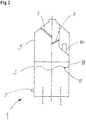
Figure 2 shows a vertical section through a submerged combustion melter; -
Figure 3 is a schematic representation of a burner layout for a melter ofFig. 2 ; and -
Figure 4 schematically shows a production line according to the invention. - With reference to the figures, a toroidal flow pattern is preferably established in which melt follows an ascending direction close to submerged
burners circular burner line 27, flows inwardly towards the center of the circular burner line at the melt surface, and flows downwards in the proximity of the said center. The toroidal flow generates agitation in the melt, ensures good stirring of the melt, and absorption of raw material into the melt. Furthermore, it has been determined that the flow as generated also reduces foam generation at the top of the melt; the gas or foam bubbles being entrained back into the melt, thus reducing its density. - The illustrated
melter 1 comprises: acylindrical melting chamber 3 having an internal diameter of about 2.0 m which contains the melt; anupper chamber 5; and a chimney for evacuation of the fumes. Theupper chamber 5 is equipped withbaffles 7 that prevent any melt projections thrown from thesurface 18 of the melt being entrained into the fumes. Araw material feeder 10 is arranged at theupper chamber 5 and is designed to load fresh raw material into themelter 1 at apoint 11 located above themelt surface 18 and close to the side wall of the melter. Thefeeder 10 comprises a horizontal feeding means, for example a feed screw, which transports the raw material mix to a hopper fastened to the melter, the bottom of which may be opened and closed by a vertical piston. The bottom of the melting chamber comprises six submergedburners circular burner line 27 concentric with the melter axis and having a diameter of about 1.4 m. The melt may be withdrawn from themelting chamber 3 through acontrollable outlet opening 9 located in the melting chamber side wall, close to the melter bottom, substantially opposite thefeeding device 10. The melt withdrawn from the melter may then be allowed to cool and subsequently ground as required. - The temperature within the melt may be between 1400°C and 1600°C, preferably 1450°C and 1550°C, depending on the composition of the melt, desired viscosity and other parameters. Preferably, the melter wall is a double steel wall cooled by a cooling liquid, preferably water. Cooling water connections provided at the external melter wall allow a flow sufficient to withdraw energy from the inside wall such that melt can solidify on the internal wall and the cooling liquid, here water, does not boil. The internal melter wall is not lined with any refractory material.
- The submerged
burners - With reference to
Fig. 4 , raw material from araw material storage 30 is charged into thefurnace 1 as described above, and withdrawn thereof for cooling 32 and further downstream treatments known per se. The discharged melt is allowed to cool at a temperature suitable for further downstream operation, including grinding 34 to appropriate grain size and/or storing 36,38. The grinding is advantageously effected in several stages, including afirst stage 39 that reduces the particle size of the solidified melt to a size suitable for downstream fine grinding 40 which in turn may be carried out in a manner known per se, in several stages, in order to reach a particle size as is common in the cement manufacturing industry. Mostly the final grain size is a powdery grain size. For example, it is such that 100% of the particles pass a 90 µm screen in a dry circuit. The production line further comprises dryers as appropriate and as is known per se; these devices have not been shown in the figures. - With respect to the exemplified melter, it has been found that the turbulent aerated melt showed almost no foam floating at the top of the melt, and it has been determined that the turbulent aerated melt showed a volume (averaged over a 1 minute time period) of 30 - 50% higher than that calculated on the basis of the raw material fed into the melter and maintained at the same temperature. The volume was.
- The high alumina cement obtained is of high quality. The above described production process is less energy demanding then known processes, because of the choice of submerged combustion melters that allow for improved energy transfer to the melt, shorter residence times and thus less heat loss, and because the high stirring leads to a more homogenous melt at reduced melt viscosity, which in turn may allow for operation at reduced temperatures. Furthermore, submerged combustion may advantageously be performed in water-cooled melters which are easier and less costly to maintain and repair and which further allow for recycling of the energy withdrawn from the cooling fluid.
Claims (13)
- Process for the preparation of high alumina cement comprising:- introducing a solid batch material for preparation of high alumina cement into a melter (1), the melter comprising cooled melting chamber walls (19), for example double steel walls separated by circulating cooling liquid, preferably water, and which are not covered by a refractory lining;- melting the solid batch material in the melter (1) by submerged combustion to form a liquid melt, wherein one or more nozzles are arranged in the melter bottom;- withdrawing at least a portion of the liquid melt from the melter (1);- cooling said discharged liquid melt to obtain solidified melt; and- grinding the solidified melt to appropriate grain size.
- Process according to claim 1, wherein heat is recovered from the hot fumes and/or from the cooling liquid.
- Process according to any of claims 1 to 2 wherein heat is recovered from the hot fumes to preheat the raw materials.
- Process according to any of claims 1 to 3 wherein part at least of the melt is withdrawn continuously or batchwise from the melter (1).
- Process according to any of the preceding claims wherein the submerged burners (21,22,23,24,25,26) of the melter (1) are controlled such that the melt volume is increased by at least 8%, preferably at least 10%, more preferably at least 15% or 20%, compared to the volume the melt would have with no burners firing.
- Process according to any of claims 1 to 5 wherein the submerged combustion is performed such that a toroidal melt flow pattern is generated in the melt, having a vertical central axis of revolution, comprising major centrally inwardly convergent flows at the melt surface; the melt moves downwardly at proximity of the vertical central axis of revolution and is recirculated in an ascending movement back to the melt surface, thus defining a toroidal flow pattern.
- Process according to any of claims 1 to 6 wherein the melting step comprises melting the solid batch material, in a submerged combustion melter by subjecting the melt to a flow pattern which when simulated by computational fluid dynamic analysis shows a toroidal melt flow pattern in the melt, comprising major centrally inwardly convergent flow vectors at the melt surface, with the central axis of revolution of the toroid being vertical.
- Process according to claim 7 wherein towards the melter bottom, the flow vectors change orientation showing outward and then upward components.
- Production equipment for the preparation of high alumina cement comprising (i) a submerged combustion melter (1) comprising melting chamber (3) walls (19) and a melting chamber bottom, submerged burners (21,22,23,24,25,26), and equipped with a raw material discharge (10) or feeder and melt outlet (9), (ii) a melt cooling station and (iii) a grinding station; wherein the melting chamber walls (19) are cooled melting chamber walls, for example comprising double steel walls separated by circulating cooling liquid, preferably water, and are not covered by refractory lining.
- Production equipment according to claim 9 wherein submerged combustion burners (21,22,23,24,25,26) are arranged at the melter bottom in a annular burner zone, preferably on a burner circle (27).
- Production equipment according to any of claims 9 or 10 wherein the burners (21,22,23,24,25,26) are arranged with a distance between adjacent burners of 250 - 1250 mm, advantageously 500 - 900 mm, preferably 600 - 800, even more preferably 650 - 750 mm.
- Production equipment according to any of claims 9 to 11 wherein each burner axis and/or a speed vector of the melt moving upwards over or adjacent to the submerged burners (21,22,23,24,25,26) is inclined from the vertical by an angle which is ≥1°, ≥2°, ≥3° or ≥5 and/or which is ≤ 30°, preferably ≤ 15°, more preferably ≤10°, towards the center of the melter.
- Production equipment according to any of claims 9 to 12 wherein each central burner axis is inclined by a swirl angle with respect to a vertical plane passing through a central vertical axis of the melter and the burner center, the swirl angle being ≥1°, ≥2°, ≥3°, ≥5° and/or ≤ 30°, ≤ 20°, ≤ 15° or ≤ 10°.
Priority Applications (3)
| Application Number | Priority Date | Filing Date | Title |
|---|---|---|---|
| SI201630697T SI3250535T1 (en) | 2015-01-27 | 2016-01-27 | Process for the preparation of high alumina cement |
| PL16701664T PL3250535T3 (en) | 2015-01-27 | 2016-01-27 | Process for the preparation of high alumina cement |
| HRP20200319TT HRP20200319T1 (en) | 2015-01-27 | 2020-02-25 | Process for the preparation of high alumina cement |
Applications Claiming Priority (2)
| Application Number | Priority Date | Filing Date | Title |
|---|---|---|---|
| GBGB1501306.3A GB201501306D0 (en) | 2015-01-27 | 2015-01-27 | Process for the preparation of high alumina cement |
| PCT/EP2016/051731 WO2016120347A1 (en) | 2015-01-27 | 2016-01-27 | Process for the preparation of high alumina cement |
Publications (2)
| Publication Number | Publication Date |
|---|---|
| EP3250535A1 EP3250535A1 (en) | 2017-12-06 |
| EP3250535B1 true EP3250535B1 (en) | 2020-01-08 |
Family
ID=52673969
Family Applications (1)
| Application Number | Title | Priority Date | Filing Date |
|---|---|---|---|
| EP16701664.1A Active EP3250535B1 (en) | 2015-01-27 | 2016-01-27 | Process for the preparation of high alumina cement |
Country Status (10)
| Country | Link |
|---|---|
| US (3) | US10604446B2 (en) |
| EP (1) | EP3250535B1 (en) |
| DK (1) | DK3250535T3 (en) |
| ES (1) | ES2773749T3 (en) |
| GB (1) | GB201501306D0 (en) |
| HR (1) | HRP20200319T1 (en) |
| LU (1) | LU93214B1 (en) |
| PL (1) | PL3250535T3 (en) |
| SI (1) | SI3250535T1 (en) |
| WO (1) | WO2016120347A1 (en) |
Cited By (1)
| Publication number | Priority date | Publication date | Assignee | Title |
|---|---|---|---|---|
| WO2021207953A1 (en) * | 2020-04-15 | 2021-10-21 | 天华化工机械及自动化研究设计院有限公司 | Workbench-based low-temperature carbonization furnace oxygen content distribution simulation method |
Families Citing this family (2)
| Publication number | Priority date | Publication date | Assignee | Title |
|---|---|---|---|---|
| GB201501306D0 (en) * | 2015-01-27 | 2015-03-11 | Knauf Insulation And Knauf Insulation Doo Skofja Loka And Knauf Insulation Llc And Knauf Insulation | Process for the preparation of high alumina cement |
| CN113620621B (en) * | 2021-09-02 | 2022-08-09 | 哈尔滨小岭水泥有限责任公司 | Cement manufacturing method |
Family Cites Families (7)
| Publication number | Priority date | Publication date | Assignee | Title |
|---|---|---|---|---|
| US6835244B2 (en) * | 2002-08-26 | 2004-12-28 | Lafarge Canada Inc. | Use of organic carbon-containing minerals |
| JP4602379B2 (en) | 2007-06-05 | 2010-12-22 | 電気化学工業株式会社 | Method for producing alumina cement |
| US20110236846A1 (en) | 2008-01-18 | 2011-09-29 | Gas Technology Institute | Submerged combustion melter |
| CN101811838B (en) * | 2010-04-16 | 2014-09-03 | 四川川恒化工股份有限公司 | Cement production method |
| GB201313654D0 (en) * | 2013-07-31 | 2013-09-11 | Knauf Insulation Doo Skofja Loka | Melting of vitrifiable material |
| GB201313651D0 (en) | 2013-07-31 | 2013-09-11 | Knauf Insulation Doo Skofja Loka | Melting of vitrifiable material |
| GB201501306D0 (en) * | 2015-01-27 | 2015-03-11 | Knauf Insulation And Knauf Insulation Doo Skofja Loka And Knauf Insulation Llc And Knauf Insulation | Process for the preparation of high alumina cement |
-
2015
- 2015-01-27 GB GBGB1501306.3A patent/GB201501306D0/en not_active Ceased
-
2016
- 2016-01-27 LU LU93214A patent/LU93214B1/en active IP Right Grant
- 2016-01-27 WO PCT/EP2016/051731 patent/WO2016120347A1/en active Application Filing
- 2016-01-27 US US15/545,991 patent/US10604446B2/en active Active
- 2016-01-27 SI SI201630697T patent/SI3250535T1/en unknown
- 2016-01-27 PL PL16701664T patent/PL3250535T3/en unknown
- 2016-01-27 ES ES16701664T patent/ES2773749T3/en active Active
- 2016-01-27 EP EP16701664.1A patent/EP3250535B1/en active Active
- 2016-01-27 DK DK16701664.1T patent/DK3250535T3/en active
-
2019
- 2019-08-05 US US16/532,410 patent/US20190359523A1/en not_active Abandoned
- 2019-11-21 US US16/690,505 patent/US11639311B2/en active Active
-
2020
- 2020-02-25 HR HRP20200319TT patent/HRP20200319T1/en unknown
Non-Patent Citations (1)
| Title |
|---|
| None * |
Cited By (1)
| Publication number | Priority date | Publication date | Assignee | Title |
|---|---|---|---|---|
| WO2021207953A1 (en) * | 2020-04-15 | 2021-10-21 | 天华化工机械及自动化研究设计院有限公司 | Workbench-based low-temperature carbonization furnace oxygen content distribution simulation method |
Also Published As
| Publication number | Publication date |
|---|---|
| WO2016120347A1 (en) | 2016-08-04 |
| SI3250535T1 (en) | 2020-04-30 |
| US11639311B2 (en) | 2023-05-02 |
| DK3250535T3 (en) | 2020-03-09 |
| GB201501306D0 (en) | 2015-03-11 |
| US20200087201A1 (en) | 2020-03-19 |
| ES2773749T3 (en) | 2020-07-14 |
| LU93214B1 (en) | 2017-03-30 |
| US20180009710A1 (en) | 2018-01-11 |
| PL3250535T3 (en) | 2020-08-10 |
| US20190359523A1 (en) | 2019-11-28 |
| US10604446B2 (en) | 2020-03-31 |
| HRP20200319T1 (en) | 2020-10-02 |
| EP3250535A1 (en) | 2017-12-06 |
Similar Documents
| Publication | Publication Date | Title |
|---|---|---|
| US11814311B2 (en) | Melter feeding system | |
| US11639311B2 (en) | Process for the preparation of high alumina cement | |
| US20210094862A1 (en) | Process for the preparation of a silica melt | |
| US20230202898A1 (en) | Manufacturing of continuous mineral fibers | |
| EP3027569A1 (en) | Process for manufacturing vitrified material by melting | |
| US20220355351A1 (en) | Glass melting |
Legal Events
| Date | Code | Title | Description |
|---|---|---|---|
| STAA | Information on the status of an ep patent application or granted ep patent |
Free format text: STATUS: THE INTERNATIONAL PUBLICATION HAS BEEN MADE |
|
| PUAI | Public reference made under article 153(3) epc to a published international application that has entered the european phase |
Free format text: ORIGINAL CODE: 0009012 |
|
| STAA | Information on the status of an ep patent application or granted ep patent |
Free format text: STATUS: REQUEST FOR EXAMINATION WAS MADE |
|
| 17P | Request for examination filed |
Effective date: 20170828 |
|
| AK | Designated contracting states |
Kind code of ref document: A1 Designated state(s): AL AT BE BG CH CY CZ DE DK EE ES FI FR GB GR HR HU IE IS IT LI LT LU LV MC MK MT NL NO PL PT RO RS SE SI SK SM TR |
|
| AX | Request for extension of the european patent |
Extension state: BA ME |
|
| DAV | Request for validation of the european patent (deleted) | ||
| DAX | Request for extension of the european patent (deleted) | ||
| STAA | Information on the status of an ep patent application or granted ep patent |
Free format text: STATUS: EXAMINATION IS IN PROGRESS |
|
| 17Q | First examination report despatched |
Effective date: 20180529 |
|
| GRAP | Despatch of communication of intention to grant a patent |
Free format text: ORIGINAL CODE: EPIDOSNIGR1 |
|
| STAA | Information on the status of an ep patent application or granted ep patent |
Free format text: STATUS: GRANT OF PATENT IS INTENDED |
|
| INTG | Intention to grant announced |
Effective date: 20190813 |
|
| GRAS | Grant fee paid |
Free format text: ORIGINAL CODE: EPIDOSNIGR3 |
|
| GRAA | (expected) grant |
Free format text: ORIGINAL CODE: 0009210 |
|
| STAA | Information on the status of an ep patent application or granted ep patent |
Free format text: STATUS: THE PATENT HAS BEEN GRANTED |
|
| AK | Designated contracting states |
Kind code of ref document: B1 Designated state(s): AL AT BE BG CH CY CZ DE DK EE ES FI FR GB GR HR HU IE IS IT LI LT LU LV MC MK MT NL NO PL PT RO RS SE SI SK SM TR |
|
| REG | Reference to a national code |
Ref country code: GB Ref legal event code: FG4D |
|
| REG | Reference to a national code |
Ref country code: CH Ref legal event code: EP |
|
| REG | Reference to a national code |
Ref country code: DE Ref legal event code: R096 Ref document number: 602016027750 Country of ref document: DE |
|
| REG | Reference to a national code |
Ref country code: IE Ref legal event code: FG4D |
|
| REG | Reference to a national code |
Ref country code: AT Ref legal event code: REF Ref document number: 1222504 Country of ref document: AT Kind code of ref document: T Effective date: 20200215 |
|
| REG | Reference to a national code |
Ref country code: CH Ref legal event code: NV Representative=s name: VALIPAT S.A. C/O BOVARD SA NEUCHATEL, CH |
|
| REG | Reference to a national code |
Ref country code: DK Ref legal event code: T3 Effective date: 20200303 |
|
| REG | Reference to a national code |
Ref country code: SE Ref legal event code: TRGR |
|
| REG | Reference to a national code |
Ref country code: NL Ref legal event code: FP |
|
| REG | Reference to a national code |
Ref country code: SK Ref legal event code: T3 Ref document number: E 33680 Country of ref document: SK |
|
| REG | Reference to a national code |
Ref country code: HR Ref legal event code: ODRP Ref document number: P20200319T Country of ref document: HR Payment date: 20200304 Year of fee payment: 5 |
|
| REG | Reference to a national code |
Ref country code: LT Ref legal event code: MG4D |
|
| REG | Reference to a national code |
Ref country code: ES Ref legal event code: FG2A Ref document number: 2773749 Country of ref document: ES Kind code of ref document: T3 Effective date: 20200714 |
|
| PG25 | Lapsed in a contracting state [announced via postgrant information from national office to epo] |
Ref country code: FI Free format text: LAPSE BECAUSE OF FAILURE TO SUBMIT A TRANSLATION OF THE DESCRIPTION OR TO PAY THE FEE WITHIN THE PRESCRIBED TIME-LIMIT Effective date: 20200108 Ref country code: PT Free format text: LAPSE BECAUSE OF FAILURE TO SUBMIT A TRANSLATION OF THE DESCRIPTION OR TO PAY THE FEE WITHIN THE PRESCRIBED TIME-LIMIT Effective date: 20200531 Ref country code: RS Free format text: LAPSE BECAUSE OF FAILURE TO SUBMIT A TRANSLATION OF THE DESCRIPTION OR TO PAY THE FEE WITHIN THE PRESCRIBED TIME-LIMIT Effective date: 20200108 Ref country code: LT Free format text: LAPSE BECAUSE OF FAILURE TO SUBMIT A TRANSLATION OF THE DESCRIPTION OR TO PAY THE FEE WITHIN THE PRESCRIBED TIME-LIMIT Effective date: 20200108 Ref country code: NO Free format text: LAPSE BECAUSE OF FAILURE TO SUBMIT A TRANSLATION OF THE DESCRIPTION OR TO PAY THE FEE WITHIN THE PRESCRIBED TIME-LIMIT Effective date: 20200408 |
|
| PG25 | Lapsed in a contracting state [announced via postgrant information from national office to epo] |
Ref country code: IS Free format text: LAPSE BECAUSE OF FAILURE TO SUBMIT A TRANSLATION OF THE DESCRIPTION OR TO PAY THE FEE WITHIN THE PRESCRIBED TIME-LIMIT Effective date: 20200508 Ref country code: BG Free format text: LAPSE BECAUSE OF FAILURE TO SUBMIT A TRANSLATION OF THE DESCRIPTION OR TO PAY THE FEE WITHIN THE PRESCRIBED TIME-LIMIT Effective date: 20200408 Ref country code: LV Free format text: LAPSE BECAUSE OF FAILURE TO SUBMIT A TRANSLATION OF THE DESCRIPTION OR TO PAY THE FEE WITHIN THE PRESCRIBED TIME-LIMIT Effective date: 20200108 Ref country code: GR Free format text: LAPSE BECAUSE OF FAILURE TO SUBMIT A TRANSLATION OF THE DESCRIPTION OR TO PAY THE FEE WITHIN THE PRESCRIBED TIME-LIMIT Effective date: 20200409 |
|
| REG | Reference to a national code |
Ref country code: HR Ref legal event code: T1PR Ref document number: P20200319 Country of ref document: HR |
|
| REG | Reference to a national code |
Ref country code: DE Ref legal event code: R097 Ref document number: 602016027750 Country of ref document: DE |
|
| PG25 | Lapsed in a contracting state [announced via postgrant information from national office to epo] |
Ref country code: EE Free format text: LAPSE BECAUSE OF FAILURE TO SUBMIT A TRANSLATION OF THE DESCRIPTION OR TO PAY THE FEE WITHIN THE PRESCRIBED TIME-LIMIT Effective date: 20200108 Ref country code: MC Free format text: LAPSE BECAUSE OF FAILURE TO SUBMIT A TRANSLATION OF THE DESCRIPTION OR TO PAY THE FEE WITHIN THE PRESCRIBED TIME-LIMIT Effective date: 20200108 Ref country code: SM Free format text: LAPSE BECAUSE OF FAILURE TO SUBMIT A TRANSLATION OF THE DESCRIPTION OR TO PAY THE FEE WITHIN THE PRESCRIBED TIME-LIMIT Effective date: 20200108 Ref country code: RO Free format text: LAPSE BECAUSE OF FAILURE TO SUBMIT A TRANSLATION OF THE DESCRIPTION OR TO PAY THE FEE WITHIN THE PRESCRIBED TIME-LIMIT Effective date: 20200108 |
|
| PLBE | No opposition filed within time limit |
Free format text: ORIGINAL CODE: 0009261 |
|
| STAA | Information on the status of an ep patent application or granted ep patent |
Free format text: STATUS: NO OPPOSITION FILED WITHIN TIME LIMIT |
|
| REG | Reference to a national code |
Ref country code: AT Ref legal event code: MK05 Ref document number: 1222504 Country of ref document: AT Kind code of ref document: T Effective date: 20200108 |
|
| 26N | No opposition filed |
Effective date: 20201009 |
|
| PG25 | Lapsed in a contracting state [announced via postgrant information from national office to epo] |
Ref country code: IE Free format text: LAPSE BECAUSE OF NON-PAYMENT OF DUE FEES Effective date: 20200127 Ref country code: AT Free format text: LAPSE BECAUSE OF FAILURE TO SUBMIT A TRANSLATION OF THE DESCRIPTION OR TO PAY THE FEE WITHIN THE PRESCRIBED TIME-LIMIT Effective date: 20200108 |
|
| REG | Reference to a national code |
Ref country code: HR Ref legal event code: ODRP Ref document number: P20200319 Country of ref document: HR Payment date: 20210105 Year of fee payment: 6 |
|
| REG | Reference to a national code |
Ref country code: HR Ref legal event code: ODRP Ref document number: P20200319 Country of ref document: HR Payment date: 20220104 Year of fee payment: 7 |
|
| PG25 | Lapsed in a contracting state [announced via postgrant information from national office to epo] |
Ref country code: MT Free format text: LAPSE BECAUSE OF FAILURE TO SUBMIT A TRANSLATION OF THE DESCRIPTION OR TO PAY THE FEE WITHIN THE PRESCRIBED TIME-LIMIT Effective date: 20200108 Ref country code: CY Free format text: LAPSE BECAUSE OF FAILURE TO SUBMIT A TRANSLATION OF THE DESCRIPTION OR TO PAY THE FEE WITHIN THE PRESCRIBED TIME-LIMIT Effective date: 20200108 |
|
| PG25 | Lapsed in a contracting state [announced via postgrant information from national office to epo] |
Ref country code: MK Free format text: LAPSE BECAUSE OF FAILURE TO SUBMIT A TRANSLATION OF THE DESCRIPTION OR TO PAY THE FEE WITHIN THE PRESCRIBED TIME-LIMIT Effective date: 20200108 Ref country code: AL Free format text: LAPSE BECAUSE OF FAILURE TO SUBMIT A TRANSLATION OF THE DESCRIPTION OR TO PAY THE FEE WITHIN THE PRESCRIBED TIME-LIMIT Effective date: 20200108 |
|
| REG | Reference to a national code |
Ref country code: HR Ref legal event code: ODRP Ref document number: P20200319 Country of ref document: HR Payment date: 20230104 Year of fee payment: 8 |
|
| PGFP | Annual fee paid to national office [announced via postgrant information from national office to epo] |
Ref country code: FR Payment date: 20230125 Year of fee payment: 8 Ref country code: DK Payment date: 20230127 Year of fee payment: 8 |
|
| PGFP | Annual fee paid to national office [announced via postgrant information from national office to epo] |
Ref country code: TR Payment date: 20230125 Year of fee payment: 8 Ref country code: SE Payment date: 20230127 Year of fee payment: 8 Ref country code: PL Payment date: 20230103 Year of fee payment: 8 Ref country code: IT Payment date: 20230120 Year of fee payment: 8 Ref country code: HR Payment date: 20230104 Year of fee payment: 8 Ref country code: BE Payment date: 20230127 Year of fee payment: 8 |
|
| P01 | Opt-out of the competence of the unified patent court (upc) registered |
Effective date: 20230421 |
|
| REG | Reference to a national code |
Ref country code: HR Ref legal event code: ODRP Ref document number: P20200319 Country of ref document: HR Payment date: 20240104 Year of fee payment: 9 |
|
| PGFP | Annual fee paid to national office [announced via postgrant information from national office to epo] |
Ref country code: NL Payment date: 20240126 Year of fee payment: 9 |
|
| PGFP | Annual fee paid to national office [announced via postgrant information from national office to epo] |
Ref country code: LU Payment date: 20240129 Year of fee payment: 9 |
|
| PGFP | Annual fee paid to national office [announced via postgrant information from national office to epo] |
Ref country code: ES Payment date: 20240201 Year of fee payment: 9 |
|
| PGFP | Annual fee paid to national office [announced via postgrant information from national office to epo] |
Ref country code: DE Payment date: 20240129 Year of fee payment: 9 Ref country code: CZ Payment date: 20240109 Year of fee payment: 9 Ref country code: GB Payment date: 20240129 Year of fee payment: 9 Ref country code: CH Payment date: 20240202 Year of fee payment: 9 Ref country code: SK Payment date: 20240103 Year of fee payment: 9 |
|
| PGFP | Annual fee paid to national office [announced via postgrant information from national office to epo] |
Ref country code: SI Payment date: 20240104 Year of fee payment: 9 |