EP3250474B1 - Distribution device for a cosmetic product as a spray - Google Patents
Distribution device for a cosmetic product as a spray Download PDFInfo
- Publication number
- EP3250474B1 EP3250474B1 EP16702106.2A EP16702106A EP3250474B1 EP 3250474 B1 EP3250474 B1 EP 3250474B1 EP 16702106 A EP16702106 A EP 16702106A EP 3250474 B1 EP3250474 B1 EP 3250474B1
- Authority
- EP
- European Patent Office
- Prior art keywords
- distribution
- duct
- distribution duct
- distributing
- retaining element
- Prior art date
- Legal status (The legal status is an assumption and is not a legal conclusion. Google has not performed a legal analysis and makes no representation as to the accuracy of the status listed.)
- Not-in-force
Links
Images


Classifications
-
- B—PERFORMING OPERATIONS; TRANSPORTING
- B65—CONVEYING; PACKING; STORING; HANDLING THIN OR FILAMENTARY MATERIAL
- B65D—CONTAINERS FOR STORAGE OR TRANSPORT OF ARTICLES OR MATERIALS, e.g. BAGS, BARRELS, BOTTLES, BOXES, CANS, CARTONS, CRATES, DRUMS, JARS, TANKS, HOPPERS, FORWARDING CONTAINERS; ACCESSORIES, CLOSURES, OR FITTINGS THEREFOR; PACKAGING ELEMENTS; PACKAGES
- B65D49/00—Arrangements or devices for preventing refilling of containers
- B65D49/02—One-way valves
- B65D49/08—Spring-loaded valves
-
- B—PERFORMING OPERATIONS; TRANSPORTING
- B65—CONVEYING; PACKING; STORING; HANDLING THIN OR FILAMENTARY MATERIAL
- B65D—CONTAINERS FOR STORAGE OR TRANSPORT OF ARTICLES OR MATERIALS, e.g. BAGS, BARRELS, BOTTLES, BOXES, CANS, CARTONS, CRATES, DRUMS, JARS, TANKS, HOPPERS, FORWARDING CONTAINERS; ACCESSORIES, CLOSURES, OR FITTINGS THEREFOR; PACKAGING ELEMENTS; PACKAGES
- B65D47/00—Closures with filling and discharging, or with discharging, devices
- B65D47/02—Closures with filling and discharging, or with discharging, devices for initially filling and for preventing subsequent refilling
-
- A—HUMAN NECESSITIES
- A45—HAND OR TRAVELLING ARTICLES
- A45D—HAIRDRESSING OR SHAVING EQUIPMENT; EQUIPMENT FOR COSMETICS OR COSMETIC TREATMENTS, e.g. FOR MANICURING OR PEDICURING
- A45D34/00—Containers or accessories specially adapted for handling liquid toiletry or cosmetic substances, e.g. perfumes
- A45D34/02—Scent flasks, e.g. with evaporator
-
- B—PERFORMING OPERATIONS; TRANSPORTING
- B65—CONVEYING; PACKING; STORING; HANDLING THIN OR FILAMENTARY MATERIAL
- B65B—MACHINES, APPARATUS OR DEVICES FOR, OR METHODS OF, PACKAGING ARTICLES OR MATERIALS; UNPACKING
- B65B31/00—Packaging articles or materials under special atmospheric or gaseous conditions; Adding propellants to aerosol containers
- B65B31/003—Adding propellants in fluid form to aerosol containers
-
- B—PERFORMING OPERATIONS; TRANSPORTING
- B65—CONVEYING; PACKING; STORING; HANDLING THIN OR FILAMENTARY MATERIAL
- B65D—CONTAINERS FOR STORAGE OR TRANSPORT OF ARTICLES OR MATERIALS, e.g. BAGS, BARRELS, BOTTLES, BOXES, CANS, CARTONS, CRATES, DRUMS, JARS, TANKS, HOPPERS, FORWARDING CONTAINERS; ACCESSORIES, CLOSURES, OR FITTINGS THEREFOR; PACKAGING ELEMENTS; PACKAGES
- B65D49/00—Arrangements or devices for preventing refilling of containers
- B65D49/02—One-way valves
- B65D49/04—Weighted valves
-
- B—PERFORMING OPERATIONS; TRANSPORTING
- B65—CONVEYING; PACKING; STORING; HANDLING THIN OR FILAMENTARY MATERIAL
- B65D—CONTAINERS FOR STORAGE OR TRANSPORT OF ARTICLES OR MATERIALS, e.g. BAGS, BARRELS, BOTTLES, BOXES, CANS, CARTONS, CRATES, DRUMS, JARS, TANKS, HOPPERS, FORWARDING CONTAINERS; ACCESSORIES, CLOSURES, OR FITTINGS THEREFOR; PACKAGING ELEMENTS; PACKAGES
- B65D83/00—Containers or packages with special means for dispensing contents
- B65D83/14—Containers for dispensing liquid or semi-liquid contents by internal gaseous pressure, i.e. aerosol containers comprising propellant
- B65D83/44—Valves specially adapted for the discharge of contents; Regulating devices
- B65D83/48—Lift valves, e.g. operated by push action
Definitions
- This invention relates to a device to distribute a product as a spray, of the type comprising a distributing valve comprising:
- the invention also relates to a packaging assembly of a product comprising such a distribution device, and a method of manufacturing this assembly for packaging.
- US 2004/0144803 describes a non-refillable valve device including a housing with an internal cavity including a chamber extending to an end of the housing.
- An elastic sealing member is disposed within the chamber and displaceable between a first position permitting fluid flow into the container and a second position preventing fluid flow into the container.
- FR 2 808 783 describes a distributor comprising a pump with an aspiration system.
- Packaging assemblies comprising devices for distributing of the aforementioned type are known, in particular in FR-A-2 925 032 , and are most often used for the packaging of cosmetic products.
- These cosmetic products are for example perfumes, toilet waters, deodorants or hair styling products. More generally, these cosmetic products are products such as defined in EC Regulation N° 1223/2009 of the European Parliament and the Council of November 30, 2009, relating to cosmetic products.
- the cosmetic product is contained under pressure, generally in liquid form, in a reservoir of the packaging assembly closed by the distribution device.
- the cosmetic product is normally retained in the reservoir by the distribution device.
- the cosmetic product exits spontaneously from the reservoir by the distribution duct under the effect of the pressure present inside the reservoir.
- a diffuser coupled to the exit orifice divides the cosmetic product exiting the reservoir into small droplets which, projected into the air, form a spray.
- these packaging assemblies can again be filled by injecting a new product into the reservoir by the intermediary of the distribution device. To this effect, it is sufficient to displace the actuating rod to the distribution position, then to inject the new product under pressure into the exit orifice.
- An object of the invention is to prevent this fraud by limiting the re-use of empty packaging assemblies.
- the invention has for object a distribution device according to claim 1.
- the distribution device also has one or several of the characteristics of claims 2 to 10 taken in isolation or in any technically possible combination.
- the invention further has for object a packaging assembly according to claim 11.
- the invention also has for object a method for producing a packaging assembly according to claim 12.
- the method for manufacturing also has the feature of claim 13.
- the packaging assembly 10 of Figure 1 comprises a reservoir 12 and a distribution device 14 closing the reservoir 12.
- the reservoir 12 comprises, in a known manner, a wall 20 defining an inner cavity 22 for receiving a cosmetic product. Said inner cavity 22 opens outside of the reservoir 12 by a neck 24 arranged in the wall 20.
- This inner cavity 22 contains a cosmetic product (not shown) such as defined in EC Regulation N° 1223/2009 of the European Parliament and the Council of November 30, 2009, for example a toilet water, a perfume, a deodorant, or a hair styling product.
- a cosmetic product such as defined in EC Regulation N° 1223/2009 of the European Parliament and the Council of November 30, 2009, for example a toilet water, a perfume, a deodorant, or a hair styling product.
- the distribution device 14 is arranged through the neck 24 in such a way as to fully seal the neck 24. It is fixed, at its periphery, to the edge 26 of the neck 24.
- the distribution device 14 comprises a distribution valve 30 and a plate 32.
- the plate 32 defines a passage 34 for the cosmetic product.
- the valve 30 is engaged in this passage 34 and is linked to the plate 32 in such a way as to prevent the passage of a fluid through the passage 34 between the valve 30 and the plate 32 when the pressure of this fluid is less than or equal to the pressure in the cavity 22.
- the plate 32 provides the connection of the valve 30 to the receptacle 12. To this effect, the plate 32 is crimped, at its periphery, to the edge 26.
- the valve 30 comprises a valve body 40, an actuating rod 42, and a return element 44.
- the valve body 40 is arranged entirely on the same side of the plate 32. In particular, the valve body 40 is arranged entirely on the side of the plate 32 oriented towards the cavity 22.
- the valve body 40 is rigidly inked to the plate 32. To this effect, the plate 32 is for example crimped onto the valve body 40.
- the valve body 40 comprises a cylindrical portion 50 that defines an inner chamber 52 that opens outside of the valve body 40 by an opening 54 for the entry of the cosmetic product and an opening 56 for the passage of the rod 42.
- the openings 54, 56 are formed at the axial opposite ends of the cylindrical portion 50. Note that the term "cylindrical” is used here and in the rest of the application in its widest degree of acceptance, and encompasses cylinders of revolution as well as cylinders with a polygonal section.
- the valve body 40 also comprises an appendix 58 for connecting a dip tube (not shown). This appendix 58 protrudes from an axial end of the cylindrical portion 50 and surrounds the opening for the entry 54.
- the valve body 40 further comprises a seal 60 surrounding the exit opening 56. Said seal 60 is arranged bearing against the plate 32 and provides the seal between the valve body 40 and the plate 32.
- the actuating rod 42 is substantially coaxial to the cylindrical portion 50. It extends through the passage 34 and the opening 56. It as such extends in part into the chamber 52 and in part outside of the chamber 52.
- the seal 60 is in contact with a lateral face 61 of said rod 42 in such a way as to carry out a seal between the rod 42 and the valve body 40.
- the actuating rod 42 defines an axial duct 62, inside the rod 52, for the distribution of the cosmetic product.
- This duct 62 opens outside the rod 52 via an orifice 64 for the entry of cosmetic product and by an exit orifice 66 of the cosmetic product.
- the orifice for the entry 64 is arranged in the lateral face 61.
- the exit orifice 66 is arranged in an axial end of the rod 42 located outside the chamber 52.
- the actuating rod 42 is mounted mobile in the chamber 52 along its axis A-A' between a blocking position of the cosmetic product, shown in Figure 1 , wherein the orifice for the entry 64 is not in fluidic communication with the chamber 52, and a distribution position of the cosmetic product (not shown), wherein the orifice for the entry 64 is in fluidic communication with the chamber 52.
- a blocking position of the cosmetic product shown in Figure 1
- a distribution position of the cosmetic product (not shown)
- the orifice for the entry 64 is in fluidic communication with the chamber 52.
- the orifice for the entry 64 in blocking position, the orifice for the entry 64 is positioned facing the seal 60 and, in distribution position, the orifice for entry 64 is positioned in the chamber 52.
- the actuating rod 42 carries an abutment 68 in order to stop the actuating rod 42 when it arrives in blocking position.
- This abutment 68 is also adapted to prevent the actuating rod 42 from entirely exiting the chamber 52.
- said abutment 68 is, in the example shown, adapted to be in contact with the seal 60 when the rod 42 is in blocking position.
- the abutment 68 is as such, in the example shown, constituted by a shoulder, oriented towards the seal 60, of the rod 42.
- the return element 44 is adapted to urge the rod 42 towards its blocking position. Said blocking position as such constitutes a rest position of the rod 42.
- the return element 44 is in particular arranged in the chamber 52.
- this return element 44 is a compression spring interposed between the axial end of the rod 42 positioned in the chamber 52 and the axial end of the cylindrical portion 50 wherein is arranged the opening for the entry 54.
- the distribution device 14 also comprises a non-return valve 70 arranged inside the actuating rod 42 in order to prevent the circulation of a fluid in the duct 62 from the exit orifice 66 towards the orifice for the entry 64.
- This non-return valve 70 comprises a member 72 mounted mobile in the duct 62 between a seat 74 for receiving the mobile member 72 and an element 76 for retaining the mobile member 72.
- This member 72 is in particular mounted mobile in translation along the axis A-A' between a closed position, wherein it is received in the seat 74, and an open position, wherein it is bearing against the retaining element 76.
- the mobile member 72 is inserted between the seat 74 and the retaining element 76. It has a mass less than one-tenth of the product of the pressure inside the cavity 22 by the radial section of the mobile member 72. It is, in the example shown, constituted by a ball.
- the seat 74 and the retaining element 76 are successively arranged in the duct 62, the retaining element 76 being inserted, along the duct 62, between the seat 74 and the exit orifice 66. They are adapted to contain the mobile member 72 in the portion of the duct 62 between the seat 74 and the retaining element 76.
- the seat 74 is adapted to receive the mobile member 72 in the closed position and so that, in this position, the duct 62 is entirely sealed.
- the retaining element 76 is adapted so that the mobile member 72 comes to bear against it when it is in its open position and so that, in this position, the duct 62 is partially free.
- the seat 74 is formed by a narrowing of the duct 62.
- This narrowing comprises a tapered portion of the duct 62, substantially coaxial to the rod 42, with the tip of the cone being oriented opposite the exit orifice 66, the orifice for entry 64 opening into said tapered portion, between the tip of the cone and a plane wherein the diameter of the cone is substantially equal to the diameter of the mobile member 72.
- the retaining element 76 comprises, in reference to Figure 2 , a plurality of appendices 78 each protruding from the wall 80 of the duct 62, from a base (not referenced) to a free end 82.
- Each free end 82 is at a distance from the central axis of the duct 62 less than the radius of the mobile member 72.
- the free ends 82 of the appendices 78 are at a distance from one another, in such a way that axial channels 84 are arranged between the appendices 78.
- These axial channels 84 allow for the circulation of a fluid from one end to the other of the duct 62 even when the mobile member 72 is in its open position bearing against the retaining element 76.
- the appendices 78 are preferably of a single piece with the wall 80.
- the packaging assembly according to the second embodiment is distinguished from the first embodiment only by the shape of the retaining element 76.
- the retaining element 76 is formed by a clasp extending through the duct 62, substantially perpendicularly to the axis of the duct 62.
- the packaging assembly according to the third embodiment is distinguished from the first embodiment only by the shape of the retaining element 76.
- the retaining element 76 is formed by an added insert force fitted into the duct 62 and maintained in the duct 62 by the forces of friction between this insert and the wall 80 of the duct 62.
- This insert comprises four panels 86 (only three of them can be seen in Figure 4 ) oriented at ninety degrees from one another and all joining together along a line substantially coaxial to the duct 62, in such a way that the insert has a radial section in the shape of a cross.
- Each panel 86 comprises a junction edge 90 with the other panels 86, an edge 92 bearing against the wall 80 of the duct 62, opposite the junction edge 90, a free edge 94, contained in a radial plane and oriented towards the exit orifice 66, and an edge 96 for receiving the mobile member 72, contained in a radial plane and oriented towards the seat 74.
- Each panel 86 also comprises a cut-away 98 connecting the edge for receiving 96 to the bearing edge 92.
- the packaging assembly according to the fourth embodiment is distinguished from the first embodiment only by the shape of the seat 74.
- the seat 74 is also formed by a narrowing of the duct 62.
- This narrowing comprises a tapered portion of the duct 62, substantially coaxial to the rod 42, flaring in the direction of the exit orifice 66.
- This narrowing is interposed between two substantially cylindrical portions 100, 102 of the duct 62, a first portion 100 wherein opens the orifice for entry 64 and a second portion 102 wherein is positioned the retaining element 76.
- the narrowing is here formed by a local tightening of the actuating rod 42.
- the wall 80 of the duct 62 has a substantially constant thickness all along the duct 62, and to the narrowing of the duct 62 corresponds an annular recess 104 of a complementary shape formed in the lateral face 61 of the rod 42.
- the packaging assembly according to the fifth embodiment is distinguished from the first embodiment by the shape of the seat 74 and of the retaining element 76.
- the seat 74 is also formed by a narrowing of the duct 62.
- this narrowing is not formed by a tapered portion of the duct 62, but by an abrupt variation in the diameter of the duct 62.
- the duct 62 as such comprises a portion of large diameter 106, wherein is arranged the retaining element 76, and a portion of small diameter 108, into which opens the orifice for entry 64.
- the portion of large diameter 106 has a diameter greater than the diameter of the mobile member 72.
- the portion of small diameter 108 has a diameter less than the diameter of the mobile member 72.
- Each portion 106, 108 is, in the example shown, substantially cylindrical.
- the wall 80 of the duct 62 defines a shoulder 110 oriented towards the exit orifice 66.
- This shoulder 110 is in particular contained in a radial plane.
- Axial ribs 112 extend along the wall 80 of the duct 62 in the portion of large diameter 106. Each rib 112 protrudes from said wall 80 towards the central axis of the duct 62, and extends from one axial end of the duct 62 to the opposite axial end. Said ribs 112 are spaced from one another and are preferably distributed regularly at the periphery of the duct 62.
- each rib 112 is at a distance from the central axis of the duct 62 greater than the radius of the mobile member 72 and preferably substantially equal to said radius of the mobile member 72. As such the guiding of the mobile member 72 in the duct 62 is improved.
- the retaining element 76 is formed by a plurality of appendices 114 each protruding from the wall 80 of the duct 62 towards the central axis of the duct 62.
- Said appendices 114 are spaced from one another and are preferably distributed regularly at the periphery of the duct 62. Each appendix 114 is in particular, as shown, aligned axially with a rib 112.
- Each appendix 114 comprises a base (not referenced), wherein it is connected to the wall 80, and a free end 115 opposite said base. Each free end 115 is at a distance from the central axis of the duct 62 less than the radius of the mobile member 72.
- Each appendix 114 has, in the example shown, a shape of a half-disc. The base of the appendix 114 is then formed by the diameter of said half-disc.
- Each appendix 114 is preferably overmolded on the wall 80 of the duct 62 inside the duct 62. Alternatively, each appendix 114 is integral with the wall 80.
- the packaging assembly according to the sixth embodiment is distinguished from the first embodiment by the shape of the seat 74 and of the retaining element 76.
- the seat 74 is also formed by a narrowing of the duct 62.
- this narrowing is not formed by a tapered portion of the duct 62, but by an abrupt variation in the diameter of the duct 62.
- the duct 62 as such comprises a portion of large diameter 116, wherein is arranged the retaining element 76, and a portion of small diameter 118, into which opens the orifice for entry 64.
- the portion of large diameter 116 has a diameter greater than the diameter of the mobile member 72.
- the portion of small diameter 118 has a diameter less than the diameter of the mobile member 72.
- Each portion 116, 118 is, in the example shown, a general cylindrical shape.
- the wall 80 of the duct 62 defines a shoulder 120 oriented towards the exit orifice 66.
- This shoulder 120 is in particular contained in a radial plane.
- the retaining element 76 is also formed by a narrowing of the duct 62, in particular by a narrowing of the portion of large diameter 116.
- this narrowing is formed by a local tightening of the actuating rod 42.
- to the narrowing of the duct 62 forming the retaining element 76 corresponds at least one recess 122 formed in the lateral face 61 of the rod 42.
- the or each recess 122 opens, via a first end, into the lateral face 61 of the rod 42 by an opening 124, and is closed at its opposite end by a bottom 126.
- the or each recess 122 is isolated from the duct 62 by its bottom 126.
- the or each recess 122 is advantageously, as shown, at a distance from the central axis of the duct 62 less than the average radius of the duct 62.
- the bottom 126 of the or of each recess 122 is advantageously at a distance from the central axis of the duct 62 less than the average radius of the duct 62.
- each recesses 122 there are two recesses 122, with each one having substantially a shape of a cylinder with axis orthogonal to the axis of the duct 62.
- the reservoir 12 and the distribution device 14 are supplied.
- the distribution device 14 is complete, except for the mobile member 72, which is not yet installed in the duct 62.
- the reservoir 12 and the distribution device 14 are then assembled to one another, in such a way that the distribution device 14 closes the reservoir 12.
- the plate 32 is crimped to the edge 26 surrounding the mouth 24 through which the cavity 22 opens to the outside of the reservoir 20.
- the reservoir 12 is then filled with the cosmetic product.
- the actuating rod 42 is displaced in a distribution position, then the cosmetic product is injected, under pressure, into the orifice for exiting 66.
- the cosmetic product flows without hindrance into the duct 62 to the orifice for entry 64; the orifice for entry 64 being in the chamber 52, the cosmetic product is as such released in the chamber 52; it then follows the opening for entry 54 and, from there, is in the cavity 22.
- the actuating rod 42 is brought back to the locking position. Then the mobile member 72 is inserted by force into the duct 62, in such a way as to pass the retaining element 76.
- the method for manufacturing the packaging assembly according to the fourth embodiment is identical to the method for manufacturing described hereinabove.
- the methods for manufacturing the packaging assemblies according to the second, third, fifth and sixth embodiments are distinguished from the method for manufacturing described hereinabove only in that, when the distribution device 14 is assembled to the reservoir 12, the distribution device 14 does not yet comprise the retaining element 76.
- the retaining element 76 is formed only after the insertion of the mobile member 72 into the duct 62. The inserting of the mobile member 72 into the duct 62 then does not have to be carried out by force.
- the distribution device 14 comprises the mobile member 72 and the retaining element 76 when it is assembled to the reservoir 12.
- the filling of the reservoir 12 is then no longer carried out by injecting the cosmetic product into the orifice for exiting 66, but by injecting the cosmetic product into the passage 34, between the actuating rod 42 and the edge of the passage 34.
- the pressure must be sufficiently high as to allow the cosmetic product to flow between the seal 60 and the plate 62. This alternative applies to all of the embodiments described hereinabove.
- a user actuates the packaging assembly 10 in such a way as to provoke the displacement of the rod 42 to its distribution position.
- the cosmetic product under the effect of the pressure in the reservoir 12, penetrates into the duct 62 by the orifice for entry 64.
- This product which is at the pressure of the reservoir 12, exerts a force on the mobile member 72 that is greater than its weight, and as such provokes the displacement of the latter into open position.
- the cosmetic product can then flow into the duct 62 to the exit orifice 66 by going around the mobile member 72.
- the cosmetic product can as such be distributed normally.
- non-return valve 70 used is very discreet, in such a way that the objective hereinabove is achieved without increasing the encumbrance of the packaging assembly.
- the invention extends to the distribution devices that comprise a retaining element 76 of any one of the embodiments described hereinabove and a seat 74 of another of these embodiments.
Landscapes
- Engineering & Computer Science (AREA)
- Mechanical Engineering (AREA)
- Chemical & Material Sciences (AREA)
- Dispersion Chemistry (AREA)
- Containers And Packaging Bodies Having A Special Means To Remove Contents (AREA)
- Nozzles (AREA)
Description
- This invention relates to a device to distribute a product as a spray, of the type comprising a distributing valve comprising:
- a valve body, defining an inner chamber of the valve body that opens onto the outside of the valve body by an opening for the entry of the product,
- an actuating rod, inserted into an exit opening of the valve body, the rod defining an interior distribution duct, said distribution duct opening onto the outside of the rod via an orifice for the entry of the product and via an exit orifice of the product, the actuating rod being mounted mobile in the chamber of the valve body between a distribution position of the cosmetic product, wherein the orifice for the entry is in fluidic communication with the chamber and the exit orifice is arranged outside of the chamber, and a blocking position of the cosmetic product, wherein the orifice for the entry is not in fluidic communication with the chamber, and
- a return element of the actuating rod to its blocking position.
- The invention also relates to a packaging assembly of a product comprising such a distribution device, and a method of manufacturing this assembly for packaging.
-
US 2004/0144803 describes a non-refillable valve device including a housing with an internal cavity including a chamber extending to an end of the housing. An elastic sealing member is disposed within the chamber and displaceable between a first position permitting fluid flow into the container and a second position preventing fluid flow into the container. -
FR 2 808 783 - Packaging assemblies comprising devices for distributing of the aforementioned type are known, in particular in
FR-A-2 925 032 - The cosmetic product is contained under pressure, generally in liquid form, in a reservoir of the packaging assembly closed by the distribution device. The cosmetic product is normally retained in the reservoir by the distribution device. However, when the actuating rod is displaced to the distribution position, the cosmetic product exits spontaneously from the reservoir by the distribution duct under the effect of the pressure present inside the reservoir. Most often, a diffuser coupled to the exit orifice divides the cosmetic product exiting the reservoir into small droplets which, projected into the air, form a spray.
- Once empty, these packaging assemblies can again be filled by injecting a new product into the reservoir by the intermediary of the distribution device. To this effect, it is sufficient to displace the actuating rod to the distribution position, then to inject the new product under pressure into the exit orifice.
- However, unscrupulous people take advantage of this possibility of reusing empty packaging assemblies to fill the used brand packaging assemblies with products of lesser quality, then to sell these articles by presenting them as originals. This fraud, other than the lack of revenue that it creates for the brands concerned and the damage that it brings to the image of these brands, induces a high sanitary risk for the purchasers of fraudulent products.
- An object of the invention is to prevent this fraud by limiting the re-use of empty packaging assemblies.
- To this effect, the invention has for object a distribution device according to claim 1.
- According to particular embodiments of the invention, the distribution device also has one or several of the characteristics of claims 2 to 10 taken in isolation or in any technically possible combination.
- The invention further has for object a packaging assembly according to claim 11.
- The invention also has for object a method for producing a packaging assembly according to claim 12.
- According to one particular embodiment of the invention, the method for manufacturing also has the feature of claim 13.
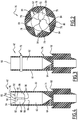
- Further features and advantages of the invention will emerge after reading the following description given solely as an example with reference to the appended drawings in which:
-
Figure 1 is a cross-section view of a portion of a packaging assembly according to a first embodiment of the invention, -
Figure 2 is a cross-section view along plane II-II of the packaging assembly onFigure 1 , -
Figure 3 is a cross-section view of an actuating rod of a packaging assembly according to a second embodiment of the invention, -
Figure 4 is a partial cross-section view of an actuating rod of a packaging assembly according to a third embodiment of the invention, -
Figure 5 is a cross-section view of an actuating rod of a packaging assembly according to a fourth embodiment of the invention, -
Figure 6 is a cross-section view of an actuating rod of a packaging assembly according to a fifth embodiment of the invention, and -
Figure 7 is a cross-section view of an actuating rod of a packaging assembly according to a sixth embodiment of the invention. - The
packaging assembly 10 ofFigure 1 comprises a reservoir 12 and adistribution device 14 closing the reservoir 12. - The reservoir 12 comprises, in a known manner, a
wall 20 defining aninner cavity 22 for receiving a cosmetic product. Saidinner cavity 22 opens outside of the reservoir 12 by aneck 24 arranged in thewall 20. - This
inner cavity 22 contains a cosmetic product (not shown) such as defined in EC Regulation N° 1223/2009 of the European Parliament and the Council of November 30, 2009, for example a toilet water, a perfume, a deodorant, or a hair styling product. - The
distribution device 14 is arranged through theneck 24 in such a way as to fully seal theneck 24. It is fixed, at its periphery, to theedge 26 of theneck 24. - The
distribution device 14 comprises adistribution valve 30 and aplate 32. - The
plate 32 defines apassage 34 for the cosmetic product. Thevalve 30 is engaged in thispassage 34 and is linked to theplate 32 in such a way as to prevent the passage of a fluid through thepassage 34 between thevalve 30 and theplate 32 when the pressure of this fluid is less than or equal to the pressure in thecavity 22. - The
plate 32 provides the connection of thevalve 30 to the receptacle 12. To this effect, theplate 32 is crimped, at its periphery, to theedge 26. - The
valve 30 comprises avalve body 40, anactuating rod 42, and areturn element 44. - The
valve body 40 is arranged entirely on the same side of theplate 32. In particular, thevalve body 40 is arranged entirely on the side of theplate 32 oriented towards thecavity 22. - The
valve body 40 is rigidly inked to theplate 32. To this effect, theplate 32 is for example crimped onto thevalve body 40. - The
valve body 40 comprises acylindrical portion 50 that defines aninner chamber 52 that opens outside of thevalve body 40 by anopening 54 for the entry of the cosmetic product and anopening 56 for the passage of therod 42. Theopenings cylindrical portion 50. Note that the term "cylindrical" is used here and in the rest of the application in its widest degree of acceptance, and encompasses cylinders of revolution as well as cylinders with a polygonal section. - The
valve body 40 also comprises anappendix 58 for connecting a dip tube (not shown). Thisappendix 58 protrudes from an axial end of thecylindrical portion 50 and surrounds the opening for theentry 54. - The
valve body 40 further comprises aseal 60 surrounding theexit opening 56. Saidseal 60 is arranged bearing against theplate 32 and provides the seal between thevalve body 40 and theplate 32. - The actuating
rod 42 is substantially coaxial to thecylindrical portion 50. It extends through thepassage 34 and the opening 56. It as such extends in part into thechamber 52 and in part outside of thechamber 52. Theseal 60 is in contact with alateral face 61 of saidrod 42 in such a way as to carry out a seal between therod 42 and thevalve body 40. - The
actuating rod 42 defines anaxial duct 62, inside therod 52, for the distribution of the cosmetic product. Thisduct 62 opens outside therod 52 via anorifice 64 for the entry of cosmetic product and by anexit orifice 66 of the cosmetic product. The orifice for theentry 64 is arranged in thelateral face 61. Theexit orifice 66 is arranged in an axial end of therod 42 located outside thechamber 52. - The actuating
rod 42 is mounted mobile in thechamber 52 along its axis A-A' between a blocking position of the cosmetic product, shown inFigure 1 , wherein the orifice for theentry 64 is not in fluidic communication with thechamber 52, and a distribution position of the cosmetic product (not shown), wherein the orifice for theentry 64 is in fluidic communication with thechamber 52. In particular, in blocking position, the orifice for theentry 64 is positioned facing theseal 60 and, in distribution position, the orifice forentry 64 is positioned in thechamber 52. - The actuating
rod 42 carries anabutment 68 in order to stop the actuatingrod 42 when it arrives in blocking position. Thisabutment 68 is also adapted to prevent theactuating rod 42 from entirely exiting thechamber 52. To this effect, saidabutment 68 is, in the example shown, adapted to be in contact with theseal 60 when therod 42 is in blocking position. Theabutment 68 is as such, in the example shown, constituted by a shoulder, oriented towards theseal 60, of therod 42. - The
return element 44 is adapted to urge therod 42 towards its blocking position. Said blocking position as such constitutes a rest position of therod 42. - The
return element 44 is in particular arranged in thechamber 52. In the example shown, thisreturn element 44 is a compression spring interposed between the axial end of therod 42 positioned in thechamber 52 and the axial end of thecylindrical portion 50 wherein is arranged the opening for theentry 54. - According to the invention, the
distribution device 14 also comprises anon-return valve 70 arranged inside the actuatingrod 42 in order to prevent the circulation of a fluid in theduct 62 from theexit orifice 66 towards the orifice for theentry 64. - This
non-return valve 70 comprises amember 72 mounted mobile in theduct 62 between aseat 74 for receiving themobile member 72 and anelement 76 for retaining themobile member 72. Thismember 72 is in particular mounted mobile in translation along the axis A-A' between a closed position, wherein it is received in theseat 74, and an open position, wherein it is bearing against the retainingelement 76. - The
mobile member 72 is inserted between theseat 74 and the retainingelement 76. It has a mass less than one-tenth of the product of the pressure inside thecavity 22 by the radial section of themobile member 72. It is, in the example shown, constituted by a ball. - The
seat 74 and the retainingelement 76 are successively arranged in theduct 62, the retainingelement 76 being inserted, along theduct 62, between theseat 74 and theexit orifice 66. They are adapted to contain themobile member 72 in the portion of theduct 62 between theseat 74 and the retainingelement 76. - The
seat 74 is adapted to receive themobile member 72 in the closed position and so that, in this position, theduct 62 is entirely sealed. - The retaining
element 76 is adapted so that themobile member 72 comes to bear against it when it is in its open position and so that, in this position, theduct 62 is partially free. - In the first embodiment, the
seat 74 is formed by a narrowing of theduct 62. This narrowing comprises a tapered portion of theduct 62, substantially coaxial to therod 42, with the tip of the cone being oriented opposite theexit orifice 66, the orifice forentry 64 opening into said tapered portion, between the tip of the cone and a plane wherein the diameter of the cone is substantially equal to the diameter of themobile member 72. - Still in the first embodiment, the retaining
element 76 comprises, in reference toFigure 2 , a plurality ofappendices 78 each protruding from thewall 80 of theduct 62, from a base (not referenced) to afree end 82. Eachfree end 82 is at a distance from the central axis of theduct 62 less than the radius of themobile member 72. The free ends 82 of theappendices 78 are at a distance from one another, in such a way thataxial channels 84 are arranged between theappendices 78. Theseaxial channels 84 allow for the circulation of a fluid from one end to the other of theduct 62 even when themobile member 72 is in its open position bearing against the retainingelement 76. - The
appendices 78 are preferably of a single piece with thewall 80. - In reference to
Figure 3 , the packaging assembly according to the second embodiment is distinguished from the first embodiment only by the shape of the retainingelement 76. In this embodiment, the retainingelement 76 is formed by a clasp extending through theduct 62, substantially perpendicularly to the axis of theduct 62. - In reference to
Figure 4 , the packaging assembly according to the third embodiment is distinguished from the first embodiment only by the shape of the retainingelement 76. In this embodiment, the retainingelement 76 is formed by an added insert force fitted into theduct 62 and maintained in theduct 62 by the forces of friction between this insert and thewall 80 of theduct 62. - This insert comprises four panels 86 (only three of them can be seen in
Figure 4 ) oriented at ninety degrees from one another and all joining together along a line substantially coaxial to theduct 62, in such a way that the insert has a radial section in the shape of a cross. Eachpanel 86 comprises ajunction edge 90 with theother panels 86, anedge 92 bearing against thewall 80 of theduct 62, opposite thejunction edge 90, afree edge 94, contained in a radial plane and oriented towards theexit orifice 66, and anedge 96 for receiving themobile member 72, contained in a radial plane and oriented towards theseat 74. Eachpanel 86 also comprises a cut-away 98 connecting the edge for receiving 96 to the bearingedge 92. - In reference to
Figure 5 , the packaging assembly according to the fourth embodiment is distinguished from the first embodiment only by the shape of theseat 74. In this embodiment, theseat 74 is also formed by a narrowing of theduct 62. This narrowing comprises a tapered portion of theduct 62, substantially coaxial to therod 42, flaring in the direction of theexit orifice 66. This narrowing is interposed between two substantiallycylindrical portions duct 62, afirst portion 100 wherein opens the orifice forentry 64 and asecond portion 102 wherein is positioned the retainingelement 76. - The narrowing is here formed by a local tightening of the actuating
rod 42. In other terms, thewall 80 of theduct 62 has a substantially constant thickness all along theduct 62, and to the narrowing of theduct 62 corresponds anannular recess 104 of a complementary shape formed in thelateral face 61 of therod 42. - In reference to
Figure 6 , the packaging assembly according to the fifth embodiment is distinguished from the first embodiment by the shape of theseat 74 and of the retainingelement 76. - In this embodiment, the
seat 74 is also formed by a narrowing of theduct 62. However, unlike the first embodiment, this narrowing is not formed by a tapered portion of theduct 62, but by an abrupt variation in the diameter of theduct 62. Theduct 62 as such comprises a portion oflarge diameter 106, wherein is arranged the retainingelement 76, and a portion ofsmall diameter 108, into which opens the orifice forentry 64. - The portion of
large diameter 106 has a diameter greater than the diameter of themobile member 72. The portion ofsmall diameter 108 has a diameter less than the diameter of themobile member 72. - Each
portion - At the interface between said
portions wall 80 of theduct 62 defines ashoulder 110 oriented towards theexit orifice 66. Thisshoulder 110 is in particular contained in a radial plane. -
Axial ribs 112 extend along thewall 80 of theduct 62 in the portion oflarge diameter 106. Eachrib 112 protrudes from saidwall 80 towards the central axis of theduct 62, and extends from one axial end of theduct 62 to the opposite axial end. Saidribs 112 are spaced from one another and are preferably distributed regularly at the periphery of theduct 62. - The free end of each
rib 112 is at a distance from the central axis of theduct 62 greater than the radius of themobile member 72 and preferably substantially equal to said radius of themobile member 72. As such the guiding of themobile member 72 in theduct 62 is improved. - The retaining
element 76 is formed by a plurality ofappendices 114 each protruding from thewall 80 of theduct 62 towards the central axis of theduct 62. - Said
appendices 114 are spaced from one another and are preferably distributed regularly at the periphery of theduct 62. Eachappendix 114 is in particular, as shown, aligned axially with arib 112. - Each
appendix 114 comprises a base (not referenced), wherein it is connected to thewall 80, and a free end 115 opposite said base. Each free end 115 is at a distance from the central axis of theduct 62 less than the radius of themobile member 72. - Each
appendix 114 has, in the example shown, a shape of a half-disc. The base of theappendix 114 is then formed by the diameter of said half-disc. - Each
appendix 114 is preferably overmolded on thewall 80 of theduct 62 inside theduct 62. Alternatively, eachappendix 114 is integral with thewall 80. - In reference to
Figure 7 , the packaging assembly according to the sixth embodiment is distinguished from the first embodiment by the shape of theseat 74 and of the retainingelement 76. - In this embodiment, the
seat 74 is also formed by a narrowing of theduct 62. However, unlike the first embodiment, this narrowing is not formed by a tapered portion of theduct 62, but by an abrupt variation in the diameter of theduct 62. Theduct 62 as such comprises a portion oflarge diameter 116, wherein is arranged the retainingelement 76, and a portion ofsmall diameter 118, into which opens the orifice forentry 64. - The portion of
large diameter 116 has a diameter greater than the diameter of themobile member 72. The portion ofsmall diameter 118 has a diameter less than the diameter of themobile member 72. - Each
portion - At the interface between said
portions wall 80 of theduct 62 defines ashoulder 120 oriented towards theexit orifice 66. Thisshoulder 120 is in particular contained in a radial plane. - The retaining
element 76 is also formed by a narrowing of theduct 62, in particular by a narrowing of the portion oflarge diameter 116. - In this sixth embodiment, this narrowing is formed by a local tightening of the actuating
rod 42. In other terms, to the narrowing of theduct 62 forming the retainingelement 76 corresponds at least onerecess 122 formed in thelateral face 61 of therod 42. - The or each
recess 122 opens, via a first end, into thelateral face 61 of therod 42 by anopening 124, and is closed at its opposite end by a bottom 126. The or eachrecess 122 is isolated from theduct 62 by itsbottom 126. - The or each
recess 122 is advantageously, as shown, at a distance from the central axis of theduct 62 less than the average radius of theduct 62. In other terms, thebottom 126 of the or of eachrecess 122 is advantageously at a distance from the central axis of theduct 62 less than the average radius of theduct 62. As such, any attempt to remove the retainingelement 76, for example by cutting, would result in generating the piercing of therod 42. - In the example shown, there are two
recesses 122, with each one having substantially a shape of a cylinder with axis orthogonal to the axis of theduct 62. - In reference to
Figure 1 , a method for manufacturing apackaging assembly 10 according to the first embodiment shall now be described. - Firstly, the reservoir 12 and the
distribution device 14 are supplied. At this stage, thedistribution device 14 is complete, except for themobile member 72, which is not yet installed in theduct 62. - The reservoir 12 and the
distribution device 14 are then assembled to one another, in such a way that thedistribution device 14 closes the reservoir 12. To this effect, theplate 32 is crimped to theedge 26 surrounding themouth 24 through which thecavity 22 opens to the outside of thereservoir 20. - The reservoir 12 is then filled with the cosmetic product. To this effect, the actuating
rod 42 is displaced in a distribution position, then the cosmetic product is injected, under pressure, into the orifice for exiting 66. In the absence of themobile member 72, the cosmetic product flows without hindrance into theduct 62 to the orifice forentry 64; the orifice forentry 64 being in thechamber 52, the cosmetic product is as such released in thechamber 52; it then follows the opening forentry 54 and, from there, is in thecavity 22. - Once the reservoir 12 is filled, the actuating
rod 42 is brought back to the locking position. Then themobile member 72 is inserted by force into theduct 62, in such a way as to pass the retainingelement 76. - The method for manufacturing the packaging assembly according to the fourth embodiment is identical to the method for manufacturing described hereinabove.
- The methods for manufacturing the packaging assemblies according to the second, third, fifth and sixth embodiments are distinguished from the method for manufacturing described hereinabove only in that, when the
distribution device 14 is assembled to the reservoir 12, thedistribution device 14 does not yet comprise the retainingelement 76. In these methods for manufacturing, the retainingelement 76 is formed only after the insertion of themobile member 72 into theduct 62. The inserting of themobile member 72 into theduct 62 then does not have to be carried out by force. - Alternatively, the
distribution device 14 comprises themobile member 72 and the retainingelement 76 when it is assembled to the reservoir 12. The filling of the reservoir 12 is then no longer carried out by injecting the cosmetic product into the orifice for exiting 66, but by injecting the cosmetic product into thepassage 34, between the actuatingrod 42 and the edge of thepassage 34. Note that, in this case, the pressure must be sufficiently high as to allow the cosmetic product to flow between theseal 60 and theplate 62. This alternative applies to all of the embodiments described hereinabove. - The use of an assembly for packaging according to any of the preceding embodiments shall now be described, in reference to
Figure 1 . - With normal use, a user actuates the
packaging assembly 10 in such a way as to provoke the displacement of therod 42 to its distribution position. When therod 42 is in distribution position, the cosmetic product, under the effect of the pressure in the reservoir 12, penetrates into theduct 62 by the orifice forentry 64. This product, which is at the pressure of the reservoir 12, exerts a force on themobile member 72 that is greater than its weight, and as such provokes the displacement of the latter into open position. The cosmetic product can then flow into theduct 62 to theexit orifice 66 by going around themobile member 72. The cosmetic product can as such be distributed normally. - In the case of a fraudulent attempt to fill the reservoir 12, a user injects a product under pressure into the
duct 62 via theexit orifice 66. This product bears against themobile member 72 and thrusts it in closed position against theseat 74. In this position, themobile member 72 fully seals theduct 62, in such a way that the product injected cannot penetrate into the reservoir 12: the filling of the reservoir 12 is as such prevented - Thanks to the invention described hereinabove, the re-use of empty assemblies for packaging is limited, as the filling of the reservoir 12 via the
rod 42 is rendered impossible. - Furthermore, the
non-return valve 70 used is very discreet, in such a way that the objective hereinabove is achieved without increasing the encumbrance of the packaging assembly. - Note that, although the characteristics of the invention have been described in separate embodiments, characteristics presented in different embodiments can be combined with one another without leaving the scope of the invention. In particular, the invention extends to the distribution devices that comprise a retaining
element 76 of any one of the embodiments described hereinabove and aseat 74 of another of these embodiments.
Claims (13)
- Device for distributing (14) a product as a spray, comprising a distributing valve (30) comprising:- a valve body (40), defining an inner chamber (52) of the valve body (40) that opens onto the outside of the valve body (40) by an opening for the entry (54) of the product,- an actuating rod (42), inserted into an exit opening (56) of the valve body (40), the rod defining an interior distribution duct (62), said distribution duct (62) opening onto the outside of the rod (42) via an orifice (64) for the entry of the product and via an exit orifice (66) of the product, the actuating rod (42) being mounted mobile in the chamber (52) of the valve body (40) between a distribution position of the cosmetic product, wherein the orifice for the entry (64) is in fluidic communication with the chamber (52) and the exit orifice (66) is arranged outside of the chamber (52), and a blocking position of the cosmetic product, wherein the orifice for the entry (64) is not in fluidic communication with the chamber (52), and- a return element (44) of the actuating rod (42) to its blocking position, the distribution device (14) comprising a non-return valve (70),characterised by the non-return valve (70) being arranged inside the actuating rod (42) in order to prevent the circulation of a fluid in the distribution duct (62) from the exit orifice (66) towards the orifice for the entry (64), said non-return valve (70) comprising a member (72) mounted mobile in the distribution duct (62).
- Device for distributing (14) according to claim 1, wherein the non-return valve (70) further comprises a seat (74) for receiving the mobile member (72) and an element (76) for retaining the mobile member (72) arranged successively in the distribution duct (62), the retaining member (76) being interposed, along the distribution duct (62), between the seat (74) and the exit orifice (66), the mobile member (72) being mounted mobile in the distribution duct (62) between said seat (74) and said retaining element (76), between a closed position wherein the mobile member (72) is received in the seat (74), the distribution duct (62) being fully sealed, and an open position wherein the mobile member (72) is bearing against the retaining element (76), the distribution duct (62) being partially free.
- Device for distributing (14) according to claim 2, wherein the retaining element (76) is an element added onto the actuating rod (42).
- Device for distributing (14) according to claim 2, wherein the retaining element (76) is molded inside the distribution duct (62).
- Device for distributing (14) according to claim 2, wherein the retaining element (76) is formed by a narrowing of the distribution duct (62).
- Device for distributing (14) according to any of claims 2 to 5, wherein the seat (74) is formed by a narrowing of the distribution duct (62).
- Device for distributing (14) according to claim 5 or 6, wherein the narrowing of the distribution duct (62) is formed by a local tightening of the actuating rod (42).
- Device for distributing (14) according to claims 5 and 7 taken together, wherein the rod (42) has, in line with the retaining element (76), at least one recess (122) formed in its lateral face (61), the recess (122) being at a distance from the central axis of the distribution duct (62) less than an average radius of the distribution duct (62).
- Device for distributing (14) according to any of claims 2 to 8, wherein the retaining element (76) defines at least one axial channel (84) for the circulation of the product when the mobile member (72) is in open position.
- Device for distributing (14) according to any of the preceding claims wherein the mobile member (72) is a ball.
- Packaging assembly (10) of a cosmetic product, comprising a reservoir (12) containing a cosmetic product and a distribution device (14) closing said reservoir (12), wherein the distribution device (14) is a distribution device such according to any of the preceding claims.
- Method for manufacturing a packaging assembly according to claim 11, comprising the following successive steps:- supplying of the reservoir (12) and of the distribution valve (30),- closing of the reservoir (12) with the distribution valve (30),- filling of the reservoir (12) by displacement of the actuating rod (42) in distribution position and injection of the cosmetic product under pressure in the exit orifice (66), and- inserting of the mobile member (72) into the distribution duct (62).
- Method of manufacture according to claim 12, comprising a step of forming a retaining element (76), said step following the step of inserting.
Applications Claiming Priority (2)
| Application Number | Priority Date | Filing Date | Title |
|---|---|---|---|
| FR1550676A FR3032095B1 (en) | 2015-01-29 | 2015-01-29 | DEVICE FOR DISPENSING A COSMETIC PRODUCT IN AEROSOL FORM |
| PCT/EP2016/051918 WO2016120447A1 (en) | 2015-01-29 | 2016-01-29 | Distribution device to distribute a cosmetic product as a spray |
Publications (2)
| Publication Number | Publication Date |
|---|---|
| EP3250474A1 EP3250474A1 (en) | 2017-12-06 |
| EP3250474B1 true EP3250474B1 (en) | 2018-11-28 |
Family
ID=52824465
Family Applications (1)
| Application Number | Title | Priority Date | Filing Date |
|---|---|---|---|
| EP16702106.2A Not-in-force EP3250474B1 (en) | 2015-01-29 | 2016-01-29 | Distribution device for a cosmetic product as a spray |
Country Status (5)
| Country | Link |
|---|---|
| US (1) | US20180002080A1 (en) |
| EP (1) | EP3250474B1 (en) |
| JP (1) | JP2018510818A (en) |
| FR (1) | FR3032095B1 (en) |
| WO (1) | WO2016120447A1 (en) |
Families Citing this family (5)
| Publication number | Priority date | Publication date | Assignee | Title |
|---|---|---|---|---|
| WO2015083642A1 (en) * | 2013-12-03 | 2015-06-11 | 株式会社三谷バルブ | Aerosol housing mechanism and aerosol product provided with said aerosol housing mechanism |
| BR102017015802A2 (en) * | 2016-07-25 | 2018-02-14 | Precision Valve Corporation | VALVE ASSEMBLY, AND ASSEMBLY METHOD OF A NON-RECHARGEABLE VALVE |
| FR3140076B1 (en) * | 2022-09-22 | 2025-12-05 | Oreal | Rapid gassing valve for refillable aerosol |
| FR3167637A1 (en) * | 2024-10-17 | 2026-04-24 | Chanel Parfums Beaute | Device for filling a bottle with a telescopic cannula |
| WO2026082731A1 (en) * | 2024-10-17 | 2026-04-23 | Chanel Parfums Beaute | Device for filling a vial comprising a telescopic cannula |
Family Cites Families (13)
| Publication number | Priority date | Publication date | Assignee | Title |
|---|---|---|---|---|
| US3666148A (en) * | 1969-10-13 | 1972-05-30 | Gillette Co | Aerosol valve with safety relief device |
| CH650469A5 (en) * | 1982-11-10 | 1985-07-31 | Werding Winfried J | DEVICE FOR CONTROLLING THE THRUST OF A FLUID USING TURBULENCE. |
| EP0598640B1 (en) * | 1992-11-17 | 1996-09-11 | Liquid Air Corporation | Refill-preventing valve for non-refillable containers |
| AU4106897A (en) * | 1997-04-01 | 1998-10-22 | Soudal | Coupling |
| FR2808783A1 (en) * | 2000-05-11 | 2001-11-16 | Lir France Sa | Cosmetic dispenser comprises body and head with pump and valve and supply pipe submerged in product and dispensing pipe emerging through orifice to outside |
| US6932238B2 (en) * | 2003-01-28 | 2005-08-23 | Air Liquide Advanced Technologies U.S. Llc | Non-refillable valve device |
| JP2004330128A (en) * | 2003-05-09 | 2004-11-25 | Mitani Valve Co Ltd | Stem valve for flowing pressure discharge |
| JP2005087824A (en) * | 2003-09-16 | 2005-04-07 | Mitani Valve Co Ltd | Jet device and jet unit |
| US20090014679A1 (en) * | 2007-07-13 | 2009-01-15 | Precision Valve Corporation | Plastic aerosol valve and method of assembly, mounting and retention |
| FR2925032B1 (en) | 2007-12-17 | 2012-09-21 | Oreal | VALVE FOR CONTAINER UNDER PRESSURE OF PRODUCT STORAGE AND DISTRIBUTION AND CONTAINER PROVIDED WITH SUCH A VALVE |
| EP2919746B1 (en) * | 2013-06-28 | 2019-05-29 | The Procter and Gamble Company | Aerosol hairspray product comprising a spraying device |
| US9915357B1 (en) * | 2015-02-19 | 2018-03-13 | TSI Products, Inc. | Actuator with back pressure valve |
| BR102017015802A2 (en) * | 2016-07-25 | 2018-02-14 | Precision Valve Corporation | VALVE ASSEMBLY, AND ASSEMBLY METHOD OF A NON-RECHARGEABLE VALVE |
-
2015
- 2015-01-29 FR FR1550676A patent/FR3032095B1/en not_active Expired - Fee Related
-
2016
- 2016-01-29 US US15/546,840 patent/US20180002080A1/en not_active Abandoned
- 2016-01-29 WO PCT/EP2016/051918 patent/WO2016120447A1/en not_active Ceased
- 2016-01-29 JP JP2017540120A patent/JP2018510818A/en not_active Ceased
- 2016-01-29 EP EP16702106.2A patent/EP3250474B1/en not_active Not-in-force
Non-Patent Citations (1)
| Title |
|---|
| None * |
Also Published As
| Publication number | Publication date |
|---|---|
| FR3032095A1 (en) | 2016-08-05 |
| FR3032095B1 (en) | 2017-03-03 |
| JP2018510818A (en) | 2018-04-19 |
| WO2016120447A1 (en) | 2016-08-04 |
| US20180002080A1 (en) | 2018-01-04 |
| EP3250474A1 (en) | 2017-12-06 |
Similar Documents
| Publication | Publication Date | Title |
|---|---|---|
| US20180002080A1 (en) | Distribution device to distribute a cosmetic product as a spray | |
| EP2181053B1 (en) | A valve for an aerosol device | |
| US9381530B2 (en) | Dispensing device for fluid substances | |
| US4407481A (en) | Valve assembly for a pressurized aerosol-dispensing container | |
| US9409761B2 (en) | Refillable bottle for dispensing a fluid product | |
| US10099844B2 (en) | Device for dispensing a cosmetic product in aerosol form, associated assembly and method | |
| AU2011287709B2 (en) | Metering valve for pressurized vial | |
| US20180022537A1 (en) | Non-refilling aerosol valve | |
| CN104718140B (en) | Aerosol distributes proportional valve | |
| US6986444B2 (en) | Dispenser for discharging a fluid medium | |
| CN100445182C (en) | Fluid product dispensing valve and fluid product dispensing device having such a valve | |
| CN103492086B (en) | Fluid product dispensing pump and fluid product dispensing device including the pump | |
| US10035641B2 (en) | Pouch reservoirs for casings used to dispense pressurized products and casings comprising same | |
| CN101316660A (en) | Dispensing pump for fluid formulations | |
| US9233384B2 (en) | Discharging device | |
| US8579531B2 (en) | Device for dispensing a cosmetic product and associated storage method | |
| EP1539616B1 (en) | Plug style pump | |
| US5375635A (en) | Tamper evident head for pressurized tanks including a lockout device | |
| WO2024061503A1 (en) | Rapid gassing valve for refillable aerosol | |
| CN104736455B (en) | Aerosol distributes proportional valve | |
| US20220395075A1 (en) | Device for dispensing a liquid or pasty product | |
| KR101040968B1 (en) | Metering container with pouch and valve assembly thereof | |
| KR20110046250A (en) | Cartridge with integrated sealing cap | |
| JP2002320884A (en) | Valve device and aerosol jet device |
Legal Events
| Date | Code | Title | Description |
|---|---|---|---|
| STAA | Information on the status of an ep patent application or granted ep patent |
Free format text: STATUS: THE INTERNATIONAL PUBLICATION HAS BEEN MADE |
|
| PUAI | Public reference made under article 153(3) epc to a published international application that has entered the european phase |
Free format text: ORIGINAL CODE: 0009012 |
|
| STAA | Information on the status of an ep patent application or granted ep patent |
Free format text: STATUS: REQUEST FOR EXAMINATION WAS MADE |
|
| 17P | Request for examination filed |
Effective date: 20170728 |
|
| AK | Designated contracting states |
Kind code of ref document: A1 Designated state(s): AL AT BE BG CH CY CZ DE DK EE ES FI FR GB GR HR HU IE IS IT LI LT LU LV MC MK MT NL NO PL PT RO RS SE SI SK SM TR |
|
| AX | Request for extension of the european patent |
Extension state: BA ME |
|
| DAV | Request for validation of the european patent (deleted) | ||
| DAX | Request for extension of the european patent (deleted) | ||
| GRAP | Despatch of communication of intention to grant a patent |
Free format text: ORIGINAL CODE: EPIDOSNIGR1 |
|
| STAA | Information on the status of an ep patent application or granted ep patent |
Free format text: STATUS: GRANT OF PATENT IS INTENDED |
|
| RIC1 | Information provided on ipc code assigned before grant |
Ipc: B65D 49/04 20060101ALI20180508BHEP Ipc: B65D 47/02 20060101ALI20180508BHEP Ipc: B65B 31/00 20060101ALI20180508BHEP Ipc: B65D 83/48 20060101AFI20180508BHEP |
|
| INTG | Intention to grant announced |
Effective date: 20180613 |
|
| RIN1 | Information on inventor provided before grant (corrected) |
Inventor name: COCAUD, OLIVIER Inventor name: LAVABLE, NADINE Inventor name: ALBISETTI, NICOLAS Inventor name: CROIBIER, SEBASTIEN Inventor name: CANNAROZZO, FRANK Inventor name: DOVERGNE, OLIVIER Inventor name: JOLLET, FREDERIC Inventor name: MAGNE, CAROLE Inventor name: LORENTE GONZALEZ, SONIA Inventor name: DOERFLINGER, SYLVIE Inventor name: PINHEIRO-BAIRRAS, BERNARDINO |
|
| GRAS | Grant fee paid |
Free format text: ORIGINAL CODE: EPIDOSNIGR3 |
|
| GRAA | (expected) grant |
Free format text: ORIGINAL CODE: 0009210 |
|
| STAA | Information on the status of an ep patent application or granted ep patent |
Free format text: STATUS: THE PATENT HAS BEEN GRANTED |
|
| AK | Designated contracting states |
Kind code of ref document: B1 Designated state(s): AL AT BE BG CH CY CZ DE DK EE ES FI FR GB GR HR HU IE IS IT LI LT LU LV MC MK MT NL NO PL PT RO RS SE SI SK SM TR |
|
| REG | Reference to a national code |
Ref country code: CH Ref legal event code: EP |
|
| REG | Reference to a national code |
Ref country code: AT Ref legal event code: REF Ref document number: 1069975 Country of ref document: AT Kind code of ref document: T Effective date: 20181215 |
|
| REG | Reference to a national code |
Ref country code: DE Ref legal event code: R096 Ref document number: 602016007604 Country of ref document: DE |
|
| REG | Reference to a national code |
Ref country code: IE Ref legal event code: FG4D |
|
| REG | Reference to a national code |
Ref country code: NL Ref legal event code: MP Effective date: 20181128 |
|
| REG | Reference to a national code |
Ref country code: LT Ref legal event code: MG4D |
|
| REG | Reference to a national code |
Ref country code: AT Ref legal event code: MK05 Ref document number: 1069975 Country of ref document: AT Kind code of ref document: T Effective date: 20181128 |
|
| PG25 | Lapsed in a contracting state [announced via postgrant information from national office to epo] |
Ref country code: ES Free format text: LAPSE BECAUSE OF FAILURE TO SUBMIT A TRANSLATION OF THE DESCRIPTION OR TO PAY THE FEE WITHIN THE PRESCRIBED TIME-LIMIT Effective date: 20181128 Ref country code: LV Free format text: LAPSE BECAUSE OF FAILURE TO SUBMIT A TRANSLATION OF THE DESCRIPTION OR TO PAY THE FEE WITHIN THE PRESCRIBED TIME-LIMIT Effective date: 20181128 Ref country code: LT Free format text: LAPSE BECAUSE OF FAILURE TO SUBMIT A TRANSLATION OF THE DESCRIPTION OR TO PAY THE FEE WITHIN THE PRESCRIBED TIME-LIMIT Effective date: 20181128 Ref country code: HR Free format text: LAPSE BECAUSE OF FAILURE TO SUBMIT A TRANSLATION OF THE DESCRIPTION OR TO PAY THE FEE WITHIN THE PRESCRIBED TIME-LIMIT Effective date: 20181128 Ref country code: NO Free format text: LAPSE BECAUSE OF FAILURE TO SUBMIT A TRANSLATION OF THE DESCRIPTION OR TO PAY THE FEE WITHIN THE PRESCRIBED TIME-LIMIT Effective date: 20190228 Ref country code: BG Free format text: LAPSE BECAUSE OF FAILURE TO SUBMIT A TRANSLATION OF THE DESCRIPTION OR TO PAY THE FEE WITHIN THE PRESCRIBED TIME-LIMIT Effective date: 20190228 Ref country code: FI Free format text: LAPSE BECAUSE OF FAILURE TO SUBMIT A TRANSLATION OF THE DESCRIPTION OR TO PAY THE FEE WITHIN THE PRESCRIBED TIME-LIMIT Effective date: 20181128 Ref country code: IS Free format text: LAPSE BECAUSE OF FAILURE TO SUBMIT A TRANSLATION OF THE DESCRIPTION OR TO PAY THE FEE WITHIN THE PRESCRIBED TIME-LIMIT Effective date: 20190328 Ref country code: AT Free format text: LAPSE BECAUSE OF FAILURE TO SUBMIT A TRANSLATION OF THE DESCRIPTION OR TO PAY THE FEE WITHIN THE PRESCRIBED TIME-LIMIT Effective date: 20181128 |
|
| PG25 | Lapsed in a contracting state [announced via postgrant information from national office to epo] |
Ref country code: SE Free format text: LAPSE BECAUSE OF FAILURE TO SUBMIT A TRANSLATION OF THE DESCRIPTION OR TO PAY THE FEE WITHIN THE PRESCRIBED TIME-LIMIT Effective date: 20181128 Ref country code: AL Free format text: LAPSE BECAUSE OF FAILURE TO SUBMIT A TRANSLATION OF THE DESCRIPTION OR TO PAY THE FEE WITHIN THE PRESCRIBED TIME-LIMIT Effective date: 20181128 Ref country code: RS Free format text: LAPSE BECAUSE OF FAILURE TO SUBMIT A TRANSLATION OF THE DESCRIPTION OR TO PAY THE FEE WITHIN THE PRESCRIBED TIME-LIMIT Effective date: 20181128 Ref country code: PT Free format text: LAPSE BECAUSE OF FAILURE TO SUBMIT A TRANSLATION OF THE DESCRIPTION OR TO PAY THE FEE WITHIN THE PRESCRIBED TIME-LIMIT Effective date: 20190328 Ref country code: GR Free format text: LAPSE BECAUSE OF FAILURE TO SUBMIT A TRANSLATION OF THE DESCRIPTION OR TO PAY THE FEE WITHIN THE PRESCRIBED TIME-LIMIT Effective date: 20190301 |
|
| PG25 | Lapsed in a contracting state [announced via postgrant information from national office to epo] |
Ref country code: NL Free format text: LAPSE BECAUSE OF FAILURE TO SUBMIT A TRANSLATION OF THE DESCRIPTION OR TO PAY THE FEE WITHIN THE PRESCRIBED TIME-LIMIT Effective date: 20181128 |
|
| PG25 | Lapsed in a contracting state [announced via postgrant information from national office to epo] |
Ref country code: CZ Free format text: LAPSE BECAUSE OF FAILURE TO SUBMIT A TRANSLATION OF THE DESCRIPTION OR TO PAY THE FEE WITHIN THE PRESCRIBED TIME-LIMIT Effective date: 20181128 Ref country code: IT Free format text: LAPSE BECAUSE OF FAILURE TO SUBMIT A TRANSLATION OF THE DESCRIPTION OR TO PAY THE FEE WITHIN THE PRESCRIBED TIME-LIMIT Effective date: 20181128 Ref country code: PL Free format text: LAPSE BECAUSE OF FAILURE TO SUBMIT A TRANSLATION OF THE DESCRIPTION OR TO PAY THE FEE WITHIN THE PRESCRIBED TIME-LIMIT Effective date: 20181128 Ref country code: DK Free format text: LAPSE BECAUSE OF FAILURE TO SUBMIT A TRANSLATION OF THE DESCRIPTION OR TO PAY THE FEE WITHIN THE PRESCRIBED TIME-LIMIT Effective date: 20181128 |
|
| REG | Reference to a national code |
Ref country code: DE Ref legal event code: R119 Ref document number: 602016007604 Country of ref document: DE |
|
| PG25 | Lapsed in a contracting state [announced via postgrant information from national office to epo] |
Ref country code: SM Free format text: LAPSE BECAUSE OF FAILURE TO SUBMIT A TRANSLATION OF THE DESCRIPTION OR TO PAY THE FEE WITHIN THE PRESCRIBED TIME-LIMIT Effective date: 20181128 Ref country code: SK Free format text: LAPSE BECAUSE OF FAILURE TO SUBMIT A TRANSLATION OF THE DESCRIPTION OR TO PAY THE FEE WITHIN THE PRESCRIBED TIME-LIMIT Effective date: 20181128 Ref country code: MC Free format text: LAPSE BECAUSE OF FAILURE TO SUBMIT A TRANSLATION OF THE DESCRIPTION OR TO PAY THE FEE WITHIN THE PRESCRIBED TIME-LIMIT Effective date: 20181128 Ref country code: RO Free format text: LAPSE BECAUSE OF FAILURE TO SUBMIT A TRANSLATION OF THE DESCRIPTION OR TO PAY THE FEE WITHIN THE PRESCRIBED TIME-LIMIT Effective date: 20181128 Ref country code: EE Free format text: LAPSE BECAUSE OF FAILURE TO SUBMIT A TRANSLATION OF THE DESCRIPTION OR TO PAY THE FEE WITHIN THE PRESCRIBED TIME-LIMIT Effective date: 20181128 |
|
| REG | Reference to a national code |
Ref country code: CH Ref legal event code: PL |
|
| PG25 | Lapsed in a contracting state [announced via postgrant information from national office to epo] |
Ref country code: LU Free format text: LAPSE BECAUSE OF NON-PAYMENT OF DUE FEES Effective date: 20190129 |
|
| PLBE | No opposition filed within time limit |
Free format text: ORIGINAL CODE: 0009261 |
|
| STAA | Information on the status of an ep patent application or granted ep patent |
Free format text: STATUS: NO OPPOSITION FILED WITHIN TIME LIMIT |
|
| REG | Reference to a national code |
Ref country code: BE Ref legal event code: MM Effective date: 20190131 |
|
| REG | Reference to a national code |
Ref country code: IE Ref legal event code: MM4A |
|
| PG25 | Lapsed in a contracting state [announced via postgrant information from national office to epo] |
Ref country code: FR Free format text: LAPSE BECAUSE OF NON-PAYMENT OF DUE FEES Effective date: 20190131 Ref country code: SI Free format text: LAPSE BECAUSE OF FAILURE TO SUBMIT A TRANSLATION OF THE DESCRIPTION OR TO PAY THE FEE WITHIN THE PRESCRIBED TIME-LIMIT Effective date: 20181128 Ref country code: DE Free format text: LAPSE BECAUSE OF NON-PAYMENT OF DUE FEES Effective date: 20190801 |
|
| 26N | No opposition filed |
Effective date: 20190829 |
|
| PG25 | Lapsed in a contracting state [announced via postgrant information from national office to epo] |
Ref country code: BE Free format text: LAPSE BECAUSE OF NON-PAYMENT OF DUE FEES Effective date: 20190131 |
|
| PG25 | Lapsed in a contracting state [announced via postgrant information from national office to epo] |
Ref country code: CH Free format text: LAPSE BECAUSE OF NON-PAYMENT OF DUE FEES Effective date: 20190131 Ref country code: LI Free format text: LAPSE BECAUSE OF NON-PAYMENT OF DUE FEES Effective date: 20190131 |
|
| PG25 | Lapsed in a contracting state [announced via postgrant information from national office to epo] |
Ref country code: IE Free format text: LAPSE BECAUSE OF NON-PAYMENT OF DUE FEES Effective date: 20190129 |
|
| PG25 | Lapsed in a contracting state [announced via postgrant information from national office to epo] |
Ref country code: TR Free format text: LAPSE BECAUSE OF FAILURE TO SUBMIT A TRANSLATION OF THE DESCRIPTION OR TO PAY THE FEE WITHIN THE PRESCRIBED TIME-LIMIT Effective date: 20181128 |
|
| PG25 | Lapsed in a contracting state [announced via postgrant information from national office to epo] |
Ref country code: MT Free format text: LAPSE BECAUSE OF NON-PAYMENT OF DUE FEES Effective date: 20190129 |
|
| GBPC | Gb: european patent ceased through non-payment of renewal fee |
Effective date: 20200129 |
|
| PG25 | Lapsed in a contracting state [announced via postgrant information from national office to epo] |
Ref country code: GB Free format text: LAPSE BECAUSE OF NON-PAYMENT OF DUE FEES Effective date: 20200129 |
|
| PG25 | Lapsed in a contracting state [announced via postgrant information from national office to epo] |
Ref country code: CY Free format text: LAPSE BECAUSE OF FAILURE TO SUBMIT A TRANSLATION OF THE DESCRIPTION OR TO PAY THE FEE WITHIN THE PRESCRIBED TIME-LIMIT Effective date: 20181128 |
|
| PG25 | Lapsed in a contracting state [announced via postgrant information from national office to epo] |
Ref country code: HU Free format text: LAPSE BECAUSE OF FAILURE TO SUBMIT A TRANSLATION OF THE DESCRIPTION OR TO PAY THE FEE WITHIN THE PRESCRIBED TIME-LIMIT; INVALID AB INITIO Effective date: 20160129 |
|
| PG25 | Lapsed in a contracting state [announced via postgrant information from national office to epo] |
Ref country code: MK Free format text: LAPSE BECAUSE OF FAILURE TO SUBMIT A TRANSLATION OF THE DESCRIPTION OR TO PAY THE FEE WITHIN THE PRESCRIBED TIME-LIMIT Effective date: 20181128 |