EP3249978A1 - Closed-loop clock calibration method, terminal and computer storage medium - Google Patents
Closed-loop clock calibration method, terminal and computer storage medium Download PDFInfo
- Publication number
- EP3249978A1 EP3249978A1 EP15878526.1A EP15878526A EP3249978A1 EP 3249978 A1 EP3249978 A1 EP 3249978A1 EP 15878526 A EP15878526 A EP 15878526A EP 3249978 A1 EP3249978 A1 EP 3249978A1
- Authority
- EP
- European Patent Office
- Prior art keywords
- calibration
- period
- factor
- clock
- calibration factor
- Prior art date
- Legal status (The legal status is an assumption and is not a legal conclusion. Google has not performed a legal analysis and makes no representation as to the accuracy of the status listed.)
- Granted
Links
Images


Classifications
-
- H—ELECTRICITY
- H04—ELECTRIC COMMUNICATION TECHNIQUE
- H04W—WIRELESS COMMUNICATION NETWORKS
- H04W52/00—Power management, e.g. Transmission Power Control [TPC] or power classes
- H04W52/02—Power saving arrangements
- H04W52/0209—Power saving arrangements in terminal devices
- H04W52/0261—Power saving arrangements in terminal devices managing power supply demand, e.g. depending on battery level
- H04W52/0287—Power saving arrangements in terminal devices managing power supply demand, e.g. depending on battery level changing the clock frequency of a controller in the equipment
-
- H—ELECTRICITY
- H04—ELECTRIC COMMUNICATION TECHNIQUE
- H04W—WIRELESS COMMUNICATION NETWORKS
- H04W52/00—Power management, e.g. Transmission Power Control [TPC] or power classes
- H04W52/02—Power saving arrangements
- H04W52/0209—Power saving arrangements in terminal devices
- H04W52/0261—Power saving arrangements in terminal devices managing power supply demand, e.g. depending on battery level
- H04W52/0287—Power saving arrangements in terminal devices managing power supply demand, e.g. depending on battery level changing the clock frequency of a controller in the equipment
- H04W52/029—Power saving arrangements in terminal devices managing power supply demand, e.g. depending on battery level changing the clock frequency of a controller in the equipment reducing the clock frequency of the controller
-
- Y—GENERAL TAGGING OF NEW TECHNOLOGICAL DEVELOPMENTS; GENERAL TAGGING OF CROSS-SECTIONAL TECHNOLOGIES SPANNING OVER SEVERAL SECTIONS OF THE IPC; TECHNICAL SUBJECTS COVERED BY FORMER USPC CROSS-REFERENCE ART COLLECTIONS [XRACs] AND DIGESTS
- Y02—TECHNOLOGIES OR APPLICATIONS FOR MITIGATION OR ADAPTATION AGAINST CLIMATE CHANGE
- Y02D—CLIMATE CHANGE MITIGATION TECHNOLOGIES IN INFORMATION AND COMMUNICATION TECHNOLOGIES [ICT], I.E. INFORMATION AND COMMUNICATION TECHNOLOGIES AIMING AT THE REDUCTION OF THEIR OWN ENERGY USE
- Y02D30/00—Reducing energy consumption in communication networks
- Y02D30/70—Reducing energy consumption in communication networks in wireless communication networks
Definitions
- the disclosure relates to a clock calibration technology in the field of wireless communication, and particularly to a closed-loop clock calibration method, a terminal and a computer storage medium.
- the terminal when a terminal in the system executes no service or fewer services, the terminal may usually enter a Discontinuous Reception (DRX) time period.
- DRX time period is divided into two time periods: an active time period and a sleep time period, as shown in Fig. 1 .
- the terminal may turn off most of internal operation units when entering the sleep time period.
- the operation unit includes a system clock which may also be called as a high-frequency clock.
- the terminal turns off the high-frequency clock and adopts a low-frequency clock with a lower frequency and lower power consumption to maintain system timing.
- most of terminals in the wireless cellular communication system usually maintain system timing by adopting low-frequency clocks with a frequency of 32.768kHz.
- the terminal When entering the active time period, the terminal recovers the system timing through the low-frequency clock in the sleep time period at first, and converts the low-frequency clock into a high-frequency clock through multiplying the low-frequency clock by a calibration factor, so as to recover the system timing. Since the low-frequency clock has relatively lower accuracy and stability and cannot perform temperature compensation, the low-frequency clock may be influenced by a factor such as an environment and a temperature. After the terminal recovers the system timing, the system timing may have a calibration deviation, and the terminal further performs frequency and time synchronization, and then may initiate or receive paging. It can be seen that the terminal should regulate the calibration factor to make the recovered system timing more accurate, thereby improving execution efficiency of a subsequent synchronization operation.
- a system clock (high-frequency clock) is usually adopted as a calibration clock, to calibrate a low-frequency clock. That is, the high-frequency clock and the low-frequency clock operate simultaneously and count respectively, and after a time period, a ratio of the high-frequency clock to the low-frequency clock is calculated to obtain a calibration factor.
- the high-frequency clock may be influenced by clock jitter. Therefore, the existing calibration factor regulation manner should increase a calibration time to ensure calibration accuracy. The higher the calibration accuracy is, the longer the calibration time is. Usually, the calibration time should be more than 100ms. However, an excessively long calibration time may reduce a sleep time of a terminal in the sleep time period, which may increase standby power consumption of the terminal.
- An embodiment of the disclosure provides a closed-loop clock calibration method.
- the method includes the following steps.
- n th calibration period clock calibration is performed according to a calibration factor of an nth calibration period, and a calibration error of the n th calibration period is obtained.
- a calibration factor of an ( n + 1 ) th calibration period is obtained according to the calibration error and calibration factor of the n th calibration period, where n is a positive integer.
- the method may further include a step in which a calibration factor of a first calibration period is preset.
- the step of presetting the calibration factor of the first calibration period may include the following steps.
- a calibration factor is obtained according to a theoretical frequency value of a system clock and a theoretical frequency value of a low-frequency clock.
- the obtained calibration factor is preset as the calibration factor of the first calibration period.
- the step of presetting the calibration factor of the first calibration period may include the following steps.
- the system clock and the low-frequency clock are caused to operate simultaneously and count respectively.
- a ratio of a count value of a system clock period to a count value of a low-frequency clock period is calculated to obtain a calibration factor.
- the obtained calibration factor is preset as the calibration factor of the first calibration period.
- the step of, in the n th calibration period, performing clock calibration according to the calibration factor of the n th calibration period and obtaining the calibration error of the nth calibration period may include the following steps.
- the low-frequency clock is converted into converted into the system clock to recover system timing through multiplying low-frequency clock by the calibration factor of the n th calibration period.
- the step of obtaining the calibration factor of the ( n + 1 ) th calibration period according to the calibration error and calibration factor of the n th calibration period may include the following steps.
- the calibration period may be preset to be at least one DRX time period.
- an embodiment of the disclosure further provides a terminal.
- the terminal includes: a calibration error extraction unit and a calibration factor regulation unit.
- the calibration error extraction unit is arranged to: in an n th calibration period, perform clock calibration according to a calibration factor of the n th calibration period, and obtain a calibration error of the n th calibration period.
- the calibration factor regulation unit is arranged to obtain a calibration factor of an ( n + 1 ) th calibration period according to the calibration error and calibration factor of the n th calibration period, where n is a positive integer.
- the terminal may further include an initial value presetting unit.
- the initial value presetting unit is arranged to preset a calibration factor of a first calibration period.
- the initial value presetting unit may be further arranged to obtain a calibration factor according to a theoretical frequency value of a system clock and a theoretical frequency value of a low-frequency clock, and preset the obtained calibration factor as the calibration factor of the first calibration period.
- the initial value presetting unit may be further arranged to: in a preset time period, cause the system clock and the low-frequency clock to operate simultaneously and count respectively; after the preset time period, calculate a ratio of a count value of a system clock period to a count value of a low-frequency clock period to obtain a calibration factor; and preset the obtained calibration factor as the calibration factor of the first calibration period.
- the calibration period may be preset to be at least one DRX time period.
- An embodiment of the disclosure further provides a computer storage medium including a set of instructions.
- the instructions when being executed, causes at least one processor to execute the abovementioned closed-loop clock calibration method.
- the clock calibration is performed according to the calibration factor of the n th calibration period, and the calibration error of the n th calibration period is obtained.
- the calibration factor of the ( n + 1 ) th calibration period is obtained according to the calibration error and calibration factor of the n th calibration period, where n is a positive integer. In this manner, closed-loop clock calibration is performed according to the calibration error, which may not only improve clock calibration accuracy but also reduce standby power consumption of the terminal.
- clock calibration is performed according to a calibration factor of an n th calibration period, and a calibration error of the n th calibration period is obtained; and a calibration factor of an ( n + 1 ) th calibration period is obtained according to the calibration error and calibration factor of the nth calibration period, where n is a positive integer.
- a closed-loop clock calibration flow provided by an embodiment of the disclosure includes the following steps.
- Step S201 in an n th calibration period, clock calibration is performed according to a calibration factor of the n th calibration period, and a calibration error of the nth calibration period is obtained, where n is a positive integer.
- DRX Discontinuous Reception
- a calibration factor used in a first calibration period is an initial calibration factor, and the initial calibration factor may be preset in the following two manners.
- the obtained calibration factor f (1) is preset as the calibration factor of the first calibration period.
- a second manner clock calibration of a preset time period is performed to obtain a calibration factor by virtue of the system clock.
- a specific implementation process includes the following steps.
- the system clock and the low-frequency clock are caused to operate simultaneously and count respectively in the preset time period.
- a ratio of a count value of a system clock period to a count value of a low-frequency clock period is calculated to obtain a calibration factor after the preset time period.
- the obtained calibration factor is preset as the calibration factor of the first calibration period.
- the low-frequency clock of a sleep stage is converted into the system clock through multiplying the low-frequency clock of the sleep stage by the calibration factor of the n th calibration period, thereby recovering system timing in the n th calibration period.
- the actual system timing T S may be obtained by a frequency and time synchronization process after the system timing is recovered. There is a conventional means to obtain the actual system timing T S , and the details thereof will not be elaborated.
- the calibration factor of the n th calibration period should be decreased and the regulated calibration factor is adopted for clock calibration in a next calibration period.
- the calibration factor of the n th calibration period should be increased and the regulated calibration factor for clock calibration in the next calibration period.
- Step S202 a calibration factor of an ( n + 1 ) th calibration period is obtained according to the calibration error and calibration factor of the nth calibration period.
- the calibration factor of the n th calibration period is regulated according to the calibration error of the n th calibration period, so as to obtain the calibration factor of the ( n + 1 ) th calibration period.
- the calibration factor of the ( n + 1 ) th calibration period is adopted for clock calibration in the ( n + 1 ) th calibration period, and so on, to implement closed-loop clock calibration. In this manner, closed-loop clock calibration is performed according to the calibration error, and thus clock calibration accuracy can be improved.
- the calibration method according to the embodiment of the disclose is independent of the system clock, the problem of excessively long calibration time in the conventional art is solved, and thus standby power consumption of a terminal is reduced.
- a terminal presets a calibration period T to be a DRX time period T DRX , and presets a calibration factor of a first calibration period to be f (1).
- f (1) is corrected to obtain f (2) according to the calibration error ⁇ t 1 .
- the f (2) is adopted for clock calibration in the second calibration period.
- f (2) is corrected to obtain f (3) according to the calibration error ⁇ t 2 .
- the f (3) is adopted for clock calibration in the third calibration period.
- clock calibration is performed according to a corrected calibration factor of a previous calibration period in an n th calibration period, and a calibration error of the n th calibration period is obtained.
- a calibration factor of the n th calibration period is corrected according to the calibration error of the nth calibration period, so as to obtain a corrected calibration factor.
- the corrected calibration factor is adopted for clock calibration in a next calibration period. In this way, the closed-loop clock calibration can be implemented.
- an embodiment of the disclosure provides a terminal.
- a principle of the terminal for solving the problem is similar to the method, so that an implementation process and implementation principle of the terminal may refer to descriptions about an implementation process and implementation principle of the method, and repeated parts will not be elaborated.
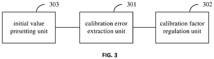
- the terminal provided by the embodiment of the disclosure includes: a calibration error extraction unit 301 and a calibration factor regulation unit 302.
- the calibration error extraction unit 301 is arranged to perform clock calibration according to a calibration factor of an n th calibration period in the nth calibration period, and obtain a calibration error of the n th calibration period.
- the calibration factor regulation unit 302 is arranged to obtain a calibration factor of an ( n + 1 ) th calibration period according to the calibration error and calibration factor of the n th calibration period, where n is a positive integer.
- the calibration period is preset to be at least one DRX time period.
- the terminal may further include an initial value presetting unit 303.
- the initial value presetting unit 303 is arranged to preset a calibration factor of a first calibration period.
- the initial value presetting unit 303 is arranged to obtain a calibration factor according to a theoretical frequency value of a system clock and a theoretical frequency value of a low-frequency clock, and preset the obtained calibration factor as the calibration factor of the first calibration period.
- the initial value presetting unit 303 is arranged to cause the system clock and the low-frequency clock to operate simultaneously and count respectively in a preset time period, calculate a ratio of a count value of a system clock period to a count value of a low-frequency clock period to obtain a calibration factor after the preset time period, and preset the obtained calibration factor as the calibration factor of the first calibration period.
- the calibration error extraction unit 301, the calibration factor regulation unit 302 and the initial value presetting unit 303 may be implemented by a Central Processing Unit (CPU), Micro Processing Unit (MPU), Digital Signal Processor (DSP) or Field-Programmable Gate Array (FPGA) located in the terminal.
- CPU Central Processing Unit
- MPU Micro Processing Unit
- DSP Digital Signal Processor
- FPGA Field-Programmable Gate Array
- the embodiment of the disclosure may be provided as a method, a system or a computer program product. Therefore, the disclosure may adopt a form of hardware embodiment, software embodiment or combined software and hardware embodiment. Moreover, the disclosure may adopt a form of computer program product implemented on one or more computer-available storage media (including, but not limited to, a disk memory, an optical memory and the like) including computer-available program codes.
- a computer-available storage media including, but not limited to, a disk memory, an optical memory and the like
- each flow and/or block in the flowcharts and/or the block diagrams and combinations of the flows and/or blocks in the flowcharts and/or the block diagrams may be implemented by computer program instructions.
- These computer program instructions may be provided for a universal computer, a dedicated computer, an embedded processor or a processor of other programmable data processing equipment to generate a machine, so that a device for realizing a function specified in one flow or more flows in the flowcharts and/or one block or more blocks in the block diagrams is generated by the instructions executed through the computer or the processor of the other programmable data processing equipment.
- These computer program instructions may also be stored in a computer-readable memory capable of guiding the computer or the other programmable data processing equipment to work in a specific manner, so that a product including an instruction device may be generated by the instructions stored in the computer-readable memory, the instruction device realizing the function specified in one flow or many flows in the flowcharts and/or one block or many blocks in the block diagrams.
- These computer program instructions may further be loaded onto the computer or the other programmable data processing equipment, so that a series of operating steps are executed on the computer or the other programmable data processing equipment to generate processing implemented by the computer, and steps for realizing the function specified in one flow or many flows in the flowcharts and/or one block or many blocks in the block diagrams are provided by the instructions executed on the computer or the other programmable data processing equipment.
- an embodiment of the disclosure further provides a computer storage medium, which includes a set of instructions, the instructions being executed to cause at least one processor to execute the abovementioned closed-loop clock calibration method.
Landscapes
- Engineering & Computer Science (AREA)
- Computer Networks & Wireless Communication (AREA)
- Signal Processing (AREA)
- Stabilization Of Oscillater, Synchronisation, Frequency Synthesizers (AREA)
- Synchronisation In Digital Transmission Systems (AREA)
- Position Fixing By Use Of Radio Waves (AREA)
- Power Sources (AREA)
Description
- The disclosure relates to a clock calibration technology in the field of wireless communication, and particularly to a closed-loop clock calibration method, a terminal and a computer storage medium.
- In a wireless cellular communication system, when a terminal in the system executes no service or fewer services, the terminal may usually enter a Discontinuous Reception (DRX) time period. Usually, the DRX time period is divided into two time periods: an active time period and a sleep time period, as shown in
Fig. 1 . The terminal may turn off most of internal operation units when entering the sleep time period. The operation unit includes a system clock which may also be called as a high-frequency clock. At this point, the terminal turns off the high-frequency clock and adopts a low-frequency clock with a lower frequency and lower power consumption to maintain system timing. For example, most of terminals in the wireless cellular communication system usually maintain system timing by adopting low-frequency clocks with a frequency of 32.768kHz. When entering the active time period, the terminal recovers the system timing through the low-frequency clock in the sleep time period at first, and converts the low-frequency clock into a high-frequency clock through multiplying the low-frequency clock by a calibration factor, so as to recover the system timing. Since the low-frequency clock has relatively lower accuracy and stability and cannot perform temperature compensation, the low-frequency clock may be influenced by a factor such as an environment and a temperature. After the terminal recovers the system timing, the system timing may have a calibration deviation, and the terminal further performs frequency and time synchronization, and then may initiate or receive paging. It can be seen that the terminal should regulate the calibration factor to make the recovered system timing more accurate, thereby improving execution efficiency of a subsequent synchronization operation. - In an existing calibration factor regulation manner, a system clock (high-frequency clock) is usually adopted as a calibration clock, to calibrate a low-frequency clock. That is, the high-frequency clock and the low-frequency clock operate simultaneously and count respectively, and after a time period, a ratio of the high-frequency clock to the low-frequency clock is calculated to obtain a calibration factor. However, the high-frequency clock may be influenced by clock jitter. Therefore, the existing calibration factor regulation manner should increase a calibration time to ensure calibration accuracy. The higher the calibration accuracy is, the longer the calibration time is. Usually, the calibration time should be more than 100ms. However, an excessively long calibration time may reduce a sleep time of a terminal in the sleep time period, which may increase standby power consumption of the terminal.
- In view of this, it is desired to provide a closed-loop clock calibration method, a terminal and a computer storage medium, according to embodiments of the disclosure.
- For this purpose, the technical solutions of the disclosure are implemented as follows.
- An embodiment of the disclosure provides a closed-loop clock calibration method. The method includes the following steps.
- In an n th calibration period, clock calibration is performed according to a calibration factor of an nth calibration period, and a calibration error of the n th calibration period is obtained.
- A calibration factor of an (n+1)th calibration period is obtained according to the calibration error and calibration factor of the n th calibration period, where n is a positive integer.
- According to an embodiment, the method may further include a step in which a calibration factor of a first calibration period is preset.
- According to an embodiment, the step of presetting the calibration factor of the first calibration period may include the following steps.
- A calibration factor is obtained according to a theoretical frequency value of a system clock and a theoretical frequency value of a low-frequency clock.
- The obtained calibration factor is preset as the calibration factor of the first calibration period.
- According to an embodiment, the step of presetting the calibration factor of the first calibration period may include the following steps.
- In a preset time period, the system clock and the low-frequency clock are caused to operate simultaneously and count respectively.
- After the preset time period, a ratio of a count value of a system clock period to a count value of a low-frequency clock period is calculated to obtain a calibration factor. The obtained calibration factor is preset as the calibration factor of the first calibration period.
- Specially, the step of, in the n th calibration period, performing clock calibration according to the calibration factor of the n th calibration period and obtaining the calibration error of the nth calibration period may include the following steps.
- In the n th calibration period, the low-frequency clock is converted into converted into the system clock to recover system timing through multiplying low-frequency clock by the calibration factor of the n th calibration period. The calibration error Δt of the n th calibration period is obtained according to the following formula:

- According to an embodiment, the step of obtaining the calibration factor of the (n+1)th calibration period according to the calibration error and calibration factor of the n th calibration period may include the following steps.
- The calibration factor f(n + 1) of the (n+1)th calibration period is derived from the calibration error and calibration factor of the n th calibration period and according to the following formula:

- According to an embodiment, the calibration period may be preset to be at least one DRX time period.
- Based on the method, an embodiment of the disclosure further provides a terminal. The terminal includes: a calibration error extraction unit and a calibration factor regulation unit.
- The calibration error extraction unit is arranged to: in an n th calibration period, perform clock calibration according to a calibration factor of the n th calibration period, and obtain a calibration error of the n th calibration period.
- The calibration factor regulation unit is arranged to obtain a calibration factor of an (n+1)th calibration period according to the calibration error and calibration factor of the n th calibration period, where n is a positive integer.
- According to an embodiment, the terminal may further include an initial value presetting unit.
- The initial value presetting unit is arranged to preset a calibration factor of a first calibration period.
- According to an embodiment, the initial value presetting unit may be further arranged to obtain a calibration factor according to a theoretical frequency value of a system clock and a theoretical frequency value of a low-frequency clock, and preset the obtained calibration factor as the calibration factor of the first calibration period.
- According to an embodiment, the initial value presetting unit may be further arranged to: in a preset time period, cause the system clock and the low-frequency clock to operate simultaneously and count respectively; after the preset time period, calculate a ratio of a count value of a system clock period to a count value of a low-frequency clock period to obtain a calibration factor; and preset the obtained calibration factor as the calibration factor of the first calibration period.
- According to an embodiment, the calibration period may be preset to be at least one DRX time period.
- An embodiment of the disclosure further provides a computer storage medium including a set of instructions. The instructions, when being executed, causes at least one processor to execute the abovementioned closed-loop clock calibration method.
- According to the closed-loop clock calibration method, terminal and computer storage medium provided by the embodiments of the disclosure, in the n th calibration period, the clock calibration is performed according to the calibration factor of the n th calibration period, and the calibration error of the n th calibration period is obtained. The calibration factor of the (n+1)th calibration period is obtained according to the calibration error and calibration factor of the n th calibration period, where n is a positive integer. In this manner, closed-loop clock calibration is performed according to the calibration error, which may not only improve clock calibration accuracy but also reduce standby power consumption of the terminal.
-
-
Fig. 1 is a schematic structure diagram of a DRX time period according to a related technology. -
Fig. 2 is a schematic implementation flowchart of a closed-loop clock calibration method according to an embodiment of the disclosure. -
Fig. 3 is a schematic structure diagram of a terminal according to an embodiment of the disclosure. - According to embodiments of the disclosure, in the n th calibration period, clock calibration is performed according to a calibration factor of an n th calibration period, and a calibration error of the n th calibration period is obtained; and a calibration factor of an (n+1)th calibration period is obtained according to the calibration error and calibration factor of the nth calibration period, where n is a positive integer.
- A specific implementations of the disclosure will be described below with reference to the drawings.
- As shown in
Fig. 2 , a closed-loop clock calibration flow provided by an embodiment of the disclosure includes the following steps. - Step S201: in an n th calibration period, clock calibration is performed according to a calibration factor of the n th calibration period, and a calibration error of the nth calibration period is obtained, where n is a positive integer.
- Here, the calibration period T is usually at least one a Discontinuous Reception (DRX) time period TDRX, TDRX = TActive + TSleep, where TActive is an active time period in the DRX time period TDRX, and TSleep is a sleep time period in the DRX time period TDRX .
- Here, a calibration factor used in a first calibration period is an initial calibration factor, and the initial calibration factor may be preset in the following two manners.
- A first manner: a calibration factor f(1) is derived from a theoretical frequency value of a system clock and a theoretical frequency value of a low-frequency clock according to the following formula:

- The obtained calibration factor f(1) is preset as the calibration factor of the first calibration period.
- A second manner: clock calibration of a preset time period is performed to obtain a calibration factor by virtue of the system clock. A specific implementation process includes the following steps.
- The system clock and the low-frequency clock are caused to operate simultaneously and count respectively in the preset time period.
- A ratio of a count value of a system clock period to a count value of a low-frequency clock period is calculated to obtain a calibration factor after the preset time period.
- The obtained calibration factor is preset as the calibration factor of the first calibration period.
- The step of within the nth calibration period performing clock calibration according to the calibration factor of the n th calibration period and obtaining the calibration error of the n th calibration period will be described below in detail.
- In the nth calibration period, when an active stage is entered, the low-frequency clock of a sleep stage is converted into the system clock through multiplying the low-frequency clock of the sleep stage by the calibration factor of the n th calibration period, thereby recovering system timing in the n th calibration period. The calibration error Δt of the n th calibration period is derived according to the following formula:

- Here, the actual system timing TS may be obtained by a frequency and time synchronization process after the system timing is recovered. There is a conventional means to obtain the actual system timing TS , and the details thereof will not be elaborated.
- It is should be noted that, when Δt>0, i.e., when the timing recovered through the calibration factor of the n th calibration period is earlier than the actual timing, the calibration factor of the n th calibration period should be decreased and the regulated calibration factor is adopted for clock calibration in a next calibration period. When Δt<0, i.e., when the timing recovered through the calibration factor of the n th calibration period is later than the actual timing, the calibration factor of the n th calibration period should be increased and the regulated calibration factor for clock calibration in the next calibration period.
- Step S202: a calibration factor of an (n+1)th calibration period is obtained according to the calibration error and calibration factor of the nth calibration period.
- Specifically, before the (n+1)th calibration period, the calibration factor f(n + 1) of the (n+1) th calibration period is derived from the calibration error and calibration factor of the n th calibration period according to the following formula:

- According to the embodiment of the disclosure, before the (n+1)th calibration period, the calibration factor of the n th calibration period is regulated according to the calibration error of the n th calibration period, so as to obtain the calibration factor of the (n+1)th calibration period. The calibration factor of the (n+1)th calibration period is adopted for clock calibration in the (n+1)th calibration period, and so on, to implement closed-loop clock calibration. In this manner, closed-loop clock calibration is performed according to the calibration error, and thus clock calibration accuracy can be improved. Moreover, since the calibration method according to the embodiment of the disclose is independent of the system clock, the problem of excessively long calibration time in the conventional art is solved, and thus standby power consumption of a terminal is reduced.
- In order to make the embodiment of the disclosure to be clearer, a data exchange flow in the embodiment of the disclosure will be described below in detail with a specific embodiment.
- A terminal presets a calibration period T to be a DRX time period TDRX, and presets a calibration factor of a first calibration period to be f(1).
- In the first calibration period, when an active stage is entered, a low-frequency clock of a sleep stage is converted into a system clock through multiplying the low-frequency clock of the sleep stage by f(1), so as to recover system timing. Then, a calibration error Δt 1 caused by clock calibration with f(1) is calculated from actual system timing T S1 and the system timing T C1 recovered through f(1), according to Δt 1 = T S1 - T C1 .
- Then, before a second calibration period, f(1) is corrected to obtain f(2) according to the calibration error Δt 1. The f(2) is adopted for clock calibration in the second calibration period.
- In the second calibration period, when an active stage is entered, a low-frequency clock of a sleep stage is converted into a system clock through multiplying the low frequency clock of the sleep stage by f(2), so as to recover system timing. Then, a calibration error Δt 2 caused by clock calibration with f(2) is calculated from actual system timing T S2 and the system timing T C2 recovered through f(2), according to Δt 2 = T S2 - T C2.
- Then, before a third calibration period, f(2) is corrected to obtain f(3) according to the calibration error Δt 2. The f(3) is adopted for clock calibration in the third calibration period.
- In this manner, clock calibration is performed according to a corrected calibration factor of a previous calibration period in an n th calibration period, and a calibration error of the n th calibration period is obtained. A calibration factor of the n th calibration period is corrected according to the calibration error of the nth calibration period, so as to obtain a corrected calibration factor. The corrected calibration factor is adopted for clock calibration in a next calibration period. In this way, the closed-loop clock calibration can be implemented.
- In order to implement the abovementioned method, an embodiment of the disclosure provides a terminal. A principle of the terminal for solving the problem is similar to the method, so that an implementation process and implementation principle of the terminal may refer to descriptions about an implementation process and implementation principle of the method, and repeated parts will not be elaborated.
- As shown in
Fig. 3 , the terminal provided by the embodiment of the disclosure includes: a calibrationerror extraction unit 301 and a calibrationfactor regulation unit 302. - The calibration
error extraction unit 301 is arranged to perform clock calibration according to a calibration factor of an n th calibration period in the nth calibration period, and obtain a calibration error of the n th calibration period. - The calibration
factor regulation unit 302 is arranged to obtain a calibration factor of an (n+1)th calibration period according to the calibration error and calibration factor of the n th calibration period, where n is a positive integer. - The calibration period is preset to be at least one DRX time period.
- The division of the above function units or modules is merely a preferred implementation provided by the embodiment of the disclosure, and is not intended to limit the disclosure.
- Furthermore, the terminal may further include an initial
value presetting unit 303. - The initial
value presetting unit 303 is arranged to preset a calibration factor of a first calibration period. - Specially, the initial
value presetting unit 303 is arranged to obtain a calibration factor according to a theoretical frequency value of a system clock and a theoretical frequency value of a low-frequency clock, and preset the obtained calibration factor as the calibration factor of the first calibration period. - Specially, the initial
value presetting unit 303 is arranged to cause the system clock and the low-frequency clock to operate simultaneously and count respectively in a preset time period, calculate a ratio of a count value of a system clock period to a count value of a low-frequency clock period to obtain a calibration factor after the preset time period, and preset the obtained calibration factor as the calibration factor of the first calibration period. - In practice, the calibration
error extraction unit 301, the calibrationfactor regulation unit 302 and the initialvalue presetting unit 303 may be implemented by a Central Processing Unit (CPU), Micro Processing Unit (MPU), Digital Signal Processor (DSP) or Field-Programmable Gate Array (FPGA) located in the terminal. - Those skilled in the art should know that the embodiment of the disclosure may be provided as a method, a system or a computer program product. Therefore, the disclosure may adopt a form of hardware embodiment, software embodiment or combined software and hardware embodiment. Moreover, the disclosure may adopt a form of computer program product implemented on one or more computer-available storage media (including, but not limited to, a disk memory, an optical memory and the like) including computer-available program codes.
- The disclosure is described with reference to flowcharts and/or block diagrams of the method, equipment (system) and computer program product according to the embodiment of the disclosure. It should be understood that each flow and/or block in the flowcharts and/or the block diagrams and combinations of the flows and/or blocks in the flowcharts and/or the block diagrams may be implemented by computer program instructions. These computer program instructions may be provided for a universal computer, a dedicated computer, an embedded processor or a processor of other programmable data processing equipment to generate a machine, so that a device for realizing a function specified in one flow or more flows in the flowcharts and/or one block or more blocks in the block diagrams is generated by the instructions executed through the computer or the processor of the other programmable data processing equipment.
- These computer program instructions may also be stored in a computer-readable memory capable of guiding the computer or the other programmable data processing equipment to work in a specific manner, so that a product including an instruction device may be generated by the instructions stored in the computer-readable memory, the instruction device realizing the function specified in one flow or many flows in the flowcharts and/or one block or many blocks in the block diagrams.
- These computer program instructions may further be loaded onto the computer or the other programmable data processing equipment, so that a series of operating steps are executed on the computer or the other programmable data processing equipment to generate processing implemented by the computer, and steps for realizing the function specified in one flow or many flows in the flowcharts and/or one block or many blocks in the block diagrams are provided by the instructions executed on the computer or the other programmable data processing equipment.
- On such a basis, an embodiment of the disclosure further provides a computer storage medium, which includes a set of instructions, the instructions being executed to cause at least one processor to execute the abovementioned closed-loop clock calibration method.
- The method of the disclosure is not limited to the embodiments in the detailed description, and other implementation modes obtained by those skilled in the art according to the technical solutions of the disclosure shall also fall within the scope of technical innovation of the disclosure.
- Obviously, those skilled in the art may make various modifications and transformations to the disclosure without departing from the spirit and scope of the disclosure. Therefore, if these modifications and transformations of the disclosure fall within the scope of the claims of the disclosure and an equivalent technology thereof, the disclosure is also intended to include these modifications and transformations.
Claims (13)
- A closed-loop clock calibration method, comprising:in an n th calibration period, performing clock calibration according to a calibration factor of the n th calibration period, and obtaining a calibration error of the n th calibration period; andobtaining a calibration factor of an (n+1)th calibration period according to the calibration error and the calibration factor of the n th calibration period, wherein n is a positive integer.
- The method according to claim 1, further comprising:presetting a calibration factor of a first calibration period.
- The method according to claim 2, wherein presetting the calibration factor of the first calibration period comprises:obtaining a calibration factor according to a theoretical frequency value of a system clock and a theoretical frequency value of a low-frequency clock; andpresetting the obtained calibration factor as the calibration factor of the first calibration period.
- The method according to claim 2, wherein presetting the calibration factor of the first calibration period comprises:in a preset time period, causing the system clock and the low-frequency clock to operate simultaneously and count respectively;after the preset time period, calculating a ratio of a count value of a system clock period to a count value of a low-frequency clock period to obtain a calibration factor; and presetting the obtained calibration factor as the calibration factor of the first calibration period.
- The method according to claim 1, wherein, in the n th calibration period, performing clock calibration according to the calibration factor of the n th calibration period and obtaining the calibration error of the n th calibration period comprises:in the n th calibration period, converting the low-frequency clock into the system clock through multiplying the low-frequency clock by the calibration factor of the n th calibration period, so as to recover system timing; and obtaining the calibration error Δt of the n th calibration period according to the following formula:

- The method according to claim 1, wherein obtaining the calibration factor of the (n+1)th calibration period according to the calibration error and calibration factor of the n th calibration period comprises:deriving the calibration factor f(n + 1) of the (n+1)th calibration period from the calibration error and calibration factor of the n th calibration period according to the following formula:

- The method according to any one of claims 1-6, wherein the calibration period is preset to be at least one DRX time period.
- A terminal, comprising: a calibration error extraction unit and a calibration factor regulation unit, whereinthe calibration error extraction unit is arranged to, in an n th calibration period, perform clock calibration according to a calibration factor of the n th calibration period, and obtain a calibration error of the n th calibration period; andthe calibration factor regulation unit is arranged to obtain a calibration factor of an (n+1)th calibration period according to the calibration error and calibration factor of the n th calibration period, wherein n is a positive integer.
- The terminal according to claim 8, further comprising:an initial value presetting unit, arranged to preset a calibration factor of a first calibration period.
- The terminal according to claim 9, wherein the initial value presetting unit is further arranged to obtain a calibration factor according to a theoretical frequency value of a system clock and a theoretical frequency value of a low-frequency clock, and preset the obtained calibration factor as the calibration factor of the first calibration period.
- The terminal according to claim 9, wherein the initial value presetting unit is further arranged to: in a preset time period, cause the system clock and the low-frequency clock to operate simultaneously and count respectively; after the preset time period, calculate a ratio of a count value of a system clock period to a count value of a low-frequency clock period to obtain a calibration factor; and preset the obtained calibration factor as the calibration factor of the first calibration period.
- The terminal according to any one of claims 8-11, wherein the calibration period is preset to be at least one Discontinuous Reception, DRX, time period.
- A computer storage medium comprising a set of instructions, wherein the instructions, when being executed, cause at least one processor to execute the closed-loop clock calibration method according to any one of claims 1-7.
Applications Claiming Priority (2)
| Application Number | Priority Date | Filing Date | Title |
|---|---|---|---|
| CN201510027790.7A CN105873190B (en) | 2015-01-20 | 2015-01-20 | A closed-loop clock calibration method and terminal |
| PCT/CN2015/084794 WO2016115855A1 (en) | 2015-01-20 | 2015-07-22 | Closed-loop clock calibration method, terminal and computer storage medium |
Publications (3)
| Publication Number | Publication Date |
|---|---|
| EP3249978A1 true EP3249978A1 (en) | 2017-11-29 |
| EP3249978A4 EP3249978A4 (en) | 2018-01-24 |
| EP3249978B1 EP3249978B1 (en) | 2019-02-27 |
Family
ID=56416359
Family Applications (1)
| Application Number | Title | Priority Date | Filing Date |
|---|---|---|---|
| EP15878526.1A Active EP3249978B1 (en) | 2015-01-20 | 2015-07-22 | Closed-loop clock calibration method, terminal and computer storage medium |
Country Status (4)
| Country | Link |
|---|---|
| US (1) | US10172093B2 (en) |
| EP (1) | EP3249978B1 (en) |
| CN (1) | CN105873190B (en) |
| WO (1) | WO2016115855A1 (en) |
Families Citing this family (4)
| Publication number | Priority date | Publication date | Assignee | Title |
|---|---|---|---|---|
| US20180331255A1 (en) * | 2017-05-12 | 2018-11-15 | X Development Llc | Fabrication of ultraviolet light emitting diode with tunnel junction |
| CN107817869A (en) * | 2017-11-01 | 2018-03-20 | 中颖电子股份有限公司 | A kind of Bluetooth chip framework and the clock control method based on low-power consumption bluetooth chip |
| CN108230660B (en) * | 2018-01-09 | 2020-08-25 | 广东美的制冷设备有限公司 | Control method and control device, storage medium and remote controller |
| TWI857595B (en) | 2023-05-05 | 2024-10-01 | 瑞昱半導體股份有限公司 | Clock correction method and clock correction circuit |
Family Cites Families (10)
| Publication number | Priority date | Publication date | Assignee | Title |
|---|---|---|---|---|
| US7197341B2 (en) * | 2003-12-22 | 2007-03-27 | Interdigital Technology Corporation | Precise sleep timer using a low-cost and low-accuracy clock |
| CN1874566B (en) * | 2005-11-25 | 2010-07-21 | 上海宣普实业有限公司 | Clock calibration method and device |
| CN101064898B (en) | 2006-04-29 | 2012-05-23 | 华为技术有限公司 | Method and device for measuring channel in long term evolution system |
| CN100588280C (en) * | 2007-07-24 | 2010-02-03 | 北京天碁科技有限公司 | A method and device for calibrating sleep clock of TD-SCDMA terminal |
| US8135553B2 (en) * | 2008-07-31 | 2012-03-13 | Mediatek Inc. | Method for clock calibration |
| CN101541073B (en) * | 2009-04-28 | 2011-01-05 | 安徽省电力科学研究院 | Compensation Method for Frequency Error of Crystal Oscillator in Wireless Sensor Network Nodes |
| CN101959298B (en) | 2009-07-17 | 2015-03-25 | 联芯科技有限公司 | Method and device for calibrating slow timing clock and terminal |
| US8560875B2 (en) * | 2009-09-17 | 2013-10-15 | Avago Technologies General Ip (Singapore) Pte. Ltd. | Apparatus for clock calibrating a less precise second clock signal with a more precise first clock signal wherein the first clock signal is inactive during a sniff mode and the second clock signal is active during a sniff mode |
| CN102540868B (en) * | 2010-12-31 | 2016-05-04 | 重庆重邮信科通信技术有限公司 | A kind of slow clock crystal frequency compensation method of mobile communication terminal and device |
| WO2011113377A2 (en) * | 2011-04-26 | 2011-09-22 | 华为技术有限公司 | Method and apparatus for calibrating low frequency clock |
-
2015
- 2015-01-20 CN CN201510027790.7A patent/CN105873190B/en active Active
- 2015-07-22 EP EP15878526.1A patent/EP3249978B1/en active Active
- 2015-07-22 US US15/545,035 patent/US10172093B2/en active Active
- 2015-07-22 WO PCT/CN2015/084794 patent/WO2016115855A1/en not_active Ceased
Also Published As
| Publication number | Publication date |
|---|---|
| CN105873190A (en) | 2016-08-17 |
| CN105873190B (en) | 2019-04-30 |
| EP3249978A4 (en) | 2018-01-24 |
| US10172093B2 (en) | 2019-01-01 |
| WO2016115855A1 (en) | 2016-07-28 |
| EP3249978B1 (en) | 2019-02-27 |
| US20180007635A1 (en) | 2018-01-04 |
Similar Documents
| Publication | Publication Date | Title |
|---|---|---|
| EP3249978B1 (en) | Closed-loop clock calibration method, terminal and computer storage medium | |
| EP2984900B1 (en) | System frame number synchronization | |
| US11963227B2 (en) | Enhanced timing advanced filtering | |
| CN107113891A (en) | The measurement of increased main plot that network is controlled and based on deployment | |
| KR20160083101A (en) | System and methods of reducing energy consumption by synchronizing sensors | |
| CN104683040B (en) | The calibration method and calibrating installation of frequency synthesizer in communication terminal | |
| WO2012107912A1 (en) | Method and apparatus for configuring transmission of a power headroom report in carrier aggregation systems | |
| CN104640179A (en) | Communication device and frequency offset correction method | |
| CN107678779A (en) | A kind of timed task performs method and electronic equipment | |
| CN108054766A (en) | A kind of setting method, system and the device of Automatic Generation Control frequency bias coefficient | |
| CN101090547A (en) | Method and device for calibrating sleep clock of TD-SCDMA terminal | |
| JP6015195B2 (en) | Communication apparatus and transmission power control method | |
| US20160212723A1 (en) | Synchronization method and apparatus | |
| CN101083815B (en) | Method and apparatus for realizing mobile terminal clock relation track | |
| CN105573458B (en) | Information processing method and electronic equipment | |
| JP2012047705A (en) | Time correction device and control method | |
| JP6394452B2 (en) | Wireless communication apparatus, wireless communication method, and program | |
| CN106301644B (en) | A kind of synchronous method and apparatus of voice | |
| US20160135215A1 (en) | Long term evolution network system and data transmission scheduling method thereof | |
| CN107863973A (en) | A kind of power calibration method and apparatus | |
| CN113543289A (en) | Communication device and method for dynamically adjusting wake-up time | |
| CN105116712A (en) | Method for automatically calibrating built-in crystal oscillator | |
| CN110876178B (en) | 32K clock calibration method and device | |
| CN105471446A (en) | Power amplification processing method and device | |
| US20230359500A1 (en) | Computing system management |
Legal Events
| Date | Code | Title | Description |
|---|---|---|---|
| STAA | Information on the status of an ep patent application or granted ep patent |
Free format text: STATUS: THE INTERNATIONAL PUBLICATION HAS BEEN MADE |
|
| PUAI | Public reference made under article 153(3) epc to a published international application that has entered the european phase |
Free format text: ORIGINAL CODE: 0009012 |
|
| STAA | Information on the status of an ep patent application or granted ep patent |
Free format text: STATUS: REQUEST FOR EXAMINATION WAS MADE |
|
| 17P | Request for examination filed |
Effective date: 20170818 |
|
| AK | Designated contracting states |
Kind code of ref document: A1 Designated state(s): AL AT BE BG CH CY CZ DE DK EE ES FI FR GB GR HR HU IE IS IT LI LT LU LV MC MK MT NL NO PL PT RO RS SE SI SK SM TR |
|
| AX | Request for extension of the european patent |
Extension state: BA ME |
|
| A4 | Supplementary search report drawn up and despatched |
Effective date: 20171221 |
|
| RIC1 | Information provided on ipc code assigned before grant |
Ipc: H04W 52/02 20090101AFI20171215BHEP |
|
| DAV | Request for validation of the european patent (deleted) | ||
| DAX | Request for extension of the european patent (deleted) | ||
| GRAP | Despatch of communication of intention to grant a patent |
Free format text: ORIGINAL CODE: EPIDOSNIGR1 |
|
| STAA | Information on the status of an ep patent application or granted ep patent |
Free format text: STATUS: GRANT OF PATENT IS INTENDED |
|
| INTG | Intention to grant announced |
Effective date: 20181012 |
|
| GRAS | Grant fee paid |
Free format text: ORIGINAL CODE: EPIDOSNIGR3 |
|
| GRAA | (expected) grant |
Free format text: ORIGINAL CODE: 0009210 |
|
| STAA | Information on the status of an ep patent application or granted ep patent |
Free format text: STATUS: THE PATENT HAS BEEN GRANTED |
|
| AK | Designated contracting states |
Kind code of ref document: B1 Designated state(s): AL AT BE BG CH CY CZ DE DK EE ES FI FR GB GR HR HU IE IS IT LI LT LU LV MC MK MT NL NO PL PT RO RS SE SI SK SM TR |
|
| REG | Reference to a national code |
Ref country code: GB Ref legal event code: FG4D |
|
| REG | Reference to a national code |
Ref country code: CH Ref legal event code: EP |
|
| REG | Reference to a national code |
Ref country code: AT Ref legal event code: REF Ref document number: 1103215 Country of ref document: AT Kind code of ref document: T Effective date: 20190315 |
|
| REG | Reference to a national code |
Ref country code: IE Ref legal event code: FG4D |
|
| REG | Reference to a national code |
Ref country code: DE Ref legal event code: R096 Ref document number: 602015025643 Country of ref document: DE |
|
| REG | Reference to a national code |
Ref country code: NL Ref legal event code: MP Effective date: 20190227 |
|
| REG | Reference to a national code |
Ref country code: LT Ref legal event code: MG4D |
|
| PG25 | Lapsed in a contracting state [announced via postgrant information from national office to epo] |
Ref country code: NO Free format text: LAPSE BECAUSE OF FAILURE TO SUBMIT A TRANSLATION OF THE DESCRIPTION OR TO PAY THE FEE WITHIN THE PRESCRIBED TIME-LIMIT Effective date: 20190527 Ref country code: NL Free format text: LAPSE BECAUSE OF FAILURE TO SUBMIT A TRANSLATION OF THE DESCRIPTION OR TO PAY THE FEE WITHIN THE PRESCRIBED TIME-LIMIT Effective date: 20190227 Ref country code: LT Free format text: LAPSE BECAUSE OF FAILURE TO SUBMIT A TRANSLATION OF THE DESCRIPTION OR TO PAY THE FEE WITHIN THE PRESCRIBED TIME-LIMIT Effective date: 20190227 Ref country code: PT Free format text: LAPSE BECAUSE OF FAILURE TO SUBMIT A TRANSLATION OF THE DESCRIPTION OR TO PAY THE FEE WITHIN THE PRESCRIBED TIME-LIMIT Effective date: 20190627 Ref country code: SE Free format text: LAPSE BECAUSE OF FAILURE TO SUBMIT A TRANSLATION OF THE DESCRIPTION OR TO PAY THE FEE WITHIN THE PRESCRIBED TIME-LIMIT Effective date: 20190227 Ref country code: FI Free format text: LAPSE BECAUSE OF FAILURE TO SUBMIT A TRANSLATION OF THE DESCRIPTION OR TO PAY THE FEE WITHIN THE PRESCRIBED TIME-LIMIT Effective date: 20190227 |
|
| REG | Reference to a national code |
Ref country code: GR Ref legal event code: EP Ref document number: 20190401174 Country of ref document: GR Effective date: 20190620 |
|
| PG25 | Lapsed in a contracting state [announced via postgrant information from national office to epo] |
Ref country code: LV Free format text: LAPSE BECAUSE OF FAILURE TO SUBMIT A TRANSLATION OF THE DESCRIPTION OR TO PAY THE FEE WITHIN THE PRESCRIBED TIME-LIMIT Effective date: 20190227 Ref country code: RS Free format text: LAPSE BECAUSE OF FAILURE TO SUBMIT A TRANSLATION OF THE DESCRIPTION OR TO PAY THE FEE WITHIN THE PRESCRIBED TIME-LIMIT Effective date: 20190227 Ref country code: IS Free format text: LAPSE BECAUSE OF FAILURE TO SUBMIT A TRANSLATION OF THE DESCRIPTION OR TO PAY THE FEE WITHIN THE PRESCRIBED TIME-LIMIT Effective date: 20190627 Ref country code: BG Free format text: LAPSE BECAUSE OF FAILURE TO SUBMIT A TRANSLATION OF THE DESCRIPTION OR TO PAY THE FEE WITHIN THE PRESCRIBED TIME-LIMIT Effective date: 20190527 Ref country code: HR Free format text: LAPSE BECAUSE OF FAILURE TO SUBMIT A TRANSLATION OF THE DESCRIPTION OR TO PAY THE FEE WITHIN THE PRESCRIBED TIME-LIMIT Effective date: 20190227 |
|
| REG | Reference to a national code |
Ref country code: AT Ref legal event code: MK05 Ref document number: 1103215 Country of ref document: AT Kind code of ref document: T Effective date: 20190227 |
|
| PG25 | Lapsed in a contracting state [announced via postgrant information from national office to epo] |
Ref country code: DK Free format text: LAPSE BECAUSE OF FAILURE TO SUBMIT A TRANSLATION OF THE DESCRIPTION OR TO PAY THE FEE WITHIN THE PRESCRIBED TIME-LIMIT Effective date: 20190227 Ref country code: ES Free format text: LAPSE BECAUSE OF FAILURE TO SUBMIT A TRANSLATION OF THE DESCRIPTION OR TO PAY THE FEE WITHIN THE PRESCRIBED TIME-LIMIT Effective date: 20190227 Ref country code: AL Free format text: LAPSE BECAUSE OF FAILURE TO SUBMIT A TRANSLATION OF THE DESCRIPTION OR TO PAY THE FEE WITHIN THE PRESCRIBED TIME-LIMIT Effective date: 20190227 Ref country code: RO Free format text: LAPSE BECAUSE OF FAILURE TO SUBMIT A TRANSLATION OF THE DESCRIPTION OR TO PAY THE FEE WITHIN THE PRESCRIBED TIME-LIMIT Effective date: 20190227 Ref country code: SK Free format text: LAPSE BECAUSE OF FAILURE TO SUBMIT A TRANSLATION OF THE DESCRIPTION OR TO PAY THE FEE WITHIN THE PRESCRIBED TIME-LIMIT Effective date: 20190227 Ref country code: CZ Free format text: LAPSE BECAUSE OF FAILURE TO SUBMIT A TRANSLATION OF THE DESCRIPTION OR TO PAY THE FEE WITHIN THE PRESCRIBED TIME-LIMIT Effective date: 20190227 Ref country code: EE Free format text: LAPSE BECAUSE OF FAILURE TO SUBMIT A TRANSLATION OF THE DESCRIPTION OR TO PAY THE FEE WITHIN THE PRESCRIBED TIME-LIMIT Effective date: 20190227 |
|
| REG | Reference to a national code |
Ref country code: DE Ref legal event code: R097 Ref document number: 602015025643 Country of ref document: DE |
|
| PG25 | Lapsed in a contracting state [announced via postgrant information from national office to epo] |
Ref country code: SM Free format text: LAPSE BECAUSE OF FAILURE TO SUBMIT A TRANSLATION OF THE DESCRIPTION OR TO PAY THE FEE WITHIN THE PRESCRIBED TIME-LIMIT Effective date: 20190227 Ref country code: PL Free format text: LAPSE BECAUSE OF FAILURE TO SUBMIT A TRANSLATION OF THE DESCRIPTION OR TO PAY THE FEE WITHIN THE PRESCRIBED TIME-LIMIT Effective date: 20190227 |
|
| PG25 | Lapsed in a contracting state [announced via postgrant information from national office to epo] |
Ref country code: AT Free format text: LAPSE BECAUSE OF FAILURE TO SUBMIT A TRANSLATION OF THE DESCRIPTION OR TO PAY THE FEE WITHIN THE PRESCRIBED TIME-LIMIT Effective date: 20190227 |
|
| PLBE | No opposition filed within time limit |
Free format text: ORIGINAL CODE: 0009261 |
|
| STAA | Information on the status of an ep patent application or granted ep patent |
Free format text: STATUS: NO OPPOSITION FILED WITHIN TIME LIMIT |
|
| 26N | No opposition filed |
Effective date: 20191128 |
|
| PG25 | Lapsed in a contracting state [announced via postgrant information from national office to epo] |
Ref country code: MC Free format text: LAPSE BECAUSE OF FAILURE TO SUBMIT A TRANSLATION OF THE DESCRIPTION OR TO PAY THE FEE WITHIN THE PRESCRIBED TIME-LIMIT Effective date: 20190227 Ref country code: SI Free format text: LAPSE BECAUSE OF FAILURE TO SUBMIT A TRANSLATION OF THE DESCRIPTION OR TO PAY THE FEE WITHIN THE PRESCRIBED TIME-LIMIT Effective date: 20190227 |
|
| REG | Reference to a national code |
Ref country code: CH Ref legal event code: PL |
|
| PG25 | Lapsed in a contracting state [announced via postgrant information from national office to epo] |
Ref country code: TR Free format text: LAPSE BECAUSE OF FAILURE TO SUBMIT A TRANSLATION OF THE DESCRIPTION OR TO PAY THE FEE WITHIN THE PRESCRIBED TIME-LIMIT Effective date: 20190227 |
|
| REG | Reference to a national code |
Ref country code: BE Ref legal event code: MM Effective date: 20190731 |
|
| PG25 | Lapsed in a contracting state [announced via postgrant information from national office to epo] |
Ref country code: LI Free format text: LAPSE BECAUSE OF NON-PAYMENT OF DUE FEES Effective date: 20190731 Ref country code: LU Free format text: LAPSE BECAUSE OF NON-PAYMENT OF DUE FEES Effective date: 20190722 Ref country code: CH Free format text: LAPSE BECAUSE OF NON-PAYMENT OF DUE FEES Effective date: 20190731 Ref country code: BE Free format text: LAPSE BECAUSE OF NON-PAYMENT OF DUE FEES Effective date: 20190731 |
|
| PG25 | Lapsed in a contracting state [announced via postgrant information from national office to epo] |
Ref country code: FR Free format text: LAPSE BECAUSE OF NON-PAYMENT OF DUE FEES Effective date: 20190731 |
|
| PG25 | Lapsed in a contracting state [announced via postgrant information from national office to epo] |
Ref country code: IE Free format text: LAPSE BECAUSE OF NON-PAYMENT OF DUE FEES Effective date: 20190722 |
|
| PG25 | Lapsed in a contracting state [announced via postgrant information from national office to epo] |
Ref country code: CY Free format text: LAPSE BECAUSE OF FAILURE TO SUBMIT A TRANSLATION OF THE DESCRIPTION OR TO PAY THE FEE WITHIN THE PRESCRIBED TIME-LIMIT Effective date: 20190227 |
|
| PG25 | Lapsed in a contracting state [announced via postgrant information from national office to epo] |
Ref country code: HU Free format text: LAPSE BECAUSE OF FAILURE TO SUBMIT A TRANSLATION OF THE DESCRIPTION OR TO PAY THE FEE WITHIN THE PRESCRIBED TIME-LIMIT; INVALID AB INITIO Effective date: 20150722 Ref country code: MT Free format text: LAPSE BECAUSE OF FAILURE TO SUBMIT A TRANSLATION OF THE DESCRIPTION OR TO PAY THE FEE WITHIN THE PRESCRIBED TIME-LIMIT Effective date: 20190227 |
|
| PG25 | Lapsed in a contracting state [announced via postgrant information from national office to epo] |
Ref country code: MK Free format text: LAPSE BECAUSE OF FAILURE TO SUBMIT A TRANSLATION OF THE DESCRIPTION OR TO PAY THE FEE WITHIN THE PRESCRIBED TIME-LIMIT Effective date: 20190227 |
|
| PGFP | Annual fee paid to national office [announced via postgrant information from national office to epo] |
Ref country code: GB Payment date: 20250529 Year of fee payment: 11 |
|
| PGFP | Annual fee paid to national office [announced via postgrant information from national office to epo] |
Ref country code: GR Payment date: 20250618 Year of fee payment: 11 |
|
| PGFP | Annual fee paid to national office [announced via postgrant information from national office to epo] |
Ref country code: DE Payment date: 20250604 Year of fee payment: 11 |
|
| PGFP | Annual fee paid to national office [announced via postgrant information from national office to epo] |
Ref country code: IT Payment date: 20250623 Year of fee payment: 11 |