EP3249942A1 - Apparatus and method for wirelessly managing aircraft health data - Google Patents
Apparatus and method for wirelessly managing aircraft health data Download PDFInfo
- Publication number
- EP3249942A1 EP3249942A1 EP17170251.7A EP17170251A EP3249942A1 EP 3249942 A1 EP3249942 A1 EP 3249942A1 EP 17170251 A EP17170251 A EP 17170251A EP 3249942 A1 EP3249942 A1 EP 3249942A1
- Authority
- EP
- European Patent Office
- Prior art keywords
- wireless
- monitoring device
- aircraft
- condition monitoring
- wireless network
- Prior art date
- Legal status (The legal status is an assumption and is not a legal conclusion. Google has not performed a legal analysis and makes no representation as to the accuracy of the status listed.)
- Granted
Links
Images




Classifications
-
- G—PHYSICS
- G07—CHECKING-DEVICES
- G07C—TIME OR ATTENDANCE REGISTERS; REGISTERING OR INDICATING THE WORKING OF MACHINES; GENERATING RANDOM NUMBERS; VOTING OR LOTTERY APPARATUS; ARRANGEMENTS, SYSTEMS OR APPARATUS FOR CHECKING NOT PROVIDED FOR ELSEWHERE
- G07C5/00—Registering or indicating the working of vehicles
- G07C5/08—Registering or indicating performance data other than driving, working, idle, or waiting time, with or without registering driving, working, idle or waiting time
- G07C5/0808—Diagnosing performance data
-
- B—PERFORMING OPERATIONS; TRANSPORTING
- B64—AIRCRAFT; AVIATION; COSMONAUTICS
- B64F—GROUND OR AIRCRAFT-CARRIER-DECK INSTALLATIONS SPECIALLY ADAPTED FOR USE IN CONNECTION WITH AIRCRAFT; DESIGNING, MANUFACTURING, ASSEMBLING, CLEANING, MAINTAINING OR REPAIRING AIRCRAFT, NOT OTHERWISE PROVIDED FOR; HANDLING, TRANSPORTING, TESTING OR INSPECTING AIRCRAFT COMPONENTS, NOT OTHERWISE PROVIDED FOR
- B64F5/00—Designing, manufacturing, assembling, cleaning, maintaining or repairing aircraft, not otherwise provided for; Handling, transporting, testing or inspecting aircraft components, not otherwise provided for
- B64F5/60—Testing or inspecting aircraft components or systems
-
- G—PHYSICS
- G07—CHECKING-DEVICES
- G07C—TIME OR ATTENDANCE REGISTERS; REGISTERING OR INDICATING THE WORKING OF MACHINES; GENERATING RANDOM NUMBERS; VOTING OR LOTTERY APPARATUS; ARRANGEMENTS, SYSTEMS OR APPARATUS FOR CHECKING NOT PROVIDED FOR ELSEWHERE
- G07C5/00—Registering or indicating the working of vehicles
- G07C5/008—Registering or indicating the working of vehicles communicating information to a remotely located station
-
- G—PHYSICS
- G07—CHECKING-DEVICES
- G07C—TIME OR ATTENDANCE REGISTERS; REGISTERING OR INDICATING THE WORKING OF MACHINES; GENERATING RANDOM NUMBERS; VOTING OR LOTTERY APPARATUS; ARRANGEMENTS, SYSTEMS OR APPARATUS FOR CHECKING NOT PROVIDED FOR ELSEWHERE
- G07C5/00—Registering or indicating the working of vehicles
- G07C5/08—Registering or indicating performance data other than driving, working, idle, or waiting time, with or without registering driving, working, idle or waiting time
- G07C5/0841—Registering performance data
- G07C5/085—Registering performance data using electronic data carriers
-
- H—ELECTRICITY
- H04—ELECTRIC COMMUNICATION TECHNIQUE
- H04Q—SELECTING
- H04Q9/00—Arrangements in telecontrol or telemetry systems for selectively calling a substation from a main station, in which substation desired apparatus is selected for applying a control signal thereto or for obtaining measured values therefrom
-
- H—ELECTRICITY
- H04—ELECTRIC COMMUNICATION TECHNIQUE
- H04W—WIRELESS COMMUNICATION NETWORKS
- H04W24/00—Supervisory, monitoring or testing arrangements
- H04W24/04—Arrangements for maintaining operational condition
-
- H—ELECTRICITY
- H04—ELECTRIC COMMUNICATION TECHNIQUE
- H04W—WIRELESS COMMUNICATION NETWORKS
- H04W24/00—Supervisory, monitoring or testing arrangements
- H04W24/08—Testing, supervising or monitoring using real traffic
-
- H—ELECTRICITY
- H04—ELECTRIC COMMUNICATION TECHNIQUE
- H04W—WIRELESS COMMUNICATION NETWORKS
- H04W72/00—Local resource management
- H04W72/50—Allocation or scheduling criteria for wireless resources
- H04W72/56—Allocation or scheduling criteria for wireless resources based on priority criteria
-
- H—ELECTRICITY
- H04—ELECTRIC COMMUNICATION TECHNIQUE
- H04W—WIRELESS COMMUNICATION NETWORKS
- H04W84/00—Network topologies
- H04W84/02—Hierarchically pre-organised networks, e.g. paging networks, cellular networks, WLAN [Wireless Local Area Network] or WLL [Wireless Local Loop]
- H04W84/10—Small scale networks; Flat hierarchical networks
- H04W84/12—WLAN [Wireless Local Area Networks]
-
- B—PERFORMING OPERATIONS; TRANSPORTING
- B64—AIRCRAFT; AVIATION; COSMONAUTICS
- B64D—EQUIPMENT FOR FITTING IN OR TO AIRCRAFT; FLIGHT SUITS; PARACHUTES; ARRANGEMENT OR MOUNTING OF POWER PLANTS OR PROPULSION TRANSMISSIONS IN AIRCRAFT
- B64D45/00—Aircraft indicators or protectors not otherwise provided for
- B64D2045/0085—Devices for aircraft health monitoring, e.g. monitoring flutter or vibration
-
- H—ELECTRICITY
- H04—ELECTRIC COMMUNICATION TECHNIQUE
- H04Q—SELECTING
- H04Q2209/00—Arrangements in telecontrol or telemetry systems
- H04Q2209/40—Arrangements in telecontrol or telemetry systems using a wireless architecture
-
- H—ELECTRICITY
- H04—ELECTRIC COMMUNICATION TECHNIQUE
- H04Q—SELECTING
- H04Q2209/00—Arrangements in telecontrol or telemetry systems
- H04Q2209/70—Arrangements in the main station, i.e. central controller
- H04Q2209/75—Arrangements in the main station, i.e. central controller by polling or interrogating the sub-stations
-
- H—ELECTRICITY
- H04—ELECTRIC COMMUNICATION TECHNIQUE
- H04Q—SELECTING
- H04Q2209/00—Arrangements in telecontrol or telemetry systems
- H04Q2209/80—Arrangements in the sub-station, i.e. sensing device
- H04Q2209/82—Arrangements in the sub-station, i.e. sensing device where the sensing device takes the initiative of sending data
Definitions
- aircraft have several components within, for example, the passenger cabin that are monitored for fault diagnosis.
- each of the monitored aircraft cabin components are connected to a data collection unit, such as a centralized data recorder, using wires.
- the wires connecting each monitored aircraft cabin component to the centralized data recorder adds weight to the aircraft and decreases the efficiency of the aircraft. Additionally, the wires connecting each monitored aircraft cabin component to the centralized data recorder occupy valuable cabin space, thereby decreasing the amount of space available to passengers and crew of the aircraft.
- the apparatus comprises a wireless network server disposed onboard an aircraft; and at least one wireless condition monitoring device disposed onboard the aircraft, wirelessly connected to the wireless network server and configured to transmit respective health data to the wireless network server based on a communication scheme that maintains an availability of an aircraft wireless network.
- the method comprises configuring communication between a wireless network server disposed onboard an aircraft and at least one wireless condition monitoring device disposed onboard the aircraft; and wirelessly transmitting respective health data from the at least one wireless condition monitoring device to the network server based on a communication scheme that maintains an availability of an aircraft wireless network.
- the aircraft comprises a cabin; at least one end device disposed onboard the aircraft; and an aircraft health data monitoring system.
- the aircraft health data monitoring system includes a wireless network server disposed onboard the aircraft; and at least one wireless condition monitoring device associated with a respective one of the at least one end device and disposed onboard the aircraft, the at least one wireless condition monitoring device being wirelessly connected to the wireless network server and configured to transmit respective health data, corresponding to respective one of the at least one end device, to the network server based on a communication scheme that maintains an availability of an aircraft wireless network.
- solid lines, if any, connecting various elements and/or components may represent mechanical, electrical, fluid, optical, electromagnetic, wireless and other couplings and/or combinations thereof.
- "coupled” means associated directly as well as indirectly.
- a member A may be directly associated with a member B, or may be indirectly associated therewith, e.g., via another member C. It will be understood that not all relationships among the various disclosed elements are necessarily represented. Accordingly, couplings other than those depicted in the block diagrams may also exist.
- Dashed lines, if any, connecting blocks designating the various elements and/or components represent couplings similar in function and purpose to those represented by solid lines; however, couplings represented by the dashed lines may either be selectively provided or may relate to alternative examples of the present disclosure.
- elements and/or components, if any, represented with dashed lines indicate alternative examples of the present disclosure.
- One or more elements shown in solid and/or dashed lines may be omitted from a particular example without departing from the scope of the present disclosure.
- Environmental elements, if any, are represented with dotted lines. Virtual (imaginary) elements may also be shown for clarity. Those skilled in the art will appreciate that some of the features illustrated in Fig.
- the blocks may represent operations and/or portions thereof and lines connecting the various blocks do not imply any particular order or dependency of the operations or portions thereof. Blocks represented by dashed lines indicate alternative operations and/or portions thereof. Dashed lines, if any, connecting the various blocks represent alternative dependencies of the operations or portions thereof. It will be understood that not all dependencies among the various disclosed operations are necessarily represented. Figs. 5 and 6 and the accompanying disclosure describing the operations of the method(s) set forth herein should not be interpreted as necessarily determining a sequence in which the operations are to be performed. Rather, although one illustrative order is indicated, it is to be understood that the sequence of the operations may be modified when appropriate. Accordingly, certain operations may be performed in a different order or simultaneously. Additionally, those skilled in the art will appreciate that not all operations described need be performed.
- first, second, etc. are used herein merely as labels, and are not intended to impose ordinal, positional, or hierarchical requirements on the items to which these terms refer. Moreover, reference to, e.g., a “second” item does not require or preclude the existence of, e.g., a "first” or lower-numbered item, and/or, e.g., a "third" or higher-numbered item.
- a system, apparatus, structure, article, element, component, or hardware “configured to” perform a specified function is indeed capable of performing the specified function without any alteration, rather than merely having potential to perform the specified function after further modification.
- the system, apparatus, structure, article, element, component, or hardware “configured to” perform a specified function is specifically selected, created, implemented, utilized, programmed, and/or designed for the purpose of performing the specified function.
- "configured to” denotes existing characteristics of a system, apparatus, structure, article, element, component, or hardware which enable the system, apparatus, structure, article, element, component, or hardware to perform the specified function without further modification.
- a system, apparatus, structure, article, element, component, or hardware described as being “configured to” perform a particular function may additionally or alternatively be described as being “adapted to” and/or as being “operative to” perform that function.
- the apparatus 100 provides for wireless monitoring of aircraft equipment where data collected from the aircraft equipment is used for health management of the aircraft equipment to support fault diagnostics and prognostics.
- the aircraft equipment is aircraft cabin equipment while in other aspects, the aircraft equipment is flight deck 1140 equipment, aircraft control surfaces 1150, aircraft landing gear 1160 and/or any other equipment onboard the aircraft that may be part of the aircraft propulsion system 1124, electrical system 1126, hydraulic system 1128 and/or environmental system 1130.
- the apparatus 100 utilizes an aircraft wireless network 125, such as an aircraft cabin wireless network, already onboard the aircraft which reduces wiring effort for the apparatus 100, reduces the weight of the aircraft and reduces the cost of the aircraft (e.g. due to a decreased use of wires).
- the data management of the apparatus 100 over the aircraft wireless network 125 is efficient and reduces network congestion and power consumed by wireless condition monitoring devices 130 of the apparatus 100 and/or end devices 150 to which the wireless condition monitoring devices 130 are coupled to or are a part of.
- the apparatus 100 is configured to divide the data obtained from the end devices 150 into both event driven and polled messages for an efficient use of existing wireless spectrum resources on the aircraft (e.g.
- the apparatus 100 uses the existing aircraft wireless network 125, the apparatus 100 may be installed in any newly manufactured aircraft as well as retrofit into any existing aircraft including but not limited to variants of the Boeing 777. In the event the aircraft does not have an aircraft wireless network one may be installed in the aircraft in conjunction with installing the apparatus 100.
- the apparatus 100 may prevent the end devices 150, of the aircraft, being monitored from entering a fault mode during flights, as the data collected from the end devices 150 by the apparatus 100 may detect possible faults prior to the occurrence of the fault so that the end device 150 may be repaired or replaced prior to any (subsequent) flight of the aircraft.
- the apparatus 100 includes a wireless network server 110 disposed onboard an aircraft 1102 and at least one wireless condition monitoring device 130 (also referred to herein as "wCMD") disposed within at least a cabin 1122 of the aircraft 1102.
- the at least one wireless condition monitoring device 130 may be located outside the cabin 1122, such as on the flight deck 1140 of the aircraft 1102, in the fuselage adjacent an outer surface (e.g. control surface 1150) of the aircraft 1102, on the landing gear 1160 of the aircraft 1102 or at any other location of the aircraft 1102.
- the at least one wireless condition monitoring device 130 is wirelessly connected to the wireless network server 110 and is configured to transmit respective health data to the wireless network server 110 based on a communication scheme that maintains an availability of the aircraft wireless network 125, where the aircraft wireless network 125 is an aircraft information network not available for passenger/public use.
- the wireless network server 110 may be an airplane information server or part of a controller onboard an aircraft 1102. In one aspect, the wireless network server 110 is located within the interior or cabin 1122 of the aircraft 1102 while in other aspects, the wireless network server 110 may be located at any suitable location onboard the aircraft 1102.
- the wireless network server 110 includes a processor 111P and a memory 111M that are configured with, e.g., suitable programming to execute the aspects of the present disclosure described herein.
- the wireless network server 110 communicates with the at least one wireless condition monitoring device 130 in any suitable manner such as through a direct connection or an indirect connection and using any suitable wireless communication protocol.
- the wireless network server 110 communicates substantially directly with at least one wireless condition monitoring device over a wireless connection 135; while in other aspects, the connection between the wireless network server 110 and the at least one wireless condition monitoring device 130 is an indirect connection through one or more wireless access points 120.
- Each wireless access point 120 includes a processor 121P and a memory 121M that are configured with, e.g., suitable programming to execute the aspects of the present disclosure described herein.
- the wireless access point 120 communicates with respective wireless condition monitoring devices 130 through, for example, wireless connection 135 using any suitable wireless communication protocol and communicates with the wireless network server through connection 136, where the connection 136 is, in one aspect, a wireless connection using any suitable wireless communication protocol and in other aspects the connection 136 is a wired connection.
- Each wireless condition monitoring device 130 includes a processor 131P and a memory 131M that are configured with, e.g., suitable programming to execute the aspects of the present disclosure described herein.
- each wireless condition monitoring device 130 is coupled to one or more end devices 150 by connection 151 in any suitable manner, where the connection 151 is a wireless or a wired connection.
- a wireless condition monitoring device 130 may be integrated within the device being monitored.
- One or more end devices 150 may be any suitable device(s) within the cabin 1122 of the aircraft 1102 including, but not limited to, for example, aircraft passenger seating monitoring device for monitoring actuation system(s) of one or more respective seats, passenger seat actuator(s), aircraft lavatory equipment monitoring device(s) for monitoring operation of lavatory equipment, lavatory equipment (fluid pumps, lighting, ventilation fans, etc.), cabin lighting, aircraft service galley equipment monitoring device(s) for monitoring one or more devices of a respective galley, service galley equipment (e.g. microwaves, refrigerators, lighting, etc.), cabin information displays (e.g.
- the end devices 150 may be any suitable devices exterior to the cabin 1122 of the aircraft 1102 such as flight control equipment on the flight deck 1140, actuators for control surfaces 1150 of the aircraft 1102, actuators of the landing gear 1160 of the aircraft 1102 or any other suitable components of the propulsion, electrical, hydraulic and/or environmental systems 1124, 1126, 1128, 1130 of the aircraft 1102.
- the wireless condition monitoring devices 130A-130n will be described with respect to the aircraft cabin 1122 however wireless network configurations that have configurations corresponding to those described herein for the aircraft cabin 1122 are applied when the apparatus 100 includes wireless condition monitoring devices for monitoring end devices 150 (such as those described above) located outside the cabin 1122.
- the apparatus 100 includes any suitable number of wireless condition monitoring devices 130A-130n disposed within the cabin 1122 where each wireless condition monitoring device 130A-130n is coupled to a respective end device 150A-150n that is also disposed within the cabin 1122, again noting that in other aspects, the end devices and wireless condition monitoring devices may also be located outside the cabin 1122.
- At least one wireless condition monitoring device 130A-130n may be coupled to more than one end device 150A-150n for collecting data from the more than one end device 150A-150n.
- each wireless condition monitoring device 130A-130n is substantially directly wirelessly connected to the wireless network server 110.
- the wireless network server 110 integrally includes the wireless access point 110AP for wirelessly communicating with the wireless condition monitoring devices 130A-130n although in other aspects, similar to that described below, a separate wireless access point may be used.
- the wireless network server 110 manages each of the wireless condition monitoring devices 130A-130n in terms of configuration control, security, business logic and prioritization of messages being transmitted over the aircraft wireless network 125 as described herein.
- the apparatus 100 includes any suitable number of wireless condition monitoring devices 130A-130n disposed within the cabin 1122 where each wireless condition monitoring device 130A-130n is coupled to a respective end device 150A-150n that is also disposed within the cabin 1122, again noting that in other aspects, the end devices and wireless condition monitoring devices may also be located outside the cabin 1122.
- at least one wireless condition monitoring device 130A-130n may be coupled to more than one end device 150A-150n for collecting data from the more than one end device 150A-150n.
- each wireless condition monitoring device 130A-130n is wirelessly connected to wireless access point 120.
- the wireless access point 120 is, in one aspect, also disposed within the cabin 1122 while in other aspects, the wireless access point 120 may be disposed at any suitable location onboard the aircraft 1102.
- the wireless access point 120 is connected to the wireless network server 110 over wireless connection 136 while in other aspects, the connection between the wireless access point 120 and the wireless network server may be a wired connection.
- the wireless network server 110 manages each of the wireless condition monitoring devices 130A-130n as well as the wireless access point 120 in terms of configuration control, security, business logic and prioritization of messages being transmitted over the aircraft wireless network 125 as described herein.
- the wireless condition monitoring devices 130A-130n are divided into equipment groups 140A-140n.
- Each equipment group 140A-140n includes a respective wireless access point 120A-120n and a respective one or more wireless condition monitoring device 130A-130n.
- Each of the wireless condition monitoring devices 130A-130n for a respective group 140A-140n is in wireless communication with the wireless access point 120A-120n for that group 140A-140n in the manner described above.
- Each of the wireless access points 120A-120n is wirelessly connected (or in other aspects connected by wire) to the wireless network server 110 in the manner described above.
- the wireless network server 110 manages the components of each of the equipment groups 140A-140n in terms of configuration control, security, business logic and prioritization of messages being transmitted over the aircraft wireless network 125 as described herein.
- each of the wireless condition monitoring devices 130, 130A-130n may act as an independent node 170 of the apparatus 100.
- the wireless condition monitoring devices 130, 130A-130n may be configured to communication with other wireless condition monitoring devices 130, 130A-130n in a group of wireless condition monitoring devices 130, 130A-130n, where one of the wireless condition monitoring device 130, 130A-130n acts as a master for at least another wireless condition monitoring device 130, 130A-130n within the group (e.g., in a single group as illustrated in Figs. 2 and 3 and/or in multiple equipment groups 140A-140n as illustrated in Fig. 4 ).
- the master wireless condition monitoring device 130, 130A-130n may collect health data from the other wireless condition monitoring devices 130, 130A-130n in the group and transmit the collected health data to the wireless network server 110.
- the master wireless condition monitoring device 130, 130A-130n may instruct the other wireless condition monitoring devices 130, 130A-130n when to collect health data and/or when to transmit health data to the wireless network server 110 (e.g. such as during a predetermined flight phase or when the aircraft wireless network 125 is substantially free from interference).
- the wireless communication between the wireless condition monitoring devices 130, 130A-130n and the wireless network server 110 within the aircraft wireless network 125 is performed over a secure wireless connection.
- the wireless access point 120, 120A-120n is provided the wireless communication between the wireless condition monitoring devices 130, 130A-130n and the wireless access point 120, 120A-120n and between the wireless access point 120, 120A-120n and the wireless network server 110 is performed over a secure wireless connection.
- the secure connections between the wireless conditioning monitoring devices 130, 130A-130n and the wireless network server 110 may be established in any suitable manner including registration of a MAC address and/or a unique identifier of each of the wireless conditioning monitoring devices 130, 130A-130n with the wireless network server 110, that is stored as persistent configuration data of the aircraft.
- the unique identifier may be a respective serial number of the wireless conditioning monitoring device 130, 130A-130n or any other suitable unique identifier including any suitable characters such as alpha-numeric characters.
- the secure connections between the wireless conditioning monitoring devices 130, 130A-130n and the respective wireless access point 120, 120A-120n may be established in any suitable manner including registration of a MAC address and/or unique identifier of the at least one wireless conditioning monitoring device 130, 130A-130n with a respective wireless access point 120, 120A-120n.
- the secure connections between the wireless access point 120, 120A-120n and the wireless network server 110 may be established in any suitable manner including registration of a MAC address and/or unique identifier of the wireless access point 120, 120A-120n with the wireless network server 110.
- the wireless network server 110 may include a registry of the MAC addresses and/or unique identifier(s) of the wireless condition monitoring device(s) 130, 130A-130n.
- the wireless network server 110 may include a registry of the MAC addresses and/or unique identifiers of both the wireless condition monitoring device(s) 130, 130A-130n and the wireless access point(s) 120, 120A-120n and/or a registry correlating the wireless condition monitoring device(s) 130, 130A-130n with the respective wireless access point(s) 120, 120A-120n.
- the wireless condition monitoring devices 130, 130A-130n and the wireless access points 120, 120A-120n are configured to send a respective MAC address and/or unique identifier to the wireless network server upon initialization of the apparatus 100 only if the respective wireless condition monitoring device 130, 130A-130n or the respective wireless access point 120, 120A-120n is not already registered with the wireless network server 110 however, in other aspects the MAC addresses and/or unique identifiers may be sent at any suitable times. Sending a MAC address and/or unique identifier only when the associated device (e.g. wireless condition monitoring device or wireless access point) is not already registered with the wireless network server 110 reduces apparatus 100 network traffic within the aircraft wireless network 125 providing for a more secure wireless link to be established.
- the associated device e.g. wireless condition monitoring device or wireless access point
- the MAC addresses and/or unique identifiers of the wireless condition monitoring devices 130, 130A-130n and/or in the wireless access points 120, 120A-120n are checked with the persistent configuration data of the aircraft, where the persistent configuration data is stored a prior to authenticate the wireless condition monitoring devices 130, 130A-130n and/or in the wireless access points 120, 120A-120n.
- authentication for the wireless condition monitoring devices 130, 130A-130n and/or in the wireless access points 120, 120A-120n may be provided in any suitable manner.
- access to joining the aircraft wireless network 125 for communicating with the wireless network server 110 is restricted to authorized wireless condition monitoring devices 130, 130A-130n utilizing the secured network connectivity described above so that rogue devices are not allowed on the aircraft wireless network 125 (i.e. the wireless network server 110 is configured to reject any unauthorized device attempting to access the aircraft wireless network 125).
- Devices from other aircraft parked alongside aircraft 1102, such as at an airport gate, are also prevented from accessing the aircraft wireless network 125, the wireless network server 110, the wireless condition monitoring devices 130, 130A-130n and/or the wireless access points 120, 120A-120n by the secured network connectivity described above.
- the broadcast power of the wireless network server 110, the wireless condition monitoring devices 130, 130A-130n and/or the wireless access points 120, 120A-120n may be limited so that communications sent from the wireless network server 110, the wireless condition monitoring devices 130, 130A-130n and/or the wireless access points 120, 120A-120n will not travel outside the aircraft 1102.
- the predetermined communication scheme is a prioritized communication scheme where communications are prioritized based on event prioritization where an event requiring higher precedence will be transmitted before events having a lower priority.
- the prioritized communication includes one or more of spatial logic (e.g. spatial locations of the devices) and temporal logic.
- spatial and temporal logic are mixed in the communication scheme to increase security of the network by increasing the complexity of communication timing (e.g. a regular communication pattern may not be readily discernable) within the communication scheme.
- the at least one wireless condition monitoring device 130, 130A-130n is configured to transmit health data to the wireless network server 110 based on an occurrence of a predetermined event, such as aircraft take-off, aircraft landing, in-flight, etc.
- end devices 150, 150A-150n may be categorized in an order of highest priority devices to lowest priority devices such that when communication prioritization is event driven, the wireless condition monitoring devices 130, 130A-130n coupled to the higher priority end devices 150, 150A-150n communicate data over the aircraft wireless network 125 before wireless condition monitoring devices 130, 130A-130n coupled to the lower priority end devices 150, 150A-150n.
- the wireless network server 110 is configured to poll at least one wireless condition monitoring device 130, 130A-130n at predetermined time intervals for the transmission of health data from the at least one wireless condition monitoring device 130, 130A-130n. In one aspect, the wireless network server 110 is configured for both polling and event-driven messaging with the at least one wireless condition monitoring device 130, 130A-130n. The polling rates of the wireless network server 110 may be controlled so that the wireless condition monitoring devices 130, 130A-130n coupled to the higher priority end devices 150, 150A-150n are polled more frequently than the wireless condition monitoring devices 130, 130A-130n coupled to the lower priority end devices 150, 150A-150n.
- At least one wireless condition monitoring device 130, 130A-130n is configured to prioritize health data collected by the at least one wireless condition monitoring device 130, 130A-130n prior to transmission of the health data to the wireless network server 110 where urgent health data messages are transferred at any suitable time and lower priority health data messages are transmitted when polled by the wireless network server 110 depending on, for example, the context (e.g. take-off, in-flight or landing phases of flight) of the health data.
- each wireless condition monitoring device 130, 130A-130n is configured to prioritize health data collected by that wireless condition monitoring device 130, 130A-130n in any suitable manner, such as according to a time the data was collected, an event/context associated with the data or based upon any other suitable criteria.
- the apparatus 100 employs context (e.g. take-off, in-flight or landing phases of flight) aware data management that uses predefined rules to perform data logging.
- the at least one wireless condition monitoring device 130, 130A-130n is configured to record predetermined health data based on rules assigned to a corresponding flight for the aircraft, where the predetermined health data is transmitted to and stored by the wireless server for onboard or off-board analysis.
- business rules for logging data during a predetermined flight may be stored within the memory 111M of the wireless network server 110, where the business rules relate to time sensitivity of the health data and a context of the health data.
- the business rules may specify that health data collected for a given flight phase is transferred to and stored by the wireless network server 110 prior to a next flight phase (e.g. data collected during flight is transferred and stored in the wireless network server prior to the landing flight phase).
- the health data collected by the wireless condition monitoring devices 130, 130A-130n may be transmitted to the wireless network server 110 at any suitable times during flight.
- each wireless condition monitoring device 130, 130A-130n is assigned a priority (as described herein) during take-off based on the business rules assigned for that flight.
- the priority of the wireless condition monitoring devices 130, 130A-130n may define a type of data and an amount of the data that will be collected during, for example, a predetermined flight phase (e.g. take-off, in-flight and/or landing).
- the type of data may correspond with a function of the end device 150, 150A-150n being monitored by the wireless condition monitoring devices 130, 130A-130n.
- one or more of the wireless network server 110, the wireless access points 120, 120A-120n and the wireless condition monitoring devices 130, 130A-130n are configured for spectrum monitoring of the aircraft wireless network 125.
- each of the at least one wireless condition monitoring device is configured to monitor the aircraft wireless network 125 for interference and locally store health data collected by the at least one wireless condition monitoring device 130, 130A-130n in the memory 131M of the at least one wireless condition monitoring device 130, 130A-130n when interference is present.
- the at least one wireless condition monitoring device 130, 130A-130n is configured to continue monitoring the aircraft wireless network 125 for interference, such as at predetermined time intervals so decrease power usage, and transmit the stored health data to the wireless network server 110 when the interference clears.
- each wireless access point 120, 120A-120n may be configured to monitor the aircraft wireless network 125 for interference and locally store health data received from the respective wireless condition monitoring device(s) 130, 130A-130n in the memory 121M of the wireless access point 120, 120A-120n when interference is present.
- the wireless access point 120, 120A-120n may be configured to continue monitoring the aircraft wireless network 125 for interference, such as at predetermined time intervals, and transmit the stored health data to the wireless network server 110 when the interference clears.
- the wireless network server 110 may also be configured to monitor the aircraft wireless network 125 for interference, such as at predetermined time intervals and/or prior to/coincident with a polling message, and poll the wireless condition monitoring devices 130, 130A-130n when the cabin wireless network is substantially free from interference.
- the apparatus 100 supports health data monitoring that is event driven, poll driven or both event driven and poll driven. For example, data sets for the end device 150, 150A-150n being monitored are classified as event driven or polled.
- the event driven or poll driven classification of the end device 150, 150A-150n may be established by the business rules associated with each flight (the business rules may change from flight to flight) or in any other suitable manner.
- the at least one wireless condition monitoring device 130, 130A-130n is configured to locally store a list of health data in memory 131M for the respective end device 150, 150A-150n and will transmit a message including the list of health data when polled to do so by the wireless network server 110.
- polling by the wireless network server 110 may occur at any predetermined time interval such as for example, between about two (2) minutes and about fifty (50) minutes while in other aspects the polling intervals may be less than about two minutes and more than about fifty minutes.
- the at least one wireless condition monitoring device 130, 130A-130n is configured to transmit the message including the health data without being polled by the wireless network server 110 to do so.
- the event driven and polled messaging described herein reduces power consumption by the at least one wireless condition monitoring device 130, 130A-130n and reduces transmissions made by the apparatus 100 over the aircraft wireless network 125 so as to reduce overall traffic on the aircraft wireless network 125.
- the data collection process is initiated ( Fig. 5 , Block 400), such as before a flight of the aircraft, where business rules 401, such as those described above for event driven data, are programmed into the wireless network server 110.
- Transmission rate and message aggregation rules and context 402, such as those described above for poll driven data, may also be programmed into the wireless network server 110.
- a secure link is established between the wireless network server 110 and the wireless condition monitoring devices 130, 130A-130n ( Fig.
- the configuration messages include information that assigns a priority to the end device(s) coupled to each wireless condition monitoring devices 130, 130A-130n, provides context for event and poll driven messages sent by the wireless condition monitoring devices 130, 130A-130n and/or provides data collection/transmission thresholds.
- the configuration messages may include any suitable information relating to the collection and transmission of data by the wireless condition monitoring devices 130, 130A-130n for configuring the wireless condition monitoring devices 130, 130A-130n.
- the wireless condition monitoring devices 130, 130A-130n may each initiate a wireless network resource request to the wireless network server ( Fig. 5 , Block 470).
- the wireless network resource request occurs prior to flight of the aircraft and after/during configuration of the wireless condition monitoring devices 130, 130A-130n, so that network resources are reserved for each wireless condition monitoring devices 130, 130A-130n for the entire flight of the aircraft.
- the wireless network resource request may occur prior to each transmission of the wireless condition monitoring devices 130, 130A-130n, so that the network resources are allocated to the wireless condition monitoring devices 130, 130A-130n for the time it takes to make the transmission and then are released after the transmission is complete.
- the wireless network resource request is received by the wireless network server, such as with a resource management application running on the wireless network server, and is granted or denied ( Fig. 5 , Block 480). Where the wireless network resource request is denied a resource denial message is sent to the wireless condition monitoring devices 130, 130A-130n where the wireless condition monitoring devices 130, 130A-130n initiates another wireless network resource request after a predetermined time period. Where the wireless network resource request is granted, a network resource grant message is sent to the wireless condition monitoring devices 130, 130A-130n, such that the wireless condition monitoring devices 130, 130A-130n allocate network resources ( Fig. 5 , Block 490) for communicating over the aircraft wireless network 125.
- the network resources allocated by the wireless condition monitoring devices 130, 130A-130n include but are not limited to transmission power and transmission frequency for the purposes of control and monitoring functions.
- the wireless condition monitoring devices 130, 130A-130n locally collect health data from the respective end device(s) 150, 150A-150n ( Fig. 5 , Block 440). As described above, the health data collected by the wireless condition monitoring devices 130, 130A-130n may be transmitted to the wireless network server 110 based on polling or events. In one aspect, the health data is received from the wireless condition monitoring devices 130, 130A-130n by the wireless network server polling the wireless condition monitoring devices 130, 130A-130n ( Fig. 5 , Block 430). The wireless condition monitoring devices 130, 130A-130n are also configured, as described above, for event driven health data transmission where the wireless condition monitoring devices 130, 130A-130n check to see if an event exceeds a threshold ( Fig.
- the wireless condition monitoring devices 130, 130A-130n transmits the health data to the wireless network server 110 ( Fig. 5 , Block 460). Where the event does not exceed the threshold, the wireless condition monitoring devices 130, 130A-130n continues to monitor the event until the threshold is reached, at which point the health data is transmitted to the wireless network server 110.
- illustrative method 1100 may include specification and design (block 1104) of aircraft 1102 and material procurement (block 1106).
- component and subassembly manufacturing (block 1108) and system integration (block 1110) of aircraft 1102 may take place. Thereafter, aircraft 1102 may go through certification and delivery (block 1112) to be placed in service (block 1114). While in service, aircraft 1102 may be scheduled for routine maintenance and service (block 1116). Routine maintenance and service may include modification, reconfiguration, refurbishment, etc. of one or more systems of aircraft 1102.
- a system integrator may include, without limitation, any number of aircraft manufacturers and major-system subcontractors; a third party may include, without limitation, any number of vendors, subcontractors, and suppliers; and an operator may be an airline, leasing company, military entity, service organization, and so on.
- aircraft 1102 produced by illustrative method 1100 may include airframe 1118 with a plurality of high-level systems 1120 and interior or cabin 1122.
- high-level systems 1120 include one or more of propulsion system 1124, electrical system 1126, hydraulic system 1128, and environmental system 1130. Any number of other systems may be included.
- propulsion system 1124 one or more of propulsion system 1124, electrical system 1126, hydraulic system 1128, and environmental system 1130. Any number of other systems may be included.
- propulsion system 1124 include one or more of propulsion system 1124, electrical system 1126, hydraulic system 1128, and environmental system 1130. Any number of other systems may be included.
- the principles disclosed herein may be applied to other industries, such as the automotive industry. Accordingly, in addition to aircraft 1102, the principles disclosed herein may apply to other vehicles that include wireless networks, e.g., land vehicles, marine vehicles, space vehicles, etc.
- Apparatus(es) and method(s) shown or described herein may be employed during any one or more of the stages of the manufacturing and service method 1100.
- components or subassemblies corresponding to component and subassembly manufacturing (block 1108) may be fabricated or manufactured in a manner similar to components or subassemblies produced while aircraft 1102 is in service (block 1114).
- one or more examples of the apparatus(es), method(s), or combination thereof may be utilized during production stages 1108 and 1110, for example, by substantially expediting assembly of or reducing the cost of aircraft 1102.
- one or more examples of the apparatus or method realizations, or a combination thereof may be utilized, for example and without limitation, while aircraft 1102 is in service (block 1114) and/or during maintenance and service (block 1116).
Landscapes
- Engineering & Computer Science (AREA)
- Computer Networks & Wireless Communication (AREA)
- Signal Processing (AREA)
- Physics & Mathematics (AREA)
- General Physics & Mathematics (AREA)
- Manufacturing & Machinery (AREA)
- Transportation (AREA)
- Aviation & Aerospace Engineering (AREA)
- Mobile Radio Communication Systems (AREA)
Abstract
Description
- Generally, aircraft have several components within, for example, the passenger cabin that are monitored for fault diagnosis. In conventional fault diagnosis systems, each of the monitored aircraft cabin components are connected to a data collection unit, such as a centralized data recorder, using wires. The wires connecting each monitored aircraft cabin component to the centralized data recorder adds weight to the aircraft and decreases the efficiency of the aircraft. Additionally, the wires connecting each monitored aircraft cabin component to the centralized data recorder occupy valuable cabin space, thereby decreasing the amount of space available to passengers and crew of the aircraft.
- Accordingly, apparatuses and methods, intended to address at least the above-identified concerns, would find utility.
- The following is a non-exhaustive list of examples, which may or may not be claimed, of the subject matter according to the present disclosure.
- One example of the subject matter according to the present disclosure relates to an apparatus for managing aircraft health data. The apparatus comprises a wireless network server disposed onboard an aircraft; and at least one wireless condition monitoring device disposed onboard the aircraft, wirelessly connected to the wireless network server and configured to transmit respective health data to the wireless network server based on a communication scheme that maintains an availability of an aircraft wireless network.
- Another example of the subject matter according to the present disclosure relates to a method for managing aircraft health data. The method comprises configuring communication between a wireless network server disposed onboard an aircraft and at least one wireless condition monitoring device disposed onboard the aircraft; and wirelessly transmitting respective health data from the at least one wireless condition monitoring device to the network server based on a communication scheme that maintains an availability of an aircraft wireless network.
- Still another example of the subject matter according to the present disclosure relates to an aircraft. The aircraft comprises a cabin; at least one end device disposed onboard the aircraft; and an aircraft health data monitoring system. The aircraft health data monitoring system includes a wireless network server disposed onboard the aircraft; and at least one wireless condition monitoring device associated with a respective one of the at least one end device and disposed onboard the aircraft, the at least one wireless condition monitoring device being wirelessly connected to the wireless network server and configured to transmit respective health data, corresponding to respective one of the at least one end device, to the network server based on a communication scheme that maintains an availability of an aircraft wireless network.
- Having thus described examples of the present disclosure in general terms, reference will now be made to the accompanying drawings, which are not necessarily drawn to scale, and wherein like reference characters designate the same or similar parts throughout the several views, and wherein:
-
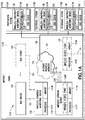
Fig. 1 is a block diagram of an apparatus for managing aircraft health data, according to one or more aspects of the present disclosure; -
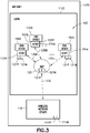
Fig. 2 is a schematic illustration of an apparatus for managing aircraft health data, according to one or more aspects of the present disclosure; -
Fig. 3 is a schematic illustration of an apparatus for managing aircraft health data, according to one or more aspects of the present disclosure; -
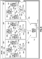
Fig. 4 is a schematic illustration of an apparatus for managing aircraft health data, according to one or more aspects of the present disclosure; -
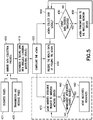
Fig. 5 is a flow diagram of a method, according to one or more aspects of the present disclosure; -
Fig. 6 is a block diagram of aircraft production and service methodology; and -
Fig. 7 is a schematic illustration of an aircraft. - In
Fig. 1 , referred to above, solid lines, if any, connecting various elements and/or components may represent mechanical, electrical, fluid, optical, electromagnetic, wireless and other couplings and/or combinations thereof. As used herein, "coupled" means associated directly as well as indirectly. For example, a member A may be directly associated with a member B, or may be indirectly associated therewith, e.g., via another member C. It will be understood that not all relationships among the various disclosed elements are necessarily represented. Accordingly, couplings other than those depicted in the block diagrams may also exist. Dashed lines, if any, connecting blocks designating the various elements and/or components represent couplings similar in function and purpose to those represented by solid lines; however, couplings represented by the dashed lines may either be selectively provided or may relate to alternative examples of the present disclosure. Likewise, elements and/or components, if any, represented with dashed lines, indicate alternative examples of the present disclosure. One or more elements shown in solid and/or dashed lines may be omitted from a particular example without departing from the scope of the present disclosure. Environmental elements, if any, are represented with dotted lines. Virtual (imaginary) elements may also be shown for clarity. Those skilled in the art will appreciate that some of the features illustrated inFig. 1 , may be combined in various ways without the need to include other features described inFig. 1 , other drawing figures, and/or the accompanying disclosure, even though such combination or combinations are not explicitly illustrated herein. Similarly, additional features not limited to the examples presented, may be combined with some or all of the features shown and described herein. - In
Figs. 5 and6 , referred to above, the blocks may represent operations and/or portions thereof and lines connecting the various blocks do not imply any particular order or dependency of the operations or portions thereof. Blocks represented by dashed lines indicate alternative operations and/or portions thereof. Dashed lines, if any, connecting the various blocks represent alternative dependencies of the operations or portions thereof. It will be understood that not all dependencies among the various disclosed operations are necessarily represented.Figs. 5 and6 and the accompanying disclosure describing the operations of the method(s) set forth herein should not be interpreted as necessarily determining a sequence in which the operations are to be performed. Rather, although one illustrative order is indicated, it is to be understood that the sequence of the operations may be modified when appropriate. Accordingly, certain operations may be performed in a different order or simultaneously. Additionally, those skilled in the art will appreciate that not all operations described need be performed. - In the following description, numerous specific details are set forth to provide a thorough understanding of the disclosed concepts, which may be practiced without some or all of these particulars. In other instances, details of known devices and/or processes have been omitted to avoid unnecessarily obscuring the disclosure. While some concepts will be described in conjunction with specific examples, it will be understood that these examples are not intended to be limiting.
- Unless otherwise indicated, the terms "first," "second," etc. are used herein merely as labels, and are not intended to impose ordinal, positional, or hierarchical requirements on the items to which these terms refer. Moreover, reference to, e.g., a "second" item does not require or preclude the existence of, e.g., a "first" or lower-numbered item, and/or, e.g., a "third" or higher-numbered item.
- Reference herein to "one example" means that one or more feature, structure, or characteristic described in connection with the example is included in at least one implementation. The phrase "one example" in various places in the specification may or may not be referring to the same example.
- As used herein, a system, apparatus, structure, article, element, component, or hardware "configured to" perform a specified function is indeed capable of performing the specified function without any alteration, rather than merely having potential to perform the specified function after further modification. In other words, the system, apparatus, structure, article, element, component, or hardware "configured to" perform a specified function is specifically selected, created, implemented, utilized, programmed, and/or designed for the purpose of performing the specified function. As used herein, "configured to" denotes existing characteristics of a system, apparatus, structure, article, element, component, or hardware which enable the system, apparatus, structure, article, element, component, or hardware to perform the specified function without further modification. For purposes of this disclosure, a system, apparatus, structure, article, element, component, or hardware described as being "configured to" perform a particular function may additionally or alternatively be described as being "adapted to" and/or as being "operative to" perform that function.
- Illustrative, non-exhaustive examples, which may or may not be claimed, of the subject matter according the present disclosure are provided below.
- Referring to
Fig. 1 an apparatus for managing aircraft health data 100 (referred to herein as the "apparatus 100") is illustrated. Theapparatus 100 provides for wireless monitoring of aircraft equipment where data collected from the aircraft equipment is used for health management of the aircraft equipment to support fault diagnostics and prognostics. In one aspect, the aircraft equipment is aircraft cabin equipment while in other aspects, the aircraft equipment isflight deck 1140 equipment,aircraft control surfaces 1150,aircraft landing gear 1160 and/or any other equipment onboard the aircraft that may be part of theaircraft propulsion system 1124,electrical system 1126,hydraulic system 1128 and/orenvironmental system 1130. As will be described in greater detail herein, theapparatus 100 utilizes an aircraftwireless network 125, such as an aircraft cabin wireless network, already onboard the aircraft which reduces wiring effort for theapparatus 100, reduces the weight of the aircraft and reduces the cost of the aircraft (e.g. due to a decreased use of wires). The data management of theapparatus 100 over the aircraftwireless network 125 is efficient and reduces network congestion and power consumed by wirelesscondition monitoring devices 130 of theapparatus 100 and/orend devices 150 to which the wirelesscondition monitoring devices 130 are coupled to or are a part of. As described herein, in one aspect, theapparatus 100 is configured to divide the data obtained from theend devices 150 into both event driven and polled messages for an efficient use of existing wireless spectrum resources on the aircraft (e.g. a mobile platform) and reduces contention to the wireless spectrum resources. In addition, the limited transmissions made by theapparatus 100, e.g. due to at least the event driven and polled message scheme, the power sources of the wirelesscondition monitoring devices 130 may be made smaller which reduces the size of the wirelesscondition monitoring devices 130 so that the wirelesscondition monitoring devices 130 fit into an existing envelope of (e.g. the allotted space for) theend device 150 being monitored. Further, because theapparatus 100 uses the existing aircraftwireless network 125, theapparatus 100 may be installed in any newly manufactured aircraft as well as retrofit into any existing aircraft including but not limited to variants of the Boeing 777. In the event the aircraft does not have an aircraft wireless network one may be installed in the aircraft in conjunction with installing theapparatus 100. Theapparatus 100 may prevent theend devices 150, of the aircraft, being monitored from entering a fault mode during flights, as the data collected from theend devices 150 by theapparatus 100 may detect possible faults prior to the occurrence of the fault so that theend device 150 may be repaired or replaced prior to any (subsequent) flight of the aircraft. - The
apparatus 100 includes awireless network server 110 disposed onboard anaircraft 1102 and at least one wireless condition monitoring device 130 (also referred to herein as "wCMD") disposed within at least acabin 1122 of theaircraft 1102. In other aspects, the at least one wirelesscondition monitoring device 130 may be located outside thecabin 1122, such as on theflight deck 1140 of theaircraft 1102, in the fuselage adjacent an outer surface (e.g. control surface 1150) of theaircraft 1102, on thelanding gear 1160 of theaircraft 1102 or at any other location of theaircraft 1102. The at least one wirelesscondition monitoring device 130 is wirelessly connected to thewireless network server 110 and is configured to transmit respective health data to thewireless network server 110 based on a communication scheme that maintains an availability of theaircraft wireless network 125, where theaircraft wireless network 125 is an aircraft information network not available for passenger/public use. Thewireless network server 110 may be an airplane information server or part of a controller onboard anaircraft 1102. In one aspect, thewireless network server 110 is located within the interior orcabin 1122 of theaircraft 1102 while in other aspects, thewireless network server 110 may be located at any suitable location onboard theaircraft 1102. Thewireless network server 110 includes aprocessor 111P and amemory 111M that are configured with, e.g., suitable programming to execute the aspects of the present disclosure described herein. Thewireless network server 110 communicates with the at least one wirelesscondition monitoring device 130 in any suitable manner such as through a direct connection or an indirect connection and using any suitable wireless communication protocol. For example, in one aspect, thewireless network server 110 communicates substantially directly with at least one wireless condition monitoring device over awireless connection 135; while in other aspects, the connection between thewireless network server 110 and the at least one wirelesscondition monitoring device 130 is an indirect connection through one or more wireless access points 120. Eachwireless access point 120 includes aprocessor 121P and amemory 121M that are configured with, e.g., suitable programming to execute the aspects of the present disclosure described herein. Thewireless access point 120 communicates with respective wirelesscondition monitoring devices 130 through, for example,wireless connection 135 using any suitable wireless communication protocol and communicates with the wireless network server throughconnection 136, where theconnection 136 is, in one aspect, a wireless connection using any suitable wireless communication protocol and in other aspects theconnection 136 is a wired connection. - Each wireless
condition monitoring device 130 includes aprocessor 131P and amemory 131M that are configured with, e.g., suitable programming to execute the aspects of the present disclosure described herein. In one aspect, each wirelesscondition monitoring device 130 is coupled to one ormore end devices 150 byconnection 151 in any suitable manner, where theconnection 151 is a wireless or a wired connection. In another aspect, a wirelesscondition monitoring device 130 may be integrated within the device being monitored. One ormore end devices 150 may be any suitable device(s) within thecabin 1122 of theaircraft 1102 including, but not limited to, for example, aircraft passenger seating monitoring device for monitoring actuation system(s) of one or more respective seats, passenger seat actuator(s), aircraft lavatory equipment monitoring device(s) for monitoring operation of lavatory equipment, lavatory equipment (fluid pumps, lighting, ventilation fans, etc.), cabin lighting, aircraft service galley equipment monitoring device(s) for monitoring one or more devices of a respective galley, service galley equipment (e.g. microwaves, refrigerators, lighting, etc.), cabin information displays (e.g. no smoking displays, exit sign displays, fasten seatbelt displays, etc.), aircraft cabin video and audio monitoring device(s) for monitoring operation of one or more aircraft passenger entertainment devices, aircraft video entertainment displays (such as seat back mounted or cabin mounted video displays), aircraft audio entertainment equipment and aircraft power outlets (e.g. USB or alternating current power outlets). In other aspects, theend devices 150 may be any suitable devices exterior to thecabin 1122 of theaircraft 1102 such as flight control equipment on theflight deck 1140, actuators forcontrol surfaces 1150 of theaircraft 1102, actuators of thelanding gear 1160 of theaircraft 1102 or any other suitable components of the propulsion, electrical, hydraulic and/orenvironmental systems aircraft 1102. - Referring to
Figs. 2-4 , in one aspect, the wirelesscondition monitoring devices 130A-130n will be described with respect to theaircraft cabin 1122 however wireless network configurations that have configurations corresponding to those described herein for theaircraft cabin 1122 are applied when theapparatus 100 includes wireless condition monitoring devices for monitoring end devices 150 (such as those described above) located outside thecabin 1122. Referring toFig. 2 , theapparatus 100 includes any suitable number of wirelesscondition monitoring devices 130A-130n disposed within thecabin 1122 where each wirelesscondition monitoring device 130A-130n is coupled to arespective end device 150A-150n that is also disposed within thecabin 1122, again noting that in other aspects, the end devices and wireless condition monitoring devices may also be located outside thecabin 1122. In other aspects, at least one wirelesscondition monitoring device 130A-130n may be coupled to more than oneend device 150A-150n for collecting data from the more than oneend device 150A-150n. In this aspect, each wirelesscondition monitoring device 130A-130n is substantially directly wirelessly connected to thewireless network server 110. Also in this aspect, thewireless network server 110 integrally includes the wireless access point 110AP for wirelessly communicating with the wirelesscondition monitoring devices 130A-130n although in other aspects, similar to that described below, a separate wireless access point may be used. In one aspect, thewireless network server 110 manages each of the wirelesscondition monitoring devices 130A-130n in terms of configuration control, security, business logic and prioritization of messages being transmitted over theaircraft wireless network 125 as described herein. - Referring to
Fig. 3 , in one aspect, theapparatus 100 includes any suitable number of wirelesscondition monitoring devices 130A-130n disposed within thecabin 1122 where each wirelesscondition monitoring device 130A-130n is coupled to arespective end device 150A-150n that is also disposed within thecabin 1122, again noting that in other aspects, the end devices and wireless condition monitoring devices may also be located outside thecabin 1122. In other aspects, at least one wirelesscondition monitoring device 130A-130n may be coupled to more than oneend device 150A-150n for collecting data from the more than oneend device 150A-150n. In this aspect, each wirelesscondition monitoring device 130A-130n is wirelessly connected towireless access point 120. Thewireless access point 120 is, in one aspect, also disposed within thecabin 1122 while in other aspects, thewireless access point 120 may be disposed at any suitable location onboard theaircraft 1102. In this aspect, thewireless access point 120 is connected to thewireless network server 110 overwireless connection 136 while in other aspects, the connection between thewireless access point 120 and the wireless network server may be a wired connection. In one aspect, thewireless network server 110 manages each of the wirelesscondition monitoring devices 130A-130n as well as thewireless access point 120 in terms of configuration control, security, business logic and prioritization of messages being transmitted over theaircraft wireless network 125 as described herein. - Referring to
Fig. 4 , in one aspect, the wirelesscondition monitoring devices 130A-130n are divided intoequipment groups 140A-140n. Eachequipment group 140A-140n includes a respectivewireless access point 120A-120n and a respective one or more wirelesscondition monitoring device 130A-130n. Each of the wirelesscondition monitoring devices 130A-130n for arespective group 140A-140n is in wireless communication with thewireless access point 120A-120n for thatgroup 140A-140n in the manner described above. Each of thewireless access points 120A-120n is wirelessly connected (or in other aspects connected by wire) to thewireless network server 110 in the manner described above. In one aspect, thewireless network server 110 manages the components of each of theequipment groups 140A-140n in terms of configuration control, security, business logic and prioritization of messages being transmitted over theaircraft wireless network 125 as described herein. - Referring to
Fig. 2 , in one aspect, where more than one wirelesscondition monitoring devices condition monitoring devices apparatus 100. In other aspects, the wirelesscondition monitoring devices condition monitoring devices condition monitoring devices condition monitoring device condition monitoring device Figs. 2 and3 and/or inmultiple equipment groups 140A-140n as illustrated inFig. 4 ). In one aspect, the master wirelesscondition monitoring device condition monitoring devices wireless network server 110. In other aspects, the master wirelesscondition monitoring device condition monitoring devices aircraft wireless network 125 is substantially free from interference). - In one aspect, the wireless communication between the wireless
condition monitoring devices wireless network server 110 within theaircraft wireless network 125 is performed over a secure wireless connection. Likewise, when thewireless access point condition monitoring devices wireless access point wireless access point wireless network server 110 is performed over a secure wireless connection. The secure connections between the wirelessconditioning monitoring devices wireless network server 110 may be established in any suitable manner including registration of a MAC address and/or a unique identifier of each of the wirelessconditioning monitoring devices wireless network server 110, that is stored as persistent configuration data of the aircraft. In one aspect, the unique identifier may be a respective serial number of the wirelessconditioning monitoring device conditioning monitoring devices wireless access point conditioning monitoring device wireless access point wireless access point wireless network server 110 may be established in any suitable manner including registration of a MAC address and/or unique identifier of thewireless access point wireless network server 110. In one aspect, thewireless network server 110 may include a registry of the MAC addresses and/or unique identifier(s) of the wireless condition monitoring device(s) 130, 130A-130n. In another aspect, where one or morewireless access points wireless network server 110 may include a registry of the MAC addresses and/or unique identifiers of both the wireless condition monitoring device(s) 130, 130A-130n and the wireless access point(s) 120, 120A-120n and/or a registry correlating the wireless condition monitoring device(s) 130, 130A-130n with the respective wireless access point(s) 120, 120A-120n. In one aspect, the wirelesscondition monitoring devices wireless access points apparatus 100 only if the respective wirelesscondition monitoring device wireless access point wireless network server 110 however, in other aspects the MAC addresses and/or unique identifiers may be sent at any suitable times. Sending a MAC address and/or unique identifier only when the associated device (e.g. wireless condition monitoring device or wireless access point) is not already registered with thewireless network server 110 reducesapparatus 100 network traffic within theaircraft wireless network 125 providing for a more secure wireless link to be established. In one aspect, the MAC addresses and/or unique identifiers of the wirelesscondition monitoring devices wireless access points condition monitoring devices wireless access points condition monitoring devices wireless access points aircraft wireless network 125 for communicating with thewireless network server 110 is restricted to authorized wirelesscondition monitoring devices wireless network server 110 is configured to reject any unauthorized device attempting to access the aircraft wireless network 125). Devices from other aircraft parked alongsideaircraft 1102, such as at an airport gate, are also prevented from accessing theaircraft wireless network 125, thewireless network server 110, the wirelesscondition monitoring devices wireless access points wireless network server 110, the wirelesscondition monitoring devices wireless access points wireless network server 110, the wirelesscondition monitoring devices wireless access points aircraft 1102. - As noted above, communication between the wireless
condition monitoring devices network server 110 is performed in accordance with a predetermined communication scheme. In one aspect, the predetermined communication scheme is a prioritized communication scheme where communications are prioritized based on event prioritization where an event requiring higher precedence will be transmitted before events having a lower priority. In one aspect, the prioritized communication includes one or more of spatial logic (e.g. spatial locations of the devices) and temporal logic. In one aspect, spatial and temporal logic are mixed in the communication scheme to increase security of the network by increasing the complexity of communication timing (e.g. a regular communication pattern may not be readily discernable) within the communication scheme. In one aspect, the at least one wirelesscondition monitoring device wireless network server 110 based on an occurrence of a predetermined event, such as aircraft take-off, aircraft landing, in-flight, etc. In one aspect,end devices condition monitoring devices priority end devices aircraft wireless network 125 before wirelesscondition monitoring devices priority end devices - In one aspect, the
wireless network server 110 is configured to poll at least one wirelesscondition monitoring device condition monitoring device wireless network server 110 is configured for both polling and event-driven messaging with the at least one wirelesscondition monitoring device wireless network server 110 may be controlled so that the wirelesscondition monitoring devices priority end devices condition monitoring devices priority end devices - In one aspect, at least one wireless
condition monitoring device condition monitoring device wireless network server 110 where urgent health data messages are transferred at any suitable time and lower priority health data messages are transmitted when polled by thewireless network server 110 depending on, for example, the context (e.g. take-off, in-flight or landing phases of flight) of the health data. In one aspect, each wirelesscondition monitoring device condition monitoring device - In one aspect, the
apparatus 100 employs context (e.g. take-off, in-flight or landing phases of flight) aware data management that uses predefined rules to perform data logging. In one aspect, the at least one wirelesscondition monitoring device memory 111M of thewireless network server 110, where the business rules relate to time sensitivity of the health data and a context of the health data. In one aspect, the business rules may specify that health data collected for a given flight phase is transferred to and stored by thewireless network server 110 prior to a next flight phase (e.g. data collected during flight is transferred and stored in the wireless network server prior to the landing flight phase). In other aspects, the health data collected by the wirelesscondition monitoring devices wireless network server 110 at any suitable times during flight. In one aspect, each wirelesscondition monitoring device condition monitoring devices end device condition monitoring devices - In one aspect, one or more of the
wireless network server 110, thewireless access points condition monitoring devices aircraft wireless network 125. For example, in one aspect, each of the at least one wireless condition monitoring device is configured to monitor theaircraft wireless network 125 for interference and locally store health data collected by the at least one wirelesscondition monitoring device memory 131M of the at least one wirelesscondition monitoring device condition monitoring device aircraft wireless network 125 for interference, such as at predetermined time intervals so decrease power usage, and transmit the stored health data to thewireless network server 110 when the interference clears. Similarly, eachwireless access point aircraft wireless network 125 for interference and locally store health data received from the respective wireless condition monitoring device(s) 130, 130A-130n in thememory 121M of thewireless access point wireless access point aircraft wireless network 125 for interference, such as at predetermined time intervals, and transmit the stored health data to thewireless network server 110 when the interference clears. Thewireless network server 110 may also be configured to monitor theaircraft wireless network 125 for interference, such as at predetermined time intervals and/or prior to/coincident with a polling message, and poll the wirelesscondition monitoring devices - In one aspect, as described herein, the
apparatus 100 supports health data monitoring that is event driven, poll driven or both event driven and poll driven. For example, data sets for theend device end device condition monitoring device memory 131M for therespective end device wireless network server 110. In one aspect, polling by thewireless network server 110 may occur at any predetermined time interval such as for example, between about two (2) minutes and about fifty (50) minutes while in other aspects the polling intervals may be less than about two minutes and more than about fifty minutes. In the event that the stored list of health data exceeds a predetermined threshold (e.g. the stored data exceeds a predetermined amount of storage, is locally stored for a predetermined amount of time, etc.), the at least one wirelesscondition monitoring device wireless network server 110 to do so. The event driven and polled messaging described herein reduces power consumption by the at least one wirelesscondition monitoring device apparatus 100 over theaircraft wireless network 125 so as to reduce overall traffic on theaircraft wireless network 125. - Referring now to
Fig. 5 and also toFigs. 1-4 , an exemplary operation of theapparatus 100 will be described in accordance with the present disclosure. In one aspect, the data collection process is initiated (Fig. 5 , Block 400), such as before a flight of the aircraft, where business rules 401, such as those described above for event driven data, are programmed into thewireless network server 110. Transmission rate and message aggregation rules andcontext 402, such as those described above for poll driven data, may also be programmed into thewireless network server 110. A secure link is established between thewireless network server 110 and the wirelesscondition monitoring devices Fig. 5 , Block 410) in the manner described above, where for example, MAC addresses and/or unique identifiers of the wirelesscondition monitoring devices wireless network server 110. The establishment of the secure network communication(s) provides for authentication and authorization to ensure only valid/authorized wirelesscondition monitoring devices aircraft wireless network 125. Configuration messages are sent from thewireless network server 110 to the wirelesscondition monitoring devices rules condition monitoring devices Fig. 5 , Block 420). For example, in one aspect, the configuration messages include information that assigns a priority to the end device(s) coupled to each wirelesscondition monitoring devices condition monitoring devices condition monitoring devices condition monitoring devices - In one aspect, the wireless
condition monitoring devices Fig. 5 , Block 470). In one aspect, the wireless network resource request occurs prior to flight of the aircraft and after/during configuration of the wirelesscondition monitoring devices condition monitoring devices condition monitoring devices condition monitoring devices Fig. 5 , Block 480). Where the wireless network resource request is denied a resource denial message is sent to the wirelesscondition monitoring devices condition monitoring devices condition monitoring devices condition monitoring devices Fig. 5 , Block 490) for communicating over theaircraft wireless network 125. In one aspect, the network resources allocated by the wirelesscondition monitoring devices - The wireless
condition monitoring devices Fig. 5 , Block 440). As described above, the health data collected by the wirelesscondition monitoring devices wireless network server 110 based on polling or events. In one aspect, the health data is received from the wirelesscondition monitoring devices condition monitoring devices Fig. 5 , Block 430). The wirelesscondition monitoring devices condition monitoring devices Fig. 5 , Block 450). Where the event exceeds the threshold, the wirelesscondition monitoring devices Fig. 5 , Block 460). Where the event does not exceed the threshold, the wirelesscondition monitoring devices wireless network server 110. - Examples of the present disclosure may be described in the context of aircraft manufacturing and
service method 1100 as shown inFig. 6 andaircraft 1102 as shown inFig. 7 . During pre-production,illustrative method 1100 may include specification and design (block 1104) ofaircraft 1102 and material procurement (block 1106). During production, component and subassembly manufacturing (block 1108) and system integration (block 1110) ofaircraft 1102 may take place. Thereafter,aircraft 1102 may go through certification and delivery (block 1112) to be placed in service (block 1114). While in service,aircraft 1102 may be scheduled for routine maintenance and service (block 1116). Routine maintenance and service may include modification, reconfiguration, refurbishment, etc. of one or more systems ofaircraft 1102. - Each of the processes of
illustrative method 1100 may be performed or carried out by a system integrator, a third party, and/or an operator (e.g., a customer). For the purposes of this description, a system integrator may include, without limitation, any number of aircraft manufacturers and major-system subcontractors; a third party may include, without limitation, any number of vendors, subcontractors, and suppliers; and an operator may be an airline, leasing company, military entity, service organization, and so on. - As shown in
Fig. 7 ,aircraft 1102 produced byillustrative method 1100 may includeairframe 1118 with a plurality of high-level systems 1120 and interior orcabin 1122. Examples of high-level systems 1120 include one or more ofpropulsion system 1124,electrical system 1126,hydraulic system 1128, andenvironmental system 1130. Any number of other systems may be included. Although an aerospace example is shown, the principles disclosed herein may be applied to other industries, such as the automotive industry. Accordingly, in addition toaircraft 1102, the principles disclosed herein may apply to other vehicles that include wireless networks, e.g., land vehicles, marine vehicles, space vehicles, etc. - Apparatus(es) and method(s) shown or described herein may be employed during any one or more of the stages of the manufacturing and
service method 1100. For example, components or subassemblies corresponding to component and subassembly manufacturing (block 1108) may be fabricated or manufactured in a manner similar to components or subassemblies produced whileaircraft 1102 is in service (block 1114). Also, one or more examples of the apparatus(es), method(s), or combination thereof may be utilized duringproduction stages aircraft 1102. Similarly, one or more examples of the apparatus or method realizations, or a combination thereof, may be utilized, for example and without limitation, whileaircraft 1102 is in service (block 1114) and/or during maintenance and service (block 1116). - A. In accordance with one or more aspects of the present disclosure, an apparatus for managing aircraft health data comprises:
- a wireless network server disposed onboard an aircraft;
- at least one wireless condition monitoring device disposed at least within a cabin of the aircraft, wirelessly connected to the wireless network server and configured to transmit respective health data to the wireless network server based on a communication scheme that maintains an availability of an aircraft wireless network.
- A1. The apparatus of paragraph A, wherein the wireless connection between the wireless network server and the at least one wireless condition monitoring device is a secure connection.
- A2. The apparatus of paragraph A1, wherein the secure connection includes registration of a MAC address or a unique identifier of the at least one wireless conditioning monitoring device with the wireless network server.
- A3. The apparatus of paragraph A, wherein the communication scheme is a prioritized communication scheme that includes one or more of spatial logic and temporal logic.
- A4. The apparatus of paragraph A, wherein the wireless network server is configured to poll the at least one wireless condition monitoring device at predetermined time intervals for the transmission of health data from the at least one wireless condition monitoring device.
- A5. The apparatus of paragraph A, wherein the at least one wireless condition monitoring device is configured to transmit health data to the wireless network server based on an occurrence of a predetermined event.
- A6. The apparatus of paragraph A, wherein the at least one wireless condition monitoring device is configured to prioritize health data prior to transmission of the health data to the wireless network server.
- A7. The apparatus of paragraph A, wherein the at least one wireless condition monitoring device is configured to:
- monitor the aircraft wireless network for interference and locally store health data collected by the at least one wireless condition monitoring device when interference is present; and
- transmit the stored health data to the wireless network server when the interference clears.
- A8. The apparatus of paragraph A, wherein the at least one wireless condition monitoring device is configured to record predetermined health data based on rules assigned to a corresponding flight for the aircraft where the predetermined health data is transmitted to and stored by the wireless server for onboard or off-board analysis.
- A9. The apparatus of paragraph A, wherein the at least one wireless condition monitoring device includes or is connected to one or more of:
- an aircraft seating monitoring device for monitoring actuation of one or more respective seats;
- an aircraft lavatory equipment monitoring device for monitoring operation of lavatory equipment;
- an aircraft cabin video and audio monitoring device for monitoring operation of one or more aircraft passenger entertainment devices;
- an aircraft service galley equipment monitoring device for monitoring one or more devices of a respective service galley;
- an aircraft flight deck equipment monitoring device for monitoring one or more devices of an aircraft flight deck;
- an aircraft control surface monitoring device for monitoring control surface actuators or movement of aircraft control surfaces; and
- an aircraft landing gear monitoring device for monitoring actuation or movement of aircraft landing gear.
- A10. The apparatus of paragraph A, wherein the at least one wireless condition monitoring device is configured to:
- send a resource request to the wireless network server; and
- allocate wireless network resources of the at least one wireless condition monitoring device depending on a receipt of a resource grant by the at least one wireless condition monitoring device from the wireless network server.
- A11. The apparatus of paragraph A10, wherein the wireless network resources include at least power and frequency requirements.
- A12. The apparatus of paragraph A, further comprising a wireless access point that wirelessly connects the at least one wireless condition monitoring device to the wireless network server.
- A13. The apparatus of paragraph A, further comprising more than one equipment group, each equipment group having at least one respective wireless condition monitoring device where the at least one respective wireless condition monitoring device of each equipment group is wirelessly connected to the wireless network receiver.
- A14. The apparatus of paragraph A13, wherein each equipment group includes a respective wireless access point, the respective wireless access point wirelessly connecting the at least one respective wireless condition monitoring device to the wireless network server.
- A15. The apparatus of paragraph A, wherein the at least one wireless condition monitoring device includes a master wireless condition monitoring device in communication with another wireless condition monitoring device of the at least one wireless condition monitoring device, the master wireless condition monitoring device being configured to communicate health data received from the other wireless condition monitoring device to the wireless network server.
- A16. The apparatus of paragraph A, wherein at least one of the at least one wireless condition monitoring devices is disposed within a cabin of the aircraft.
- A17. The apparatus of paragraph A, wherein the aircraft wireless network is an aircraft cabin wireless network.
- B. In accordance with one or more aspects of the present disclosure, a method for managing aircraft health data comprises:
- configuring communication between a wireless network server disposed onboard an aircraft and at least one wireless condition monitoring device disposed onboard the aircraft; and
- wirelessly transmitting respective health data from the at least one wireless condition monitoring device to the wireless network server based on a communication scheme that maintains an availability of an aircraft wireless network.
- B1. The method of paragraph B, wherein configuring communication between the wireless network server and the at least one wireless condition monitoring device includes establishing a secure connection.
- B2. The method of paragraph B1, wherein the establishing the secure connection includes registering a MAC address or a unique identifier of the at least one wireless conditioning monitoring device with the wireless network server.
- B3. The method of paragraph B, wherein the communication scheme is a prioritized communication scheme that includes one or more of spatial logic and temporal logic.
- B4. The method of paragraph B, further comprising polling the at least one wireless condition monitoring device, with the wireless network server, at predetermined time intervals and transmitting health data from the at least one wireless condition monitoring device to the wireless network server in response to the polling.
- B5. The method of paragraph B, further comprising transmitting to the wireless network server, from the at least one wireless condition monitoring device, health data based on an occurrence of a predetermined event.
- B6. The method of paragraph B, further comprising prioritizing health with the at least one wireless condition monitoring device prior to transmission of the health data to the wireless network server.
- B7. The method of paragraph B, further comprising:
- monitoring the aircraft wireless network, with the at least one wireless condition monitoring device, for interference and locally storing health data collected by the at least one wireless condition monitoring device when interference is present; and
- transmitting the stored health data to the wireless network server, from the at least one wireless condition monitoring device, when the interference clears.
- B8. The method of paragraph B, further comprising recording predetermined health data, with the at least one wireless condition monitoring device, based on rules assigned to a corresponding flight for the aircraft where the predetermined health data is transmitted to and stored by the wireless server for onboard or off-board analysis.
- B9. The method of paragraph B, wherein configuring communication between the wireless network server and the at least one wireless condition monitoring device includes:
- sending a resource request from the at least one wireless condition monitoring device to the wireless network server; and
- allocating wireless network resources with the at least one wireless condition monitoring device depending on a receipt of a resource grant by the at least one wireless condition monitoring device from the wireless network server.
- B10. The method of paragraph B9, wherein the wireless network resources include at least power and frequency requirements.
- B11. The method of paragraph B, wherein at least one of the at least one wireless condition monitoring devices is disposed within a cabin of the aircraft.
- B12. The apparatus of paragraph B, wherein the aircraft wireless network is an aircraft cabin wireless network.
- C. In accordance with one or more aspects of the present disclosure, an aircraft comprises:
- a cabin;
- at least one end device disposed onboard the aircraft; and
- an aircraft health data monitoring system that includes:
- a wireless network server disposed onboard the aircraft; and
- at least one wireless condition monitoring device associated with a respective one of the at least one end device and disposed onboard the aircraft, the at least one wireless condition monitoring device being wirelessly connected to the wireless network server and configured to transmit respective health data, corresponding to respective one of the at least one end device, to the network server based on a communication scheme that maintains an availability of an aircraft wireless network.
- C1. The aircraft of paragraph C, wherein the wireless connection between the wireless network server and the at least one wireless condition monitoring device is a secure connection.
- C2. The aircraft of paragraph C1, wherein the secure connection includes registration of a MAC address or a unique identifier of the at least one wireless conditioning monitoring device with the wireless network server.
- C3. The aircraft of paragraph C, wherein the communication scheme is a prioritized communication scheme that includes one or more of spatial logic and temporal logic.
- C4. The aircraft of paragraph C, wherein the wireless network server is configured to poll the at least one wireless condition monitoring device at predetermined time intervals for the transmission of health data from the at least one wireless condition monitoring device.
- C5. The aircraft of paragraph C, wherein the at least one wireless condition monitoring device is configured to transmit health data to the wireless network server based on an occurrence of a predetermined event.
- C6. The aircraft of paragraph C, wherein the at least one wireless condition monitoring device is configured to prioritize health data prior to transmission of the health data to the wireless network server.
- C7. The aircraft of paragraph C, wherein the at least one wireless condition monitoring device is configured to:
- monitor the aircraft wireless network for interference and locally store health data collected by the at least one wireless condition monitoring device when interference is present; and
- transmit the stored health data to the wireless network server when the interference clears.
- C8. The aircraft of paragraph C, wherein the at least one wireless condition monitoring device is configured to record predetermined health data based on rules assigned to a corresponding flight for the aircraft where the predetermined health data is transmitted to and stored by the wireless server for onboard or off-board analysis.
- C9. The aircraft of paragraph C, wherein the at least one wireless condition monitoring device includes or is connected to one or more of:
- an aircraft seating monitoring device for monitoring actuation of one or more respective seats;
- an aircraft lavatory equipment monitoring device for monitoring operation of lavatory equipment;
- an aircraft cabin video and audio monitoring device for monitoring operation of one or more aircraft passenger entertainment devices;
- an aircraft service galley equipment monitoring device for monitoring one or more devices of a respective service galley;
- an aircraft flight deck equipment monitoring device for monitoring one or more devices of an aircraft flight deck;
- an aircraft control surface monitoring device for monitoring control surface actuators or movement of aircraft control surfaces; and
- an aircraft landing gear monitoring device for monitoring actuation or movement of aircraft landing gear.
- C10. The aircraft of paragraph C, wherein the at least one wireless condition monitoring device is configured to:
- send a resource request to the wireless network server; and
- allocate wireless network resources of the at least one wireless condition monitoring device depending on a receipt of a resource grant by the at least one wireless condition monitoring device from the wireless network server.
- C11. The aircraft of paragraph C10, wherein the wireless network resources include at least power and frequency requirements.
- C12. The aircraft of paragraph C, further comprising a wireless access point that wirelessly connects the at least one wireless condition monitoring device to the wireless network server.
- C13. The aircraft of paragraph C, further comprising more than one equipment group, each equipment group having at least one respective wireless condition monitoring device where the at least one respective wireless condition monitoring device of each equipment group is wirelessly connected to the wireless network receiver.
- C14. The aircraft of paragraph C13, wherein each equipment group includes a respective wireless access point, the respective wireless access point wirelessly connecting the at least one respective wireless condition monitoring device to the wireless network server.
- C15. The aircraft of paragraph C, wherein the at least one wireless condition monitoring device includes a master wireless condition monitoring device in communication with another wireless condition monitoring device of the at least one wireless condition monitoring device, the master wireless condition monitoring device being configured to communicate health data received from the other wireless condition monitoring device to the wireless network server.
- C16. The aircraft of paragraph C, wherein at least one of the at least one wireless condition monitoring devices and at least one of the at least one device is disposed within a cabin of the aircraft.
- C17. The aircraft of paragraph C, wherein the aircraft wireless network is an aircraft cabin wireless network.
- Different examples of the apparatus(es) and method(s) disclosed herein include a variety of components, features, and functionalities. It should be understood that the various examples of the apparatus(es) and method(s) disclosed herein may include any of the components, features, and functionalities of any of the other examples of the apparatus(es) and method(s) disclosed herein in any combination, and all of such possibilities are intended to be within the scope of the present disclosure.
- Further, the disclosure comprises embodiments according to the following clauses:
- Clause 1. An apparatus for managing aircraft health data comprising:
- a wireless network server disposed onboard an aircraft;
- at least one wireless condition monitoring device disposed onboard the aircraft, wirelessly connected to the wireless network server and configured to transmit respective health data to the wireless network server based on a communication scheme that maintains an availability of an aircraft wireless network.
- Clause 2. The apparatus of Clause 1, wherein the communication scheme is a prioritized communication scheme that includes one or more of spatial logic and temporal logic.
- Clause 3. The apparatus of Clauses 1 or 2, wherein the wireless network server is configured to poll the at least one wireless condition monitoring device at predetermined time intervals for the transmission of health data from the at least one wireless condition monitoring device.
- Clause 4. The apparatus of Clauses 1, 2 or 3, wherein the at least one wireless condition monitoring device is configured to transmit health data to the wireless network server based on an occurrence of a predetermined event.
- Clause 5. The apparatus of Clauses 1, 2, 3 or 4, wherein the at least one wireless condition monitoring device is configured to prioritize health data prior to transmission of the health data to the wireless network server.
- Clause 6. The apparatus of Clauses 1, 2, 3, 4 or 5, wherein the at least one wireless condition monitoring device is configured to:
- monitor the aircraft wireless network for interference and locally store health data collected by the at least one wireless condition monitoring device when interference is present; and
- transmit the stored health data to the wireless network server when the interference clears.
- Clause 7. The apparatus of Clauses 1, 2, 3, 4, 5 or 6, wherein the at least one wireless condition monitoring device is configured to:
- send a resource request to the wireless network server; and
- allocate wireless network resources of the at least one wireless condition monitoring device depending on a receipt of a resource grant by the at least one wireless condition monitoring device from the wireless network server.
- Clause 8. The apparatus of Clauses 1, 2, 3, 4, 5, 6 or 7, wherein the at least one wireless condition monitoring device includes or is connected to one or more of:
- an aircraft seating monitoring device for monitoring actuation of one or more respective seats;
- an aircraft lavatory equipment monitoring device for monitoring operation of lavatory equipment;
- an aircraft cabin video and audio monitoring device for monitoring operation of one or more aircraft passenger entertainment devices;
- an aircraft service galley equipment monitoring device for monitoring one or more devices of a respective service galley;
- an aircraft flight deck equipment monitoring device for monitoring one or more devices of an aircraft flight deck;
- an aircraft control surface monitoring device for monitoring control surface actuators or movement of aircraft control surfaces; and
- an aircraft landing gear monitoring device for monitoring actuation or movement of aircraft landing gear.
- Clause 9. The apparatus of Clauses 1, 2, 3, 4, 5, 6, 7 or 8, further comprising more than one equipment group, each equipment group having at least one respective wireless condition monitoring device where the at least one respective wireless condition monitoring device of each equipment group is wirelessly connected to the wireless network receiver.
- Clause 10. The apparatus of Clauses 1, 2, 3, 4, 5, 6, 7, 8 or 9, wherein the at least one wireless condition monitoring device includes a master wireless condition monitoring device in communication with another wireless condition monitoring device of the at least one wireless condition monitoring device, the master wireless condition monitoring device being configured to communicate health data received from the other wireless condition monitoring device to the wireless network server.
- Clause 11. The apparatus of Clauses 1, 2, 3, 4, 5, 6, 7, 8, 9 or 10, wherein at least one of the at least one wireless condition monitoring devices is disposed within a cabin of the aircraft.
- Clause 12. A method for managing aircraft health data comprising:
- configuring communication between a wireless network server disposed onboard an aircraft and at least one wireless condition monitoring device disposed onboard the aircraft; and
- wirelessly transmitting respective health data from the at least one wireless condition monitoring device to the wireless network server based on a communication scheme that maintains an availability of an aircraft wireless network.
- Clause 13. The method of Clause 12, wherein configuring communication between the wireless network server and the at least one wireless condition monitoring device includes establishing a secure connection.
- Clause 14. The method of Clauses 12 or 13, wherein the communication scheme is a prioritized communication scheme that includes one or more of spatial logic and temporal logic.
- Clause 15. The method of Clauses 12, 13 or 14, further comprising polling the at least one wireless condition monitoring device, with the wireless network server, at predetermined time intervals and transmitting health data from the at least one wireless condition monitoring device to the wireless network server in response to the polling.
- Clause 16. The method of Clauses 12, 13, 14 or 15, further comprising transmitting to the wireless network server, from the at least one wireless condition monitoring device, health data based on an occurrence of a predetermined event.
- Clause 17. The method of Clauses 12, 13, 14, 15 or 16, further comprising:
- monitoring the aircraft wireless network, with the at least one wireless condition monitoring device, for interference and locally storing health data collected by the at least one wireless condition monitoring device when interference is present; and
- transmitting the stored health data to the wireless network server, from the at least one wireless condition monitoring device, when the interference clears.
- Clause 18. The method of Clauses 12, 13, 14, 15, 16 or 17, wherein configuring communication between the wireless network server and the at least one wireless condition monitoring device includes:
- sending a resource request from the at least one wireless condition monitoring device to the wireless network server; and
- allocating wireless network resources with the at least one wireless condition monitoring device depending on a receipt of a resource grant by the at least one wireless condition monitoring device from the wireless network server.
- Clause 19. An aircraft comprising:
- a cabin;
- at least one end device disposed onboard the aircraft; and
- an aircraft health data monitoring system that includes:
- a wireless network server disposed onboard the aircraft; and
- at least one wireless condition monitoring device associated with a respective one of the at least one end device and disposed onboard the aircraft, the at least one wireless condition monitoring device being wirelessly connected to the wireless network server and configured to transmit respective health data, corresponding to respective one of the at least one end device, to the network server based on a communication scheme that maintains an availability of an aircraft wireless network.
- Clause 20. The aircraft of Clause 19, wherein the communication scheme is a prioritized communication scheme that includes one or more of spatial logic and temporal logic.
- Many modifications of examples set forth herein will come to mind to one skilled in the art to which the present disclosure pertains having the benefit of the teachings presented in the foregoing descriptions and the associated drawings.
- Therefore, it is to be understood that the present disclosure is not to be limited to the specific examples illustrated and that modifications and other examples are intended to be included within the scope of the appended claims. Moreover, although the foregoing description and the associated drawings describe examples of the present disclosure in the context of certain illustrative combinations of elements and/or functions, it should be appreciated that different combinations of elements and/or functions may be provided by alternative implementations without departing from the scope of the appended claims. Accordingly, parenthetical reference numerals in the appended claims are presented for illustrative purposes only and are not intended to limit the scope of the claimed subject matter to the specific examples provided in the present disclosure.
Claims (15)
- An apparatus for managing aircraft health data (100) comprising:a wireless network server (110) disposed onboard an aircraft (1102);at least one wireless condition monitoring device (130) disposed onboard the aircraft (1102), wirelessly connected to the wireless network server (110) and configured to transmit respective health data to the wireless network server (110) based on a communication scheme that maintains an availability of an aircraft wireless network (125).
- The apparatus (100) of claim 1, wherein the communication scheme is a prioritized communication scheme that includes one or more of spatial logic and temporal logic.
- The apparatus (100) of claims 1 or 2, wherein the wireless network server (110) is configured to poll the at least one wireless condition monitoring device (130) at predetermined time intervals for the transmission of health data from the at least one wireless condition monitoring device (130).
- The apparatus (100) of claims 1, 2 or 3, wherein the at least one wireless condition monitoring device (130) is configured to transmit health data to the wireless network server (110) based on an occurrence of a predetermined event.
- The apparatus (100) of claims 1, 2, 3 or 4, wherein the at least one wireless condition monitoring device (130) is configured to prioritize health data prior to transmission of the health data to the wireless network server (110).
- The apparatus (100) of claims 1, 2, 3, 4 or 5, wherein the at least one wireless condition monitoring device (130) is configured to:monitor the aircraft wireless network (125) for interference and locally store health data collected by the at least one wireless condition monitoring device (130) when interference is present; andtransmit the stored health data to the wireless network server (110) when the interference clears.
- The apparatus (100) of claims 1, 2, 3, 4, 5 or 6, wherein the at least one wireless condition monitoring device (130) is configured to:send a resource request to the wireless network server (110); andallocate wireless network resources of the at least one wireless condition monitoring device (130) depending on a receipt of a resource grant by the at least one wireless condition monitoring device (130) from the wireless network server (110).
- The apparatus (100) of claims 1, 2, 3, 4, 5, 6 or 7, wherein the at least one wireless condition monitoring device (130) includes or is connected to one or more of:an aircraft seating monitoring device for monitoring actuation of one or more respective seats;an aircraft lavatory equipment monitoring device for monitoring operation of lavatory equipment;an aircraft cabin video and audio monitoring device for monitoring operation of one or more aircraft passenger entertainment devices;an aircraft service galley equipment monitoring device for monitoring one or more devices of a respective service galley;an aircraft flight deck equipment monitoring device for monitoring one or more devices of an aircraft flight deck (1140);an aircraft control surface monitoring device for monitoring control surface actuators or movement of aircraft control surfaces (1150); andan aircraft landing gear monitoring device for monitoring actuation or movement of aircraft landing gear (1160).
- The apparatus (100) of claims 1, 2, 3, 4, 5, 6, 7 or 8, further comprising more than one equipment group (140A-140n), each equipment group having at least one respective wireless condition monitoring device (130) where the at least one respective wireless condition monitoring device (130) of each equipment group (140A-140n) is wirelessly connected to the wireless network receiver.
- The apparatus (100) of claims 1, 2, 3, 4, 5, 6, 7, 8 or 9, wherein the at least one wireless condition monitoring device (130) includes a master wireless condition monitoring device (130) in communication with another wireless condition monitoring device (130) of the at least one wireless condition monitoring device (130), the master wireless condition monitoring device being configured to communicate health data received from the other wireless condition monitoring device (130) to the wireless network server (110).
- A method for managing aircraft health data comprising:configuring communication between a wireless network server (110) disposed onboard an aircraft (1102) and at least one wireless condition monitoring device (130) disposed onboard the aircraft (1102); andwirelessly transmitting respective health data from the at least one wireless condition monitoring device (130) to the wireless network server (110) based on a communication scheme that maintains an availability of an aircraft wireless network (125).
- The method of claim 11, wherein the communication scheme is a prioritized communication scheme that includes one or more of spatial logic and temporal logic.
- The method of claims 11 or 12, further comprising polling the at least one wireless condition monitoring device (130), with the wireless network server (110), at predetermined time intervals and transmitting health data from the at least one wireless condition monitoring device (130) to the wireless network server (110) in response to the polling.
- The method of claims 11, 12 or 13, further comprising transmitting to the wireless network server (110), from the at least one wireless condition monitoring device (130), health data based on an occurrence of a predetermined event.
- The method of claims 11, 12, 13 or 14 further comprising:monitoring the aircraft wireless network (125), with the at least one wireless condition monitoring device (130), for interference and locally storing health data collected by the at least one wireless condition monitoring device (130) when interference is present; andtransmitting the stored health data to the wireless network server (110), from the at least one wireless condition monitoring device (130), when the interference clears.
Applications Claiming Priority (1)
| Application Number | Priority Date | Filing Date | Title |
|---|---|---|---|
| US15/165,225 US9926086B2 (en) | 2016-05-26 | 2016-05-26 | Apparatus and method for wirelessly managing aircraft health data |
Publications (2)
| Publication Number | Publication Date |
|---|---|
| EP3249942A1 true EP3249942A1 (en) | 2017-11-29 |
| EP3249942B1 EP3249942B1 (en) | 2022-03-02 |
Family
ID=58992609
Family Applications (1)
| Application Number | Title | Priority Date | Filing Date |
|---|---|---|---|
| EP17170251.7A Active EP3249942B1 (en) | 2016-05-26 | 2017-05-09 | Apparatus and method for wirelessly managing aircraft health data |
Country Status (4)
| Country | Link |
|---|---|
| US (1) | US9926086B2 (en) |
| EP (1) | EP3249942B1 (en) |
| JP (1) | JP6928480B2 (en) |
| CN (1) | CN107437279B (en) |
Cited By (2)
| Publication number | Priority date | Publication date | Assignee | Title |
|---|---|---|---|---|
| EP3588802A1 (en) * | 2018-06-28 | 2020-01-01 | The Boeing Company | Multi-gbps wireless data communication system for vehicular systems |
| US20220417830A1 (en) * | 2021-06-23 | 2022-12-29 | Airbus (S.A.S.) | Message passing system for the allocation of resources in data networks |
Families Citing this family (6)
| Publication number | Priority date | Publication date | Assignee | Title |
|---|---|---|---|---|
| US10753893B2 (en) * | 2018-01-26 | 2020-08-25 | Hamilton Sunstrand Corporation | Gear set health monitoring system |
| US10926888B2 (en) * | 2018-08-07 | 2021-02-23 | The Boeing Company | Methods and systems for identifying associated events in an aircraft |
| JP7210098B2 (en) * | 2018-11-13 | 2023-01-23 | 日本無線株式会社 | Relay broadcasting equipment |
| WO2021020051A1 (en) * | 2019-07-30 | 2021-02-04 | 日本電気株式会社 | Data collection system, data output device, and data collection method |
| US12081566B2 (en) | 2020-08-04 | 2024-09-03 | Ge Aviation Systems Limited | Aircraft network monitoring and attestation |
| GB2612799A (en) | 2021-11-11 | 2023-05-17 | Safran Seats Gb Ltd | Aircraft electrical system |
Citations (8)
| Publication number | Priority date | Publication date | Assignee | Title |
|---|---|---|---|---|
| EP1411485A2 (en) * | 2002-10-17 | 2004-04-21 | Northrop Grumman Corporation | System and method for monitoring a structure |
| WO2009121169A1 (en) * | 2008-03-31 | 2009-10-08 | Syscor Research & Development Inc. | Apparatus for the wireless remote monitoring of storage tank roofs |
| US20090310571A1 (en) * | 2008-06-13 | 2009-12-17 | Rainer Matischek | Medium Access Control in Industrial and Automotive Wireless with Combined Wired and Wireless Sensor Networks |
| US20110195701A1 (en) * | 2010-02-09 | 2011-08-11 | Joel Powell Cook | System and method for mobile monitoring of non-associated tags |
| US20130265173A1 (en) * | 2012-04-09 | 2013-10-10 | Odm Technology Inc. | System and method for portable instrumentation |
| WO2013184894A1 (en) * | 2012-06-06 | 2013-12-12 | Harris Corporation | Wireless engine monitoring system and associated engine wireless sensor network |
| US8787904B1 (en) * | 2013-03-12 | 2014-07-22 | Smartsky Networks LLC | Aircraft based wireless communication system |
| US8963691B1 (en) * | 2010-07-27 | 2015-02-24 | The Boeing Company | Sensor association system using wireless device information |
Family Cites Families (28)
| Publication number | Priority date | Publication date | Assignee | Title |
|---|---|---|---|---|
| US5798458A (en) * | 1996-10-11 | 1998-08-25 | Raytheon Ti Systems, Inc. | Acoustic catastrophic event detection and data capture and retrieval system for aircraft |
| US6246320B1 (en) * | 1999-02-25 | 2001-06-12 | David A. Monroe | Ground link with on-board security surveillance system for aircraft and other commercial vehicles |
| US8081969B2 (en) * | 2000-10-11 | 2011-12-20 | Gogo Llc | System for creating an aircraft-based internet protocol subnet in an airborne wireless cellular network |
| US20020147717A1 (en) * | 2001-01-26 | 2002-10-10 | Barros Mark Alexander | Communication device, system, method, and computer program product for sorting data based on proximity |
| ATE532276T1 (en) * | 2002-11-11 | 2011-11-15 | Aeromechanical Services Ltd | AIRCRAFT DATA MANAGEMENT SYSTEM AND METHOD |
| US7620374B2 (en) * | 2004-09-16 | 2009-11-17 | Harris Corporation | System and method of transmitting data from an aircraft |
| US9576404B2 (en) * | 2004-09-16 | 2017-02-21 | Harris Corporation | System and method of transmitting data from an aircraft |
| US20060168090A1 (en) * | 2005-01-07 | 2006-07-27 | United Technologies Corporation | Remote integrated subsystems in an aircraft or the like |
| US8000276B2 (en) * | 2007-02-05 | 2011-08-16 | Wefi, Inc. | Providing easy access to radio networks |
| US7676950B2 (en) * | 2007-07-30 | 2010-03-16 | James A Ogilvie | Carpenters square with tape measure |
| FR2927210B1 (en) * | 2008-02-01 | 2010-02-26 | Airbus France | SWITCHING DEVICE SUITABLE TO SWITCH AN AIRCRAFT WIRELESS NETWORK FROM A MAINTENANCE CONFIGURATION TO A COMMERCIAL AND RECIPROCAL CONFIGURATION. |
| JP2009225043A (en) * | 2008-03-14 | 2009-10-01 | Panasonic Corp | Wireless communication apparatus |
| FR2928761B1 (en) * | 2008-03-17 | 2012-06-01 | Eurocopter France | AUTOMATED CONFIGURATION TRACKING APPARATUS, METHOD AND SYSTEM FOR MONITORING. |
| US8527240B2 (en) * | 2008-03-26 | 2013-09-03 | United Technologies Corporation | Wireless sensor assembly for an aircraft component |
| US8164441B2 (en) * | 2008-06-25 | 2012-04-24 | Symbol Technologies, Inc. | Geographically agnostic wireless data communication system having wireless devices |
| CN101369943B (en) * | 2008-08-12 | 2011-06-08 | 北京鼎盛光华科技有限责任公司 | On-passage real-time monitoring system of vehicle-mounted wireless sensor and its control method |
| CN101847271A (en) * | 2009-03-24 | 2010-09-29 | 上海天络科技有限公司 | Quick-access recorder based on wireless transmission |
| US20110032826A1 (en) * | 2009-08-10 | 2011-02-10 | Robert Bosch Gmbh | Method and system for deploying and evaluating networks in indoor environments |
| US8880685B2 (en) * | 2010-03-26 | 2014-11-04 | Be Intellectual Property, Inc. | Gain to gain network for aircraft galley system |
| US8749350B2 (en) * | 2010-12-10 | 2014-06-10 | General Motors Llc | Method of processing vehicle crash data |
| US20130197739A1 (en) * | 2012-01-31 | 2013-08-01 | Gulfstream Aerospace Corporation | Methods and systems for aircraft health and trend monitoring |
| US9204326B2 (en) * | 2012-07-31 | 2015-12-01 | The Boeing Company | Onboard wireless performance testing |
| US9219668B2 (en) * | 2012-10-19 | 2015-12-22 | Facebook, Inc. | Predicting the future state of a mobile device user |
| US9241044B2 (en) * | 2013-08-28 | 2016-01-19 | Hola Networks, Ltd. | System and method for improving internet communication by using intermediate nodes |
| US9189896B2 (en) * | 2013-12-05 | 2015-11-17 | GM Global Technology Operations LLC | Method and system for vehicular data collection |
| US10121384B2 (en) * | 2014-09-30 | 2018-11-06 | The Boeing Company | Aircraft performance predictions |
| US9898003B2 (en) * | 2015-05-14 | 2018-02-20 | Honeywell International Inc. | External aircraft ground control |
| US9789974B2 (en) * | 2015-10-19 | 2017-10-17 | Goodrich Corporation | Brake monitoring system |
-
2016
- 2016-05-26 US US15/165,225 patent/US9926086B2/en active Active
-
2017
- 2017-04-18 CN CN201710251235.1A patent/CN107437279B/en active Active
- 2017-05-09 EP EP17170251.7A patent/EP3249942B1/en active Active
- 2017-05-18 JP JP2017098662A patent/JP6928480B2/en active Active
Patent Citations (8)
| Publication number | Priority date | Publication date | Assignee | Title |
|---|---|---|---|---|
| EP1411485A2 (en) * | 2002-10-17 | 2004-04-21 | Northrop Grumman Corporation | System and method for monitoring a structure |
| WO2009121169A1 (en) * | 2008-03-31 | 2009-10-08 | Syscor Research & Development Inc. | Apparatus for the wireless remote monitoring of storage tank roofs |
| US20090310571A1 (en) * | 2008-06-13 | 2009-12-17 | Rainer Matischek | Medium Access Control in Industrial and Automotive Wireless with Combined Wired and Wireless Sensor Networks |
| US20110195701A1 (en) * | 2010-02-09 | 2011-08-11 | Joel Powell Cook | System and method for mobile monitoring of non-associated tags |
| US8963691B1 (en) * | 2010-07-27 | 2015-02-24 | The Boeing Company | Sensor association system using wireless device information |
| US20130265173A1 (en) * | 2012-04-09 | 2013-10-10 | Odm Technology Inc. | System and method for portable instrumentation |
| WO2013184894A1 (en) * | 2012-06-06 | 2013-12-12 | Harris Corporation | Wireless engine monitoring system and associated engine wireless sensor network |
| US8787904B1 (en) * | 2013-03-12 | 2014-07-22 | Smartsky Networks LLC | Aircraft based wireless communication system |
Cited By (5)
| Publication number | Priority date | Publication date | Assignee | Title |
|---|---|---|---|---|
| EP3588802A1 (en) * | 2018-06-28 | 2020-01-01 | The Boeing Company | Multi-gbps wireless data communication system for vehicular systems |
| US10932167B2 (en) | 2018-06-28 | 2021-02-23 | The Boeing Company | Multi-GBPS wireless data communication system for vehicular systems |
| US11477704B2 (en) | 2018-06-28 | 2022-10-18 | The Boeing Company | Multi-GBPS wireless data communication system for vehicular systems |
| US20220417830A1 (en) * | 2021-06-23 | 2022-12-29 | Airbus (S.A.S.) | Message passing system for the allocation of resources in data networks |
| US12309686B2 (en) * | 2021-06-23 | 2025-05-20 | Airbus (S.A.S.) | Message passing system for the allocation of resources in data networks |
Also Published As
| Publication number | Publication date |
|---|---|
| JP6928480B2 (en) | 2021-09-01 |
| CN107437279B (en) | 2022-04-15 |
| CN107437279A (en) | 2017-12-05 |
| EP3249942B1 (en) | 2022-03-02 |
| US9926086B2 (en) | 2018-03-27 |
| JP2018008681A (en) | 2018-01-18 |
| US20170341777A1 (en) | 2017-11-30 |
Similar Documents
| Publication | Publication Date | Title |
|---|---|---|
| US9926086B2 (en) | Apparatus and method for wirelessly managing aircraft health data | |
| US11343327B2 (en) | Systems and methods for managing vehicle OBD data in a network of moving things, for example including autonomous vehicle data | |
| CN107294949B (en) | System and method for automatically filtering network messages in an aviation network for an aircraft | |
| CN107169677B (en) | Centralized dispatching command system for civil airport apron security vehicles | |
| JP6539448B2 (en) | Reliable aircraft data transmission using multiple communication channels | |
| EP3061078B1 (en) | Health management unit and method for monitoring health information and transmitting information from the aircraft | |
| EP3226479B1 (en) | System and method for automatic generation of filter rules | |
| EP2561666B1 (en) | Address allocation in aircraft network | |
| CN110913369B (en) | System and method for associating network intrusion with passenger-owned devices | |
| Sámano-Robles et al. | Wireless avionics intra-communications: Current trends and design issues | |
| CN111213400A (en) | Method and system for load balancing of sensors | |
| US11677473B2 (en) | Hybrid wire-fiber data networks for electromagnetic and/or ground-noise environments, components thereof, and systems incorporating same | |
| US20180285785A1 (en) | System and method to monitor airplane restroom use | |
| Shetty | System of systems design for worldwide commercial aircraft networks | |
| Lee et al. | Simulated Evaluation of Strategic Conflict Management Capabilities for Urban Air Mobility Operations | |
| US11108750B2 (en) | Method and apparatus for data transfer over a power line connection | |
| US12354484B2 (en) | Access-door-integrated wireless intercom system | |
| US12615586B2 (en) | Wireless aircraft communication system | |
| Vadgaonkar et al. | Wireless Sensing-Future's Password to Digital Avionics System | |
| CN112737822A (en) | Authorization-based airborne network bandwidth allocation system and method |
Legal Events
| Date | Code | Title | Description |
|---|---|---|---|
| PUAI | Public reference made under article 153(3) epc to a published international application that has entered the european phase |
Free format text: ORIGINAL CODE: 0009012 |
|
| STAA | Information on the status of an ep patent application or granted ep patent |
Free format text: STATUS: REQUEST FOR EXAMINATION WAS MADE |
|
| 17P | Request for examination filed |
Effective date: 20170509 |
|
| AK | Designated contracting states |
Kind code of ref document: A1 Designated state(s): AL AT BE BG CH CY CZ DE DK EE ES FI FR GB GR HR HU IE IS IT LI LT LU LV MC MK MT NL NO PL PT RO RS SE SI SK SM TR |
|
| AX | Request for extension of the european patent |
Extension state: BA ME |
|
| STAA | Information on the status of an ep patent application or granted ep patent |
Free format text: STATUS: EXAMINATION IS IN PROGRESS |
|
| 17Q | First examination report despatched |
Effective date: 20191016 |
|
| GRAP | Despatch of communication of intention to grant a patent |
Free format text: ORIGINAL CODE: EPIDOSNIGR1 |
|
| STAA | Information on the status of an ep patent application or granted ep patent |
Free format text: STATUS: GRANT OF PATENT IS INTENDED |
|
| INTG | Intention to grant announced |
Effective date: 20210408 |
|
| GRAJ | Information related to disapproval of communication of intention to grant by the applicant or resumption of examination proceedings by the epo deleted |
Free format text: ORIGINAL CODE: EPIDOSDIGR1 |
|
| STAA | Information on the status of an ep patent application or granted ep patent |
Free format text: STATUS: EXAMINATION IS IN PROGRESS |
|
| INTC | Intention to grant announced (deleted) | ||
| GRAP | Despatch of communication of intention to grant a patent |
Free format text: ORIGINAL CODE: EPIDOSNIGR1 |
|
| STAA | Information on the status of an ep patent application or granted ep patent |
Free format text: STATUS: GRANT OF PATENT IS INTENDED |
|
| INTG | Intention to grant announced |
Effective date: 20210924 |
|
| GRAS | Grant fee paid |
Free format text: ORIGINAL CODE: EPIDOSNIGR3 |
|
| GRAA | (expected) grant |
Free format text: ORIGINAL CODE: 0009210 |
|
| STAA | Information on the status of an ep patent application or granted ep patent |
Free format text: STATUS: THE PATENT HAS BEEN GRANTED |
|
| AK | Designated contracting states |
Kind code of ref document: B1 Designated state(s): AL AT BE BG CH CY CZ DE DK EE ES FI FR GB GR HR HU IE IS IT LI LT LU LV MC MK MT NL NO PL PT RO RS SE SI SK SM TR |
|
| REG | Reference to a national code |
Ref country code: GB Ref legal event code: FG4D |
|
| REG | Reference to a national code |
Ref country code: CH Ref legal event code: EP Ref country code: AT Ref legal event code: REF Ref document number: 1473245 Country of ref document: AT Kind code of ref document: T Effective date: 20220315 |
|
| REG | Reference to a national code |
Ref country code: DE Ref legal event code: R096 Ref document number: 602017053938 Country of ref document: DE |
|
| REG | Reference to a national code |
Ref country code: IE Ref legal event code: FG4D |
|
| REG | Reference to a national code |
Ref country code: LT Ref legal event code: MG9D |
|
| REG | Reference to a national code |
Ref country code: NL Ref legal event code: MP Effective date: 20220302 |
|
| PG25 | Lapsed in a contracting state [announced via postgrant information from national office to epo] |
Ref country code: SE Free format text: LAPSE BECAUSE OF FAILURE TO SUBMIT A TRANSLATION OF THE DESCRIPTION OR TO PAY THE FEE WITHIN THE PRESCRIBED TIME-LIMIT Effective date: 20220302 Ref country code: RS Free format text: LAPSE BECAUSE OF FAILURE TO SUBMIT A TRANSLATION OF THE DESCRIPTION OR TO PAY THE FEE WITHIN THE PRESCRIBED TIME-LIMIT Effective date: 20220302 Ref country code: NO Free format text: LAPSE BECAUSE OF FAILURE TO SUBMIT A TRANSLATION OF THE DESCRIPTION OR TO PAY THE FEE WITHIN THE PRESCRIBED TIME-LIMIT Effective date: 20220602 Ref country code: LT Free format text: LAPSE BECAUSE OF FAILURE TO SUBMIT A TRANSLATION OF THE DESCRIPTION OR TO PAY THE FEE WITHIN THE PRESCRIBED TIME-LIMIT Effective date: 20220302 Ref country code: HR Free format text: LAPSE BECAUSE OF FAILURE TO SUBMIT A TRANSLATION OF THE DESCRIPTION OR TO PAY THE FEE WITHIN THE PRESCRIBED TIME-LIMIT Effective date: 20220302 Ref country code: ES Free format text: LAPSE BECAUSE OF FAILURE TO SUBMIT A TRANSLATION OF THE DESCRIPTION OR TO PAY THE FEE WITHIN THE PRESCRIBED TIME-LIMIT Effective date: 20220302 Ref country code: BG Free format text: LAPSE BECAUSE OF FAILURE TO SUBMIT A TRANSLATION OF THE DESCRIPTION OR TO PAY THE FEE WITHIN THE PRESCRIBED TIME-LIMIT Effective date: 20220602 |
|
| REG | Reference to a national code |
Ref country code: AT Ref legal event code: MK05 Ref document number: 1473245 Country of ref document: AT Kind code of ref document: T Effective date: 20220302 |
|
| PG25 | Lapsed in a contracting state [announced via postgrant information from national office to epo] |
Ref country code: PL Free format text: LAPSE BECAUSE OF FAILURE TO SUBMIT A TRANSLATION OF THE DESCRIPTION OR TO PAY THE FEE WITHIN THE PRESCRIBED TIME-LIMIT Effective date: 20220302 Ref country code: LV Free format text: LAPSE BECAUSE OF FAILURE TO SUBMIT A TRANSLATION OF THE DESCRIPTION OR TO PAY THE FEE WITHIN THE PRESCRIBED TIME-LIMIT Effective date: 20220302 Ref country code: GR Free format text: LAPSE BECAUSE OF FAILURE TO SUBMIT A TRANSLATION OF THE DESCRIPTION OR TO PAY THE FEE WITHIN THE PRESCRIBED TIME-LIMIT Effective date: 20220603 Ref country code: FI Free format text: LAPSE BECAUSE OF FAILURE TO SUBMIT A TRANSLATION OF THE DESCRIPTION OR TO PAY THE FEE WITHIN THE PRESCRIBED TIME-LIMIT Effective date: 20220302 |
|
| PG25 | Lapsed in a contracting state [announced via postgrant information from national office to epo] |
Ref country code: NL Free format text: LAPSE BECAUSE OF FAILURE TO SUBMIT A TRANSLATION OF THE DESCRIPTION OR TO PAY THE FEE WITHIN THE PRESCRIBED TIME-LIMIT Effective date: 20220302 |
|
| PG25 | Lapsed in a contracting state [announced via postgrant information from national office to epo] |
Ref country code: SM Free format text: LAPSE BECAUSE OF FAILURE TO SUBMIT A TRANSLATION OF THE DESCRIPTION OR TO PAY THE FEE WITHIN THE PRESCRIBED TIME-LIMIT Effective date: 20220302 Ref country code: SK Free format text: LAPSE BECAUSE OF FAILURE TO SUBMIT A TRANSLATION OF THE DESCRIPTION OR TO PAY THE FEE WITHIN THE PRESCRIBED TIME-LIMIT Effective date: 20220302 Ref country code: RO Free format text: LAPSE BECAUSE OF FAILURE TO SUBMIT A TRANSLATION OF THE DESCRIPTION OR TO PAY THE FEE WITHIN THE PRESCRIBED TIME-LIMIT Effective date: 20220302 Ref country code: PT Free format text: LAPSE BECAUSE OF FAILURE TO SUBMIT A TRANSLATION OF THE DESCRIPTION OR TO PAY THE FEE WITHIN THE PRESCRIBED TIME-LIMIT Effective date: 20220704 Ref country code: EE Free format text: LAPSE BECAUSE OF FAILURE TO SUBMIT A TRANSLATION OF THE DESCRIPTION OR TO PAY THE FEE WITHIN THE PRESCRIBED TIME-LIMIT Effective date: 20220302 Ref country code: CZ Free format text: LAPSE BECAUSE OF FAILURE TO SUBMIT A TRANSLATION OF THE DESCRIPTION OR TO PAY THE FEE WITHIN THE PRESCRIBED TIME-LIMIT Effective date: 20220302 Ref country code: AT Free format text: LAPSE BECAUSE OF FAILURE TO SUBMIT A TRANSLATION OF THE DESCRIPTION OR TO PAY THE FEE WITHIN THE PRESCRIBED TIME-LIMIT Effective date: 20220302 |
|
| PG25 | Lapsed in a contracting state [announced via postgrant information from national office to epo] |
Ref country code: IS Free format text: LAPSE BECAUSE OF FAILURE TO SUBMIT A TRANSLATION OF THE DESCRIPTION OR TO PAY THE FEE WITHIN THE PRESCRIBED TIME-LIMIT Effective date: 20220702 Ref country code: AL Free format text: LAPSE BECAUSE OF FAILURE TO SUBMIT A TRANSLATION OF THE DESCRIPTION OR TO PAY THE FEE WITHIN THE PRESCRIBED TIME-LIMIT Effective date: 20220302 |
|
| REG | Reference to a national code |
Ref country code: DE Ref legal event code: R097 Ref document number: 602017053938 Country of ref document: DE |
|
| REG | Reference to a national code |
Ref country code: CH Ref legal event code: PL |
|
| PLBE | No opposition filed within time limit |
Free format text: ORIGINAL CODE: 0009261 |
|
| STAA | Information on the status of an ep patent application or granted ep patent |
Free format text: STATUS: NO OPPOSITION FILED WITHIN TIME LIMIT |
|
| REG | Reference to a national code |
Ref country code: BE Ref legal event code: MM Effective date: 20220531 |
|
| PG25 | Lapsed in a contracting state [announced via postgrant information from national office to epo] |
Ref country code: MC Free format text: LAPSE BECAUSE OF FAILURE TO SUBMIT A TRANSLATION OF THE DESCRIPTION OR TO PAY THE FEE WITHIN THE PRESCRIBED TIME-LIMIT Effective date: 20220302 Ref country code: LU Free format text: LAPSE BECAUSE OF NON-PAYMENT OF DUE FEES Effective date: 20220509 Ref country code: LI Free format text: LAPSE BECAUSE OF NON-PAYMENT OF DUE FEES Effective date: 20220531 Ref country code: DK Free format text: LAPSE BECAUSE OF FAILURE TO SUBMIT A TRANSLATION OF THE DESCRIPTION OR TO PAY THE FEE WITHIN THE PRESCRIBED TIME-LIMIT Effective date: 20220302 Ref country code: CH Free format text: LAPSE BECAUSE OF NON-PAYMENT OF DUE FEES Effective date: 20220531 |
|
| 26N | No opposition filed |
Effective date: 20221205 |
|
| PG25 | Lapsed in a contracting state [announced via postgrant information from national office to epo] |
Ref country code: SI Free format text: LAPSE BECAUSE OF FAILURE TO SUBMIT A TRANSLATION OF THE DESCRIPTION OR TO PAY THE FEE WITHIN THE PRESCRIBED TIME-LIMIT Effective date: 20220302 |
|
| PG25 | Lapsed in a contracting state [announced via postgrant information from national office to epo] |
Ref country code: IE Free format text: LAPSE BECAUSE OF NON-PAYMENT OF DUE FEES Effective date: 20220509 |
|
| PG25 | Lapsed in a contracting state [announced via postgrant information from national office to epo] |
Ref country code: BE Free format text: LAPSE BECAUSE OF NON-PAYMENT OF DUE FEES Effective date: 20220531 |
|
| P01 | Opt-out of the competence of the unified patent court (upc) registered |
Effective date: 20230516 |
|
| PG25 | Lapsed in a contracting state [announced via postgrant information from national office to epo] |
Ref country code: IT Free format text: LAPSE BECAUSE OF FAILURE TO SUBMIT A TRANSLATION OF THE DESCRIPTION OR TO PAY THE FEE WITHIN THE PRESCRIBED TIME-LIMIT Effective date: 20220302 |
|
| PG25 | Lapsed in a contracting state [announced via postgrant information from national office to epo] |
Ref country code: HU Free format text: LAPSE BECAUSE OF FAILURE TO SUBMIT A TRANSLATION OF THE DESCRIPTION OR TO PAY THE FEE WITHIN THE PRESCRIBED TIME-LIMIT; INVALID AB INITIO Effective date: 20170509 |
|
| PG25 | Lapsed in a contracting state [announced via postgrant information from national office to epo] |
Ref country code: MK Free format text: LAPSE BECAUSE OF FAILURE TO SUBMIT A TRANSLATION OF THE DESCRIPTION OR TO PAY THE FEE WITHIN THE PRESCRIBED TIME-LIMIT Effective date: 20220302 Ref country code: CY Free format text: LAPSE BECAUSE OF FAILURE TO SUBMIT A TRANSLATION OF THE DESCRIPTION OR TO PAY THE FEE WITHIN THE PRESCRIBED TIME-LIMIT Effective date: 20220302 |
|
| PG25 | Lapsed in a contracting state [announced via postgrant information from national office to epo] |
Ref country code: MT Free format text: LAPSE BECAUSE OF FAILURE TO SUBMIT A TRANSLATION OF THE DESCRIPTION OR TO PAY THE FEE WITHIN THE PRESCRIBED TIME-LIMIT Effective date: 20220302 |
|
| PGFP | Annual fee paid to national office [announced via postgrant information from national office to epo] |
Ref country code: DE Payment date: 20250529 Year of fee payment: 9 |
|
| PGFP | Annual fee paid to national office [announced via postgrant information from national office to epo] |
Ref country code: GB Payment date: 20250527 Year of fee payment: 9 |
|
| PGFP | Annual fee paid to national office [announced via postgrant information from national office to epo] |
Ref country code: FR Payment date: 20250526 Year of fee payment: 9 |
|
| PG25 | Lapsed in a contracting state [announced via postgrant information from national office to epo] |
Ref country code: TR Free format text: LAPSE BECAUSE OF FAILURE TO SUBMIT A TRANSLATION OF THE DESCRIPTION OR TO PAY THE FEE WITHIN THE PRESCRIBED TIME-LIMIT Effective date: 20220302 |