EP2561666B1 - Address allocation in aircraft network - Google Patents
Address allocation in aircraft network Download PDFInfo
- Publication number
- EP2561666B1 EP2561666B1 EP11714879.1A EP11714879A EP2561666B1 EP 2561666 B1 EP2561666 B1 EP 2561666B1 EP 11714879 A EP11714879 A EP 11714879A EP 2561666 B1 EP2561666 B1 EP 2561666B1
- Authority
- EP
- European Patent Office
- Prior art keywords
- computer system
- messages
- transceiver
- physical network
- transceiver unit
- Prior art date
- Legal status (The legal status is an assumption and is not a legal conclusion. Google has not performed a legal analysis and makes no representation as to the accuracy of the status listed.)
- Active
Links
- 238000000034 method Methods 0.000 claims description 79
- 238000004891 communication Methods 0.000 claims description 74
- 239000000872 buffer Substances 0.000 claims description 13
- 230000004044 response Effects 0.000 claims description 5
- 230000008569 process Effects 0.000 description 52
- 238000012545 processing Methods 0.000 description 37
- 238000003860 storage Methods 0.000 description 31
- 230000005540 biological transmission Effects 0.000 description 20
- 238000004519 manufacturing process Methods 0.000 description 15
- 230000002085 persistent effect Effects 0.000 description 14
- 238000010586 diagram Methods 0.000 description 6
- 238000012423 maintenance Methods 0.000 description 6
- QVGXLLKOCUKJST-UHFFFAOYSA-N atomic oxygen Chemical compound [O] QVGXLLKOCUKJST-UHFFFAOYSA-N 0.000 description 5
- 229910052760 oxygen Inorganic materials 0.000 description 5
- 239000001301 oxygen Substances 0.000 description 5
- 238000009826 distribution Methods 0.000 description 4
- 239000004744 fabric Substances 0.000 description 4
- 230000006870 function Effects 0.000 description 4
- 230000010354 integration Effects 0.000 description 3
- 230000004048 modification Effects 0.000 description 3
- 238000012986 modification Methods 0.000 description 3
- 230000003287 optical effect Effects 0.000 description 3
- 239000000126 substance Substances 0.000 description 3
- 238000012546 transfer Methods 0.000 description 3
- 230000007613 environmental effect Effects 0.000 description 2
- 239000000446 fuel Substances 0.000 description 2
- 230000008859 change Effects 0.000 description 1
- 238000004590 computer program Methods 0.000 description 1
- 230000007423 decrease Effects 0.000 description 1
- 238000013461 design Methods 0.000 description 1
- 230000036541 health Effects 0.000 description 1
- 239000000463 material Substances 0.000 description 1
- 230000007246 mechanism Effects 0.000 description 1
- 239000013307 optical fiber Substances 0.000 description 1
- 230000008520 organization Effects 0.000 description 1
- 230000000644 propagated effect Effects 0.000 description 1
- 238000009419 refurbishment Methods 0.000 description 1
- 239000004065 semiconductor Substances 0.000 description 1
- 210000003813 thumb Anatomy 0.000 description 1
- 238000009423 ventilation Methods 0.000 description 1
Images


Classifications
-
- B—PERFORMING OPERATIONS; TRANSPORTING
- B64—AIRCRAFT; AVIATION; COSMONAUTICS
- B64D—EQUIPMENT FOR FITTING IN OR TO AIRCRAFT; FLIGHT SUITS; PARACHUTES; ARRANGEMENTS OR MOUNTING OF POWER PLANTS OR PROPULSION TRANSMISSIONS IN AIRCRAFT
- B64D11/00—Passenger or crew accommodation; Flight-deck installations not otherwise provided for
- B64D11/0015—Arrangements for entertainment or communications, e.g. radio, television
- B64D11/00155—Individual entertainment or communication system remote controls therefor, located in or connected to seat components, e.g. to seat back or arm rest
-
- B—PERFORMING OPERATIONS; TRANSPORTING
- B64—AIRCRAFT; AVIATION; COSMONAUTICS
- B64D—EQUIPMENT FOR FITTING IN OR TO AIRCRAFT; FLIGHT SUITS; PARACHUTES; ARRANGEMENTS OR MOUNTING OF POWER PLANTS OR PROPULSION TRANSMISSIONS IN AIRCRAFT
- B64D11/00—Passenger or crew accommodation; Flight-deck installations not otherwise provided for
- B64D11/06—Arrangements of seats, or adaptations or details specially adapted for aircraft seats
- B64D11/0624—Arrangements of electrical connectors, e.g. for earphone, internet or electric supply
-
- H—ELECTRICITY
- H04—ELECTRIC COMMUNICATION TECHNIQUE
- H04L—TRANSMISSION OF DIGITAL INFORMATION, e.g. TELEGRAPHIC COMMUNICATION
- H04L61/00—Network arrangements, protocols or services for addressing or naming
- H04L61/50—Address allocation
- H04L61/5038—Address allocation for local use, e.g. in LAN or USB networks, or in a controller area network [CAN]
-
- H—ELECTRICITY
- H04—ELECTRIC COMMUNICATION TECHNIQUE
- H04L—TRANSMISSION OF DIGITAL INFORMATION, e.g. TELEGRAPHIC COMMUNICATION
- H04L67/00—Network arrangements or protocols for supporting network services or applications
- H04L67/01—Protocols
- H04L67/12—Protocols specially adapted for proprietary or special-purpose networking environments, e.g. medical networks, sensor networks, networks in vehicles or remote metering networks
-
- H—ELECTRICITY
- H04—ELECTRIC COMMUNICATION TECHNIQUE
- H04L—TRANSMISSION OF DIGITAL INFORMATION, e.g. TELEGRAPHIC COMMUNICATION
- H04L2101/00—Indexing scheme associated with group H04L61/00
- H04L2101/60—Types of network addresses
- H04L2101/69—Types of network addresses using geographic information, e.g. room number
-
- Y—GENERAL TAGGING OF NEW TECHNOLOGICAL DEVELOPMENTS; GENERAL TAGGING OF CROSS-SECTIONAL TECHNOLOGIES SPANNING OVER SEVERAL SECTIONS OF THE IPC; TECHNICAL SUBJECTS COVERED BY FORMER USPC CROSS-REFERENCE ART COLLECTIONS [XRACs] AND DIGESTS
- Y02—TECHNOLOGIES OR APPLICATIONS FOR MITIGATION OR ADAPTATION AGAINST CLIMATE CHANGE
- Y02T—CLIMATE CHANGE MITIGATION TECHNOLOGIES RELATED TO TRANSPORTATION
- Y02T50/00—Aeronautics or air transport
- Y02T50/40—Weight reduction
Description
- The subject matter described herein relates generally to vehicles and in particular to processing messages in data processing systems in vehicles. More specifically, the present disclosure relates to a system and methods for transmitting messages within a vehicle.
- Networks are frequently used to transmit data between computer systems on aircraft. Multiple networks may be installed in the same aircraft. For example, an aircraft may have a network for controlling environmental systems, a network for oxygen deployment, or a network for cabin lighting and other suitable networks. Howe-ver, the multiple networks may use different physical mediums. A physical medium is the real-word substance used to transmit and receive data between the computer systems. For example, Ethernet is a commonly used physical medium.
- Many networks use a wire to carry data from one computer system to another. In such networks, wires may be run to locations that a user desires to connect to the network. For example, wiring may extend through the cabin of an aircraft to connect components in different locations of the aircraft. In some examples, the wires extend through the cabin above the passenger seating area. In such examples, the wires may not be visible from the passenger seating area of the cabin because the wires are hidden behind panels. The wires may connect devices in the front of the cabin to devices in the rear of the cabin. Additionally, the wires may connect devices that are located in the passenger seating area.
- Changes may be made to the network as well. Wires may be added to connect additional physical positions and/or computer systems. Adding an additional location and/or computer system to the network comprises installing and connecting an additional wire to the network. Changes are often made to the network when the passenger cabin of the aircraft is reconfigured. Reconfiguring the passenger cabin of the aircraft includes moving passenger seats.
- Likewise, it may be desirable in some examples to remove a connection to the network from a particular physical position and/or computer system. In such examples, the wire may be disconnected from the network and/or removed from the physical position.
- When constructing an aircraft, wiring for networks may be installed in the aircraft for future use. Such wiring is referred to as provisional wiring. In other words, wiring may extend to locations in the aircraft but not connect to a device. The wiring may be connected to a number of devices if the configuration of the passenger cabin is changed in the future. The wiring installed for future use adds to the weight of the aircraft and reduces fuel economy as opposed to an aircraft without the unused wiring.
- Alternatively, if the configuration of the passenger cabin is changed and wiring is not present in the new location of devices previously connected to the network, wiring is added to the aircraft to connect devices at the new location. Panels are removed, wiring is added and/or extended, and new connectors are installed to connect the devices to the network. Removing panels, extending wiring, and designing and installing connectors add to the time taken and the cost of changing the configuration of the passenger cabin.
- Accordingly, it would be advantageous to have a method and system which takes into account one or more of the issues discussed above as well as possibly other issues.
- Document
US-2003/114178 represents the closest prior art and discloses a local area network for use in mobile platforms like aircraft. - The different advantageous embodiments provide a system and method for transmitting messages. In one advantageous embodiment, a system comprising a number of transceiver units, a first computer system, and a second computer system is provided. The number of transceiver units are configured for use in a cabin of a vehicle, each of the number of transceiver units being configured to receive a number of messages and transmit the number of messages to a subsequent transceiver unit, wherein the subsequent transceiver unit is identified based on a physical position of the each of the number of transceiver units to one another. The first computer system is configured for use in the cabin, the first computer system being configured to receive the number of messages on a first number of physical network media and transmit the number of messages over a first wireless communications link to a first transceiver unit in the number of transceiver units. The second computer system is configured for use in the aircraft cabin, the second computer system being configured to receive the number of messages over a second wireless communications link from a second transceiver unit in the number of transceiver units, the second computer system being further configured to transmit the number of messages received over the second wireless communications link on a second number of physical network media corresponding to the first number of physical network media.
- The different advantageous embodiments also provide a method of transmitting messages. A number of messages are received, by a first computer system configured for use in a cabin of a vehicle, on a first number of physical network media and transmit the number of messages over a first wireless communications link to a first transceiver unit in a number of transceiver units. The number of messages are received by the number of transceiver units configured for use in the cabin, and transmit the number of messages to a subsequent transceiver unit, wherein the subsequent transceiver unit is identified based on a physical position of the each of the number of transceiver units to one another. The number of messages are received, by a second computer system configured for use in the cabin, over a second wireless communications link from a second transceiver unit in the number of transceiver units, wherein the second computer system transmits the number of messages received over the second wireless communications link on a second number of physical network media corresponding to the first number of physical network media.
- The different advantageous embodiments also provide a system comprising a first computer system and a second computer system. The first computer system is configured to receive a number of messages on a first number of physical network media and transmit the number of messages from the first number of physical network media on a medium different than the first number of physical network media. The second computer system is configured to transmit the number of messages on a second number of physical network media in response to receiving the number of messages on the medium, wherein each of the number of messages is transmitted on a first physical network medium in the second number of physical network media corresponding to a second physical network medium in the first number of physical network media on which each of the number of messages was received at the first computer system.
- The features, functions, and advantages can be achieved independently in various embodiments of the present disclosure or may be combined in yet other embodiments in which further details can be seen with reference to the following description and drawings.
- The novel features believed characteristic of the advantageous embodiments are set forth in the appended claims. The advantageous embodiments, however, as well as a preferred mode of use, further objectives and advantages thereof, will best be understood by reference to the following detailed description of an advantageous embodiment of the present disclosure when read in conjunction with the accompanying drawings, wherein:
-
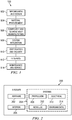
Figure 1 is an illustration of an aircraft manufacturing and service method in which an advantageous embodiment may be implemented; -
Figure 2 is an illustration of an aircraft depicted in accordance with an advantageous embodiment; -
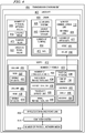
Figure 3 is an illustration of a block diagram of a data processing system depicted in accordance with an advantageous embodiment; -
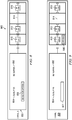
Figure 4 is an illustration of a block diagram of a transmission environment depicted in accordance with an advantageous embodiment; -
Figure 5 is an illustration of an aircraft cabin depicted in accordance with an advantageous embodiment; -
Figure 6 is an illustration of passenger service units depicted in accordance with an advantageous embodiment; -
Figure 7 is an illustration of passenger service units depicted in accordance with an advantageous embodiment; -
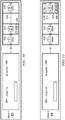
Figure 8 is an illustration of a portion of a cabin at a first point in time for identifying addresses depicted in accordance with an advantageous embodiment; -
Figure 9 is an illustration of a portion of a cabin at a second point in time for identifying addresses depicted in accordance with an advantageous embodiment; -
Figure 10 is an illustration of a portion of a cabin at a third point in time for identifying addresses depicted in accordance with an advantageous embodiment; -
Figure 11 is an illustration of a portion of a cabin at a fourth point in time for indentifying addresses depicted in accordance with an advantageous embodiment; -
Figure 12 is an illustration of a portion of a cabin at a fifth point in time for identifying addresses depicted in accordance with an advantageous embodiment; -
Figure 13 is an illustration of a portion of a cabin at a sixth point in time for identifying addresses depicted in accordance with an advantageous embodiment; -
Figure 14 is an illustration of a portion of a cabin at a seventh point in time for identifying addresses depicted in accordance with an advantageous embodiment; -
Figure 15 is a flowchart of a process for transmitting messages in accordance with an advantageous embodiment; -
Figure 16 is a flowchart of an additional process for transmitting messages in accordance with an advantageous embodiment; and -
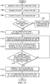
Figure 17 is a flowchart of a process for identifying an address for each transceiver unit in accordance with an advantageous embodiment. - Referring more particularly to the drawings, embodiments of the disclosure may be described in the context of aircraft manufacturing and
service method 100 as shown inFigure 1 andaircraft 200 as shown inFigure 2 . Turning first toFigure 1 , an illustration of an aircraft manufacturing and service method is depicted in accordance with an advantageous embodiment. During pre-production, aircraft manufacturing andservice method 100 may include specification anddesign 102 ofaircraft 200 inFigure 2 andmaterial procurement 104. - During production, component and
subassembly manufacturing 106 andsystem integration 108 ofaircraft 200 inFigure 2 takes place. Thereafter,aircraft 200 inFigure 2 may go through certification anddelivery 110 in order to be placed inservice 112. While in service by a customer,aircraft 200 inFigure 2 is scheduled for routine maintenance andservice 114, which may include modification, reconfiguration, refurbishment, and other maintenance or service. - In some advantageous embodiments, components are installed aboard the aircraft during
system integration 108. The components include any combination of a number of computer systems, a number of transceiver units, a number of network media or other suitable components. Installing the components comprises positioning the components in advantageous locations aboard the aircraft. For example, the components may be installed such that a computer system is located at the front of a column of passenger seats, a computer system is located behind the column of passenger seats, and a transceiver unit is located above each row of passenger seats in the column. - In other advantageous embodiments, components are installed aboard the aircraft during maintenance and
service 114. In such advantageous embodiments, panels in the cabin may be moved, added, replaced, or removed. During maintenance andservice 114, wiring may be removed from the aircraft in order to reduce the weight of the aircraft. Panels with wireless communication links may be installed to replace the wiring. Installing the panels with wireless communication links avoids the cost and time of installing and moving additional wiring in future passenger seating changes. - In these examples, "a number of" an item means one or more of the item. For example, "a number of transceiver units" means one or more transceiver units.
- Each of the processes of aircraft manufacturing and
service method 100 may be performed or carried out by a system integrator, a third party, and/or an operator. In these examples, the operator may be a customer. For the purposes of this description, a system integrator may include, without limitation, any number of aircraft manufacturers and majorsystem subcontractors; a third party may include, without limitation, any number of vendors, subcontractors, and suppliers; and an operator may be an airline, leasing company, military entity, service organization, and so on. - With reference now to
Figure 2 , an illustration of an aircraft is depicted in which an advantageous embodiment may be implemented. In this example,aircraft 200 is produced by aircraft manufacturing andservice method 100 inFigure 1 and may includeairframe 202 with a plurality ofsystems 204 and interior 206. Examples ofsystems 204 include one or more ofpropulsion system 208,electrical system 210,hydraulic system 212, andenvironmental system 214. Any number of other systems may be included. Although an aerospace example is shown, different advantageous embodiments may be applied to other industries, such as the automotive industry. - Systems and methods embodied herein may be employed during at least one of the stages of aircraft manufacturing and
service method 100 inFigure 1 . As described, some advantageous embodiments may be installed, configured, maintained, replaced, and/or removed during component andsubassembly manufacturing 106. However, other advantageous embodiments may be installed, configured, maintained, replaced, and/or removed during a number of other stages in aircraft manufacturing andservice method 100. - Additionally, components of the system and methods embodied herein may be installed, configured, maintained, and/or replaced in
interior 206 and/or removed frominterior 206. However, the components may also be located in other portions ofaircraft 200. - As used herein, the phrase "at least one of", when used with a list of items, means that different combinations of one or more of the listed items may be used and only one of each item in the list may be needed. For example, "at least one of item A, item B, and item C" may include, for example, without limitation, item A or item A and item B. This example also may include item A, item B, and item C or item B and item C.
- In one illustrative example, components or subassemblies produced in component and
subassembly manufacturing 106 inFigure 1 may be fabricated or manufactured in a manner similar to components or subassemblies produced whileaircraft 200 is inservice 112 inFigure 1 . As yet another example, a number of system embodiments, method embodiments, or a combination thereof may be utilized during production stages, such as component andsubassembly manufacturing 106 andsystem integration 108 inFigure 1 . A number, when referring to items, means "one or more items". For example, a "number of system embodiments" is one or more system embodiments. A number of system embodiments, method embodiments, or a combination thereof may be utilized whileaircraft 200 is inservice 112 and/or during maintenance andservice 114 inFigure 1 . The use of a number of the different advantageous embodiments may substantially expedite the assembly of and/or reduce the cost ofaircraft 200. - Turning now to
Figure 3 , an illustration of a diagram of a data processing system is depicted in accordance with an illustrative embodiment. In this illustrative example,data processing system 300 includescommunications fabric 302, which provides communications betweenprocessor unit 304,memory 306,persistent storage 308,communications unit 310, input/output (I/O)unit 312, anddisplay 314. -
Processor unit 304 serves to execute instructions for software that may be loaded intomemory 306.Processor unit 304 may be a number of processors, may be a multi-processor core, or some other type of processor, depending on the particular implementation. A number, as used herein with reference to an item, means one or more items. Further,processor unit 304 may be implemented using a number of heterogeneous processor systems in which a main processor is present with secondary processors on a single chip. As another illustrative example,processor unit 304 may be a symmetric multi-processor system containing multiple processors of the same type. -
Memory 306 andpersistent storage 308 are examples ofstorage devices 316. A storage device is any piece of hardware that is capable of storing information, such as, for example, without limitation, data, program code in functional form, and/or other suitable information either on a temporary basis and/or a permanent basis.Memory 306, in these examples, may be, for example, a random access memory or any other suitable volatile or non-volatile storage device.Persistent storage 308 may take various forms depending on the particular implementation. For example,persistent storage 308 may contain one or more components or devices. For example,persistent storage 308 may be a hard drive, a flash memory, a rewritable optical disk, a rewritable magnetic tape, or some combination of the above. The media used bypersistent storage 308 also may be removable. For example, a removable hard drive may be used forpersistent storage 308. -
Communications uni 310, in these examples, provides communications with other data processing systems or devices. In these examples,communications unit 310 is a network interface card.Communications unit 310 may provide communications through the use of either or both physical and wireless communications links. - Input/
output unit 312 allows for input and output of data with other devices that may be connected todata processing system 300. For example, input/output unit 312 may provide a connection for user input through a keyboard, a mouse, and/or some other suitable input device. Further, input/output unit 312 may send output to a printer.Display 314 provides a mechanism to display information to a user. - Instructions for the operating system, applications, and/or programs may be located in
storage devices 316, which are in communication withprocessor unit 304 throughcommunications fabric 302. In these illustrative examples, the instructions are in a functional form onpersistent storage 308. These instructions may be loaded intomemory 306 for execution byprocessor unit 304. The processes of the different embodiments may be performed byprocessor unit 304 using computer implemented instructions, which may be located in a memory such asmemory 306. - These instructions are referred to as program code, computer usable program code, or computer readable program code that may be read and executed by a processor in
processor unit 304. The program code in the different embodiments may be embodied on different physical or computer readable storage media such asmemory 306 orpersistent storage 308. -
Program code 318 is located in a functional form on computerreadable media 320 that is selectively removable and may be loaded onto or transferred todata processing system 300 for execution byprocessor unit 304.Program code 318 and computerreadable media 320 formcomputer program product 322 in these examples. In one example, computer readable media. 320 may be computerreadable storage medium 324 or computerreadable signal medium 326. Computerreadable storage medium 324 may include, for example, an optical or magnetic disc that is inserted or placed into a drive or other device that is part ofpersistent storage 308 for transfer onto a storage device, such as a hard drive that is part ofpersistent storage 308. Computerreadable storage medium 324 also may take the form of a persistent storage, such as a hard drive, a thumb drive, or a flash memory that is connected todata processing system 300. In some instances, computerreadable storage medium 324 may not be removable fromdata processing system 300. In these illustrative examples, computerreadable storage medium 324 is a non-transitory computer readable storage medium. - Alternatively,
program code 318 may be transferred todata processing system 300 using computerreadable signal medium 326. Computer readable signal medium 326 may be, for example, a propagated data signal containingprogram code 318. For example, computer readable signal medium 326 may be an electromagnetic signal, an optical signal, and/or any other suitable type of signal. These signals may be transmitted over communications links, such as wireless communications links, optical fiber cable, coaxial cable, a wire, and/or any other suitable type of communications link. In other words, the communications link and/or the connection may be physical or wireless in the illustrative examples. - In some illustrative embodiments,
program code 318 may be downloaded over a network topersistent storage 308 from another device or data processing system through computerreadable signal medium 326 for use withindata processing system 300. For instance, program code stored in a computer readable storage medium in a server data processing system may be downloaded over a network from the server todata processing system 300. The data processing system providingprogram code 318 may be a server computer, a client computer, or some other device capable of storing and transmittingprogram code 318. - The different components illustrated for
data processing system 300 are not meant to provide architectural limitations to the manner in which different embodiments may be implemented. The different illustrative embodiments may be implemented in a data processing system including components in addition to or in place of those illustrated fordata processing system 300. Other components shown inFigure 3 can be varied from the illustrative examples shown. The different embodiments may be implemented using any hardware device or system capable of executing program code. As one example, the data processing system may include organic components integrated with inorganic components and/or may be comprised entirely of organic components excluding a human being. For example, a storage device may be comprised of an organic semiconductor. - As another example, a storage device in
data processing system 300 is any hardware apparatus that may store data.Memory 306,persistent storage 308, and computerreadable media 320 are examples of storage devices in a tangible form. - In another example, a bus system may be used to implement
communications fabric 302 and may be comprised of one or more buses, such as a system bus or an input/output bus. Of course, the bus system may be implemented using any suitable type of architecture that provides for a transfer of data between different components or devices attached to the bus system. Additionally, a communications unit may include one or more devices used to transmit and receive data, such as a modem or a network adapter. Further, a memory may be, for example,memory 306 or a cache, such as a cache found in an interface and memory controller hub that may be present incommunications fabric 302. - The different advantageous embodiments recognize and take into account a number of different considerations. For example, the different advantageous embodiments recognize that aircraft commonly have a number of networks. The number of networks take the form of different physical media. For example, the aircraft may be equipped with two Ethernet networks, a controller area network (CAN) bus network, and a discrete signal network. Each network may be used for a different purpose. For example, a CAN bus network may be used to monitor the health of oxygen distribution systems. Components of the oxygen distribution systems are located in passenger service units. The passenger service units are located above each row of passenger seats on the aircraft.
- The different advantageous embodiments also recognize and take into account that the passenger service units above each row of passenger seats may be moved and/or reconfigured during the operational life of the aircraft. For example, the passenger service units may be moved when a new seating plan is used in the aircraft. In other words, a new seating plan changes the pitch between seats. The pitch is the space between seats in a column. The seating plan may be changed to allow for more seats to be installed in the aircraft. Alternatively, the seating plan may be changed to allow for each seat to be surrounded by additional space. Passenger service units may be connected to the networks in the aircraft using a number of wires.
- The different advantageous embodiments recognize and take into account that the number of wires may not have extra wire to allow a connection to the passenger service panel to be moved without reworking the number of wires and/or the connection to the passenger service panel. In some examples, a new connector must be designed and/or wires must be rerun from another location. Reworking the wiring in the aircraft is disadvantageous because this process increases the cost of changing the seat plan on the aircraft. Alternatively, additional wire may be installed during the initial configuration of the aircraft. Installing additional wire during initial configuration of the aircraft is disadvantageous, however, because the extra cable adds weight to the aircraft and decreases fuel economy.
- The different advantageous embodiments also recognize and take into account that wireless communication between the passenger service units and the networks on the aircraft allow the passenger service units to be moved during a seat plan change without reworking wiring and/or connectors.
- Thus, the different advantageous embodiments provide a system and method for transmitting messages. In one advantageous embodiment, a system comprising a number of transceiver units, a first computer system, and a second computer system is provided. The number of transceiver units are configured for use in a cabin of an aircraft, each of the number of transceiver units being configured to receive a number of messages and transmit the number of messages to a subsequent transceiver unit, wherein the subsequent transceiver unit is identified based on a physical position of the each of the number of transceiver units to one another. The first computer system is configured for use in the cabin, the first computer system being configured to receive the number of messages on a first number of physical network media and transmit the number of messages over a first wireless communications link to a first transceiver unit in the number of transceiver units. The second computer system is configured for use in the aircraft cabin, the second computer system being configured to receive the number of messages over a second wireless communications link from a second transceiver unit in the number of transceiver units, the second computer system being further configured to transmit the number of messages received over the second wireless communications link on a second number of physical network media corresponding to the first number of physical network media.
- Turning now to
Figure 4 , an illustration of a transmission environment is depicted in accordance with an advantageous embodiment.Transmission environment 400 may be implemented inaircraft 200 inFigure 2 . - In these examples,
transmission environment 400 includesaircraft 402. Of course,transmission environment 400 may also contain other vehicles or locations that contain networks. For example, transmission environment may comprise a building and/or an automobile. -
Aircraft 402 is discussed in these examples. However,aircraft 402 is a non-limiting example of a vehicle in accordance with an advantageous embodiment. Other vehicles may be used in addition to or in place ofaircraft 402. A vehicle, as used herein, is a device used for transporting people and/or objects. For example, the vehicle may be a bus, a train, a boat, or any other suitable vehicle that has seats configured in rows and/or columns. -
Cabin 404 is present withinaircraft 402.Cabin 404 is an area suitable for humans or objects to be present during operation of the aircraft.Cabin 404 consists of any combination of a passenger cabin, a cockpit, and a cargo bay. In this advantageous embodiment,cabin 404 contains number ofphysical network media 406,computer system 408, wireless communications link 410,seats 412,computer system 414, and number ofphysical network media 416. - Number of physical network media. 406 make up a number of networks present in
cabin 404. The networks are used for communications between systems onboardaircraft 402. In these examples, number ofphysical network media 406 compriseEthernet media 418,CAN bus media 420, anddiscrete signal media 422. CAN bus media is a controller area network bus.Discrete signal media 422 is a media on which a voltage on the media is varied such that the changes in voltage are recognized by devices ondiscrete signal media 422. Of course, number ofphysical network media 406 may consist of additional and/or different types of media. - Number of
physical network media 406 are connected tocomputer system 408.Computer system 408 is a data processing system.Computer system 408 may be an example implementation ofdata processing system 300 fromFigure 3 . Of course, some components fromdata processing system 300 may not be present incomputer system 408 and/or additional components may be present incomputer system 408.Computer system 408 is configured to send and receive data using wireless communications link 410. - Wireless communications link 410 is a substance through which signals can travel. Wireless communications link 410 is a part of a network. In these examples, however, wireless communications link 410 is a different type of media than number of
physical network media 406. For example, number ofphysical network media 406 may compriseEthernet media 418,CAN bus media 420, anddiscrete signal media 422, while wireless communications link 410 isinfrared link 424. Number ofpanels 426 are associated withseats 412. - A first component is considered to be associated with a second component by being secured to the second component, bonded to the second component, fastened to the second component, and/or connected to the second component in some other suitable manner. The first component also may be connected to the second component through using a third component. The first component is also considered to be associated with the second component by being formed as part of and/or an extension of the second component.
- In these examples,
seats 412 are positioned in rows, such asrow 464. Row 464 contains number ofseals 462. Number ofpanels 426 are located above number ofseats 462 such that a panel corresponds to number ofseats 462 associated with the panel. Row 464 is a part ofcolumn 460.Column 460 andcolumn 466 each consist of rows of seats, such asrow 464 androw 468, respectively.Column 460 is separated from another column., such ascolumn 466, by a walkway or aisle. Additional columns may be present incabin 404. - In other words,
column 460 containsrow 464. Row 464 contains number ofseats 462. Number ofseats 462 are associated with a panel in number ofpanels 426. Thus, in some advantageous embodiments,row 464 may be associated with more than one panel in number ofpanels 426. - Likewise,
column 466 containsrow 468. Row 468 contains number ofseats 470. Number ofseats 470 are associated with a panel in number ofpanels 426. Thus, in some advantageous embodiments,row 468 may be associated with more than one panel in number ofpanels 426. - In these examples, each panel in number of
panels 426 is apassenger service unit 428. A passenger service unit is a device that provides a number of services to a number of passengers sitting in number ofseats 462. For example,passenger service units 428 may provide a switchable light, ventilation, and/or oxygen distribution through a mask. - Number of
panels 426 are associated with number oftransceiver units 456. In one advantageous embodiment, each panel is associated with onetransceiver unit 430 in number oftransceiver units 456. Number oftransceiver units 456 are devices configured to receive and transmit messages on wireless communications link 410. In these examples, wireless communications link 410 isinfrared link 424. In some advantageous embodiments, number oftransceiver units 456 are computer systems, likecomputer system 408 and/ordata processing system 300 inFigure 3 . In other advantageous embodiments, number oftransceiver units 456 do not contain some components ofdata processing system 300. For example, number oftransceiver units 456 may or may not containstorage devices 316 as inFigure 3 . -
Computer system 414 is a computer system likecomputer system 408.Computer system 414 is connected to number oftransceiver units 456 using wireless communications link 458.Computer system 414 is also connected to number ofphysical network media 416. In these examples, number ofphysical network media 416 are the same media as number ofphysical network media 406. However, in other advantageous embodiments, number ofphysical network media 416 may be different types of media than number ofphysical network media 406. -
Transmission environment 400 may be used to transmit and receive data across the different networks and media contained intransmission environment 400. Number ofmessages 432 are a number of data communications. The number of data communications may be transmitted across number ofphysical network media 406 to reachcomputer system 408, or may be originally transmitted bycomputer system 408. -
Computer system 408 either receives data from other devices on number ofphysical network media 406 orcomputer system 408 may create number ofmessages 432 for transmission. In advantageous embodiments in which data is received on number ofphysical network media 406,computer system 408 combines the data into number ofmessages 432.Computer system 408 may combine the data into number ofmessages 432 by multiplexing the data for transmission on wireless communications link 410. The data may be intended for a number of different devices on the various networks made up of number ofphysical network media 406. -
Computer system 408 then transmits number ofmessages 432 to number oftransceiver units 456 using wireless communications link 410.Computer system 408 transmits number ofmessages 432 to number oftransceiver units 456 by transmitting an infrared representation of number ofmessages 432 oninfrared link 424. A transceiver unit, such astransceiver unit 430, receives number ofmessages 432. The transceiver unit that receives number ofmessages 432 then transmits number ofmessages 432 tosubsequent transceiver unit 434. - In these examples, number of
transceiver units 456 are configured to send and receiver number ofmessages 432 to and from each other andcomputer systems transceiver units 456 are positioned inphysical position 436 relative to each other. In other words,subsequent transceiver unit 434 is identified by the transceiver unit that most recently received number ofmessages 432. - In this advantageous embodiment, physical position relative to each other means that each transceiver unit in number of
transceiver units 428 is within line ofsight 438 ofsubsequent transceiver unit 434. In this advantageous embodiment, number oftransceiver units 428 form a column and each of number oftransceiver units 456 receives number ofmessages 432 from one direction in the column and transmits number ofmessages 432 tosubsequent transceiver unit 434 in the column.Subsequent transceiver unit 434 then transmits number ofmessages 432 to anothersubsequent transceiver unit 434 using line ofsight 438 in the column of number oftransceiver units 456. In these examples, anothersubsequent transceiver unit 434 is associated with another panel in number ofpanels 426. Number oftransceiver units 456 may comprise two transceivers, with each transceiver directed opposite the other transceiver. - Number of
messages 432 is transmitted and received by number oftransceiver units 456 from the end of the column closest tocomputer system 408 to the end of the column farthest fromcomputer system 408.Final transceiver unit 440 receives number ofmessages 432 once all other transceiver units in number oftransceiver units 456 have received number ofmessages 432. In other words,final transceiver unit 440 is identified as the last transceiver unit in number oftransceiver units 456 to receive number ofmessages 432 from another transceiver unit. -
Final transceiver unit 440 then transmitsmessages 432 tocomputer system 414 using wireless communications link 458. Wireless communications link 458 may be of the same type as wireless communications link 410. In these examples, wireless communications link 458 is an infrared link. Oncecomputer system 414 receives number ofmessages 432 fromfinal transceiver unit 440,computer system 414 decodes number ofmessages 432.Computer system 414 then recreates the original messages that composed number ofmessages 432 on the corresponding media in number ofphysical network media 416. In these advantageous embodiments,computer system 414 recreates the data from number ofmessages 432 on a medium in number ofphysical network media 416 that matches the medium on which the data was received atcomputer system 408 on number ofphysical network media 406. For example, if data fromEthernet media 418 was contained in number ofmessages 432,computer system 408 recreates the data on an Ethernet medium in number ofphysical network media 416.Computer system 408 may encode an identifier for number ofphysical network media 406 on which the data was received. - In some advantageous embodiments, number of
messages 432 also contains data intended for receipt and/or processing bytransceiver unit 430. In such an advantageous embodiment, each of the number oftransceiver units 456 are addressed withaddress 442.Address 442 is assigned totransceiver unit 430 and is unique among number oftransceiver units 456. To assignaddress 442 to each of number oftransceiver units 456,source computer system 443 transmitscode 444.Source computer system 443 is a computer system configured to generatecode 444. In some advantageous embodiments,source computer system 443 iscomputer system 408.Code 444 may contain information recognized by number of transceiver units to be coded to identifyaddress 442. -
Code 444 is transmitted among number oftransceiver units 456 in the same manner as number ofmessages 432. In other words,code 444 is received bytransceiver unit 430 and transmitted tosubsequent transceiver unit 434 inorder 446.Order 446 is the sequence in which number oftransceiver units 456 have line ofsight 438 with one another.Code 444 is transmitted alongorder 446 untilfinal transceiver unit 440 receivescode 444. - When
code 444 is received byfinal transceiver unit 440,final transceiver unit 440 transmitsvalue 448 inreverse 450 oforder 446. In other words,value 448 is transmitted and received by number oftransceiver units 456 ininverted order 446. Eachtransceiver unit 430 in number oftransceiver units 456 modifiesvalue 448 and transmits modifiedvalue 448 to thenext transceiver unit 430 inreverse 450 oforder 446. In one advantageous embodiment,final transceiver unit 440 transmitsvalue 448 of "1" and eachtransceiver unit 430 increments value 448 by one. Once thefirst transceiver unit 430 to receivecode 444 receivesvalue 448,value 448 is transmitted tocomputer system 408. Eachtransceiver unit 430 stores address 442 fortransceiver unit 430.Source computer system 443 setssize 452 of number ofbuffers 454 tovalue 448. Number ofbuffers 454 store number ofmessages 432 prior to transmitting bycomputer system 408 and/or while wireless communications link 410 is in use bytransceiver unit 430 orcomputer system 414. - The illustration of
aircraft 402 intransmission environment 400 is not meant to imply physical or architectural limitations to the manner in which different features may be implemented. Other components in addition to and/or in place of the ones illustrated may be used. Some components may be unnecessary in some advantageous embodiments. Also, the blocks are presented to illustrate some functional components. One or more of these blocks may be combined and/or divided into different blocks when implemented in different advantageous embodiments. - For example,
additional computer systems 414 may be located betweentransceiver units 430 in number oftransceiver units 456.Computer system 414 may also setsize 452 ofbuffers 454 usingvalue 448. In such an advantageous embodiment,computer system 408 may sendvalue 448 tocomputer system 414 on wireless communications link 410 through number oftransceiver units 456. -
Figures 5 and6 depict illustrations of an aircraft cabin containing a number of components present in some advantageous embodiments.Figure 5 presents an overview of the cabin, andFigure 6 presents a more detailed view of the computer systems and transceiver units. - Turning now to
Figure 5 , an illustration of an aircraft cabin is depicted in accordance with an advantageous embodiment.Cabin 500 is an example implementation ofcabin 404 inFigure 4 .Cabin 500 containsseats 502.Seats 502 are an example implementation ofcolumn 460 withinseats 412 inFigure 4 . -
Cabin 500 also containspassenger service units 504. Number ofpassenger service units 504 are example implementations ofpassenger service units 428 inFigure 4 . In this advantageous embodiment, each seat inseats 502 is associated with one or more passenger service unit in number ofpassenger service units 504. - In this advantageous embodiment, each seat is associated with two passenger service units. A passenger service unit is associated with a seat when the passenger service unit provides a number of services for the seat and/or a passenger sitting in the seat. For example, both
passenger service unit 506 andpassenger service unit 514 are associated withseat 530. In the depicted example,passenger service units passenger service units - In these examples, a passenger service unit, such as
passenger service unit 506, is located within a panel such aspanel 508.Panel 508 is an example implementation of a panel in number ofpanels 426. In the depicted example,panel 508 is associated withseat 530. However,panel 508 may also be associated with other seats in the same row asseat 530 that are not depicted in this illustration. - In this depicted example, messages arrive at
computer system 510 onmedia 512.Computer system 510 is an example implementation ofcomputer system 408 andmedia 512 are example implementations of number ofphysical network media 406 inFigure 4 . In these illustrative examples,computer system 510 has an infrared transceiver.Computer system 510 combines the messages from thedifferent media 512 and uses the infrared transceiver to tirelessly transmit the messages topassenger service unit 506. - In the illustrative examples,
passenger service unit 506 receives the messages and transmits the messages topassenger service unit 514.Passenger service unit 506 may receive the messages on a first infrared transceiver directed towardcomputer system 510 to include the line of sight withcomputer system 510.Passenger service unit 506 may use a second transceiver directed towardpassenger service unit 514 to transmit the messages topassenger service unit 514.Passenger service unit 506 may be connected to an electricalpower distribution system 524 usingwire 526. In the depicted example,wire 526 provides electrical power for all of number ofpassenger service units 504. -
Passenger service unit 514 receives the messages and transmits the messages topassenger service unit 516.Passenger service unit 516 receives the messages and transmits the messages topassenger service unit 518.Passenger service unit 518 receives the messages and transmits the messages topassenger service unit 532.Passenger service unit 532 receives the messages and transmits the messages topassenger service unit 534.Passenger service unit 534 receives the messages and transmits the messages topassenger service unit 536.Passenger service unit 536 receives the messages and transmits the messages topassenger service unit 538.Passenger service unit 538 receives the messages and transmits the messages tocomputer system 520. - In response to receiving the messages,
computer system 520 decodes the messages and uses information in the messages to identify the type of media on which the message was received.Computer system 520 recreates messages on number ofphysical media 522 such that the messages are transmitted on the same type of physical media on which they were received. In some advantageous embodiments, multiple physical media of the same type are present. In such advantageous embodiments, an additional identifier may be encoded in the messages to identify the networks on which the messages were received. -
Portion 528 ofcabin 500 is presented with additional detail inFigure 6 . - Turning now to
Figure 6 , an illustration of another view of an aircraft cabin is depicted in accordance with an advantageous embodiment.Portion 600 is a more detailed view ofportion 528 inFigure 5 . -
Computer system 510 combines the messages from thedifferent media 512 and uses an infrared transceiver to wirelessly transmit the messages topassenger service unit 506.Passenger service units 506 receives the messages and transmits the messages topassenger service unit 514.Passenger service unit 506 may receive the messages on a first infrared transceiver directed towardcomputer system 510 to include the line of sight withcomputer system 510.Passenger service unit 506 may use a second transceiver directed towardpassenger service unit 514 to transmit the messages topassenger service unit 514.Links 602 represent infrared links in this illustrative example. However, additionalpassenger service units 506 may be inserted in the physical area traveled bylinks 602 to connect additionalpassenger service units 506 to the system. -
Passenger service unit 514 receives the messages and transmits the messages topassenger service unit 516.Passenger service unit 516 receives the messages and transmits the messages topassenger service unit 518.Passenger service unit 518 receives the messages and transmits the messages topassenger service unit 532.Passenger service unit 532 receives the messages and transmits the messages topassenger service unit 534.Passenger service unit 534 receives the messages and transmits the messages topassenger service unit 536.Passenger service unit 536 receives the messages and transmits the messages topassenger service unit 538.Passenger service unit 538 receives the messages and transmits the messages tocomputer system 520.Computer system 520 decodes the messages and uses information in the messages to identify the type of media on which the message was received.Computer system 520 recreates messages on number ofphysical media 522 such that the messages are transmitted on the same type of physical media on which they were received. - Turning now to
Figure 7 , an illustration of passenger service units is depicted in accordance with an advantageous embodiment.Area 700 may be a portion of an aircraft cabin, such ascabin 500 inFigure 5 . - In this advantageous embodiment, messages are received on number of
physical media 701. For example, messages may be received on four Ethernet media and a discrete signal media.Computer system 702 is an example implementation ofcomputer system 408 inFigure 4 .Computer system 702 combines the messages by multiplexing the messages and transmitting the messages tocommunications unit 704.Communications unit 704 is a transceiving device that processes messages forpassenger service unit 706.Passenger service unit 706 is another computer system associated withcommunications unit 704.Passenger service unit 706 may be an example implementation ofdata processing system 300 inFigure 3 . In this advantageous embodiment,communications units 704 andpassenger service unit 706 collectively formtransceiver unit 722.Transceiver unit 722 is an example implementation oftransceiver unit 430 inFigure 4 . -
Transceiver unit 722 usescommunications unit 704 to transmit the messages tocommunications units 708.Communications unit 708 is associated with bothpassenger service unit 710 andpassenger service unit 712. In this advantageous embodiment,passenger service unit 710 andpassenger service unit 712 may each have a unique address in the data processing system, such asdata processing system 300. Additionally,communications unit 708 used by bothpassenger service unit 710 andpassenger service unit 712 may have a unique address on the infrared link. Thus,passenger service unit 710 andpassenger unit 712 may both usecommunications unit 708, with each ofpassenger service unit 710,passenger service unit 712, andcommunications unit 708 having a unique address in the data processing system. -
Communications unit 708 transmits the messages tocommunications unit 714.Communications unit 714 is associated withpassenger service unit 716.Communications unit 714 andpassenger service unit 716 collectively formtransceiver unit 724.Transceiver unit 724 usescommunications unit 714 to transmit the messages tocomputer system 718.Computer system 718 decodes the messages and identifies the media in number ofphysical media 720 that corresponds to the media in number ofphysical media 701 on which the message was received.Computer system 718 then transmits the message on the identified medium. -
Figures 8-14 illustrate an example of identifying an address for each of the number of transceiver units in accordance with an advantageous embodiment. Each figure inFigures 8-14 illustrates a point in time later than the previous figure. In other words,Figures 8-14 illustrate sequential points in time. - Turning now to
Figure 8 , an illustration of a portion of a cabin at a first point in time for identifying addresses is depicted in accordance with an advantageous embodiment.Portion 800 is an example implementation ofportion 700 inFigure 7 .Portion 800 containscomputer system 802, link 814, andtransceiving units Computer system 802 is an example implementation ofcomputer system 408 inFigure 4 . Addresses may be identified for transceivingunits transceiving units -
Computer system 802 contains atransmission buffer 804 and a receivingbuffer 806. Before the quantity of addresses for transceiving units is known, thetransmission buffer 804 is atsize 1. Receivingbuffer 806 is at size 0.Computer system 802 generatescode 808 and stores code 808 intransmission buffer 804.Code 808 is an example implementation ofcode 444 inFigure 4 . - Next in
Figure 9 , an illustration of a portion of a cabin at a second point in time for identifying addresses is depicted in accordance with an advantageous embodiment.Computer system 802 transmitscode 808 totransceiver unit 810 and removescode 808 fromtransmission buffer 804. - With reference now to
Figure 10 , an illustration of a portion of a cabin at a third point in time for identifying addresses is depicted in accordance with an advantageous embodiment.Transceiver unit 810 transmitscode 808 totransceiver unit 812. - In
Figure 11 , an illustration of a portion of a cabin at a fourth point in time for identifying addresses is depicted in accordance with an advantageous embodiment.Transceiver unit 812 transmitscode 808 totransceiver unit 816 usinglink 814.Link 814 is an example implementation oflink 602 inFigure 6 .Link 814 allows additional transceiver units to be installed in the physical space used bylink 814 without reworking connectors or wiring. -
Transceiver unit 816 detects that there are no additional transceiver units within range.Transceiver unit 816 then generatesvalue 1102.Value 1102 is "1" in these examples.Transceiver unit 816 discardscode 808 but savesvalue 1102 as the address oftransceiver unit 816.Transceiver unit 816 then transmitsvalve 1102 totransceiver unit 812. - Turning now to
Figure 12 , an illustration of a portion of a cabin at a fifth point in time for identifying addresses is depicted in accordance with an advantageous embodiment.Transceiver unit 812 receivesvalue 1102 and increments value 1102 to "2" to formvalue 1202.Transceiver unit 812 savesvalue 1202 as the address fortransceiver unit 812 and transmitsvalue 1202 totransceiver unit 810. - Next in
Figure 13 , an illustration of a portion of a cabin at a sixth point in time for identifying addresses is depicted in accordance with an advantageous embodiment.Transceiver unit 810 receivesvalue 1202 and increments value 1202 to "3" to formvalve 1302.Transceiver unit 810 savesvalue 1302 as the address fortransceiver unit 812 and transmitsvalue 1302 tocomputer system 802. - Turning to
Figure 14 , an illustration of a portion of a cabin at a seventh point in time for identifying addresses is depicted in accordance with an advantageous embodiment.Computer system 802 receivesvalue 1302 of "3" and sets the size oftransmission buffer 804 and receivingbuffer 806 to a 3. - In
Figure 15 , an illustration flowchart of a process for transmitting messages is depicted in accordance with an advantageous embodiment. The process may be performed intransmission environment 400 bycomputer system 802, number oftransceiver units 456 andcomputer system 414 inFigure 4 . - The process begins by receiving, by a first computer system configured for use in a cabin of an aircraft, a number of messages on a first number of physical network media (operation 1502). The computer system may be a data processing system, such as
data processing system 300 inFigure 3 . A physical network medium is a physical substance capable of carrying data from one device to another. Examples of physical network media include Ethernet, CAN bus, and discrete signal media. - The process then transmits the number of messages over a first wireless communications link to a first transceiver unit in a number of transceiver units (operation 1504). The wireless communications link may be an infrared link.
- The process then receives, by the number of transceiver units configured for use in the cabin, the number of messages and transmits the number of messages to a subsequent transceiver unit (operation 1506). The subsequent transceiver unit is identified based on a physical position of the each of the number of transceiver units to one another.
- The process then receives, by a second computer system configured for use in the aircraft cabin, the number of messages over a second wireless communications link from a second transceiver unit in the number of transceiver units (operation 1508).
- The process transmits the number of messages on a second number of physical network media corresponding to the first number of physical network media (operation 1510). The second number of physical network media may be of the same types as the first physical network media. The second computer system selects a physical network media from the second number of physical network media that corresponds to the first number of physical network media based on the network on which the message was received by the first computer system. For example, if the message was received at the first computer system on an Ethernet network, the second computer system recreates the data on an Ethernet network in the second number of physical network media. In some advantageous embodiments, an identifier is included in the message that indicates on which network the second computer system is to recreate the message. The process terminates thereafter.
- Turning now to
Figure 16 , a flowchart of an additional process for transmitting messages is depicted in accordance with an advantageous embodiment. The process may be performed intransmission environment 400 bycomputer system 802, number oftransceiver units 456 andcomputer system 414 inFigure 4 . - The process begins by receiving data at a first computer system on multiple networks (operation 1602). The computer system may be a data processing system, such as
data processing system 300 inFigure 3 . - The process then multiplexes the data into a number of messages using infrared (operation 1604). The process then receives the number of messages at a transceiver unit in line of sight of the sender (operation 1606).
- The process then determines whether another transceiver unit is within range (operation 1608). If the process determines that another transceiver unit is within range, the process transmits the number of messages to the next transceiver unit (operation 1614) and the process returns to
operation 1606. If the process determines that another transceiver is within range atoperation 1608, the process transmits the number of messages to a second computer system (operation 1610). The process then recreates the messages on a network connected to the second computer system that corresponds to the network on which the messages were first received (operation 1612). The process terminates thereafter. - Turning now to
Figure 17 , a flowchart of a process for identifying an address for each transceiver unit is depicted in accordance with an advantageous embodiment. The process may be performed intransmission environment 400 bycomputer system 802, number oftransceiver units 456 andcomputer system 414 inFigure 4 . - The process begins by generating a code at a first computer system (operation 1702). The computer system may be a data processing system, such as
data processing system 300 inFigure 3 . The code may be recognized by the transceiver units as an addressing code. - The process then transmits the code to a transceiver unit (operation 1704). The process may use an infrared link to transmit the code. The process then receives the code at the transceiver unit (operation 1706).
- The process then determines if an additional transceiver unit is within range (operation 1708). If the process determines that an additional transceiver is within range, the process transmits the code to the additional transceiver unit (operation 1722). The process then returns to
operation 1706. If the process determines that an additional transceiver unit is not within range atoperation 1708, the process sets the address of the final transceiver unit to a value of "1" (operation 1710). - The process transmits the value to the transceiver unit from which the transceiver unit received the code (operation 1712). The process then receives the value at a transceiver unit, increments the value, and sets the address of the transceiver unit to the new value (operation 1714).
- The process determines if the transceiver unit that most recently received the value received the code directly from the computer system (operation 1716). If the process determines that the transceiver unit that most recently received the value did not receive the code directly from the computer system, the process returns to
operation 1712. If the process determines that the transceiver unit that most recently received the value did receive the code directly from the computer system atoperation 1716, the process increments the value and transmits the value to the computer system (operation 1718). - The process then sets the transmission and receiving buffers of the computer system equal to the value (operation 1720) and the process terminates thereafter.
- The flowchart and block diagrams in the different depicted embodiments illustrate the architecture, functionality, and operation of some possible implementations of systems and methods in different advantageous embodiments. In this regard, each block in the flowchart or block diagrams may represent a module, segment, function, and/or a portion of an operation or step.
- In some alternative implementations, the function or functions noted in the block may occur out of the order noted in the figures. For example, in some cases, two blocks shown in succession may be executed substantially concurrently, or the blocks may sometimes be executed in the reverse order, depending upon the functionality involved. Also, other blocks may be added in addition to the illustrated blocks in a flowchart or block diagram.
- For example, the process may not perform
operation 1608 of particular number of transceiver units have been identified. Additionally, the process may negotiate a rate of transfer and/or a security protocol with the next transceiver unit atoperation 1610 prior to transmitting the number of messages. Additionally, the process may recreate the number of messages on a particular network atoperation 1510, or may recreate the messages on different networks based on a set of policies or rules. - Thus, the different advantageous embodiments allow the passenger service units to be moved to other locations without reworking wiring or connectors and reducing weight and maintenance costs. Units may also be added or removed from the system and the system automatically re-addresses the new and/or remaining units.
- Thus, the different advantageous embodiments provide a system and method for transmitting messages. In one advantageous embodiment, a system comprising a number of transceiver units, first computer system, and a second computer system is provided. The number of transceiver units are configured for use in a cabin of an aircraft, each of the number of transceiver units being configured to receive a number of messages and transmit the number of messages to a subsequent transceiver unit, wherein the subsequent transceiver unit is identified based on a physical position of the each of the number of transceiver units to one another. The first computer system is configured for use in the cabin, the first computer system being configured to receive the number of messages on a first number of physical network media and transmit the number of messages over a first wireless communications link to a first transceiver unit in the number of transceiver units. The second computer system is configured for use in the aircraft cabin, the second computer system being configured to receive the number of messages over a second wireless communications link from a second transceiver unit in the number of transceiver units, the second computer system being further configured to transmit the number of messages received over the second wireless communications link on a second number of physical network media corresponding to the first number of physical network media.
- The description of the different advantageous embodiments has been presented for purposes of illustration and description, and is not intended to be exhaustive or limited to the embodiments in the form disclosed. Many modifications and variations will be apparent to those of ordinary skill in the art. Further, different advantageous embodiments may provide different advantages as compared to other advantageous embodiments. The embodiment or embodiments selected are chosen and described in order to best explain the principles of the embodiments, the practical application, and to enable others of ordinary skill in the art to understand the disclosure for various embodiments with various modifications as are suited to the particular use contemplated.
Claims (14)
- A method of transmitting messages, the method comprising:receiving, by a first computer system (408) configured for use in a cabin (404) of a vehicle (402), a number of messages (432) on a first number of physical network media (406) and transmitting the number of messages over a first wireless communications link (410) to a first transceiver unit (430) in a number of transceiver units (456);receiving, by a subsequent transceiver unit (434) in the number of transceiver units configured for use in the cabin, the number of messages from the first transceiver unit, wherein the subsequent transceiver unit is identified based on a physical position (436) of the each of the number of transceiver units to one another; andreceiving, by a second computer system (414) configured for use in the cabin, the number of messages over a second wireless communications link (458) from the subsequent transceiver unit, wherein the second computer system transmits the number of messages received over the second wireless communications link on a second number of physical network media (416) corresponding to the first number of physical network media.
- The method of claim 1 further comprising:identifying an address (442) for each transceiver unit on the medium.
- The method of claim 2, wherein the first computer system is a source computer system, and wherein the step of identifying the address for the each computer system on the medium further comprises:transmitting a code (444) from the source computer system to a last transceiver unit (440) on the medium, wherein the each transceiver unit receives the code and repeats the code to another transceiver unit on the medium;responsive to receiving the code at a last transceiver unit on the medium, transmitting a value (448) to the source computer system, wherein the each computer system receives the value and increments the value prior to repeating the value to the another computer system; andreceiving the value at the source computer system.
- The method of claim 3 further comprising:setting a size (452) of a number of buffers (454) at the source computer system to the value.
- The method of claim 1 further comprising:receiving the number of messages from the first computer system at a transceiver unit; andtransmitting the number of messages from the transceiver unit to the second computer system.
- The method of claim 1, wherein the medium is a different medium than each of the first number of physical network media and each of the second number of physical network media.
- A system comprising:a first computer system configured for use in a cabin of a vehicle;a second computer system configured for use in the cabin;a number of transceiver units configured for use in the cabin, where the number of transceiver units are configured to wirelessly send and receive a number of messages to and from the first computer system, the second computer system and each other;wherein the system is configured to carry out the method of any of claims 1 to 6.
- The system of claim 7, wherein the vehicle is an aircraft and further comprising:the aircraft, wherein the cabin is located inside of the aircraft and the number of transceiver units are located substantially above a column of seats (460) onboard the aircraft.
- The system of claim 8, wherein each of the number of transceiver units are associated with a passenger service unit (428).
- The system of claim 7, wherein the number of transceiver units are located substantially in a row (464).
- The system of claim 10, wherein the vehicle is an aircraft and the medium is an infrared link (424).
- The system of claim 7, wherein the subsequent transceiver unit is located within a line of sight (438) of a transceiver unit in the each of the number of transceiver units that most recently received the number of messages.
- The system of claim 11, wherein the first number of physical network media and the second number of physical network media are selected from an Ethernet medium, a CAN bus medium, and a discrete signal medium.
- An apparatus comprising:a first computer system configured for use in a cabin of a vehicle, the first computer system configured to receive a number of messages on a first number of physical network media and transmit the number of messages from the first number of physical network media on a medium different than the first number of physical network media;a second computer system configured for use in a cabin of a vehicle, the second computer system configured to transmit the number of messages on a second number of physical network media in response to receiving the number of messages on the medium, wherein each of the number of messages is transmitted on a first physical network medium in the second number of physical network media corresponding to a second physical network medium in the first number of physical network media on which the each of the number of messages was received at the first computer system.
Applications Claiming Priority (2)
| Application Number | Priority Date | Filing Date | Title |
|---|---|---|---|
| US12/764,181 US8385339B1 (en) | 2010-04-21 | 2010-04-21 | Transmitting and receiving messages |
| PCT/US2011/029197 WO2011133273A1 (en) | 2010-04-21 | 2011-03-21 | Address allocation in aircraft network |
Publications (2)
| Publication Number | Publication Date |
|---|---|
| EP2561666A1 EP2561666A1 (en) | 2013-02-27 |
| EP2561666B1 true EP2561666B1 (en) | 2017-09-06 |
Family
ID=44115616
Family Applications (1)
| Application Number | Title | Priority Date | Filing Date |
|---|---|---|---|
| EP11714879.1A Active EP2561666B1 (en) | 2010-04-21 | 2011-03-21 | Address allocation in aircraft network |
Country Status (8)
| Country | Link |
|---|---|
| US (1) | US8385339B1 (en) |
| EP (1) | EP2561666B1 (en) |
| JP (1) | JP5775566B2 (en) |
| KR (1) | KR101769174B1 (en) |
| CN (1) | CN102845045B (en) |
| AU (1) | AU2011243160B2 (en) |
| SG (1) | SG184846A1 (en) |
| WO (1) | WO2011133273A1 (en) |
Families Citing this family (9)
| Publication number | Priority date | Publication date | Assignee | Title |
|---|---|---|---|---|
| DE102009054698A1 (en) * | 2009-12-15 | 2011-06-16 | Airbus Operations Gmbh | Method for positioning at least one component, in particular a seat, in or on an aircraft or spacecraft, and aircraft or spacecraft |
| WO2014200854A1 (en) * | 2013-06-12 | 2014-12-18 | Kyntrol, Llc | Aircraft seating network interface |
| US10003829B2 (en) * | 2014-03-04 | 2018-06-19 | The Boeing Company | Control module unit for services systems for a vehicle |
| US9436568B2 (en) * | 2014-06-04 | 2016-09-06 | The Boeing Company | Simplified passenger service unit (SPSU) tester |
| US10513335B2 (en) | 2016-10-07 | 2019-12-24 | The Boeing Company | Systems and methods for providing electrical signals to electrical devices within an interior cabin of a vehicle |
| US10333197B2 (en) * | 2017-09-29 | 2019-06-25 | Simmonds Precision Products, Inc. | Wireless network with equipment area network |
| EP3560835A1 (en) * | 2018-04-27 | 2019-10-30 | Bombardier Inc. | Universal passenger service unit |
| FR3104345B1 (en) * | 2019-12-09 | 2021-12-03 | Safran Aircraft Engines | Shared architecture for controlling electromechanical actuators |
| JP7463870B2 (en) * | 2020-06-12 | 2024-04-09 | 株式会社オートネットワーク技術研究所 | On-board device, on-board communication system, and communication control method |
Family Cites Families (13)
| Publication number | Priority date | Publication date | Assignee | Title |
|---|---|---|---|---|
| US20030093798A1 (en) * | 2000-07-10 | 2003-05-15 | Michael Rogerson | Modular entertainment system configured for multiple broadband content delivery incorporating a distributed server |
| US7921442B2 (en) * | 2000-08-16 | 2011-04-05 | The Boeing Company | Method and apparatus for simultaneous live television and data services using single beam antennas |
| US6885863B2 (en) * | 2001-08-31 | 2005-04-26 | The Boeing Company | Precoordination of return link for hand-off between coverage areas being traversed by a mobile transceiver platform |
| US7027767B2 (en) | 2001-12-17 | 2006-04-11 | The Boeing Company | Mobile platform local area network using direct infrared |
| US7986954B1 (en) * | 2004-06-25 | 2011-07-26 | Nortel Networks Limited | Wireless communication network having a broadcast system for information distribution |
| US7137594B2 (en) * | 2004-06-30 | 2006-11-21 | The Boeing Company | Aircraft interior configuration detection system |
| US7177638B2 (en) * | 2004-12-28 | 2007-02-13 | Live Tv, Llc | Aircraft in-flight entertainment system including digital radio service and associated methods |
| EP1713206A1 (en) * | 2005-04-11 | 2006-10-18 | Last Mile Communications/Tivis Limited | A distributed communications network comprising wirelessly linked base stations |
| US7319854B2 (en) * | 2005-04-29 | 2008-01-15 | The Boeing Company | Automatic airplane seat location mapping |
| DE102005025703B4 (en) | 2005-06-04 | 2015-09-10 | Phoenix Contact Gmbh & Co. Kg | Device for addressing and position determination of a device module |
| JP4699843B2 (en) * | 2005-09-15 | 2011-06-15 | 富士通株式会社 | Mobile communication system, and base station apparatus and mobile station apparatus used in mobile communication system |
| US7813296B2 (en) * | 2006-12-27 | 2010-10-12 | Telefonaktiebolaget L M Ericsson (Publ) | Adapting transmission and reception time in packet based cellular systems |
| US7792109B2 (en) * | 2007-05-11 | 2010-09-07 | The Boeing Company | Redundant routing of data in a network |
-
2010
- 2010-04-21 US US12/764,181 patent/US8385339B1/en active Active
-
2011
- 2011-03-21 CN CN201180020244.0A patent/CN102845045B/en active Active
- 2011-03-21 EP EP11714879.1A patent/EP2561666B1/en active Active
- 2011-03-21 SG SG2012076089A patent/SG184846A1/en unknown
- 2011-03-21 WO PCT/US2011/029197 patent/WO2011133273A1/en active Application Filing
- 2011-03-21 JP JP2013506157A patent/JP5775566B2/en active Active
- 2011-03-21 AU AU2011243160A patent/AU2011243160B2/en active Active
- 2011-03-21 KR KR1020127023522A patent/KR101769174B1/en active IP Right Grant
Non-Patent Citations (1)
| Title |
|---|
| None * |
Also Published As
| Publication number | Publication date |
|---|---|
| AU2011243160B2 (en) | 2015-11-26 |
| SG184846A1 (en) | 2012-11-29 |
| JP2013535118A (en) | 2013-09-09 |
| JP5775566B2 (en) | 2015-09-09 |
| EP2561666A1 (en) | 2013-02-27 |
| US8385339B1 (en) | 2013-02-26 |
| CN102845045B (en) | 2016-08-31 |
| KR101769174B1 (en) | 2017-08-30 |
| WO2011133273A1 (en) | 2011-10-27 |
| KR20130079320A (en) | 2013-07-10 |
| AU2011243160A1 (en) | 2012-09-06 |
| CN102845045A (en) | 2012-12-26 |
Similar Documents
| Publication | Publication Date | Title |
|---|---|---|
| EP2561666B1 (en) | Address allocation in aircraft network | |
| US10518523B2 (en) | Three dimensional printing of parts | |
| CN103312408B (en) | Programmable portable electronic device for airborne operation communication | |
| EP2952917B1 (en) | Simplified passenger service unit (spsu) tester | |
| EP2572985B1 (en) | Dual boarding method and system for aircraft | |
| US8331926B2 (en) | Methods and systems for vehicle communications with ground systems | |
| EP2793408B1 (en) | Method and system for an aircraft broadband connection to a terrestrial data network. | |
| JP7146374B2 (en) | Local positioning by communication tag | |
| US9436569B2 (en) | Methods and systems for communicatively coupling vehicles and ground systems | |
| DE102019121437A1 (en) | Modular, configurable platform architecture for CA / AD vehicles | |
| CN104541458A (en) | Methods and systems for vehicle broadband connection to a data network | |
| JP2020507875A (en) | Dynamic and distributed mesh networks for in-flight entertainment systems | |
| CN108089835A (en) | For distributing the method and system of information on transport vehicle | |
| US10484099B2 (en) | Methods and systems for communicatively coupling vehicles and ground systems | |
| EP3243751B1 (en) | Tuned aircraft lighting for an improved flight experience | |
| CN103916487B (en) | Positioning and addresses communications equipment | |
| US11128368B1 (en) | Identifying locations of items in aircraft | |
| US9998946B1 (en) | Mobile local delivery server |
Legal Events
| Date | Code | Title | Description |
|---|---|---|---|
| PUAI | Public reference made under article 153(3) epc to a published international application that has entered the european phase |
Free format text: ORIGINAL CODE: 0009012 |
|
| 17P | Request for examination filed |
Effective date: 20121120 |
|
| AK | Designated contracting states |
Kind code of ref document: A1 Designated state(s): AL AT BE BG CH CY CZ DE DK EE ES FI FR GB GR HR HU IE IS IT LI LT LU LV MC MK MT NL NO PL PT RO RS SE SI SK SM TR |
|
| DAX | Request for extension of the european patent (deleted) | ||
| GRAP | Despatch of communication of intention to grant a patent |
Free format text: ORIGINAL CODE: EPIDOSNIGR1 |
|
| RIC1 | Information provided on ipc code assigned before grant |
Ipc: H04L 29/08 20060101AFI20170210BHEP Ipc: H04L 29/12 20060101ALI20170210BHEP Ipc: B64D 11/00 20060101ALI20170210BHEP |
|
| INTG | Intention to grant announced |
Effective date: 20170320 |
|
| GRAS | Grant fee paid |
Free format text: ORIGINAL CODE: EPIDOSNIGR3 |
|
| GRAA | (expected) grant |
Free format text: ORIGINAL CODE: 0009210 |
|
| AK | Designated contracting states |
Kind code of ref document: B1 Designated state(s): AL AT BE BG CH CY CZ DE DK EE ES FI FR GB GR HR HU IE IS IT LI LT LU LV MC MK MT NL NO PL PT RO RS SE SI SK SM TR |
|
| REG | Reference to a national code |
Ref country code: GB Ref legal event code: FG4D |
|
| REG | Reference to a national code |
Ref country code: CH Ref legal event code: EP Ref country code: AT Ref legal event code: REF Ref document number: 927031 Country of ref document: AT Kind code of ref document: T Effective date: 20170915 |
|
| REG | Reference to a national code |
Ref country code: IE Ref legal event code: FG4D |
|
| REG | Reference to a national code |
Ref country code: DE Ref legal event code: R096 Ref document number: 602011041280 Country of ref document: DE |
|
| REG | Reference to a national code |
Ref country code: NL Ref legal event code: MP Effective date: 20170906 |
|
| REG | Reference to a national code |
Ref country code: LT Ref legal event code: MG4D |
|
| PG25 | Lapsed in a contracting state [announced via postgrant information from national office to epo] |
Ref country code: LT Free format text: LAPSE BECAUSE OF FAILURE TO SUBMIT A TRANSLATION OF THE DESCRIPTION OR TO PAY THE FEE WITHIN THE PRESCRIBED TIME-LIMIT Effective date: 20170906 Ref country code: NO Free format text: LAPSE BECAUSE OF FAILURE TO SUBMIT A TRANSLATION OF THE DESCRIPTION OR TO PAY THE FEE WITHIN THE PRESCRIBED TIME-LIMIT Effective date: 20171206 Ref country code: HR Free format text: LAPSE BECAUSE OF FAILURE TO SUBMIT A TRANSLATION OF THE DESCRIPTION OR TO PAY THE FEE WITHIN THE PRESCRIBED TIME-LIMIT Effective date: 20170906 Ref country code: FI Free format text: LAPSE BECAUSE OF FAILURE TO SUBMIT A TRANSLATION OF THE DESCRIPTION OR TO PAY THE FEE WITHIN THE PRESCRIBED TIME-LIMIT Effective date: 20170906 Ref country code: SE Free format text: LAPSE BECAUSE OF FAILURE TO SUBMIT A TRANSLATION OF THE DESCRIPTION OR TO PAY THE FEE WITHIN THE PRESCRIBED TIME-LIMIT Effective date: 20170906 |
|
| REG | Reference to a national code |
Ref country code: AT Ref legal event code: MK05 Ref document number: 927031 Country of ref document: AT Kind code of ref document: T Effective date: 20170906 |
|
| PG25 | Lapsed in a contracting state [announced via postgrant information from national office to epo] |
Ref country code: LV Free format text: LAPSE BECAUSE OF FAILURE TO SUBMIT A TRANSLATION OF THE DESCRIPTION OR TO PAY THE FEE WITHIN THE PRESCRIBED TIME-LIMIT Effective date: 20170906 Ref country code: RS Free format text: LAPSE BECAUSE OF FAILURE TO SUBMIT A TRANSLATION OF THE DESCRIPTION OR TO PAY THE FEE WITHIN THE PRESCRIBED TIME-LIMIT Effective date: 20170906 Ref country code: BG Free format text: LAPSE BECAUSE OF FAILURE TO SUBMIT A TRANSLATION OF THE DESCRIPTION OR TO PAY THE FEE WITHIN THE PRESCRIBED TIME-LIMIT Effective date: 20171206 Ref country code: ES Free format text: LAPSE BECAUSE OF FAILURE TO SUBMIT A TRANSLATION OF THE DESCRIPTION OR TO PAY THE FEE WITHIN THE PRESCRIBED TIME-LIMIT Effective date: 20170906 Ref country code: GR Free format text: LAPSE BECAUSE OF FAILURE TO SUBMIT A TRANSLATION OF THE DESCRIPTION OR TO PAY THE FEE WITHIN THE PRESCRIBED TIME-LIMIT Effective date: 20171207 |
|
| REG | Reference to a national code |
Ref country code: FR Ref legal event code: PLFP Year of fee payment: 8 |
|
| PG25 | Lapsed in a contracting state [announced via postgrant information from national office to epo] |
Ref country code: NL Free format text: LAPSE BECAUSE OF FAILURE TO SUBMIT A TRANSLATION OF THE DESCRIPTION OR TO PAY THE FEE WITHIN THE PRESCRIBED TIME-LIMIT Effective date: 20170906 |
|
| PG25 | Lapsed in a contracting state [announced via postgrant information from national office to epo] |
Ref country code: RO Free format text: LAPSE BECAUSE OF FAILURE TO SUBMIT A TRANSLATION OF THE DESCRIPTION OR TO PAY THE FEE WITHIN THE PRESCRIBED TIME-LIMIT Effective date: 20170906 Ref country code: PL Free format text: LAPSE BECAUSE OF FAILURE TO SUBMIT A TRANSLATION OF THE DESCRIPTION OR TO PAY THE FEE WITHIN THE PRESCRIBED TIME-LIMIT Effective date: 20170906 Ref country code: CZ Free format text: LAPSE BECAUSE OF FAILURE TO SUBMIT A TRANSLATION OF THE DESCRIPTION OR TO PAY THE FEE WITHIN THE PRESCRIBED TIME-LIMIT Effective date: 20170906 |
|
| PG25 | Lapsed in a contracting state [announced via postgrant information from national office to epo] |
Ref country code: EE Free format text: LAPSE BECAUSE OF FAILURE TO SUBMIT A TRANSLATION OF THE DESCRIPTION OR TO PAY THE FEE WITHIN THE PRESCRIBED TIME-LIMIT Effective date: 20170906 Ref country code: IS Free format text: LAPSE BECAUSE OF FAILURE TO SUBMIT A TRANSLATION OF THE DESCRIPTION OR TO PAY THE FEE WITHIN THE PRESCRIBED TIME-LIMIT Effective date: 20180106 Ref country code: AT Free format text: LAPSE BECAUSE OF FAILURE TO SUBMIT A TRANSLATION OF THE DESCRIPTION OR TO PAY THE FEE WITHIN THE PRESCRIBED TIME-LIMIT Effective date: 20170906 Ref country code: IT Free format text: LAPSE BECAUSE OF FAILURE TO SUBMIT A TRANSLATION OF THE DESCRIPTION OR TO PAY THE FEE WITHIN THE PRESCRIBED TIME-LIMIT Effective date: 20170906 Ref country code: SM Free format text: LAPSE BECAUSE OF FAILURE TO SUBMIT A TRANSLATION OF THE DESCRIPTION OR TO PAY THE FEE WITHIN THE PRESCRIBED TIME-LIMIT Effective date: 20170906 Ref country code: SK Free format text: LAPSE BECAUSE OF FAILURE TO SUBMIT A TRANSLATION OF THE DESCRIPTION OR TO PAY THE FEE WITHIN THE PRESCRIBED TIME-LIMIT Effective date: 20170906 |
|
| REG | Reference to a national code |
Ref country code: DE Ref legal event code: R097 Ref document number: 602011041280 Country of ref document: DE |
|
| PLBE | No opposition filed within time limit |
Free format text: ORIGINAL CODE: 0009261 |
|
| STAA | Information on the status of an ep patent application or granted ep patent |
Free format text: STATUS: NO OPPOSITION FILED WITHIN TIME LIMIT |
|
| PG25 | Lapsed in a contracting state [announced via postgrant information from national office to epo] |
Ref country code: DK Free format text: LAPSE BECAUSE OF FAILURE TO SUBMIT A TRANSLATION OF THE DESCRIPTION OR TO PAY THE FEE WITHIN THE PRESCRIBED TIME-LIMIT Effective date: 20170906 |
|
| 26N | No opposition filed |
Effective date: 20180607 |
|
| PG25 | Lapsed in a contracting state [announced via postgrant information from national office to epo] |
Ref country code: SI Free format text: LAPSE BECAUSE OF FAILURE TO SUBMIT A TRANSLATION OF THE DESCRIPTION OR TO PAY THE FEE WITHIN THE PRESCRIBED TIME-LIMIT Effective date: 20170906 |
|
| REG | Reference to a national code |
Ref country code: CH Ref legal event code: PL |
|
| PG25 | Lapsed in a contracting state [announced via postgrant information from national office to epo] |
Ref country code: MC Free format text: LAPSE BECAUSE OF FAILURE TO SUBMIT A TRANSLATION OF THE DESCRIPTION OR TO PAY THE FEE WITHIN THE PRESCRIBED TIME-LIMIT Effective date: 20170906 |
|
| REG | Reference to a national code |
Ref country code: BE Ref legal event code: MM Effective date: 20180331 |
|
| REG | Reference to a national code |
Ref country code: IE Ref legal event code: MM4A |
|
| PG25 | Lapsed in a contracting state [announced via postgrant information from national office to epo] |
Ref country code: LU Free format text: LAPSE BECAUSE OF NON-PAYMENT OF DUE FEES Effective date: 20180321 |
|
| PG25 | Lapsed in a contracting state [announced via postgrant information from national office to epo] |
Ref country code: IE Free format text: LAPSE BECAUSE OF NON-PAYMENT OF DUE FEES Effective date: 20180321 |
|
| PG25 | Lapsed in a contracting state [announced via postgrant information from national office to epo] |
Ref country code: LI Free format text: LAPSE BECAUSE OF NON-PAYMENT OF DUE FEES Effective date: 20180331 Ref country code: CH Free format text: LAPSE BECAUSE OF NON-PAYMENT OF DUE FEES Effective date: 20180331 Ref country code: BE Free format text: LAPSE BECAUSE OF NON-PAYMENT OF DUE FEES Effective date: 20180331 |
|
| REG | Reference to a national code |
Ref country code: DE Ref legal event code: R082 Ref document number: 602011041280 Country of ref document: DE Representative=s name: MAIER, LL.M., MICHAEL C., DE Ref country code: DE Ref legal event code: R082 Ref document number: 602011041280 Country of ref document: DE Representative=s name: BOULT WADE TENNANT LLP, DE |
|
| PG25 | Lapsed in a contracting state [announced via postgrant information from national office to epo] |
Ref country code: MT Free format text: LAPSE BECAUSE OF NON-PAYMENT OF DUE FEES Effective date: 20180321 |
|
| REG | Reference to a national code |
Ref country code: DE Ref legal event code: R082 Ref document number: 602011041280 Country of ref document: DE Representative=s name: BOULT WADE TENNANT LLP, DE |
|
| PG25 | Lapsed in a contracting state [announced via postgrant information from national office to epo] |
Ref country code: TR Free format text: LAPSE BECAUSE OF FAILURE TO SUBMIT A TRANSLATION OF THE DESCRIPTION OR TO PAY THE FEE WITHIN THE PRESCRIBED TIME-LIMIT Effective date: 20170906 |
|
| PG25 | Lapsed in a contracting state [announced via postgrant information from national office to epo] |
Ref country code: PT Free format text: LAPSE BECAUSE OF FAILURE TO SUBMIT A TRANSLATION OF THE DESCRIPTION OR TO PAY THE FEE WITHIN THE PRESCRIBED TIME-LIMIT Effective date: 20170906 Ref country code: HU Free format text: LAPSE BECAUSE OF FAILURE TO SUBMIT A TRANSLATION OF THE DESCRIPTION OR TO PAY THE FEE WITHIN THE PRESCRIBED TIME-LIMIT; INVALID AB INITIO Effective date: 20110321 |
|
| PG25 | Lapsed in a contracting state [announced via postgrant information from national office to epo] |
Ref country code: CY Free format text: LAPSE BECAUSE OF FAILURE TO SUBMIT A TRANSLATION OF THE DESCRIPTION OR TO PAY THE FEE WITHIN THE PRESCRIBED TIME-LIMIT Effective date: 20170906 Ref country code: MK Free format text: LAPSE BECAUSE OF NON-PAYMENT OF DUE FEES Effective date: 20170906 |
|
| PG25 | Lapsed in a contracting state [announced via postgrant information from national office to epo] |
Ref country code: AL Free format text: LAPSE BECAUSE OF FAILURE TO SUBMIT A TRANSLATION OF THE DESCRIPTION OR TO PAY THE FEE WITHIN THE PRESCRIBED TIME-LIMIT Effective date: 20170906 |
|
| REG | Reference to a national code |
Ref country code: DE Ref legal event code: R079 Ref document number: 602011041280 Country of ref document: DE Free format text: PREVIOUS MAIN CLASS: H04L0029080000 Ipc: H04L0065000000 |
|
| PGFP | Annual fee paid to national office [announced via postgrant information from national office to epo] |
Ref country code: FR Payment date: 20230327 Year of fee payment: 13 |
|
| P01 | Opt-out of the competence of the unified patent court (upc) registered |
Effective date: 20230516 |
|
| PGFP | Annual fee paid to national office [announced via postgrant information from national office to epo] |
Ref country code: DE Payment date: 20240327 Year of fee payment: 14 Ref country code: GB Payment date: 20240327 Year of fee payment: 14 |