EP3249847B1 - Method and arrangement in a telecommunication system - Google Patents
Method and arrangement in a telecommunication system Download PDFInfo
- Publication number
- EP3249847B1 EP3249847B1 EP17182173.9A EP17182173A EP3249847B1 EP 3249847 B1 EP3249847 B1 EP 3249847B1 EP 17182173 A EP17182173 A EP 17182173A EP 3249847 B1 EP3249847 B1 EP 3249847B1
- Authority
- EP
- European Patent Office
- Prior art keywords
- channels
- radio link
- subset
- sum
- detecting
- Prior art date
- Legal status (The legal status is an assumption and is not a legal conclusion. Google has not performed a legal analysis and makes no representation as to the accuracy of the status listed.)
- Active
Links
- 238000000034 method Methods 0.000 title claims description 32
- 230000001413 cellular effect Effects 0.000 claims description 6
- 230000006872 improvement Effects 0.000 claims description 3
- 238000001514 detection method Methods 0.000 description 48
- 238000013442 quality metrics Methods 0.000 description 18
- 238000005259 measurement Methods 0.000 description 12
- 238000012544 monitoring process Methods 0.000 description 12
- 230000005540 biological transmission Effects 0.000 description 8
- 238000004891 communication Methods 0.000 description 6
- 230000008569 process Effects 0.000 description 5
- 238000013459 approach Methods 0.000 description 2
- 230000001419 dependent effect Effects 0.000 description 2
- 238000005562 fading Methods 0.000 description 2
- 230000000737 periodic effect Effects 0.000 description 2
- 238000005070 sampling Methods 0.000 description 2
- 239000002699 waste material Substances 0.000 description 2
- 101000741965 Homo sapiens Inactive tyrosine-protein kinase PRAG1 Proteins 0.000 description 1
- 102100038659 Inactive tyrosine-protein kinase PRAG1 Human genes 0.000 description 1
- 230000006978 adaptation Effects 0.000 description 1
- 230000009286 beneficial effect Effects 0.000 description 1
- 230000008901 benefit Effects 0.000 description 1
- 125000004122 cyclic group Chemical group 0.000 description 1
- 230000001934 delay Effects 0.000 description 1
- 238000005516 engineering process Methods 0.000 description 1
- 238000012854 evaluation process Methods 0.000 description 1
- 238000011084 recovery Methods 0.000 description 1
- 230000011664 signaling Effects 0.000 description 1
- 230000007704 transition Effects 0.000 description 1
Images


Classifications
-
- H—ELECTRICITY
- H04—ELECTRIC COMMUNICATION TECHNIQUE
- H04W—WIRELESS COMMUNICATION NETWORKS
- H04W24/00—Supervisory, monitoring or testing arrangements
- H04W24/08—Testing, supervising or monitoring using real traffic
-
- H—ELECTRICITY
- H04—ELECTRIC COMMUNICATION TECHNIQUE
- H04L—TRANSMISSION OF DIGITAL INFORMATION, e.g. TELEGRAPHIC COMMUNICATION
- H04L1/00—Arrangements for detecting or preventing errors in the information received
- H04L1/20—Arrangements for detecting or preventing errors in the information received using signal quality detector
-
- H—ELECTRICITY
- H04—ELECTRIC COMMUNICATION TECHNIQUE
- H04L—TRANSMISSION OF DIGITAL INFORMATION, e.g. TELEGRAPHIC COMMUNICATION
- H04L43/00—Arrangements for monitoring or testing data switching networks
- H04L43/08—Monitoring or testing based on specific metrics, e.g. QoS, energy consumption or environmental parameters
- H04L43/0823—Errors, e.g. transmission errors
-
- H—ELECTRICITY
- H04—ELECTRIC COMMUNICATION TECHNIQUE
- H04L—TRANSMISSION OF DIGITAL INFORMATION, e.g. TELEGRAPHIC COMMUNICATION
- H04L43/00—Arrangements for monitoring or testing data switching networks
- H04L43/16—Threshold monitoring
-
- H—ELECTRICITY
- H04—ELECTRIC COMMUNICATION TECHNIQUE
- H04W—WIRELESS COMMUNICATION NETWORKS
- H04W24/00—Supervisory, monitoring or testing arrangements
- H04W24/10—Scheduling measurement reports ; Arrangements for measurement reports
-
- H—ELECTRICITY
- H04—ELECTRIC COMMUNICATION TECHNIQUE
- H04W—WIRELESS COMMUNICATION NETWORKS
- H04W28/00—Network traffic management; Network resource management
- H04W28/02—Traffic management, e.g. flow control or congestion control
- H04W28/04—Error control
-
- H—ELECTRICITY
- H04—ELECTRIC COMMUNICATION TECHNIQUE
- H04W—WIRELESS COMMUNICATION NETWORKS
- H04W72/00—Local resource management
- H04W72/50—Allocation or scheduling criteria for wireless resources
- H04W72/54—Allocation or scheduling criteria for wireless resources based on quality criteria
- H04W72/542—Allocation or scheduling criteria for wireless resources based on quality criteria using measured or perceived quality
-
- H—ELECTRICITY
- H04—ELECTRIC COMMUNICATION TECHNIQUE
- H04L—TRANSMISSION OF DIGITAL INFORMATION, e.g. TELEGRAPHIC COMMUNICATION
- H04L1/00—Arrangements for detecting or preventing errors in the information received
- H04L1/004—Arrangements for detecting or preventing errors in the information received by using forward error control
- H04L1/0056—Systems characterized by the type of code used
- H04L1/0061—Error detection codes
-
- H—ELECTRICITY
- H04—ELECTRIC COMMUNICATION TECHNIQUE
- H04L—TRANSMISSION OF DIGITAL INFORMATION, e.g. TELEGRAPHIC COMMUNICATION
- H04L1/00—Arrangements for detecting or preventing errors in the information received
- H04L1/12—Arrangements for detecting or preventing errors in the information received by using return channel
- H04L1/16—Arrangements for detecting or preventing errors in the information received by using return channel in which the return channel carries supervisory signals, e.g. repetition request signals
- H04L1/18—Automatic repetition systems, e.g. Van Duuren systems
- H04L1/1829—Arrangements specially adapted for the receiver end
-
- H—ELECTRICITY
- H04—ELECTRIC COMMUNICATION TECHNIQUE
- H04L—TRANSMISSION OF DIGITAL INFORMATION, e.g. TELEGRAPHIC COMMUNICATION
- H04L25/00—Baseband systems
- H04L25/02—Details ; arrangements for supplying electrical power along data transmission lines
- H04L25/0202—Channel estimation
- H04L25/0224—Channel estimation using sounding signals
-
- H—ELECTRICITY
- H04—ELECTRIC COMMUNICATION TECHNIQUE
- H04W—WIRELESS COMMUNICATION NETWORKS
- H04W36/00—Hand-off or reselection arrangements
- H04W36/24—Reselection being triggered by specific parameters
- H04W36/30—Reselection being triggered by specific parameters by measured or perceived connection quality data
-
- H—ELECTRICITY
- H04—ELECTRIC COMMUNICATION TECHNIQUE
- H04W—WIRELESS COMMUNICATION NETWORKS
- H04W76/00—Connection management
- H04W76/20—Manipulation of established connections
- H04W76/28—Discontinuous transmission [DTX]; Discontinuous reception [DRX]
Definitions
- the present invention relates to detection of downlink radio link problems.
- Radio link monitoring is vital to maintain radio connections in cellular systems. By regularly reporting the radio conditions to the system different types of actions can be taken when radio link failure occur.
- the physical layers estimate the quality of the radio links and reports on radio frame basis to higher layers the synchronization status via so called synchronization primitives, as described at 3GPP TS 25.214 V7.4.0 "Physical layer procedures (FDD)".
- FDD Physical layer procedures
- Radio link quality status will also be needed in E-UTRA, in which a fast and reliable detection of radio problems would be beneficial in order to avoid unnecessary interference in uplink, waste of resources in downlink and unnecessarily long delays before cell reselection or handover can take place.
- TPC fast transmit power control
- F-DPCH physical control channel
- DPCCH physical control channel
- the UE measures the quality of this physical control channel over a pre-specified time interval and if the quality is below a specified threshold, the UE reports "out-of-sync" to the network.
- Error detection through cyclic redundancy check (CRC) is provided to transport blocks mapped to DPDCH.
- CRC cyclic redundancy check
- the UE also monitors the number of consecutive CRC failures and if it is above a pre-specified number the UE reports out-of-synch to the network.
- E-UTRA is a pure packet data designed cellular system, in which transmissions of user data in uplink and downlink always take place via shared channels.
- Orthogonal Frequency Division Multiple (OFDM) technology is used in the downlink, whereas DFT based pre-coded OFDM is used in uplink.
- the UE monitors physical downlink control channels (PDCCH) in order to access UE dedicated user data on the physical downlink shared channel (PDSCH) and the network assign uplink scheduling grants to the UE on demand basis for uplink transmission via the physical uplink control channel (PUCCH) and the physical uplink shared channel (PUSCH).
- Error detection is provided on transport blocks and control payloads through CRC, and HARQ operations ensure efficient re-transmissions.
- E-UTRA no downlink transmit power control (TPC) has been specified and uplink TPC commands are embedded in the control payload mapped to PDCCH, which are sent occasionally by the E-UTRA base station (eNodeB).
- TPC transmit power control
- eNodeB E-UTRA base station
- no continuous or periodic dedicated physical channels such as (F-)DPCH and DPCCH are present as in UTRA.
- the physical layer signals and channels in E-UTRA downlink are:
- the UE ID is implicitly encoded into the CRC which implies that a CRC failure may not be due to bad radio link conditions, i.e. the packet was aimed for another UE. For that reasoning, judge radio problem detection on e.g. high number of consecutive CRC failures of control data mapped to PDCCH appears to be less useful.
- the common reference signals are sent periodically and are distributed over the whole system bandwidth. Monitoring some quality metric such as e.g. SIR or pilot symbol error rates of the reference signals and report radio problem detection when quality metric is above a certain threshold could be an alternative or an addition to the above PDSCH CRC checks. However, bad quality of the common reference signals does not necessarily reflect the perceived quality of downlink physical channels PDCCH and PDSCH. Additionally, a quality metric can also be associated with synchronization signals such as e.g. the correlations between receive synchronization signal and considered primary synchronization signal are below a certain threshold.
- quality metric such as e.g. the correlations between receive synchronization signal and considered primary synchronization signal are below a certain threshold.
- Error detection through CRC is also provided on transport blocks mapped to the PBCH, which (in contrast to transport blocks mapped to the shared channels) are sent periodically and thus will have a predictable reporting delay. Thus, consecutive failures to read the physical broadcast channel could be used for indicating radio problem detection.
- the quality of the common physical channel PBCH does not necessarily reflect the perceived quality of PDCCH and PDSCH.
- the eNodeB will regularly, but not necessarily periodically, transmit uplink TPC commands that are addressed to a group of UEs. If a UE that belongs to a certain group has not detected such commands within a specified time interval, it could report radio problem detection to higher layers.
- the same concept is also applicable to other control formats that e.g. include time alignment commands, although these commands are sent in-band and are sent less frequently than the e.g. uplink TPC commands.
- the eNodeB will regularly, but not necessarily periodically, transmit PCFICH which contains information on how many consecutive OFDM symbols of PDCCH that are sent within a sub-frame.
- PCFICH contains information on how many consecutive OFDM symbols of PDCCH that are sent within a sub-frame.
- a quality metric of PCFICH a UE can evaluate bit errors of the received sequences during a certain time interval and report radio problem detection when high number of consecutive bit errors exceeds a certain threshold.
- the E-UTRA downlink also allows the possibility of discontinuous reception (DRX) in RRC_CONNECTED mode (or LTE_ACTIVE mode as commonly called). This permits UE to save its battery while stay connected since it would be required to wake up only at periodic instances according to the DRX cycle.
- the network can configure a DRX cycle between 2 ms and up to 2.56 seconds depending upon the type of service e.g. typically 2 or 4 ms for real time services such as voice over IP and 1.28 seconds for non-real time services such as browsing the Internet.
- the UE may temporarily go into continuous reception mode when the network is sending data. After the data reception the UE reverts to the normal DRX mode after a timeout configured by the network.
- the UE will try to stay inactive as much as possible during the silent periods of the DRX cycle to achieve maximum possible saving of its battery. But this also implies that UE will mainly perform measurements at the wake up instances for mobility, radio link problem detection (out-of-sync detection, in-sync detection) etc. Due to insufficient measurement opportunities in DRX mode (depending upon the DRX cycle) the UE would be unable to promptly detect the radio link problem.
- the radio link problem detection should be designed to work effectively in both DRX and non DRX modes of operations.
- One of the problems to be solved by the invention is thus to enable the UE to obtain an adequate number of measurement samples needed for radio problem detection.
- the basic idea according to the invention is to use a combination of several physical channels for radio link detection where the sub-set of the channels used by the UE are adjusted dynamically depending upon which channels are available at a particular measurement instance.
- the smallest sub-set would comprise of at least one physical channel.
- This method would speed up the detection of radio link problems especially in DRX.
- the invention provides a possibility to use different combinations of several physical channels and different weights on each of the physical channel for detection of radio link problems.
- the condition for defining an error event for each channel can be set one or more of the following ways: configured by the network, a standardized value, based on UE implementation or combination thereof.
- the invention provides
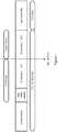
- FIG 1 depicts a communication system, such as a OFDM system or a WCDMA system, including a Radio Access Network (RAN), such as the evolved UMTS Terrestrial Radio Access Network (E-UTRAN) architecture, comprising at least one Radio Base Station (RBS) (or Node B) 15a-b, connected to one or more Radio Network Controllers (RNCs) 10 (only one shown in Figure 2 ).
- the RAN is connected over an interface such as the lu-interface to a Core network (CN) 12, which may be a connection-oriented external CN such as the Public Switched Telephone Network (PSTN) or the Integrated Services Digital Network (ISDN), and/or a connectionless external CN as the Internet.
- CN Core network
- PSTN Public Switched Telephone Network
- ISDN Integrated Services Digital Network
- the RAN and the CN 12 provide communication and control for a plurality of user equipments (UE) 18a-d.
- the UEs 18 each uses downlink (DL) channels (i.e. base-to-user or forward) and uplink (UL) channels (i.e. user-to-base or reverse) to communicate with at least one RBS 15 over a radio or air interface.
- DL downlink
- UL uplink
- the communication system is herein described as a WCDMA communication system.
- the skilled person realizes that the inventive method and arrangement works very well on all communications system.
- the user equipments 18 may be mobile stations such as mobile telephones ("cellular" telephones) and laptops with mobile termination and thus may be, for example, portable, pocket, hand-held, computer-included or car-mounted mobile devices which communicate voice and/or data with the RAN.
- the downlink radio problem detection shall be based on monitoring quality metrics on the downlink signals. Radio problem detection can be declared when one or several of the quality metrics exceed or fall below one or several thresholds within predefined time intervals.
- the set of error events to be used may be UE specific or specific to a group of UEs.
- the specific combination of parameters and different weights to be used for each of the physical channel may be signaled by the eNodeB to the UE e.g. dependent on the type of traffic and the traffic load.
- the conditions to be used are semi-static whereby the set of parameters to be used and the weightings are signaled via higher layer signaling.
- a number of standard combinations are defined such that the eNodeB may signal a reference to such standard combination. This will reduce the number of bits that needs to be transmitted.
- the UE has a number of pre-defined alternative combinations set by a standard to apply dependent on the reception mode that is used, e.g. one specific combination for DRX mode etc.
- the potential candidates for downlink radio quality detection can be:
- Radio link detection algorithm based on combined channels
- Figure 3 is a flow chart, illustrating a method in accordance with an aspect of the invention.
- step 100 the user equipment determines which of said downlink (DL) physical signals and channels are available.
- step 110 the user equipment dynamically selects a subset of said downlink physical signals and channels based on the result of determining in step 100 which of said downlink physical signals and channels are available.
- step 120 the user equipment detects whether there are radio link problems using the selected subset of said downlink physical signals and channels. The details of this determination are set out below. If so, in step 130, the user equipment reports the radio link problems to the radio base station but, if not, the process returns to step 100.
- the error event for a particular channel would depend upon the type of channel. For instance it can be declared when the quality of a channel goes below the desired threshold (SNR, BER etc) or if CRC failure occurs.
- the error event detection is based on mainly single measurement sample of a particular channel, e.g. SCH SNR measured over a single OFDMA symbol or PBCH CRC failure over a single transport block etc.
- the condition for defining an error event for each channel can be set one or more of the following ways: configured by the network, a standardized value, based on UE implementation or combination thereof.
- the aggregate number is obtained by defining a suitable function.
- a general formula is expressed in (1): F ⁇ 1 N error _ event ch _ 1 , ⁇ 2 N error _ event ch _ 2 , ⁇ ⁇ M N error _ event ch _ M ⁇ K 1
- a special case of (1) could be expressed in terms of the weighted linear sum of the error events of all physical channels, i.e. expressed by (2): ⁇ 1 N error _ event ch _ 1 + ⁇ 2 N error _ event ch _ 2 + ⁇ + ⁇ M N error _ event ch _ M ⁇ K 1
- This approach gives UE some flexibility in acquiring sufficient number of measurement samples in shortest possible time.
- the UE could measure only reference symbol BER for radio link detection.
- it can measure SCH BER (or SNR) and reference symbol BER.
- SCH BER or SNR
- reference symbol BER or SNR
- PBCH CRC reference symbol BER
- a problematic radio link may also recover.
- UE should also be able to detect this recovery or improvement.
- the correct events are also obtained from multiple channels depending upon their availability, the UE measurement capability, DRX cycle etc. F ⁇ 1 N correct _ event ch _ 1 , ⁇ 2 N correct _ event ch _ 2 , ⁇ , ⁇ M N correct _ event ch _ M ⁇ K 2
- a special case of (4) could be expressed in terms of the weighted linear sum of the correct events of all physical channels, i.e. expressed by (5): ⁇ 1 N correct _ event ch _ 1 + ⁇ 2 N correct _ event ch _ 2 + ⁇ + ⁇ M N correct _ event ch _ M ⁇ K 2
- Radio link detection algorithm based on timing uncertainty
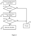
- FIG. 4 is a flowchart, illustrating an alternative method in accordance with the invention.
- the user equipment attempts to estimate the channel on the pilot channel and in step 210 it determines whether this attempt was successful. If the user equipment is unable to properly estimate the channel on the pilot channel to within a predetermined threshold over a predetermined time period, the process passes to step 220, in which the user equipment attemps to detect a timing of transmissions on the synchronization channels. In step 230 it determines whether this attempt was successful. If the user equipment is unable to detect the timing of transmissions on the synchronization channels within a predetermined threshold over a predetermined time period, the process passes to step 240, and the user equipment determines that there is a radio link problem. If the user equipment is able to detect the timing correctly, either at step 210 or step 230, the process can pass to step 250, and proceed normally.
- the radio link can be regarded as problematic if UE is unable to detect the timing (e.g. frame boundary) with certain precision (e.g. with timing accuracy of ⁇ T 0 ⁇ s) over a certain time period or after certain number of successive synchronization attempts.
- the timing can be lost due to bad radio link.
- Another reason could be the drift at the base station transmit timing.
- the timing uncertainty needs to be re-checked by again performing the correlation over the serving SCH channel (more specifically the Primary SCH as it gives frame timing) at regular intervals or when quality of any other channel deteriorates.
- the radio link could be considered bad if the output of correlation (e.g. SNR) stays below certain threshold over an uncertainly range (e.g. ⁇ T 0 ⁇ s).
- the evaluation process should not be too complex since UE already knows the SCH sequences (i.e. P-SCH and S-SCH) of the serving cell and it often checks the timing of the cell.
- a minimum period for evaluating radio link detection could be useful to prevent the affect of fast fading. For instance the output of the correlation detector may occasionally lead to unexpected pessimistic results due to fading.
- a problematic radio link may also recover.
- UE should also be able to detect this recovering. This could also be traced if UE is able to detect the frame timing by performing correlation over the SCH.
- radio link could be regarded as suitable if UE is able to recover the timing within certain accuracy (e.g. ⁇ T 0 ⁇ s).
- a third method could be based on the combination of methods based on combined channels and timing uncertainty described in the foregoing. They can either be carried out in parallel or in tandem.
- the radio link can be considered bad if at least one of the conditions is fulfilled. In another embodiment both conditions have to be fulfilled before the radio link is considered bad.
Description
- The present invention relates to detection of downlink radio link problems.
- Radio link monitoring is vital to maintain radio connections in cellular systems. By regularly reporting the radio conditions to the system different types of actions can be taken when radio link failure occur.
- In UTRA, the physical layers estimate the quality of the radio links and reports on radio frame basis to higher layers the synchronization status via so called synchronization primitives, as described at 3GPP TS 25.214 V7.4.0 "Physical layer procedures (FDD)".
- Reporting radio link quality status will also be needed in E-UTRA, in which a fast and reliable detection of radio problems would be beneficial in order to avoid unnecessary interference in uplink, waste of resources in downlink and unnecessarily long delays before cell reselection or handover can take place.
- The handling of radio link failure in E-UTRA is described in 3GPP TS 36.300 V8.1.0 "Overall description; stage 2" and consists of two phases as illustrated in
Figure 1 , briefly described as - First phase:
- It is started upon radio problem detection which may lead to radio link failure detection after e.g. that a timer period has expired (T1)
- Network based mobility handling
- Second Phase:
- It is started upon radio link failure detection which may lead to RRC state transition from CONNECTED to IDLE after timer (T2)
- UE-based mobility handling
- The judgment of "radio problem detection", as well as procedures for its reporting, is handled by the physical layer. The analogy with UTRA refers to the use of the synchronization primitives, e.g. the "out-of-sync" handling, which is further discussed below.
- In UTRA, fast transmit power control (TPC) is crucial for the system to operate properly. In downlink for example, TPC commands are sent continuously or periodically via the physical control channel (F-)DPCH or DPCCH. The UE measures the quality of this physical control channel over a pre-specified time interval and if the quality is below a specified threshold, the UE reports "out-of-sync" to the network. Error detection through cyclic redundancy check (CRC) is provided to transport blocks mapped to DPDCH. In addition to monitoring the control channel quality, the UE also monitors the number of consecutive CRC failures and if it is above a pre-specified number the UE reports out-of-synch to the network.
- E-UTRA is a pure packet data designed cellular system, in which transmissions of user data in uplink and downlink always take place via shared channels. Orthogonal Frequency Division Multiple (OFDM) technology is used in the downlink, whereas DFT based pre-coded OFDM is used in uplink. As similar to HSPA in UTRA, the UE monitors physical downlink control channels (PDCCH) in order to access UE dedicated user data on the physical downlink shared channel (PDSCH) and the network assign uplink scheduling grants to the UE on demand basis for uplink transmission via the physical uplink control channel (PUCCH) and the physical uplink shared channel (PUSCH). Error detection is provided on transport blocks and control payloads through CRC, and HARQ operations ensure efficient re-transmissions.
- In E-UTRA, no downlink transmit power control (TPC) has been specified and uplink TPC commands are embedded in the control payload mapped to PDCCH, which are sent occasionally by the E-UTRA base station (eNodeB). Thus, no continuous or periodic dedicated physical channels such as (F-)DPCH and DPCCH are present as in UTRA.
- The physical layer signals and channels in E-UTRA downlink are:
- Physical layer signals, i.e. reference signal (pilots) and synchronization signals
- Physical broadcast channel (PBCH)
- PDCCH and PDSCH
- Physical control format indicator channel (PCFICH)
- Physical HARQ indicator channel (PHICH)
- Following observations can be done:
- Physical layer signals and PBCH are transmitted periodically
- Error detection via CRC of transport blocks mapped to PBCH and PDSCH, and of control data mapped to PDCCH
- Some uplink transmissions shall result in downlink responses through the physical channels PDCCH and PHICH
- An advantage of considering periodically transmitted signals and channels that is that the reporting instants of radio problem detection to higher layers then can be known in advance. Using shared channels for monitoring the radio link quality in E-UTRA may lead to an unpredictable reporting delay due to absence of scheduled data.
- For E-UTRA downlink operations, it seems natural to characterize radio problem detection as a UE not able to detect PDCCH and/or PDSCH under a certain time period. Besides not being able to receive any user data, consecutive CRC failures of the control data would also imply that the UE cannot receive any uplink scheduling grants as well as not respond to uplink TPC and time alignment (TA) commands, which are vital for the system to operate properly.
- However, for the PDCCH the UE ID is implicitly encoded into the CRC which implies that a CRC failure may not be due to bad radio link conditions, i.e. the packet was aimed for another UE. For that reasoning, judge radio problem detection on e.g. high number of consecutive CRC failures of control data mapped to PDCCH appears to be less useful.
- Checking the CRC of transport blocks mapped to PDSCH could be one possibility to monitor radio problem detection. Although demodulation of PDSCH requires that the associated PDCCH was correctly detected, the PDCCH should be significantly more robust than PDSCH. In this case, the rate adaptation has resulted in lowest possible user data bit rates but still the UE responds with consecutive NACKs to eNodeB. However, a potential drawback to base radio problem detection only on e.g. a high number of consecutive CRC failures of transport blocks of PDSCH is that the absence of scheduled data will lead to an unpredictable and possibly very long reporting delay.
- In E-UTRA, the common reference signals are sent periodically and are distributed over the whole system bandwidth. Monitoring some quality metric such as e.g. SIR or pilot symbol error rates of the reference signals and report radio problem detection when quality metric is above a certain threshold could be an alternative or an addition to the above PDSCH CRC checks. However, bad quality of the common reference signals does not necessarily reflect the perceived quality of downlink physical channels PDCCH and PDSCH. Additionally, a quality metric can also be associated with synchronization signals such as e.g. the correlations between receive synchronization signal and considered primary synchronization signal are below a certain threshold.
- Error detection through CRC is also provided on transport blocks mapped to the PBCH, which (in contrast to transport blocks mapped to the shared channels) are sent periodically and thus will have a predictable reporting delay. Thus, consecutive failures to read the physical broadcast channel could be used for indicating radio problem detection. However, the quality of the common physical channel PBCH does not necessarily reflect the perceived quality of PDCCH and PDSCH.
- The eNodeB will regularly, but not necessarily periodically, transmit uplink TPC commands that are addressed to a group of UEs. If a UE that belongs to a certain group has not detected such commands within a specified time interval, it could report radio problem detection to higher layers. The same concept is also applicable to other control formats that e.g. include time alignment commands, although these commands are sent in-band and are sent less frequently than the e.g. uplink TPC commands.
- The eNodeB will regularly, but not necessarily periodically, transmit PCFICH which contains information on how many consecutive OFDM symbols of PDCCH that are sent within a sub-frame. There will be three known sequences of 32 bits sent via PCFICH to indicate either 1, or 2 or 3 OFDM symbols. As a quality metric of PCFICH, a UE can evaluate bit errors of the received sequences during a certain time interval and report radio problem detection when high number of consecutive bit errors exceeds a certain threshold.
- The E-UTRA downlink also allows the possibility of discontinuous reception (DRX) in RRC_CONNECTED mode (or LTE_ACTIVE mode as commonly called). This permits UE to save its battery while stay connected since it would be required to wake up only at periodic instances according to the DRX cycle. The network can configure a DRX cycle between 2 ms and up to 2.56 seconds depending upon the type of service e.g. typically 2 or 4 ms for real time services such as voice over IP and 1.28 seconds for non-real time services such as browsing the Internet. During DRX the UE may temporarily go into continuous reception mode when the network is sending data. After the data reception the UE reverts to the normal DRX mode after a timeout configured by the network.
- The UE will try to stay inactive as much as possible during the silent periods of the DRX cycle to achieve maximum possible saving of its battery. But this also implies that UE will mainly perform measurements at the wake up instances for mobility, radio link problem detection (out-of-sync detection, in-sync detection) etc. Due to insufficient measurement opportunities in DRX mode (depending upon the DRX cycle) the UE would be unable to promptly detect the radio link problem.
- It is likely that a very large number of UE are kept in DRX mode. Secondly in DRX mode the network for transmitting data can abruptly switch the UE into continuous reception mode. The UE should therefore stay well connected in terms of radio link quality and so any radio link problem should be reported to the network promptly. Thus, the radio link problem detection should be designed to work effectively in both DRX and non DRX modes of operations.
- The document
WO 2006/086359 A shows methods to detect radio link failure. - One of the problems to be solved by the invention is thus to enable the UE to obtain an adequate number of measurement samples needed for radio problem detection.
- One possibility would be to use a plurality of physical channels for the detection of radio link problem. This approach is particularly attractive in E-UTRA where due to packet mode transmission and frequent use of DRX mode the sampling of multiple physical channels could more easily and quickly enable the UE to obtain adequate number of samples needed for radio link detection.
- The concept of using combined channels (e.g. SCH, BCH, shared channel and pilot channels) has been proposed earlier. However, in the previously proposed methodology the idea is that two or more combination of these channels is always used by the UE for radio link detection. However, due to packet mode and especially due to DRX it may not always be possible for the UE to sample any combination of the channels all the time.
- The invention is defined by the independent claims.
- The basic idea according to the invention is to use a combination of several physical channels for radio link detection where the sub-set of the channels used by the UE are adjusted dynamically depending upon which channels are available at a particular measurement instance. The smallest sub-set would comprise of at least one physical channel. This method would speed up the detection of radio link problems especially in DRX. Thus, the invention provides a possibility to use different combinations of several physical channels and different weights on each of the physical channel for detection of radio link problems. The condition for defining an error event for each channel can be set one or more of the following ways: configured by the network, a standardized value, based on UE implementation or combination thereof.
- The invention provides
- Fast and reliable radio problem detection in downlink despite the lack of downlink dedicated channel due to packet mode transmission.
- Reduced interference in uplink since when the UE notes detection of radio problem, it will e.g. stop transmitting measuring reports or other data in the uplink.
- Limited waste of resources in downlink. Provided the base station receives information on bad downlink radio link it can remove the UE from the scheduling list.
- Shorter handover delay. Provided the base station receives information on bad downlink radio link, serving base station may be altered more quickly if downlink problems are identified rapidly.
- Fast detection of radio link problem in DRX operation and in scenario with limited measurement opportunities
-
-
Figure 1 illustrates radio link failure handling in E-UTRA. -
Figure 2 shows an example of a communication network architecture. -
Figure 3 is a flow chart, illustrating a method in accordance with a first aspect of the present invention. -
Figure 4 is a flow chart, illustrating a method in accordance with a second aspect of the present invention. -
Figure 1 depicts a communication system, such as a OFDM system or a WCDMA system, including a Radio Access Network (RAN), such as the evolved UMTS Terrestrial Radio Access Network (E-UTRAN) architecture, comprising at least one Radio Base Station (RBS) (orNode B) 15a-b, connected to one or more Radio Network Controllers (RNCs) 10 (only one shown inFigure 2 ). The RAN is connected over an interface such as the lu-interface to a Core network (CN) 12, which may be a connection-oriented external CN such as the Public Switched Telephone Network (PSTN) or the Integrated Services Digital Network (ISDN), and/or a connectionless external CN as the Internet. - The RAN and the CN 12 provide communication and control for a plurality of user equipments (UE) 18a-d. The UEs 18 each uses downlink (DL) channels (i.e. base-to-user or forward) and uplink (UL) channels (i.e. user-to-base or reverse) to communicate with at least one RBS 15 over a radio or air interface.
- According to a preferred embodiment of the present invention, the communication system is herein described as a WCDMA communication system. The skilled person, however, realizes that the inventive method and arrangement works very well on all communications system. The user equipments 18 may be mobile stations such as mobile telephones ("cellular" telephones) and laptops with mobile termination and thus may be, for example, portable, pocket, hand-held, computer-included or car-mounted mobile devices which communicate voice and/or data with the RAN.
- In the preferred embodiment the downlink radio problem detection shall be based on monitoring quality metrics on the downlink signals. Radio problem detection can be declared when one or several of the quality metrics exceed or fall below one or several thresholds within predefined time intervals. The set of error events to be used may be UE specific or specific to a group of UEs. The specific combination of parameters and different weights to be used for each of the physical channel may be signaled by the eNodeB to the UE e.g. dependent on the type of traffic and the traffic load. In one embodiment the conditions to be used are semi-static whereby the set of parameters to be used and the weightings are signaled via higher layer signaling. Alternatively a number of standard combinations are defined such that the eNodeB may signal a reference to such standard combination. This will reduce the number of bits that needs to be transmitted. In yet another embodiment, the UE has a number of pre-defined alternative combinations set by a standard to apply dependent on the reception mode that is used, e.g. one specific combination for DRX mode etc.
- The potential candidates for downlink radio quality detection can be:
- Monitoring a downlink reference signal quality metric
∘ E.g., the downlink reference signal quality metric can be the received SIR, or pilot symbol error rate, of the reference signals transmitted depending on the antenna configuration, e.g. reference signals 0 in case of one eNodeB antenna port. - Monitoring a synchronization signal quality metric
∘ E.g., the quality metric can be correlation values between received signals and considered primary synchronization signal. - Monitoring a PBCH quality metric
∘ E.g., the PBCH quality metric can be the number of consecutive PBCH CRC failures - Monitoring a PDSCH quality metric
∘ E.g., the PDSCH quality metric can be the number of consecutive PDSCH CRC failures or the number of cases where the number of HARQ retransmissions exceeds the targeted number of HARQ retransmissions. - Monitoring a time between correct detected PDCCH data referring to E-UTRA control format with TPC commands to multiple users
∘ E.g., the PDCCH quality metric can be the number of absent received radio frames - Monitoring a PCFICH quality metric
∘ E.g., the PCFICH quality metric can be bit errors or quality of soft values. - Monitoring PHICH channel
∘ E.g., the PHICH quality metric can be the quality of the soft bits -
Figure 3 is a flow chart, illustrating a method in accordance with an aspect of the invention. - In
step 100, the user equipment determines which of said downlink (DL) physical signals and channels are available. Instep 110, the user equipment dynamically selects a subset of said downlink physical signals and channels based on the result of determining instep 100 which of said downlink physical signals and channels are available. Instep 120, the user equipment detects whether there are radio link problems using the selected subset of said downlink physical signals and channels. The details of this determination are set out below. If so, instep 130, the user equipment reports the radio link problems to the radio base station but, if not, the process returns to step 100. - As stated above it may not always be possible for the UE due to DRX or lack of scheduling to obtain sufficient number of measurement samples in a stipulated time for detecting radio link problem. But to expedite the detection process several physical channels can be sampled in a dynamic fashion as described below:
Let's assume there are M physical channels (e.g. PBCH, PDSCH, SCH etc), which can potentially be used by the UE for the detection of radio link problems. Then the radio link failure condition is detected if at least X% (0≤X≤100) of the aggregate number of consecutive measurement events (or samples) of different physical channels are erroneous and exceeds or becomes equal to certain threshold (K1). - The error event for a particular channel would depend upon the type of channel. For instance it can be declared when the quality of a channel goes below the desired threshold (SNR, BER etc) or if CRC failure occurs. Secondly the error event detection is based on mainly single measurement sample of a particular channel, e.g. SCH SNR measured over a single OFDMA symbol or PBCH CRC failure over a single transport block etc. The condition for defining an error event for each channel can be set one or more of the following ways: configured by the network, a standardized value, based on UE implementation or combination thereof.
- The aggregate number is obtained by defining a suitable function. A general formula is expressed in (1):

- A special case of (1) could be expressed in terms of the weighted linear sum of the error events of all physical channels, i.e. expressed by (2):

- In case of equal weight for each i.e. if α 1 = α 2 = ··· = αM = 1, then (3) is obtained:

- This approach gives UE some flexibility in acquiring sufficient number of measurement samples in shortest possible time. During wake up instances of the DRX cycle, at one occasion the UE could measure only reference symbol BER for radio link detection. At another instance it can measure SCH BER (or SNR) and reference symbol BER. Similarly at another instance it can check the PBCH CRC and so on. This type of limitation stems from the fact that UE also has to perform regular neighbor cell identification and measurements. The limited measurement capability coupled with the DRX operation put further restraints on the UE in terms of sampling more often and more channels from the serving cell for detecting radio link problem.
- However the situation may also happen when UE is able to measure several physical channels simultaneously in a very short time. But this type of detection should not be performed over too short period. Thus a minimum time period could also be specified over which the detection should be performed even if the aggregated number of error events exceed the limit (K1) expressed in (1).
- A problematic radio link may also recover. Thus, UE should also be able to detect this recovery or improvement. In this case at least there should be sufficient number of correct events exceeding certain threshold (K2) as expressed in (4). The correct events are also obtained from multiple channels depending upon their availability, the UE measurement capability, DRX cycle etc.

- A special case of (4) could be expressed in terms of the weighted linear sum of the correct events of all physical channels, i.e. expressed by (5):

-
Figure 4 is a flowchart, illustrating an alternative method in accordance with the invention. Instep 200, the user equipment attempts to estimate the channel on the pilot channel and instep 210 it determines whether this attempt was successful. If the user equipment is unable to properly estimate the channel on the pilot channel to within a predetermined threshold over a predetermined time period, the process passes to step 220, in which the user equipment attemps to detect a timing of transmissions on the synchronization channels. Instep 230 it determines whether this attempt was successful. If the user equipment is unable to detect the timing of transmissions on the synchronization channels within a predetermined threshold over a predetermined time period, the process passes to step 240, and the user equipment determines that there is a radio link problem. If the user equipment is able to detect the timing correctly, either atstep 210 or step 230, the process can pass to step 250, and proceed normally. - Thus, the radio link can be regarded as problematic if UE is unable to detect the timing (e.g. frame boundary) with certain precision (e.g. with timing accuracy of ± T0 µs) over a certain time period or after certain number of successive synchronization attempts. The timing can be lost due to bad radio link. Another reason could be the drift at the base station transmit timing. Thus, the timing uncertainty needs to be re-checked by again performing the correlation over the serving SCH channel (more specifically the Primary SCH as it gives frame timing) at regular intervals or when quality of any other channel deteriorates. The radio link could be considered bad if the output of correlation (e.g. SNR) stays below certain threshold over an uncertainly range (e.g. ± T0 µs). The evaluation process should not be too complex since UE already knows the SCH sequences (i.e. P-SCH and S-SCH) of the serving cell and it often checks the timing of the cell. A minimum period for evaluating radio link detection could be useful to prevent the affect of fast fading. For instance the output of the correlation detector may occasionally lead to unexpected pessimistic results due to fading.
- A problematic radio link may also recover. Thus, UE should also be able to detect this recovering. This could also be traced if UE is able to detect the frame timing by performing correlation over the SCH. Thus, radio link could be regarded as suitable if UE is able to recover the timing within certain accuracy (e.g. ± T0 µs).
- A third method could be based on the combination of methods based on combined channels and timing uncertainty described in the foregoing. They can either be carried out in parallel or in tandem. In one embodiment the radio link can be considered bad if at least one of the conditions is fulfilled. In another embodiment both conditions have to be fulfilled before the radio link is considered bad.
Claims (13)
- A method, for use in a user equipment in a cellular telecommunication system having a plurality of downlink physical channels, the method comprising:detecting radio link problems using a subset of several of said physical channels, by detecting a radio link problem when a number of error events aggregated using a combination of the several physical channels in said subset exceeds a threshold, andwherein said subset is dynamically adjustable depending upon which channels are available at a particular instant.
- A method as claimed in claim 1, wherein the number of error events comprises a sum of a number of error events using the combination of the several physical channels said subset of said physical channels.
- A method as claimed in claim 2, wherein said sum of the number of error events is a weighted linear sum.
- A method as claimed in claim 2, comprising detecting an error event on a channel when a quality of the channel falls below a threshold value.
- A method as claimed in claim 4, wherein said quality is measured over a symbol.
- A method as claimed in claim 2, comprising detecting an error event on a channel when a CRC failure occurs.
- A method as claimed in any preceding claim, further comprising:
detecting a radio link improvement using said subset. - A method as claimed in claim 7, comprising:
detecting a radio link improvement when an aggregate number of correct events on said subset of said physical channels exceeds a threshold. - A method as claimed in claim 8, wherein the aggregate number of correct events comprises a sum of a number of correct events on said subset of said physical channels.
- A method as claimed in claim 9, wherein said sum of the number of correct events is a weighted linear sum.
- A method as claimed in claim 1, wherein the cellular telecommunication system further has a plurality of downlink physical signals, the method further comprising:determining which of said downlink physical signals and channels are available;dynamically selecting a subset of several of said downlink physical signals and channels based on determining which of said downlink physical signals and channels are available at a given time; anddetecting radio link problems using the selected subset of said downlink physical signals and channels by detecting a radio link problem when a sum of a number of error events using a combination of the several physical signals, channels, or both in the subset exceeds a threshold.
- A method as claimed in claim 11, wherein said sum of the number of error events is a weighted sum.
- A user equipment, for use in a cellular telecommunication system having a plurality of downlink physical signals and channels, the user equipment being adapted to:determine which of said downlink physical signals and channels are available;dynamically select a subset of several of said downlink physical signals and channels based on determining which of said downlink physical signals and channels are available; anddetect radio link problems using the selected subset, by detecting a radio link problem when a sum of a number of error events using a combination of the several physical signals, channels, or both in the subset exceeds a threshold.
Applications Claiming Priority (3)
| Application Number | Priority Date | Filing Date | Title |
|---|---|---|---|
| US97688507P | 2007-10-02 | 2007-10-02 | |
| EP08749282.3A EP2193622B1 (en) | 2007-10-02 | 2008-04-30 | Method and arrangement in a telecommunication system |
| PCT/EP2008/003535 WO2009043392A1 (en) | 2007-10-02 | 2008-04-30 | Method and arrangement in a telecommunication system |
Related Parent Applications (1)
| Application Number | Title | Priority Date | Filing Date |
|---|---|---|---|
| EP08749282.3A Division EP2193622B1 (en) | 2007-10-02 | 2008-04-30 | Method and arrangement in a telecommunication system |
Publications (2)
| Publication Number | Publication Date |
|---|---|
| EP3249847A1 EP3249847A1 (en) | 2017-11-29 |
| EP3249847B1 true EP3249847B1 (en) | 2020-02-12 |
Family
ID=39816842
Family Applications (2)
| Application Number | Title | Priority Date | Filing Date |
|---|---|---|---|
| EP08749282.3A Not-in-force EP2193622B1 (en) | 2007-10-02 | 2008-04-30 | Method and arrangement in a telecommunication system |
| EP17182173.9A Active EP3249847B1 (en) | 2007-10-02 | 2008-04-30 | Method and arrangement in a telecommunication system |
Family Applications Before (1)
| Application Number | Title | Priority Date | Filing Date |
|---|---|---|---|
| EP08749282.3A Not-in-force EP2193622B1 (en) | 2007-10-02 | 2008-04-30 | Method and arrangement in a telecommunication system |
Country Status (7)
| Country | Link |
|---|---|
| US (1) | US8639241B2 (en) |
| EP (2) | EP2193622B1 (en) |
| JP (1) | JP5296081B2 (en) |
| KR (1) | KR101593707B1 (en) |
| CN (1) | CN101809927B (en) |
| BR (1) | BRPI0817630A2 (en) |
| WO (1) | WO2009043392A1 (en) |
Families Citing this family (10)
| Publication number | Priority date | Publication date | Assignee | Title |
|---|---|---|---|---|
| US8169943B2 (en) * | 2007-04-27 | 2012-05-01 | Telefonaktiebolaget Lm Ericsson (Publ) | Method and a device for saving power in a wireless user terminal |
| EP2241126B1 (en) * | 2008-01-03 | 2016-04-13 | Koninklijke Philips N.V. | Method of exchanging data between a base station and a mobile station. |
| US8787177B2 (en) * | 2008-11-03 | 2014-07-22 | Apple Inc. | Techniques for radio link problem and recovery detection in a wireless communication system |
| WO2010053426A2 (en) * | 2008-11-10 | 2010-05-14 | Telefonaktiebolaget L M Ericsson (Publ) | Method and arrangement in a telecommunication system |
| US20110143675A1 (en) * | 2009-06-09 | 2011-06-16 | Qualcomm Incorporated | Method and apparatus for facilitating radio link monitoring and recovery |
| CN103108642B (en) * | 2010-03-24 | 2015-09-23 | 雷克西制药公司 | RNA in skin and fibrotic conditions disturbs |
| US8780782B2 (en) | 2012-03-16 | 2014-07-15 | Qualcomm Incorporated | Method and apparatus for handling radio link failure in LTE eMBMS |
| US9680219B2 (en) * | 2012-05-21 | 2017-06-13 | Qualcomm Incorporated | Antenna switching devices, systems, and methods |
| US20180124697A1 (en) | 2016-10-28 | 2018-05-03 | Alcatel-Lucent Usa Inc. | Verification of cell authenticity in a wireless network using an extended time stamp |
| CN109765558A (en) * | 2019-02-01 | 2019-05-17 | 成都民航空管科技发展有限公司 | Signal methods of comparison and selection, primary processor, auxiliary processor and radar signal ratio select device |
Family Cites Families (7)
| Publication number | Priority date | Publication date | Assignee | Title |
|---|---|---|---|---|
| US5459731A (en) * | 1993-06-24 | 1995-10-17 | National Semiconductor Corporation | Link error monitoring |
| KR100403743B1 (en) * | 2001-04-14 | 2003-10-30 | 삼성전자주식회사 | Apparatus and method for obtaining frame synchronous in mobile communication system |
| US7450943B2 (en) * | 2003-02-12 | 2008-11-11 | Qualcomm Incorporated | Method and apparatus for determining coverage and switching between overlay communication systems |
| US7551597B2 (en) * | 2004-05-06 | 2009-06-23 | Telefonaktiebolaget L M Ericsson (Publ) | Methods and apparatus for fast downlink information of uplink out-of-synchronization |
| US7701844B2 (en) * | 2005-02-09 | 2010-04-20 | Interdigital Technology Corporation | Method and apparatus for recognizing radio link failures associated with HSUPA and HSDPA channels |
| US7826807B2 (en) * | 2005-03-09 | 2010-11-02 | Qualcomm Incorporated | Methods and apparatus for antenna control in a wireless terminal |
| AU2007248806A1 (en) * | 2006-05-05 | 2007-11-15 | Interdigital Technology Corporation | Radio link failure detection procedures in long term evolution uplink and downlink and apparatus therefor |
-
2008
- 2008-04-30 EP EP08749282.3A patent/EP2193622B1/en not_active Not-in-force
- 2008-04-30 WO PCT/EP2008/003535 patent/WO2009043392A1/en active Application Filing
- 2008-04-30 EP EP17182173.9A patent/EP3249847B1/en active Active
- 2008-04-30 BR BRPI0817630 patent/BRPI0817630A2/en not_active Application Discontinuation
- 2008-04-30 US US12/680,272 patent/US8639241B2/en active Active
- 2008-04-30 JP JP2010527333A patent/JP5296081B2/en not_active Expired - Fee Related
- 2008-04-30 KR KR1020107009644A patent/KR101593707B1/en not_active IP Right Cessation
- 2008-04-30 CN CN200880110474.4A patent/CN101809927B/en active Active
Non-Patent Citations (1)
| Title |
|---|
| None * |
Also Published As
| Publication number | Publication date |
|---|---|
| JP5296081B2 (en) | 2013-09-25 |
| WO2009043392A1 (en) | 2009-04-09 |
| CN101809927A (en) | 2010-08-18 |
| BRPI0817630A2 (en) | 2015-04-07 |
| EP3249847A1 (en) | 2017-11-29 |
| EP2193622B1 (en) | 2017-08-02 |
| KR101593707B1 (en) | 2016-02-12 |
| KR20100085080A (en) | 2010-07-28 |
| CN101809927B (en) | 2017-01-18 |
| US8639241B2 (en) | 2014-01-28 |
| EP2193622A1 (en) | 2010-06-09 |
| JP2010541435A (en) | 2010-12-24 |
| US20100311411A1 (en) | 2010-12-09 |
Similar Documents
| Publication | Publication Date | Title |
|---|---|---|
| EP3249847B1 (en) | Method and arrangement in a telecommunication system | |
| EP2314112B1 (en) | Methods for detection of failure and recovery in a radio link | |
| US9775078B2 (en) | Method and apparatus for mitigating data loss during autonomous system information reading | |
| EP3028398B1 (en) | Uplink control information (uci) transmission with bundling considerations | |
| EP1811690B1 (en) | Radio communication system, mobile station, base station, radio communication system control method used for the same, and program of the same | |
| US7995661B2 (en) | Systems and methods for conserving the power supply of a communications device | |
| US8457112B2 (en) | Radio link performance prediction in wireless communication terminal | |
| US6654922B1 (en) | Method and apparatus for declaring correctness of reception of channels for use in a mobile telecommunications system | |
| EP2117136A1 (en) | Base station device and method used in mobile communication system | |
| EP1858177A1 (en) | Wireless communication system | |
| KR101512706B1 (en) | Apparatus and method for providing carrier information | |
| WO2011071789A1 (en) | User admission, power, rate and mobility control method for relay communication systems | |
| WO2011005524A2 (en) | Method and apparatus for network optimization using son solutions | |
| KR101921842B1 (en) | System and method for transmit power control with secondary uplink pilot channel | |
| WO2015139168A1 (en) | Method, device, and equipment for outer loop power control | |
| EP2597836A1 (en) | Method and base station for scheduling control |
Legal Events
| Date | Code | Title | Description |
|---|---|---|---|
| PUAI | Public reference made under article 153(3) epc to a published international application that has entered the european phase |
Free format text: ORIGINAL CODE: 0009012 |
|
| STAA | Information on the status of an ep patent application or granted ep patent |
Free format text: STATUS: REQUEST FOR EXAMINATION WAS MADE |
|
| 17P | Request for examination filed |
Effective date: 20170719 |
|
| AC | Divisional application: reference to earlier application |
Ref document number: 2193622 Country of ref document: EP Kind code of ref document: P |
|
| AK | Designated contracting states |
Kind code of ref document: A1 Designated state(s): AT BE BG CH CY CZ DE DK EE ES FI FR GB GR HR HU IE IS IT LI LT LU LV MC MT NL NO PL PT RO SE SI SK TR |
|
| GRAP | Despatch of communication of intention to grant a patent |
Free format text: ORIGINAL CODE: EPIDOSNIGR1 |
|
| STAA | Information on the status of an ep patent application or granted ep patent |
Free format text: STATUS: GRANT OF PATENT IS INTENDED |
|
| RIC1 | Information provided on ipc code assigned before grant |
Ipc: H04W 36/30 20090101ALI20191122BHEP Ipc: H04L 25/02 20060101ALI20191122BHEP Ipc: H04L 1/20 20060101ALI20191122BHEP Ipc: H04L 1/00 20060101ALI20191122BHEP Ipc: H04W 72/12 20090101ALI20191122BHEP Ipc: H04L 1/18 20060101AFI20191122BHEP |
|
| GRAS | Grant fee paid |
Free format text: ORIGINAL CODE: EPIDOSNIGR3 |
|
| INTG | Intention to grant announced |
Effective date: 20191213 |
|
| GRAA | (expected) grant |
Free format text: ORIGINAL CODE: 0009210 |
|
| STAA | Information on the status of an ep patent application or granted ep patent |
Free format text: STATUS: THE PATENT HAS BEEN GRANTED |
|
| AC | Divisional application: reference to earlier application |
Ref document number: 2193622 Country of ref document: EP Kind code of ref document: P |
|
| AK | Designated contracting states |
Kind code of ref document: B1 Designated state(s): AT BE BG CH CY CZ DE DK EE ES FI FR GB GR HR HU IE IS IT LI LT LU LV MC MT NL NO PL PT RO SE SI SK TR |
|
| REG | Reference to a national code |
Ref country code: GB Ref legal event code: FG4D |
|
| REG | Reference to a national code |
Ref country code: CH Ref legal event code: EP |
|
| REG | Reference to a national code |
Ref country code: AT Ref legal event code: REF Ref document number: 1233508 Country of ref document: AT Kind code of ref document: T Effective date: 20200215 |
|
| REG | Reference to a national code |
Ref country code: IE Ref legal event code: FG4D |
|
| REG | Reference to a national code |
Ref country code: DE Ref legal event code: R096 Ref document number: 602008062145 Country of ref document: DE |
|
| PG25 | Lapsed in a contracting state [announced via postgrant information from national office to epo] |
Ref country code: NO Free format text: LAPSE BECAUSE OF FAILURE TO SUBMIT A TRANSLATION OF THE DESCRIPTION OR TO PAY THE FEE WITHIN THE PRESCRIBED TIME-LIMIT Effective date: 20200512 Ref country code: FI Free format text: LAPSE BECAUSE OF FAILURE TO SUBMIT A TRANSLATION OF THE DESCRIPTION OR TO PAY THE FEE WITHIN THE PRESCRIBED TIME-LIMIT Effective date: 20200212 |
|
| REG | Reference to a national code |
Ref country code: LT Ref legal event code: MG4D |
|
| REG | Reference to a national code |
Ref country code: NL Ref legal event code: MP Effective date: 20200212 |
|
| PG25 | Lapsed in a contracting state [announced via postgrant information from national office to epo] |
Ref country code: LV Free format text: LAPSE BECAUSE OF FAILURE TO SUBMIT A TRANSLATION OF THE DESCRIPTION OR TO PAY THE FEE WITHIN THE PRESCRIBED TIME-LIMIT Effective date: 20200212 Ref country code: SE Free format text: LAPSE BECAUSE OF FAILURE TO SUBMIT A TRANSLATION OF THE DESCRIPTION OR TO PAY THE FEE WITHIN THE PRESCRIBED TIME-LIMIT Effective date: 20200212 Ref country code: HR Free format text: LAPSE BECAUSE OF FAILURE TO SUBMIT A TRANSLATION OF THE DESCRIPTION OR TO PAY THE FEE WITHIN THE PRESCRIBED TIME-LIMIT Effective date: 20200212 Ref country code: BG Free format text: LAPSE BECAUSE OF FAILURE TO SUBMIT A TRANSLATION OF THE DESCRIPTION OR TO PAY THE FEE WITHIN THE PRESCRIBED TIME-LIMIT Effective date: 20200512 Ref country code: IS Free format text: LAPSE BECAUSE OF FAILURE TO SUBMIT A TRANSLATION OF THE DESCRIPTION OR TO PAY THE FEE WITHIN THE PRESCRIBED TIME-LIMIT Effective date: 20200612 Ref country code: GR Free format text: LAPSE BECAUSE OF FAILURE TO SUBMIT A TRANSLATION OF THE DESCRIPTION OR TO PAY THE FEE WITHIN THE PRESCRIBED TIME-LIMIT Effective date: 20200513 |
|
| PG25 | Lapsed in a contracting state [announced via postgrant information from national office to epo] |
Ref country code: NL Free format text: LAPSE BECAUSE OF FAILURE TO SUBMIT A TRANSLATION OF THE DESCRIPTION OR TO PAY THE FEE WITHIN THE PRESCRIBED TIME-LIMIT Effective date: 20200212 |
|
| PG25 | Lapsed in a contracting state [announced via postgrant information from national office to epo] |
Ref country code: SK Free format text: LAPSE BECAUSE OF FAILURE TO SUBMIT A TRANSLATION OF THE DESCRIPTION OR TO PAY THE FEE WITHIN THE PRESCRIBED TIME-LIMIT Effective date: 20200212 Ref country code: RO Free format text: LAPSE BECAUSE OF FAILURE TO SUBMIT A TRANSLATION OF THE DESCRIPTION OR TO PAY THE FEE WITHIN THE PRESCRIBED TIME-LIMIT Effective date: 20200212 Ref country code: CZ Free format text: LAPSE BECAUSE OF FAILURE TO SUBMIT A TRANSLATION OF THE DESCRIPTION OR TO PAY THE FEE WITHIN THE PRESCRIBED TIME-LIMIT Effective date: 20200212 Ref country code: DK Free format text: LAPSE BECAUSE OF FAILURE TO SUBMIT A TRANSLATION OF THE DESCRIPTION OR TO PAY THE FEE WITHIN THE PRESCRIBED TIME-LIMIT Effective date: 20200212 Ref country code: LT Free format text: LAPSE BECAUSE OF FAILURE TO SUBMIT A TRANSLATION OF THE DESCRIPTION OR TO PAY THE FEE WITHIN THE PRESCRIBED TIME-LIMIT Effective date: 20200212 Ref country code: PT Free format text: LAPSE BECAUSE OF FAILURE TO SUBMIT A TRANSLATION OF THE DESCRIPTION OR TO PAY THE FEE WITHIN THE PRESCRIBED TIME-LIMIT Effective date: 20200705 Ref country code: ES Free format text: LAPSE BECAUSE OF FAILURE TO SUBMIT A TRANSLATION OF THE DESCRIPTION OR TO PAY THE FEE WITHIN THE PRESCRIBED TIME-LIMIT Effective date: 20200212 Ref country code: EE Free format text: LAPSE BECAUSE OF FAILURE TO SUBMIT A TRANSLATION OF THE DESCRIPTION OR TO PAY THE FEE WITHIN THE PRESCRIBED TIME-LIMIT Effective date: 20200212 |
|
| REG | Reference to a national code |
Ref country code: DE Ref legal event code: R097 Ref document number: 602008062145 Country of ref document: DE |
|
| REG | Reference to a national code |
Ref country code: AT Ref legal event code: MK05 Ref document number: 1233508 Country of ref document: AT Kind code of ref document: T Effective date: 20200212 |
|
| PG25 | Lapsed in a contracting state [announced via postgrant information from national office to epo] |
Ref country code: MC Free format text: LAPSE BECAUSE OF FAILURE TO SUBMIT A TRANSLATION OF THE DESCRIPTION OR TO PAY THE FEE WITHIN THE PRESCRIBED TIME-LIMIT Effective date: 20200212 |
|
| REG | Reference to a national code |
Ref country code: CH Ref legal event code: PL |
|
| PLBE | No opposition filed within time limit |
Free format text: ORIGINAL CODE: 0009261 |
|
| STAA | Information on the status of an ep patent application or granted ep patent |
Free format text: STATUS: NO OPPOSITION FILED WITHIN TIME LIMIT |
|
| 26N | No opposition filed |
Effective date: 20201113 |
|
| PG25 | Lapsed in a contracting state [announced via postgrant information from national office to epo] |
Ref country code: LU Free format text: LAPSE BECAUSE OF NON-PAYMENT OF DUE FEES Effective date: 20200430 Ref country code: AT Free format text: LAPSE BECAUSE OF FAILURE TO SUBMIT A TRANSLATION OF THE DESCRIPTION OR TO PAY THE FEE WITHIN THE PRESCRIBED TIME-LIMIT Effective date: 20200212 Ref country code: CH Free format text: LAPSE BECAUSE OF NON-PAYMENT OF DUE FEES Effective date: 20200430 Ref country code: LI Free format text: LAPSE BECAUSE OF NON-PAYMENT OF DUE FEES Effective date: 20200430 Ref country code: FR Free format text: LAPSE BECAUSE OF NON-PAYMENT OF DUE FEES Effective date: 20200430 Ref country code: IT Free format text: LAPSE BECAUSE OF FAILURE TO SUBMIT A TRANSLATION OF THE DESCRIPTION OR TO PAY THE FEE WITHIN THE PRESCRIBED TIME-LIMIT Effective date: 20200212 |
|
| REG | Reference to a national code |
Ref country code: BE Ref legal event code: MM Effective date: 20200430 |
|
| PG25 | Lapsed in a contracting state [announced via postgrant information from national office to epo] |
Ref country code: SI Free format text: LAPSE BECAUSE OF FAILURE TO SUBMIT A TRANSLATION OF THE DESCRIPTION OR TO PAY THE FEE WITHIN THE PRESCRIBED TIME-LIMIT Effective date: 20200212 Ref country code: PL Free format text: LAPSE BECAUSE OF FAILURE TO SUBMIT A TRANSLATION OF THE DESCRIPTION OR TO PAY THE FEE WITHIN THE PRESCRIBED TIME-LIMIT Effective date: 20200212 Ref country code: BE Free format text: LAPSE BECAUSE OF NON-PAYMENT OF DUE FEES Effective date: 20200430 |
|
| PG25 | Lapsed in a contracting state [announced via postgrant information from national office to epo] |
Ref country code: IE Free format text: LAPSE BECAUSE OF NON-PAYMENT OF DUE FEES Effective date: 20200430 |
|
| PG25 | Lapsed in a contracting state [announced via postgrant information from national office to epo] |
Ref country code: TR Free format text: LAPSE BECAUSE OF FAILURE TO SUBMIT A TRANSLATION OF THE DESCRIPTION OR TO PAY THE FEE WITHIN THE PRESCRIBED TIME-LIMIT Effective date: 20200212 Ref country code: MT Free format text: LAPSE BECAUSE OF FAILURE TO SUBMIT A TRANSLATION OF THE DESCRIPTION OR TO PAY THE FEE WITHIN THE PRESCRIBED TIME-LIMIT Effective date: 20200212 Ref country code: CY Free format text: LAPSE BECAUSE OF FAILURE TO SUBMIT A TRANSLATION OF THE DESCRIPTION OR TO PAY THE FEE WITHIN THE PRESCRIBED TIME-LIMIT Effective date: 20200212 |
|
| PGFP | Annual fee paid to national office [announced via postgrant information from national office to epo] |
Ref country code: GB Payment date: 20220427 Year of fee payment: 15 Ref country code: DE Payment date: 20220427 Year of fee payment: 15 |
|
| REG | Reference to a national code |
Ref country code: DE Ref legal event code: R119 Ref document number: 602008062145 Country of ref document: DE |
|
| GBPC | Gb: european patent ceased through non-payment of renewal fee |
Effective date: 20230430 |
|
| PG25 | Lapsed in a contracting state [announced via postgrant information from national office to epo] |
Ref country code: GB Free format text: LAPSE BECAUSE OF NON-PAYMENT OF DUE FEES Effective date: 20230430 |
|
| PG25 | Lapsed in a contracting state [announced via postgrant information from national office to epo] |
Ref country code: GB Free format text: LAPSE BECAUSE OF NON-PAYMENT OF DUE FEES Effective date: 20230430 Ref country code: DE Free format text: LAPSE BECAUSE OF NON-PAYMENT OF DUE FEES Effective date: 20231103 |