EP3249761A1 - Terminal bending tool - Google Patents
Terminal bending tool Download PDFInfo
- Publication number
- EP3249761A1 EP3249761A1 EP17172171.5A EP17172171A EP3249761A1 EP 3249761 A1 EP3249761 A1 EP 3249761A1 EP 17172171 A EP17172171 A EP 17172171A EP 3249761 A1 EP3249761 A1 EP 3249761A1
- Authority
- EP
- European Patent Office
- Prior art keywords
- terminal
- bending tool
- terminals
- plate part
- terminal bending
- Prior art date
- Legal status (The legal status is an assumption and is not a legal conclusion. Google has not performed a legal analysis and makes no representation as to the accuracy of the status listed.)
- Withdrawn
Links
Images




Classifications
-
- H—ELECTRICITY
- H01—ELECTRIC ELEMENTS
- H01R—ELECTRICALLY-CONDUCTIVE CONNECTIONS; STRUCTURAL ASSOCIATIONS OF A PLURALITY OF MUTUALLY-INSULATED ELECTRICAL CONNECTING ELEMENTS; COUPLING DEVICES; CURRENT COLLECTORS
- H01R43/00—Apparatus or processes specially adapted for manufacturing, assembling, maintaining, or repairing of line connectors or current collectors or for joining electric conductors
- H01R43/16—Apparatus or processes specially adapted for manufacturing, assembling, maintaining, or repairing of line connectors or current collectors or for joining electric conductors for manufacturing contact members, e.g. by punching and by bending
-
- H—ELECTRICITY
- H01—ELECTRIC ELEMENTS
- H01R—ELECTRICALLY-CONDUCTIVE CONNECTIONS; STRUCTURAL ASSOCIATIONS OF A PLURALITY OF MUTUALLY-INSULATED ELECTRICAL CONNECTING ELEMENTS; COUPLING DEVICES; CURRENT COLLECTORS
- H01R43/00—Apparatus or processes specially adapted for manufacturing, assembling, maintaining, or repairing of line connectors or current collectors or for joining electric conductors
- H01R43/04—Apparatus or processes specially adapted for manufacturing, assembling, maintaining, or repairing of line connectors or current collectors or for joining electric conductors for forming connections by deformation, e.g. crimping tool
-
- B—PERFORMING OPERATIONS; TRANSPORTING
- B21—MECHANICAL METAL-WORKING WITHOUT ESSENTIALLY REMOVING MATERIAL; PUNCHING METAL
- B21D—WORKING OR PROCESSING OF SHEET METAL OR METAL TUBES, RODS OR PROFILES WITHOUT ESSENTIALLY REMOVING MATERIAL; PUNCHING METAL
- B21D7/00—Bending rods, profiles, or tubes
- B21D7/02—Bending rods, profiles, or tubes over a stationary forming member; by use of a swinging forming member or abutment
- B21D7/024—Bending rods, profiles, or tubes over a stationary forming member; by use of a swinging forming member or abutment by a swinging forming member
-
- H—ELECTRICITY
- H01—ELECTRIC ELEMENTS
- H01R—ELECTRICALLY-CONDUCTIVE CONNECTIONS; STRUCTURAL ASSOCIATIONS OF A PLURALITY OF MUTUALLY-INSULATED ELECTRICAL CONNECTING ELEMENTS; COUPLING DEVICES; CURRENT COLLECTORS
- H01R12/00—Structural associations of a plurality of mutually-insulated electrical connecting elements, specially adapted for printed circuits, e.g. printed circuit boards [PCB], flat or ribbon cables, or like generally planar structures, e.g. terminal strips, terminal blocks; Coupling devices specially adapted for printed circuits, flat or ribbon cables, or like generally planar structures; Terminals specially adapted for contact with, or insertion into, printed circuits, flat or ribbon cables, or like generally planar structures
- H01R12/70—Coupling devices
- H01R12/71—Coupling devices for rigid printing circuits or like structures
- H01R12/72—Coupling devices for rigid printing circuits or like structures coupling with the edge of the rigid printed circuits or like structures
- H01R12/722—Coupling devices for rigid printing circuits or like structures coupling with the edge of the rigid printed circuits or like structures coupling devices mounted on the edge of the printed circuits
- H01R12/724—Coupling devices for rigid printing circuits or like structures coupling with the edge of the rigid printed circuits or like structures coupling devices mounted on the edge of the printed circuits containing contact members forming a right angle
Definitions
- the present disclosure relates to a terminal bending tool, more particularly, to a terminal bending tool adapted to bend a row of terminals simultaneously.
- the present disclosure is intended to overcome at least one aspect of the above-mentioned problems and deficiencies in the prior art.
- a terminal bending tool comprising: a plate part extending in a first horizontal direction; a plurality of receiving grooves formed on the plate part and arranged in a row in the first horizontal direction so that the plate part is in a form of a comb; and a plurality of rollers pivotally mounted in the plurality of receiving grooves respectively, at least one terminal to be bent being adapted to be received and positioned in the receiving grooves and being in physical contact with outer circumferential surfaces of the rollers in the receiving grooves, respectively.
- the terminal bending tool is adapted to simultaneously bend the plurality of terminals which are arranged in a row in the first horizontal direction.
- the number of the plurality of terminals which are arranged in the row in the first horizontal direction is equivalent to or less than the number of the plurality of receiving grooves which are arranged in a row in the first horizontal direction.
- the plurality of rollers are pivotally mounted in respective receiving grooves through a single pivot shaft mounted on the plate part.
- the pivot shaft passes through a mounting hole in the plate part in the first horizontal direction and passes through center mounting holes on the plurality of rollers, such that the plurality of rollers are pivotally mounted in respective receiving grooves.
- the pivot shaft is fixed on the plate part by a positioning pin inserted in the plate part.
- a vertical insertion hole is formed in the plate part and a notch is formed on the outer periphery of the pivot shaft, the positioning pin is inserted into the insertion hole and is held in the notch of the pivot shaft, so that the pivot shaft is fixed on the plate part.
- a first guiding surface which is tilt, is formed on a partition wall at a side facing each receiving groove to guide the terminal to be bent into the receiving groove smoothly.
- a channel is formed between two adjacent receiving grooves and the receiving grooves and the channels are arranged alternatively; the terminals are received in respective receiving grooves, and a partition wall between two adjacent terminal holding grooves is partly received in corresponding channel, during the terminals held in the terminal holding grooves of the connector casing are bent.
- a second guiding surface which is tilt, is formed on the partition wall at the other side facing each receiving groove to guide the partition wall to enter into the corresponding terminal holding channel smoothly.
- each receiving groove comprises a forepart at an edge of the plate part of the terminal bending tool and a bottom part on a bottom of the plate part of the terminal bending tool; the forepart of the receiving groove passes through the plate part in the vertical direction and the roller is mounted on the forepart of the receiving groove; the bottom part of the receiving groove extends a preset length in a second horizontal direction perpendicular to the first horizontal direction and the vertical direction Z.
- a part of the terminal which is to be bent is totally received and positioned in the bottom part of the receiving groove when the terminal is initially bent; a part of the terminal, which has been bent, is received and positioned in the forepart of the receiving groove after the terminal is bent.
- the terminal bent tool further comprises a curved transition part connected with the plate part and a mounting part connected with the curved transition part, such that the terminal bending tool is in a L form as a whole.
- a mounting hole is formed in the mounting part, which is adapted to be mounted on a moving mechanism via a threaded connector passing through the mounting hole.
- the moving mechanism is adapted to drive the terminal bending tool to move in the vertical direction.
- the terminals are pressed by the rollers. Since the roller has a smooth outer circumferential surface, and during the bending, the rollers rotate relative to the surface of the terminals, the surface of the terminal in contact with it will not be scratched, ensuring the surface quality of the folded terminals.
- the terminals are positioned in the corresponding receiving grooves of the terminal bending tool, and there will not be any positional offsets, ensuring the positional accuracy of the folded terminals.
- a row of terminals may be simultaneously bent using the terminal bending tool, improving the bending efficiency.
- a terminal bending tool comprising: a plate part extending in a first horizontal direction; a plurality of receiving grooves formed on the plate part and arranged in a row in the first horizontal direction so that the plate part is in a form of a comb; and a plurality of rollers which are pivotally mounted in the plurality of receiving grooves respectively.
- At least one terminal to be bent is adapted to be received and positioned in the receiving grooves and is in physical contact with outer circumferential surface of the rollers in the receiving grooves, respectively.
- Fig. 1 shows a schematic perspective view of a terminal bending tool 10 according to an exemplary embodiment of the present disclosure
- Fig. 2 shows a partially enlarged schematic view of the terminal bending tool 10 shown in Figure 1
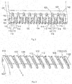
- Fig. 3 shows a bottom view of the terminal bending tool 10 shown in Figure 2
- Fig. 4 shows an exploded view of the terminal bending tool 10 shown in Figure 1 .
- the terminal bending tool 10 comprises a plate part 100 extending in a first horizontal direction X; a plurality of receiving grooves 110 formed on the plate part 100 and arranged in a row in the first horizontal direction X so that the plate part100 is in a form of a comb; and a plurality of rollers 120 which are pivotally mounted in the plurality of receiving grooves1 10 respectively.
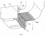
- Fig. 5 shows a schematic view of the terminal bending tool 10 when bending the terminals 21 initially
- Fig. 6 shows a schematic view of the terminal bending tool 10 after finishing bending terminals 21
- Fig. 7 shows a positional relationship between the bent terminals 21 and the terminal bending tool 10.
- the terminals 21 to be bent are adapted to be received and positioned in the receiving grooves 110 and are in physical contact with outer circumferential surfaces of the rollers 120 in the receiving grooves 110, respectively.
- the terminal bending tool 10 is moved in a vertical direction Z perpendicular to the first horizontal direction X
- the terminals 21 received in the receiving grooves 110 are bent under pushing and pressing of the rollers 120, respectively.
- the rollers 120 are rotated, such that the roller 120 is moved in a rolling manner with respect to the surface of the terminal 21.
- the terminals 21 are pressed by the rollers 120. Since the rollers 120 each has a smooth outer circumferential surface, and during bending the terminals 21, the rollers 120 rotate relative to the surfaces of the terminals 21, respectively, the surface of each terminal 120 in contact with the roller will not be scratched, ensuring the surface quality of the folded terminals 21.
- the terminals 21 are positioned in the corresponding receiving grooves 110 of the terminal bending tool 10, and there will not be any positional offsets, ensuring the positional accuracy of the bent terminals.
- the terminal bending tool 10 is adapted to bend a row of terminals 21 simultaneously. In this regard, it improves the bending efficiency.
- the number of the row of terminals 21 is equivalent to the number of the row of receiving grooves110. That is, the row of terminals corresponds to the row of the receiving grooves 110 one by one. However, it is to be noted that the present disclosure is not limited to the illustrated embodiment, and the number of the row of terminals 21 may be less than the number of the row of receiving grooves 110. That is, the terminal bending tool 10 of the present disclosure is adapted to simultaneously bend a row of terminals with a different number. In addition, it is to be noted that the terminal bending tool 10 of the present disclosure is also suitable for bending only a single terminal at a time.
- the plurality of rollers 120 are pivotally mounted in respective receiving grooves 110 through a single pivot shaft 130 mounted on the plate part 100.
- the pivot shaft 130 passes through a mounting hole 101 formed in the plate part 100 in the first horizontal direction X and passes through center mounting holes 121 formed in the plurality of rollers 120 respectively, such that the plurality of rollers 120 are pivotally mounted in respective receiving grooves 110.
- the pivot shaft 130 is mounted on the plate part 100 by a positioning pin 140 inserted in the plate part 100.
- a vertical insertion hole 102 is formed in the plate part 100 and a notch 131 is formed in the outer periphery of the pivot shaft 130, the positioning pin 140 is inserted into the insertion hole 102 and is held in the notch 131 of the pivot shaft 130, thereby fixing the pivot shaft 130 onto the plate part 100.
- a first guiding surface 112 which is tilt, is formed on a partition wall 111 at a side thereof facing each receiving groove 110 to guide the terminal 21 to be bent into the receiving groove 110 smoothly.
- a channel 114 is formed between two adjacent receiving grooves 110, and the channel 114 and the receiving groove 110 are partitioned by the partition wall 111.
- the receiving grooves 110 and the channels 114 are arranged alternatively; the terminals 21 are received in respective receiving grooves 110, and a partition wall 23 between two adjacent terminal holding grooves 22 of the connector casing 20 is partly received in corresponding channel 114, during the terminals 21 are held in the terminal holding grooves 22 of a connector casing 20 are bent.
- a second guiding surface 113 which is tilt, and is formed on the partition wall 111 at the other side thereof facing each receiving groove 110 to guide the partition wall 111 to enter into the corresponding terminal holding channel 22 smoothly.
- each receiving groovel10 comprises a forepart 1101 at an edge of the plate part 100 of the terminal bending tool 10, and a bottom part 1102 on a bottom of the plate part 100 of the terminal bending tool 10.
- the forepart 1101 of the receiving groove 100 passes through the plate part 100 in the vertical direction Z and the roller 120 is mounted on the forepart 1101 of the receiving groove 110.
- the bottom part 1102 of the receiving groove 110 extends a predetermined length in a second horizontal direction Y perpendicular to the first horizontal direction X and the vertical direction Z.
- a part of the terminal 21 which is to be bent is totally received and positioned in the bottom part 1102 of the receiving groove 110 when the terminal 21 is initially bent.
- a part of the terminal 21 which has been bent is received and positioned in the forepart 1101 of the receiving groove 110 after the terminal 21 is bent.
- the terminal bent tool 10 further comprises a curved transition part 200 connected with the plate part 100 and a mounting part 300 connected with the curved transition part 200, such that the terminal bending tool 10 is in a L form as a whole.
- a mounting hole 310 is formed in the mounting part 300, which is adapted to be mounted on a moving mechanism (not shown in the Figures, for example a X-Y-Z three axes translation mechanism) via a threaded connector passing through the mounting hole 310, the moving mechanism being adapted to drive the terminal bending tool 10 to move in the vertical direction Z to bend the terminal 21.
- a moving mechanism not shown in the Figures, for example a X-Y-Z three axes translation mechanism
- Figs. 8A, 8B and 8C show operations of bending terminals 21 by pressing the terminals 21 with rollers 120, in which Fig. 8A shows a schematic view at the beginning of bending, Fig. 8B shows a schematic view during bending, and Fig. 8C shows a schematic view at the end of bending.
Landscapes
- Engineering & Computer Science (AREA)
- Manufacturing & Machinery (AREA)
- Mechanical Engineering (AREA)
- Manufacturing Of Electrical Connectors (AREA)
- Bending Of Plates, Rods, And Pipes (AREA)
Abstract
The present disclosure relates to a terminal bending tools including: a plate part extending in a first horizontal direction; a plurality of receiving grooves formed on the plate part and arranged in a row in the first horizontal direction so that the plate part is in a form of a comb; and a plurality of rollers pivotally mounted in the plurality of receiving grooves respectively. At least one terminal to be bent are adapted to be received and positioned in the receiving grooves and are in physical contact with the outer circumferential surface of the rollers in the receiving grooves, respectively. When the terminal bending tool is moved in a vertical direction perpendicular to the first horizontal direction, the terminals received in the receiving grooves are bent under pressing of the corresponding rollers. During bending the terminals, the rollers are rotated and moved on the surfaces of the terminals, respectively. In addition, the terminals are positioned in the receiving slots to ensure the position accuracy of the terminals. In addition, the terminal bending tool may be used to bend a row of terminals simultaneously, improving the bending efficiency.
Description
- This application claims the benefit of
Chinese Patent Application No. 201620498336.X filed on May 27, 2016 - The present disclosure relates to a terminal bending tool, more particularly, to a terminal bending tool adapted to bend a row of terminals simultaneously.
- During the manufacture of an electrical connector, it is sometime necessary to bend a conductive terminal of the connector by a preset angel, for example 90°. In the prior art, the conductive terminal is bent manually. However, only one conductive terminal may be bent manually one time, and a row of conductive terminals cannot be bent simultaneously. Therefore, the bending efficiency is very limited. In addition, it is difficult to ensure the bending accuracy due to manual operation. There is often a large error in the bended position, degrading the bending accuracy of the conductive terminal, which makes it difficult to mount the conductive terminal which has been bent onto the circuit board correctly. In addition, when bending it manually, a worker needs to clamp the conductive terminal with tools such as pliers, which creates scratches on a surface of the conductive terminals, degrading the quality of the conductive terminals.
- Accordingly, the present disclosure is intended to overcome at least one aspect of the above-mentioned problems and deficiencies in the prior art.
- To achieve above mentioned objection, according to an aspect of the present invention, there is provided a terminal bending tool, comprising: a plate part extending in a first horizontal direction; a plurality of receiving grooves formed on the plate part and arranged in a row in the first horizontal direction so that the plate part is in a form of a comb; and a plurality of rollers pivotally mounted in the plurality of receiving grooves respectively, at least one terminal to be bent being adapted to be received and positioned in the receiving grooves and being in physical contact with outer circumferential surfaces of the rollers in the receiving grooves, respectively. When the terminal bending tool is moved in a vertical direction perpendicular to the first horizontal direction, the terminals received in the corresponding receiving grooves are bent under pressing of the rollers. During pushing and bending the terminals, the rollers are rotated and moved on surfaces of the terminals, respectively.
- According to an exemplary embodiment of the present disclosure, the terminal bending tool is adapted to simultaneously bend the plurality of terminals which are arranged in a row in the first horizontal direction.
- According to another exemplary embodiment of the present disclosure, the number of the plurality of terminals which are arranged in the row in the first horizontal direction is equivalent to or less than the number of the plurality of receiving grooves which are arranged in a row in the first horizontal direction.
- According to another exemplary embodiment of the present disclosure, the plurality of rollers are pivotally mounted in respective receiving grooves through a single pivot shaft mounted on the plate part.
- According to another exemplary embodiment of the present disclosure, the pivot shaft passes through a mounting hole in the plate part in the first horizontal direction and passes through center mounting holes on the plurality of rollers, such that the plurality of rollers are pivotally mounted in respective receiving grooves.
- According to another exemplary embodiment of the present disclosure, the pivot shaft is fixed on the plate part by a positioning pin inserted in the plate part.
- According to another exemplary embodiment of the present disclosure, a vertical insertion hole is formed in the plate part and a notch is formed on the outer periphery of the pivot shaft, the positioning pin is inserted into the insertion hole and is held in the notch of the pivot shaft, so that the pivot shaft is fixed on the plate part.
- According to another exemplary embodiment of the present disclosure, a first guiding surface, which is tilt, is formed on a partition wall at a side facing each receiving groove to guide the terminal to be bent into the receiving groove smoothly.
- According to another exemplary embodiment of the present disclosure, a channel is formed between two adjacent receiving grooves and the receiving grooves and the channels are arranged alternatively; the terminals are received in respective receiving grooves, and a partition wall between two adjacent terminal holding grooves is partly received in corresponding channel, during the terminals held in the terminal holding grooves of the connector casing are bent.
- According to another exemplary embodiment of the present disclosure, a second guiding surface, which is tilt, is formed on the partition wall at the other side facing each receiving groove to guide the partition wall to enter into the corresponding terminal holding channel smoothly.
- According to another exemplary embodiment of the present disclosure, each receiving groove comprises a forepart at an edge of the plate part of the terminal bending tool and a bottom part on a bottom of the plate part of the terminal bending tool; the forepart of the receiving groove passes through the plate part in the vertical direction and the roller is mounted on the forepart of the receiving groove; the bottom part of the receiving groove extends a preset length in a second horizontal direction perpendicular to the first horizontal direction and the vertical direction Z.
- According to another exemplary embodiment of the present disclosure, a part of the terminal which is to be bent is totally received and positioned in the bottom part of the receiving groove when the terminal is initially bent; a part of the terminal, which has been bent, is received and positioned in the forepart of the receiving groove after the terminal is bent.
- According to another exemplary embodiment of the present disclosure, the terminal bent tool further comprises a curved transition part connected with the plate part and a mounting part connected with the curved transition part, such that the terminal bending tool is in a L form as a whole.
- According to another exemplary embodiment of the present disclosure, a mounting hole is formed in the mounting part, which is adapted to be mounted on a moving mechanism via a threaded connector passing through the mounting hole. The moving mechanism is adapted to drive the terminal bending tool to move in the vertical direction.
- In the above mentioned embodiments of the present invention, during the bending, the terminals are pressed by the rollers. Since the roller has a smooth outer circumferential surface, and during the bending, the rollers rotate relative to the surface of the terminals, the surface of the terminal in contact with it will not be scratched, ensuring the surface quality of the folded terminals.
- In addition, during the bending, the terminals are positioned in the corresponding receiving grooves of the terminal bending tool, and there will not be any positional offsets, ensuring the positional accuracy of the folded terminals.
- In addition, a row of terminals may be simultaneously bent using the terminal bending tool, improving the bending efficiency.
- The above and other features of the present invention will become more apparent by describing in detail exemplary embodiments thereof with reference to the accompanying drawings, in which:
-
Fig. 1 shows a schematic perspective view of a terminal bending tool according to an exemplary embodiment of the present disclosure; -
Fig. 2 shows a partially enlarged schematic view of the terminal bending tool shown inFigure 1 ; -
Fig. 3 shows a bottom view of the terminal bending tool shown inFigure 2 ; -
Fig. 4 shows an exploded view of the terminal bending tool shown inFigure 1 ; -
Fig. 5 shows a schematic view of the terminal bending tool when bending terminals initially; -
Fig. 6 shows a schematic view of the terminal bending tool after finishing bending the terminals; -
Fig. 7 shows a positional relationship between the bent terminals and the terminal bending tool; and -
Figs. 8A, 8B and 8C show operations of bending terminals by pressing the terminals with rollers, in whichFig. 8A shows a schematic view at the beginning of bending,Fig. 8B shows a schematic view during bending, andFig. 8C shows a schematic view at the end of bending. - The technical solution of the present disclosure will be described in further detail with reference to the following examples in combination with the accompanying drawings. In the specification, the same or similar reference numerals indicate the same or similar parts. The following description of the embodiment of the present disclosure is intended to explain the general concept of the utility model and should not be construed as a limitation on the present disclosure.
- In addition, in the following detailed description, numerous specific details are set forth in order to facilitate the explanation to provide a thorough understanding of the disclosed embodiments. It will be apparent, however, that one or more embodiments may also be implemented without these specific details. In other situations, the well-known structures and devices are illustrated by way of illustration to simplify the drawings.
- According to a general concept of the present disclosure, there is provided a terminal bending tool, comprising: a plate part extending in a first horizontal direction; a plurality of receiving grooves formed on the plate part and arranged in a row in the first horizontal direction so that the plate part is in a form of a comb; and a plurality of rollers which are pivotally mounted in the plurality of receiving grooves respectively. At least one terminal to be bent is adapted to be received and positioned in the receiving grooves and is in physical contact with outer circumferential surface of the rollers in the receiving grooves, respectively. When the terminal bending tool is moved in a vertical direction perpendicular to the first horizontal direction, the terminals received in the receiving grooves are bent under pressing of the rollers. During pushing and bending the terminals, the rollers are rotated about a pivot shaft and moved on surfaces of the terminals, respectively.
-
Fig. 1 shows a schematic perspective view of aterminal bending tool 10 according to an exemplary embodiment of the present disclosure;Fig. 2 shows a partially enlarged schematic view of theterminal bending tool 10 shown inFigure 1 ;Fig. 3 shows a bottom view of theterminal bending tool 10 shown inFigure 2 ; andFig. 4 shows an exploded view of theterminal bending tool 10 shown inFigure 1 . - As shown in
Figs. 1-4 , in the illustrated embodiment, theterminal bending tool 10 comprises aplate part 100 extending in a first horizontal direction X; a plurality of receivinggrooves 110 formed on theplate part 100 and arranged in a row in the first horizontal direction X so that the plate part100 is in a form of a comb; and a plurality ofrollers 120 which are pivotally mounted in the plurality of receivinggrooves1 10 respectively. -
Fig. 5 shows a schematic view of theterminal bending tool 10 when bending theterminals 21 initially;Fig. 6 shows a schematic view of theterminal bending tool 10 after finishingbending terminals 21; andFig. 7 shows a positional relationship between thebent terminals 21 and theterminal bending tool 10. - As shown in
Figs. 5-7 , in the illustrated embodiment, theterminals 21 to be bent are adapted to be received and positioned in the receivinggrooves 110 and are in physical contact with outer circumferential surfaces of therollers 120 in the receivinggrooves 110, respectively. As shown inFigs. 6 and7 , when theterminal bending tool 10 is moved in a vertical direction Z perpendicular to the first horizontal direction X, theterminals 21 received in thereceiving grooves 110 are bent under pushing and pressing of therollers 120, respectively. As shown inFigs. 1-7 , in the illustrated embodiment, during bending theterminals 21, therollers 120 are rotated, such that theroller 120 is moved in a rolling manner with respect to the surface of the terminal 21. - In the above mentioned embodiments of the present invention, during bending the
terminals 21, theterminals 21 are pressed by therollers 120. Since therollers 120 each has a smooth outer circumferential surface, and during bending theterminals 21, therollers 120 rotate relative to the surfaces of theterminals 21, respectively, the surface of each terminal 120 in contact with the roller will not be scratched, ensuring the surface quality of the foldedterminals 21. - In addition, during the bending, in the above mentioned embodiments of the present invention, the
terminals 21 are positioned in the corresponding receivinggrooves 110 of theterminal bending tool 10, and there will not be any positional offsets, ensuring the positional accuracy of the bent terminals. - As shown in
Figs. 1-7 , in the illustrated embodiment, theterminal bending tool 10 is adapted to bend a row ofterminals 21 simultaneously. In this regard, it improves the bending efficiency. - In the illustrated embodiment, the number of the row of
terminals 21 is equivalent to the number of the row of receiving grooves110. That is, the row of terminals corresponds to the row of the receivinggrooves 110 one by one. However, it is to be noted that the present disclosure is not limited to the illustrated embodiment, and the number of the row ofterminals 21 may be less than the number of the row of receivinggrooves 110. That is, theterminal bending tool 10 of the present disclosure is adapted to simultaneously bend a row of terminals with a different number. In addition, it is to be noted that theterminal bending tool 10 of the present disclosure is also suitable for bending only a single terminal at a time. - As shown in
Figs. 1-4 , in the illustrated embodiment, the plurality ofrollers 120 are pivotally mounted in respective receivinggrooves 110 through asingle pivot shaft 130 mounted on theplate part 100. - As shown in
Figs. 1-4 , in the illustrated embodiment, thepivot shaft 130 passes through a mountinghole 101 formed in theplate part 100 in the first horizontal direction X and passes throughcenter mounting holes 121 formed in the plurality ofrollers 120 respectively, such that the plurality ofrollers 120 are pivotally mounted in respective receivinggrooves 110. - As shown in
Figs. 1-4 , in the illustrated embodiment, thepivot shaft 130 is mounted on theplate part 100 by apositioning pin 140 inserted in theplate part 100. Avertical insertion hole 102 is formed in theplate part 100 and anotch 131 is formed in the outer periphery of thepivot shaft 130, thepositioning pin 140 is inserted into theinsertion hole 102 and is held in thenotch 131 of thepivot shaft 130, thereby fixing thepivot shaft 130 onto theplate part 100. - As shown in
Figs. 2 ,5 and7 , in the illustrated embodiment, afirst guiding surface 112, which is tilt, is formed on apartition wall 111 at a side thereof facing each receivinggroove 110 to guide the terminal 21 to be bent into the receivinggroove 110 smoothly. - As shown in
Figs. 2 ,5 and7 , in the illustrated embodiment, achannel 114 is formed between two adjacent receivinggrooves 110, and thechannel 114 and the receivinggroove 110 are partitioned by thepartition wall 111. The receivinggrooves 110 and thechannels 114 are arranged alternatively; theterminals 21 are received in respective receivinggrooves 110, and apartition wall 23 between two adjacentterminal holding grooves 22 of theconnector casing 20 is partly received incorresponding channel 114, during theterminals 21 are held in theterminal holding grooves 22 of aconnector casing 20 are bent. - As shown in
Figs. 2 ,5 and7 , in the illustrated embodiment, asecond guiding surface 113, which is tilt, and is formed on thepartition wall 111 at the other side thereof facing each receivinggroove 110 to guide thepartition wall 111 to enter into the correspondingterminal holding channel 22 smoothly. - As shown in
Figs. 1-3 , in the illustrated embodiment, each receiving groovel10 comprises aforepart 1101 at an edge of theplate part 100 of theterminal bending tool 10, and abottom part 1102 on a bottom of theplate part 100 of theterminal bending tool 10. Theforepart 1101 of the receivinggroove 100 passes through theplate part 100 in the vertical direction Z and theroller 120 is mounted on theforepart 1101 of the receivinggroove 110. Thebottom part 1102 of the receivinggroove 110 extends a predetermined length in a second horizontal direction Y perpendicular to the first horizontal direction X and the vertical direction Z. - As shown in
Fig. 5 , in the illustrated embodiment, a part of the terminal 21 which is to be bent is totally received and positioned in thebottom part 1102 of the receivinggroove 110 when the terminal 21 is initially bent. As shown inFigs. 6 and7 , a part of the terminal 21 which has been bent is received and positioned in theforepart 1101 of the receivinggroove 110 after the terminal 21 is bent. - As shown in
Fig. 1 , in the illustrated embodiment, the terminalbent tool 10 further comprises acurved transition part 200 connected with theplate part 100 and a mountingpart 300 connected with thecurved transition part 200, such that theterminal bending tool 10 is in a L form as a whole. - As shown in
Fig. 1 , in the illustrated embodiment, a mountinghole 310 is formed in the mountingpart 300, which is adapted to be mounted on a moving mechanism (not shown in the Figures, for example a X-Y-Z three axes translation mechanism) via a threaded connector passing through the mountinghole 310, the moving mechanism being adapted to drive theterminal bending tool 10 to move in the vertical direction Z to bend the terminal 21. -
Figs. 8A, 8B and 8C show operations of bendingterminals 21 by pressing theterminals 21 withrollers 120, in whichFig. 8A shows a schematic view at the beginning of bending,Fig. 8B shows a schematic view during bending, andFig. 8C shows a schematic view at the end of bending. - As shown in
Fig. 8A , when theterminals 21 are initially bent, therollers 120 are positioned above theterminals 21 and are pressed against upper surfaces of theterminals 21. As shown inFig. 8B , when therollers 120 are moved downward by a distance in the vertical direction Z, theterminals 21 are bent by an angle under the pressing of therollers 120. As shown inFig. 8C , when theroller 120 continues to move down to a predetermined position in the vertical direction Z, theterminals 21 are bent by 90 degrees under the pressing of therollers 120, thereby completing the bending of theterminals 21. - It will be understood by those skilled in the art that the embodiments described above are exemplary and that those skilled in the art may make improvements thereto, and the structures described in the various embodiments can be free combination without any conflict in term of the structure or the principle.
- Although the present disclosure has been described with reference to the accompanying drawings, the embodiments disclosed in the drawings are intended to be illustrative of the preferred embodiments of the present disclosure and are not to be construed as limiting the present disclosure.
- While some embodiments of the general concept of the present disclosure have been illustrated and described, those skilled in the art will appreciate that modifications may be made to these embodiments without departing from the principles and spirit of the general concept of the present disclosure. The scope of the present disclosure is defined by the claims and their equivalents.
- It should be noted that the wording "comprise" does not exclude other elements or steps, the wording "a" or "an" do not exclude a plural of said elements or steps. In addition, any element's reference sign of the claims is not to be construed as limiting the scope of the present disclosure.
Claims (14)
- A terminal bending tool, wherein it comprises
a plate part extending in a first horizontal direction;
a plurality of receiving grooves formed on the plate part and arranged in a row in the first horizontal direction so that the plate part is in a form of a comb; and
a plurality of rollers pivotally mounted in the plurality of receiving grooves respectively, at least one terminal to be bent being adapted to be received and positioned in the receiving grooves and being in physical contact with outer circumferential surfaces of the rollers in the receiving grooves, respectively,
wherein when the terminal bending tool is moved in a vertical direction perpendicular to the first horizontal direction, the terminals received in the corresponding receiving grooves are bent under pressing of the rollers, and
wherein during pushing and bending the terminals, the rollers are rotated and moved on surfaces of the terminals, respectively. - The terminal bending tool according to claim 1, wherein
the terminal bending tool is adapted to simultaneously bend the plurality of terminals which are arranged in a row in the first horizontal direction. - The terminal bending tool according to claim 2, wherein
the number of the plurality of terminals which are arranged in the row in the first horizontal direction is equivalent to or less than the number of the plurality of receiving grooves which are arranged in a row in the first horizontal direction. - The terminal bending tool according to claim 1, wherein
the plurality of rollers are pivotally mounted in respective receiving grooves through a single pivot shaft mounted on the plate part. - The terminal bending tool according to claim 4, wherein
the pivot shaft passes through a mounting hole in the plate part in the first horizontal direction and passes through center mounting holes on the plurality of rollers , such that the plurality of rollers are pivotally mounted in respective receiving grooves. - The terminal bending tool according to claim 5, wherein
the pivot shaft is fixed on the plate part by a positioning pin inserted in the plate part. - The terminal bending tool according to claim 6, wherein
a vertical insertion hole is formed in the plate part and a notch is formed in the outer periphery of the pivot shaft, the positioning pin is inserted into the insertion hole and is held in the notch of the pivot shaft, so that the pivot shaft is fixed on the plate part. - The terminal bending tool according to claim 1, wherein
a first guiding surface, which is tilt, is formed on a partition wall at a side thereof facing each receiving groove to guide the terminal to be bent into the receiving groove smoothly. - The terminal bending tool according to claim 8, wherein
a channel is formed between two adjacent receiving grooves and the receiving grooves and the channels are arranged alternatively;
the terminals are received in respective receiving grooves, and a partition wall between two adjacent terminal holding grooves is partly received in corresponding channel, during the terminals held in the terminal holding grooves of the connector casing are bent. - The terminal bending tool according to claim 8, wherein
a second guiding surface, which is tilt, is formed on the partition wall at the other side thereof facing each receiving groove to guide the partition wall to enter into the corresponding terminal holding channel smoothly. - The terminal bending tool according to claim 1, wherein
each receiving groove comprises a forepart at an edge of the plate part of the terminal bending tool, and a bottom part on a bottom of the plate part of the terminal bending tool;
the forepart of the receiving groove passes through the plate part in the vertical direction and the roller is mounted on the forepart of the receiving groove; and
the bottom part (1102) of the receiving groove extends a predetermined length in a second horizontal direction perpendicular to the first horizontal direction and the vertical direction Z. - The terminal bending tool according to claim 11, wherein
a part of the terminal, which is to be bent, is totally received and positioned in the bottom part of the receiving groove when the terminal is initially bent;
a part of the terminal, which has been bent, is received and positioned in the forepart of the receiving groove after the terminal is bent. - The terminal bending tool according to claim 1, wherein
the terminal bent tool further comprises a curved transition part connected with the plate part and a mounting part connected with the curved transition part, such that the terminal bending tool is in a L form as a whole. - The terminal bending tool according to claim 13, wherein
a mounting hole is formed in the mounting part, which is adapted to be mounted on a moving mechanism via a threaded connector passing through the mounting hole, the moving mechanism being adapted to drive the terminal bending tool to move in the vertical direction.
Applications Claiming Priority (1)
| Application Number | Priority Date | Filing Date | Title |
|---|---|---|---|
| CN201620498336.XU CN205790894U (en) | 2016-05-27 | 2016-05-27 | Terminal bending tool |
Publications (1)
| Publication Number | Publication Date |
|---|---|
| EP3249761A1 true EP3249761A1 (en) | 2017-11-29 |
Family
ID=57408348
Family Applications (1)
| Application Number | Title | Priority Date | Filing Date |
|---|---|---|---|
| EP17172171.5A Withdrawn EP3249761A1 (en) | 2016-05-27 | 2017-05-22 | Terminal bending tool |
Country Status (5)
| Country | Link |
|---|---|
| US (1) | US10658807B2 (en) |
| EP (1) | EP3249761A1 (en) |
| JP (1) | JP6917778B2 (en) |
| KR (1) | KR20170134207A (en) |
| CN (1) | CN205790894U (en) |
Families Citing this family (7)
| Publication number | Priority date | Publication date | Assignee | Title |
|---|---|---|---|---|
| EP4120695B1 (en) | 2017-11-01 | 2024-05-29 | FUJIFILM Corporation | Material set for an acoustic matching layer |
| JP6997951B2 (en) * | 2018-03-26 | 2022-01-18 | 住友電装株式会社 | Board connector |
| CN108521716B (en) * | 2018-06-06 | 2024-08-09 | 四川仁寿旌凯科技有限公司 | Small size FPC bending mechanism and bending method thereof |
| CN110686590A (en) * | 2018-07-05 | 2020-01-14 | 泰科电子(上海)有限公司 | Detection Systems |
| CN110492333B (en) * | 2019-08-09 | 2020-11-20 | 泉州好节奏科技有限公司 | Female binding post's of row former and forming device that bends |
| CN112338021B (en) * | 2021-01-11 | 2022-01-25 | 昆山市力格自动化设备有限公司 | Bending method and processing equipment for connecting piece |
| US11611187B2 (en) * | 2021-07-29 | 2023-03-21 | Te Connectivity Solutions Gmbh | Contact bending assembly for electrical connector assembling machine |
Citations (3)
| Publication number | Priority date | Publication date | Assignee | Title |
|---|---|---|---|---|
| EP0810696A2 (en) * | 1996-05-28 | 1997-12-03 | Yazaki Corporation | Printed circuit board connector |
| US20040185692A1 (en) * | 2003-03-18 | 2004-09-23 | Nop Boonsue | Two-piece right angle contact edge card connector |
| WO2010043583A1 (en) * | 2008-10-15 | 2010-04-22 | Tyco Electronics Amp Gmbh | Bending tool, device and method for bending electrical pin contacts |
-
2016
- 2016-05-27 CN CN201620498336.XU patent/CN205790894U/en active Active
-
2017
- 2017-05-17 KR KR1020170061021A patent/KR20170134207A/en not_active Abandoned
- 2017-05-22 EP EP17172171.5A patent/EP3249761A1/en not_active Withdrawn
- 2017-05-25 JP JP2017103330A patent/JP6917778B2/en not_active Expired - Fee Related
- 2017-05-26 US US15/606,056 patent/US10658807B2/en active Active
Patent Citations (3)
| Publication number | Priority date | Publication date | Assignee | Title |
|---|---|---|---|---|
| EP0810696A2 (en) * | 1996-05-28 | 1997-12-03 | Yazaki Corporation | Printed circuit board connector |
| US20040185692A1 (en) * | 2003-03-18 | 2004-09-23 | Nop Boonsue | Two-piece right angle contact edge card connector |
| WO2010043583A1 (en) * | 2008-10-15 | 2010-04-22 | Tyco Electronics Amp Gmbh | Bending tool, device and method for bending electrical pin contacts |
Also Published As
| Publication number | Publication date |
|---|---|
| US10658807B2 (en) | 2020-05-19 |
| JP2017212211A (en) | 2017-11-30 |
| US20170346251A1 (en) | 2017-11-30 |
| JP6917778B2 (en) | 2021-08-11 |
| KR20170134207A (en) | 2017-12-06 |
| CN205790894U (en) | 2016-12-07 |
Similar Documents
| Publication | Publication Date | Title |
|---|---|---|
| EP3258551A1 (en) | Terminal bending unit and terminal bending apparatus | |
| US10658807B2 (en) | Terminal bending tool | |
| US11404812B2 (en) | Connector | |
| CN105449411B (en) | card connector | |
| CN204947117U (en) | Connector | |
| US7621768B2 (en) | Space saving miniature connector for electric devices | |
| US9106009B2 (en) | Electrical contact and electrical connector assembly including the same | |
| EP3349550A1 (en) | Fixing apparatus | |
| CN106058492A (en) | Mounting clip | |
| US7591661B2 (en) | Connector | |
| JPS5933778A (en) | Cable and connector mounting implement | |
| US20180294613A1 (en) | Crimping hand tool | |
| US20050215102A1 (en) | Socket connector having structure for preventing sideways movement | |
| US4754636A (en) | Connector locating device for crimping tools | |
| KR101689000B1 (en) | Apparatus for bending terminal pins for connector | |
| CN115365378B (en) | Flexible Printed Circuit (FPC) flexible flat cable bending and shaping device | |
| US11196215B2 (en) | Electrical connector equipped with a mounting member | |
| US10079124B2 (en) | Keycap and keyboard apparatus | |
| CN216598376U (en) | Flexible conductor shaping and assembling equipment | |
| CN102238861B (en) | Clamping device | |
| JPS6226949Y2 (en) | ||
| CN204992010U (en) | Connector | |
| CN205992626U (en) | Adapter | |
| CN222913696U (en) | Chip BGA testing device | |
| CN213638367U (en) | Circuit board assembly |
Legal Events
| Date | Code | Title | Description |
|---|---|---|---|
| PUAI | Public reference made under article 153(3) epc to a published international application that has entered the european phase |
Free format text: ORIGINAL CODE: 0009012 |
|
| AK | Designated contracting states |
Kind code of ref document: A1 Designated state(s): AL AT BE BG CH CY CZ DE DK EE ES FI FR GB GR HR HU IE IS IT LI LT LU LV MC MK MT NL NO PL PT RO RS SE SI SK SM TR |
|
| AX | Request for extension of the european patent |
Extension state: BA ME |
|
| STAA | Information on the status of an ep patent application or granted ep patent |
Free format text: STATUS: THE APPLICATION IS DEEMED TO BE WITHDRAWN |
|
| 18D | Application deemed to be withdrawn |
Effective date: 20180530 |