EP3249760A1 - Adaptermodul zum erzeugen einer passiven intermodulation - Google Patents
Adaptermodul zum erzeugen einer passiven intermodulation Download PDFInfo
- Publication number
- EP3249760A1 EP3249760A1 EP16171081.9A EP16171081A EP3249760A1 EP 3249760 A1 EP3249760 A1 EP 3249760A1 EP 16171081 A EP16171081 A EP 16171081A EP 3249760 A1 EP3249760 A1 EP 3249760A1
- Authority
- EP
- European Patent Office
- Prior art keywords
- conductive contact
- ferromagnetic powder
- adapter module
- intermodulation
- connection element
- Prior art date
- Legal status (The legal status is an assumption and is not a legal conclusion. Google has not performed a legal analysis and makes no representation as to the accuracy of the status listed.)
- Granted
Links
Images


Classifications
-
- H—ELECTRICITY
- H01—ELECTRIC ELEMENTS
- H01R—ELECTRICALLY-CONDUCTIVE CONNECTIONS; STRUCTURAL ASSOCIATIONS OF A PLURALITY OF MUTUALLY-INSULATED ELECTRICAL CONNECTING ELEMENTS; COUPLING DEVICES; CURRENT COLLECTORS
- H01R13/00—Details of coupling devices of the kinds covered by groups H01R12/70 or H01R24/00 - H01R33/00
- H01R13/648—Protective earth or shield arrangements on coupling devices, e.g. anti-static shielding
- H01R13/658—High frequency shielding arrangements, e.g. against EMI [Electro-Magnetic Interference] or EMP [Electro-Magnetic Pulse]
- H01R13/6598—Shield material
- H01R13/6599—Dielectric material made conductive, e.g. plastic material coated with metal
-
- H—ELECTRICITY
- H01—ELECTRIC ELEMENTS
- H01R—ELECTRICALLY-CONDUCTIVE CONNECTIONS; STRUCTURAL ASSOCIATIONS OF A PLURALITY OF MUTUALLY-INSULATED ELECTRICAL CONNECTING ELEMENTS; COUPLING DEVICES; CURRENT COLLECTORS
- H01R24/00—Two-part coupling devices, or either of their cooperating parts, characterised by their overall structure
- H01R24/38—Two-part coupling devices, or either of their cooperating parts, characterised by their overall structure having concentrically or coaxially arranged contacts
- H01R24/40—Two-part coupling devices, or either of their cooperating parts, characterised by their overall structure having concentrically or coaxially arranged contacts specially adapted for high frequency
- H01R24/42—Two-part coupling devices, or either of their cooperating parts, characterised by their overall structure having concentrically or coaxially arranged contacts specially adapted for high frequency comprising impedance matching means or electrical components, e.g. filters or switches
-
- H—ELECTRICITY
- H01—ELECTRIC ELEMENTS
- H01R—ELECTRICALLY-CONDUCTIVE CONNECTIONS; STRUCTURAL ASSOCIATIONS OF A PLURALITY OF MUTUALLY-INSULATED ELECTRICAL CONNECTING ELEMENTS; COUPLING DEVICES; CURRENT COLLECTORS
- H01R13/00—Details of coupling devices of the kinds covered by groups H01R12/70 or H01R24/00 - H01R33/00
- H01R13/62—Means for facilitating engagement or disengagement of coupling parts or for holding them in engagement
- H01R13/622—Screw-ring or screw-casing
Definitions
- the present invention relates to passive intermodulation.
- f 1 and f 2 are the input frequencies and f intermodulation is the frequency of the passive intermodulation product.
- m and n are fixed-point numbers, ie either zero, positive or negative.
- gives the degree of intermodulation product N.
- N m + n
- the spectral width of the resulting passive intermodulation products changes approximately in proportion to the exciting signals. 3rd order products have the threefold spectral width as the original signals, 5th order products have the fivefold spectral width as the original signals and so on.
- the frequency of the input signals has no effect on the performance of the passive intermodulation products.
- the problem with passive intermodulation in mobile networks is due to the different services in the transmission and reception frequency range.
- the receiver sensitivity of the mobile radio base stations is therefore quite high in order to utilize the low-power signals emitted by the terminals.
- the high sensitivity of the low-signal receiver makes the frequency range intended for reception particularly susceptible to interference and higher power and field strength occurring in this frequency range.
- the passive intermodulation products which are produced on passive components with non-linear properties in the transmission range of the mobile radio base stations can, due to the proximity of the transmission and reception frequency ranges, act directly on the reception frequency range of the mobile radio base stations.
- passive intermodulation is not a mobile-specific problem and can occur in all radio systems.
- a PIM meter that performs the principle of a PIM test method described in the above standard typically includes a transmitter and a receiver.
- the measuring instrument generates two defined high-power signals which are located in the frequency range of the test object to be tested and receive and evaluate the intermodulation products produced in the test object.
- the generation of passive intermodulation requires an additional element that causes passive intermodulation, often referred to as the source of intermodulation.
- a source of intermodulation ferromagnetic components can be used.
- a disadvantage of the known sources of intermodulation is that they are not shock-resistant and generally not temperature-stable.
- the invention relates to an adapter module for generating a passive intermodulation, comprising a first connecting element having a first housing which delimits a housing in which a first conductive contact is arranged, a second connecting element with a second conductive contact
- the connection element and the second connection element are connectable to each other to electrically connect the first conductive contact and the second conductive contact, and a ferromagnetic powder for influencing a magnetic field for intermodulation, wherein the ferromagnetic powder is firmly bonded in the Gezzausischenische and the first conductive Contact at least partially surrounds and is electrically isolated from the first electrical contact.
- the adapter module is completely passive, with intermodulation performance being affected by the ferromagnetic powder. Due to its ferromagnetic properties, the ferromagnetic powder influences, for example, the external magnetic or electromagnetic field of the first conductive contact, which influences the power of the intermodulation frequencies or products.
- the cohesive fixation of the ferromagnetic powder ensures that only the amount of powder desired or required for the intermodulation properties remains in the adapter module. In addition, it is thus ensured that the ferromagnetic powder remains at the location in the adapter module, for example on an insulating layer which bypasses the first conductive contact and to which the powder has been attached. This also increases the impact resistance and temperature stability. By the use of the ferromagnetic powder is also the constancy the intermodulation values on input power and frequency improved.
- the adapter module can also have any plug-socket structure.
- the ferromagnetic powder is a metal powder, in particular an iron powder.
- Metal powder has the most favorable ferromagnetic properties for influencing the intermodulation in the adapter.
- the ferromagnetic powder is adhesively secured in the housing recess by means of an adhesive layer, in particular a cyanoacrylate adhesive layer. This advantageously ensures that the ferromagnetic powder remains in the desired amount at the mounting location.
- the powder quantity favorable for the respective intermodulation performance can be determined, for example, empirically or by a field simulation and stored in a database.
- the ferromagnetic powder is embedded in the adhesive layer. As a result, the amount of ferromagnetic powder for the respective intermodulation performance can be accurately metered.
- the ferromagnetic powder has a grain size no greater than 75 micrometers. As a result, the amount of ferromagnetic powder can be dosed more accurately. In addition, a finer grain size has more favorable ferromagnetic properties for influencing the magnetic field for intermodulation than a coarser grain size.
- the first conductive contact is surrounded without contact by a sleeve, wherein the ferromagnetic powder is adhesively secured to an inner wall of the sleeve, which faces the first conductive contact.
- the ferromagnetic powder can be fixed around the first conductive contact without touching the first conductive contact.
- the sleeve is formed, for example, of a dielectric plastic.
- the first conductive contact is at least partially encased by an insulating layer, wherein the ferromagnetic powder is disposed on the insulating layer or in the insulating layer or embedded.
- the first conductive contact is a cylindrical pin or a sleeve-shaped socket.
- the adapter module can therefore be designed as a plug, which can be provided on the input or output side or at its ends with any connections.
- the ferromagnetic powder has a predetermined weight associated with a predetermined intermodulation performance.
- the second connecting element has a housing recess, in which a further ferromagnetic powder is bonded, in particular by means of an adhesive layer, and at least partially surrounds the second conductive contact, wherein the ferromagnetic powder is at least partially isolated from the second conductive contact.
- the further ferromagnetic powder may be disposed in the same manner around the second conductive contact as the ferromagnetic powder.
- the second conductive contact is a socket into which the first conductive contact is insertable.
- ferromagnetic powder can only be placed around the plug or around the plug and around the socket. In this way, the amount of powder and the powder distribution can be varied in the longitudinal direction.
- the second conductive contact is surrounded by an insulating sleeve, wherein the further ferromagnetic powder is disposed on a surface of the insulating sleeve facing away from the second conductive contact or embedded in the insulating sleeve.
- the ferromagnetic powder can be disposed around the second conductive contact in an electrically insulated manner.
- the second housing is connectable or connected to the first housing by means of a screw connection or by means of a plug connection.
- the two housings can be realized by different connection forms, via which the adapter can be connected, for example, to a signal generator.
- the first connection element has an N-type plug, wherein the second connection element is an N-type socket, and wherein the N-type plug is insertable into the N-type socket.
- N-type plugs and N-type plugs are often used as connection terminals for high frequency signals, therefore, the configuration of the adapter in a standard terminal shape is particularly advantageous.
- the first connecting element has an electrical connection, in particular a DIN 7/16 connection, for making electrical contact with the N-plug
- the second connecting element has an electrical connection, in particular a DIN connection, for making electrical contact with the N-connector. Socket has.
- the invention in a second aspect, relates to a method of making an adapter module for generating passive intermodulation, comprising: providing a first connector having a first housing defining a housing recess in which a first conductive contact is disposed; Providing a second connector with a second conductive contact, wherein the first connector and the second connector are connectable to electrically connect the first conductive contact and the second conductive contact; and cohesively fixing a ferromagnetic powder in the housing recess for influencing a magnetic field for intermodulation, wherein the ferromagnetic powder at least partially surrounds the first conductive contact and is electrically isolated from the first electrical contact. Further manufacturing steps result directly from the features of the adapter according to the first aspect.
- the method comprises providing a weight amount of the ferromagnetic powder having a predetermined intermodulation performance assigned.
- the assignment of the amount of weight to an intermodulation performance can for example be determined empirically and stored in a database or look-up table.
- the adapter module can produce temperature stable and constant PIM sources that can produce any PIM power (+ -1dB), depending on input power and frequency, without creating conspicuous Return Loss values as a byproduct.
- PIM sources can be created from a 7/16 plug - 7/16 socket combination, although other plug-and-socket types are possible, and can thus be incorporated into existing and planned wireless networks, for example for testing purposes.
- the PIM sources can be quickly made from cheap base components with any PIM power (+ -1dB).
- FIG. 2 shows connecting elements 101, 109 of an adapter module 100 for generating a passive intermodulation.
- the adapter module 100 comprises the first connection element 101 with a first housing 103 which delimits a housing recess 105 in which a first conductive contact 107 is arranged.
- the first connection element 101 of the adapter module 100 further comprises a second connection element 109 with a second conductive contact 111, the first connection element 103 and the second connection element 109 being connectable to each other, for example pluggable, around the first conductive contact 107 and the second conductive contact 111 electrically connect.
- the first connection element 101 of the adapter module 100 further comprises a ferromagnetic powder 113 for influencing a magnetic field for intermodulation, wherein the at least one indicated by the arrows in the housing recess 105 is firmly bonded and at least partially surrounds the first conductive contact 107 and is electrically isolated from the first electrical contact 107.
- the ferromagnetic powder 113 is introduced in the direction indicated by the dashed arrows 114 direction in the housing recess 105, for example, mixed with an adhesive for the material connection.
- the first conductive contact 107 may be at least partially electrically insulated by an insulating layer 115. As it is in Fig. 1 is shown, the ferromagnetic powder 113 may be materially connected to the insulating layer 115.
- the first conductive contact 107 may be formed as a cylindrical pin.
- a sleeve 117 for example an insulating sleeve, which surrounds the first conductive contact 107, in particular without contact, can be arranged in the housing recess 105.
- the sleeve 117 is connected at the end to the housing 103.
- the connecting elements 101, 109 can be screwed together.
- threads 119, 121 are provided.
- the adapter module 100 further comprises the second connecting element 109, which has a housing recess 123 in which a further ferromagnetic powder can be fixed in a materially cohesive manner, in particular by means of an adhesive layer, in analogy to the ferromagnetic powder 113, which at least partially surrounds the second conductive contact 111 and the second conductive contact 111 is at least partially isolated.
- housing recess 123 may be free of the ferromagnetic powder.
- the housing recess 123 is formed in a housing 124.
- the second conductive contact 111 is arranged, which may be a socket, in which the first conductive contact 107 is insertable.
- the second conductive contact may be at least partially surrounded by an insulating layer 125.
- the further ferromagnetic powder may be firmly bonded.
- the second conductive contact 111 may further be surrounded by an insulating sleeve 127, wherein the further ferromagnetic powder may be disposed on a surface of the insulating sleeve 127 facing away from the second conductive contact or embedded in the insulating sleeve.
- the adapter module 100 can be electrically contacted on both sides, which in Fig. 1 not shown.
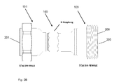
- Fig. 2A . 2 B show the adapter module 100, which implements an N-coupling with a 7/16 DIN connection according to one embodiment.
- the first connection module 101 is accommodated, for example, in a 7/16 DIN connector having an outer terminal 201. Furthermore, a nut 202 is provided at the end to ensure a secure connection to the first connection module 101.
- the first connection module further comprises an N-type connector with a coupling terminal 203, eg output, in which as with respect Fig. 1 described is the ferromagnetic powder 113 may have.
- the second connection module 109 is housed in a 7/16 DIN socket which has an outer terminal 205. Furthermore, a thread 206 is provided at the end to ensure a secure connection to the second connection module 109.
- the second connection module 109 For connection to the first connection module 101, the second connection module 109 comprises a coupling terminal 207, for example an output, which is designed as an N socket.
- the connection modules 101, 109 are screwed together by means of the nut 209.
- the terminals 203 and 207 are brought together, which creates an N-coupling in the presently exemplary case.
- the adapter 100 can be connected to a transmitter and / or receiver or to a signal source.
- Fig. 2B is the adapter off Fig. 2A shown in the connected state, in which the N-coupling is realized.
- the adapter 100 can efficiently realize a passive intermodulation source (PIM source).
- PIM source passive intermodulation source
- the ferromagnetic powder 113 contains, for example, nickel, steel and / or iron.
- the ferromagnetic powder 113 contains, for example, nickel, steel and / or iron.
- the body of the adapter 100 for example, as shown in FIG Fig. 2A and 2 B each having a 7/16 male to N male adapter and a 7/16 female to N female adapter connected to the coupling terminals 203,207 respectively.
- any other N-male and N-female adapters may be used for this because the concept described herein allows for the production of PIM sources of any type of male / female type.
- arrows indicate exemplary locations into which the ferromagnetic powder 113 may be introduced without causing high return loss values.
- the locations where the ferromagnetic powder 113 is to be introduced are cleaned in a dust-free and fat-free manner in the first step.
- the temperature-resistant adhesive is dropped onto the spots.
- Particularly suitable for this purpose are single component reaction adhesives based on cyanoacrylate.
- a previously e.g. empirically or by means of a look-up table certain amount of the ferromagnetic powder 113 introduced to the prepared with the adhesive bodies.
- the N-plug 101 contaminated with the ferromagnetic powder 113 is blown out, for example, with compressed air. At this time, the ferromagnetic powder 113 not fixed by the adhesive is removed from the plug 101, preventing the generation of undesirable effects.
- the N-connector 101 is connected to the N-socket 109 and tightened with a torque of, for example, 5 Nm.
- an optional PIM power meter is used to check which PIM power is generated in the adapter 100. If the PIM power does not match the target value, the N-connector 101 and N-socket 109 connection is opened again to adapt the amount of the ferromagnetic powder 113.
- the PIM power can be varied, for example increased.
- the PIM performance can be reduced. The described procedure is repeated until the desired PIM power is produced by the adapter 100.
- connection of the N-type connector 101 to the N-type socket 109 is optionally sealed by using an anti-reopening adhesive.
Landscapes
- Details Of Connecting Devices For Male And Female Coupling (AREA)
Abstract
Description
- Die vorliegende Erfindung betrifft die passive Intermodulation.
- Passive Intermodulation (PIM) bezeichnet den Vorgang, wenn sich zwei oder mehrere Signale an einer passiven Komponente mit nicht linearen Eigenschaften mischen und dabei zusätzliche unerwünschte Signale entstehen. Die dabei entstehenden Signale werden als passive Intermodulationsprodukte bezeichnet. [1] Ausgehend von zwei Signalen, die sich an einer passiven Komponente mit nicht linearen Eigenschaften mischen, treten folgende Frequenzen auf.

- Dabei sind f 1 und f 2 die Input-Frequenzen und fIntermodulation ist die Frequenz des passiven Intermodulationsprodukts. Die Werte m und n sind Festkommazahlen, also entweder null, positiv oder negativ. Die Summe aus |m| und |n| ergibt den Grad des Intermodulationsprodukts N.

- Die spektrale Breite der entstandenen passiven Intermodulationsprodukte ändert sich annähernd proportional zu den anregenden Signalen. Produkte 3. Ordnung haben die dreifache spektrale Breite wie die Ursprungssignale, Produkte 5.Ordnung haben die fünffache spektrale Breite wie die Ursprungssignale und so weiter.
- Eine Änderung der kombinierten Leistung ΔPi der Eingangssignale steht zur Änderung der Leistung der passiven Intermodulationsprodukte ΔPIM
N der Ordnung N in dem in der folgenden Formel dargestellten Verhältnis, wenn die Leistungen in der logarithmischen Einheit dB verwendet werden:
- Das bedeutet zum Beispiel, dass bei einem Anstieg der kombinierten Leistung der Input-Signale die auf eine passive Komponente mit nicht linearen Eigenschaften einwirken um 1dB, die Leistung eines passiven Intermodulationsprodukts der dritten Ordnung um 3dB ansteigt.
- Die Frequenz der Input-Signale hat dabei keine Auswirkung auf die Leistung der passiven Intermodulationsprodukte.
- Das Problem mit passiver Intermodulation in Mobilfunknetzen ist durch die unterschiedlichen Leistungen im Sende- und Empfangsfrequenzbereich bedingt. Die Empfängerempfindlichkeit der Mobilfunkbasisstationen ist daher recht hoch, um die mit niedriger Leistung ausgesendeter Signale der Endgeräte zu verwerten. Die hohe Empfindlichkeit des für schwache Signale ausgelegten Empfängers macht den für den Empfang vorgesehenen Frequenzbereich in besonderem Maße anfällig für Störungen und Beeinflussungen durch höhere Leistung und Feldstärke, die in diesem Frequenzbereich auftritt. Gleichzeitig wird an den Mobilfunkbasisstationen mit hohen Leistungen gesendet. Die passiven Intermodulationsprodukte, die an passiven Komponenten mit nicht linearen Eigenschaften im Sendebereich der Mobilfunkbasisstationen entstehen, können, bedingt durch die Nachbarschaft der Sende- und Emfpangsfrequenzbereiche, direkt auf den Emfpangsfrequenzbereich der Mobilfunkbasisstationen wirken. Passive Intermodulation ist jedoch kein Mobilfunk spezifisches Problem und kann in allen Funksystemen auftreten.
- Um den Intermodulationspegel passiver HF- und Mikrowellenbauteile feststellen zu können, bedarf es speziell dafür entwickelter Prüfverfahren. Das Prinzip eines PIM-Prüfverfahrens ist beispielsweise in der Norm DIN EN 62037-1 beschrieben. Ein PIM-Meßgerät, welches das in der obigen Norm beschriebene Prinzip eines PIM Prüfverfahren ausführt, umfasst in der Regel einen Sender und einen Empfänger. Das Meßgerät erzeugt zwei definierte Hochleistungssignale, welche sich im Frequenzbereich des zu testenden Prüflings befinden und die im Prüfling entstehenden Intermodulationsprodukte empfangen und auswerten. Zur Erzeugung passiver Intermodulation bedarf es eines zusätzlichen Elementes, das die passive Intermodulation bewirkt und oft als Quelle der Intermodulation bezeichnet wird. Als Quelle der Intermodulation können ferromagnetische Bauelemente eingesetzt werden. Nachteilig an den bekannten Quellen der Intermodulation ist jedoch, dass sie nicht stoßfest und in der Regel nicht temperaturstabil sind.
- Es ist die Aufgabe der vorliegenden Erfindung, ein passives Element zur Erzeugung der passiven Intermodulation anzugeben, das stoßfest und temperaturstabil in einem Stecker-Buchse-System integrierbar ist und dessen Intermodulationsnennwerte in Abhängigkeit von Eingangsleistung und Frequenz möglichst konstant sind.
- Diese Aufgabe wird durch die Merkmale der unabhängigen Ansprüche gelöst. Vorteilhafte Weiterbildungsformen sind Gegenstand der abhängigen Ansprüche, der Beschreibung sowie der beiliegenden Figuren.
- Gemäß einem ersten Aspekt betrifft die Erfindung ein Adaptermodul zum Erzeugen einer passiven Intermodulation, mit einem ersten Verbindungselement mit einem ersten Gehäuse, das eine Gehäusenische begrenzt, in welcher ein erster leitfähiger Kontakt angeordnet ist, einem zweiten Verbindungselement mit einem zweiten leitfähigen Kontakt, wobei das erste Verbindungselement und das zweite Verbindungselement miteinander verbindbar sind, um den ersten leitfähigen Kontakt und den zweiten leitfähigen Kontakt elektrisch zu verbinden, und einem ferromagnetischen Pulver zur Beeinflussung eines magnetischen Feldes für die Intermodulation, wobei das ferromagnetische Pulver in der Gehäusenische stoffschlüssig fixiert ist und den ersten leitfähigen Kontakt zumindest teilweise umgibt und von dem ersten elektrischen Kontakt elektrisch isoliert ist.
- Das Adaptermodul ist vollständig passiv, wobei die Intermodulationsleistung durch das ferromagnetische Pulver beeinflusst wird. Das ferromagnetische Pulver beeinflusst dabei aufgrund dessen ferromagnetischer Eigenschaften beispielsweise das äußere magnetische bzw. elektromagnetische Feld des ersten leitfähigen Kontaktes, wodurch die Leistung der Intermodulationsfrequenzen bzw. -produkte beeinflußt wird.
- Durch die stoffschlüssige Fixierung des ferromagnetischen Pulvers wird sichergestellt, dass nur die für die Intermodulationseigenschaften gewünschte oder benötigte Pulvermenge im Adaptermodul verbleibt. Außerdem wird so sichergestellt, dass das ferromagnetische Pulver an der Stelle im Adaptermodul, beispielsweise auf einer den ersten leitfähigen Kontakt umgehenden Isolationsschicht verbleibt, an welcher das Pulver angebracht wurde. Dadurch werden zudem die Stoßfestigkeit und die Temperaturstabilität erhöht. Durch die Verwendung des ferromagnetischen Pulvers wird zudem die Konstanz der Intermodulationswerte über Eingangsleistung und Frequenz verbessert. Das Adaptermodul kann zudem einen beliebigen Stecker-Buchse-Aufbau aufweisen.
- In einer Ausführungsform ist das ferromagnetische Pulver ein Metallpulver, insbesondere ein Eisenpulver. Metallpulver hat die günstigsten ferromagnetischen Eigenschaften für die Beeinflussung der Intermodulation in dem Adapter.
- In einer Ausführungsform ist das ferromagnetische Pulver mittels einer Klebeschicht, insbesondere einer Cyanacrylat-Klebeschicht, in der Gehäusenische stoffschlüssig befestigt. Dadurch wird vorteilhaft sichergestellt, dass das ferromagnetische Pulver an dem Anbringungsort in der gewünschten Menge verbleibt.
- Die für die jeweilige Intermodulationsleistung günstige Pulvermenge kann beispielsweise empirisch oder durch eine Feldsimulation bestimmt und in einer Datenbank abgelegt werden.
- In einer Ausführungsform ist das ferromagnetische Pulver in der Klebeschicht eingebettet. Dadurch kann die Menge des ferromagnetischen Pulvers für die jeweilige Intermodulationsleistung exakt dosiert werden.
- In einer Ausführungsform weist das ferromagnetische Pulver eine Körnung auf, welche nicht größer als 75 Mikrometer ist. Dadurch kann die Menge des ferromagnetischen Pulvers genauer dosiert werden. Zudem hat eine feinere Körnung günstigere ferromagnetische Eigenschaften für die Beeinflussung des Magnetfeldes für die Intermodulation als eine gröbere Körnung.
- In einer Ausführungsform ist der erste leitfähige Kontakt durch eine Hülse berührungsfrei umgeben, wobei das ferromagnetische Pulver an einer Innenwandung der Hülse, welche dem ersten leitfähigen Kontakt zugewandt ist, stoffschlüssig befestigt ist. Dadurch wird in vorteilhafter Weise erreicht, dass das ferromagnetische Pulver um den ersten leitfähigen Kontakt fixiert angeordnet werden kann, ohne den ersten leitfähigen Kontakt zu berühren. Die Hülse ist beispielsweise aus einem dielektrischen Kunststoff geformt.
- In einer Ausführungsform ist der erste leitfähige Kontakt zumindest teilweise durch eine Isolationsschicht ummantelt, wobei das ferromagnetische Pulver auf der Isolationsschicht angeordnet oder in der Isolationsschicht oder eingebettet ist. Dadurch wird in vorteilhafter Weise erreicht, dass das ferromagnetische Pulver um den ersten leitfähigen Kontakt fixiert angeordnet werden kann, ohne den ersten leitfähigen Kontakt zu berühren.
- In einer Ausführungsform ist der erste leitfähige Kontakt ein zylinderförmiger Stift oder eine hülsenförmige Buchse. Das Adaptermodul kann daher als ein Stecker ausgebildet sein, welcher eingangs- bzw. ausgangsseitig bzw.an seinen Enden mit beliebigen Anschlüssen versehen werden kann.
- In einer Ausführungsform weist das ferromagnetische Pulver ein vorbestimmtes Gewicht auf, das einer vorbestimmten Intermodulationsleistung zugeordnet ist.
- In einer Ausführungsform weist das zweite Verbindungselement eine Gehäusenische auf, in welcher ein weiteres ferromagnetisches Pulver stoffschlüssig, insbesondere mittels einer Klebeschicht, verbunden ist und den zweiten leitfähigen Kontakt zumindest teilweise umgibt, wobei das ferromagnetische Pulver von dem zweiten leitfähigen Kontakt zumindest teilweise isoliert ist. Das weitere ferromagnetische Pulver kann in derselben Weise um den zweiten leitfähigen Kontakt wie das ferromagnetische Pulver angeordnet sein.
- In einer Ausführungsform ist der zweite leitfähige Kontakt eine Buchse, in welche der erste leitfähige Kontakt einführbar ist. In diesem Falle kann ferromagnetisches Pulver nur um den Stecker herum oder um den Stecker und um die Buchse herum angeordnet werden. Auf diese Weise können die Pulvermenge sowie die Pulververteilung in Längsrichtung variiert werden.
- In einer Ausführungsform ist der zweite leitfähige Kontakt durch eine Isolationshülse umgeben, wobei das weitere ferromagnetische Pulver auf einer dem zweiten leitfähigen Kontakt abgewandten Oberfläche der Isolationshülse angeordnet oder in der Isolationshülse eingebettet ist. Dadurch kann das ferromagnetische Pulver um den zweiten leitfähigen Kontakt herum in elektrisch isolierter Weise angeordnet werden.
- In einer Ausführungsform ist das zweite Gehäuse mit dem ersten Gehäuse mittels einer Schraubverbindung oder mittels einer Steckverbindung verbindbar oder verbunden. Die beiden Gehäuse können durch unterschiedliche Anschlussformen realisiert werden, über welche der Adapter beispielsweise an einen Signalgenerator angeschlossen werden kann.
- In einer Ausführungsform weist das erste Verbindungselement einen N-Stecker auf, wobei das zweite Verbindungselement eine N-Buchse Buchse, und wobei der N-Stecker in die N-Buchse einführbar ist. N-Stecker und N-Buchsen werden als Anschlussterminals oft für Hochfrequenzsignale verwendet, daher ist die Ausgestaltung des Adapters in einer Standardanschlussform besonders vorteilhaft.
- In einer Ausführungsform das erste Verbindungselement einen elektrischen Anschluss, insbesondere einen 7/16 DIN Anschluss, zur elektrischen Kontaktierung des N-Steckers aufweist, und wobei das zweite Verbindungselement einen elektrischen Anschluss, insbesondere einen 7/16 DIN Anschluss, zur elektrischen Kontaktierung der N-Buchse aufweist.
- Gemäß einem zweiten Aspekt betrifft die Erfindung ein Verfahren zum Herstellen eines Adaptermoduls zum Erzeugen einer passiven Intermodulation, mit: Bereitstellen eines ersten Verbindungselementes mit einem ersten Gehäuse, das eine Gehäusenische begrenzt, in welcher ein erster leitfähiger Kontakt angeordnet ist; Bereitstellen eines zweiten Verbindungselementes mit einem zweiten leitfähigen Kontakt, wobei das erste Verbindungselement und das zweite Verbindungselement miteinander verbindbar sind, um den ersten leitfähigen Kontakt und den zweiten leitfähigen Kontakt elektrisch zu verbinden; und stoffschlüssigem Fixieren eines ferromagnetischen Pulvers in der Gehäusenische zur Beeinflussung eines magnetischen Feldes für die Intermodulation, wobei das ferromagnetische Pulver den ersten leitfähigen Kontakt zumindest teilweise umgibt und von dem ersten elektrischen Kontakt elektrisch isoliert ist. Weitere Herstellungsschritte ergeben sich unmittelbar aus den Merkmalen des Adapters gemäß dem ersten Aspekt.
- In einer Ausführungsform umfasst das Verfahren das Bereitstellen einer Gewichtsmenge des ferromagnetischen Pulvers, welche einer vorbestimmten Intermodulationsleistung zugeordnet ist. Die Zuordnung der Gewichtsmenge zu einer Intermodulationsleistung kann beispielsweise empirisch festgelegt und in einer Datenbank bzw. Look-up-Tabelle abgelegt sein.
- Durch das Adaptermodul können temperaturstabile und konstante PIM Quellen hergestellt werden, welche eine beliebige PIM-Leistung (+-1dB) in Abhängigkeit von Eingangsleistung und Frequenz produzieren können, ohne dabei gleichzeitig auffällige Return Loss Werte als Nebenprodukt entstehen zu lassen. Diese PIM Quellen können aus einer 7/16 Stecker - 7/16 Buchse Kombination erstellt werden, wobei auch andere Stecker-Buchse Typen möglich sind, und lassen sich somit in bereits existierende und geplante Funknetzwerke, beispielsweise zu Testzwecken einbringen. Die PIM-Quellen lassen sich aus günstigen Grundkomponenten schnell mit jeder beliebigen PIM-Leistung (+-1dB) herstellen.
- Weitere Ausführungsformen der Erfindung werden Bezug nehmend auf die beiliegenden Zeichnungen erläutert. Es zeigen:
- Fig. 1
- ein Adaptermodul gemäß einer Ausführungsform; und
- Fig. 2A, 2B
- das Adaptermodul gemäß einer Ausführungsform.
- In
Fig. 1 sind Verbindungselemente 101, 109 eines Adaptermoduls 100 zum Erzeugen einer passiven Intermodulation dargestellt. - Das Adaptermodul 100 umfasst das erste Verbindungselement 101 mit einem ersten Gehäuse 103, das eine Gehäusenische 105 begrenzt, in welcher ein erster leitfähiger Kontakt 107 angeordnet ist.
- Das erste Verbindungselement 101 des Adaptermoduls 100 umfasst ferner ein zweites Verbindungselement 109 mit einem zweiten leitfähigen Kontakt 111, wobei das erste Verbindungselement 103 und das zweite Verbindungselement 109 miteinander verbindbar, beispielsweise ineinander steckbar sind, um den ersten leitfähigen Kontakt 107 und den zweiten leitfähigen Kontakt 111 elektrisch zu verbinden.
- Das erste Verbindungselement 101 des Adaptermoduls 100 umfasst ferner ein ferromagnetisches Pulver 113 zur Beeinflussung eines magnetischen Feldes für die Intermodulation, das wobei das an zumindest einer der durch die Pfeile angezeigten Stelle in der Gehäusenische 105 stoffschlüssig fixiert ist und den ersten leitfähigen Kontakt 107 zumindest teilweise umgibt und von dem ersten elektrischen Kontakt 107 elektrisch isoliert ist. Das ferromagnetische Pulver 113 wird in die durch die gestrichelten Pfeile 114 angedeutete Richtung in die Gehäusenische 105 eingebracht, beispielsweise vermengt mit einem Klebestoff für die stoffschlüssige Verbindung.
- Der erste leitfähige Kontakt 107 kann zumindest abschnittsweise durch eine Isolationsschicht 115 elektrisch isoliert sein. Wie es in
Fig. 1 dargestellt ist, kann das Ferromagnetische Pulver 113 mit der Isolationsschicht 115 stoffschlüssig verbunden sein. - Der erste leitfähige Kontakt 107 kann als ein zylinderförmiger Stift gebildet sein.
- In der Gehäusenische 105 kann ferner eine Hülse 117, beispielsweise eine Isolierhülse, angeordnet sein, welche der ersten leitfähigen Kontakt 107, insbesondere berührungsfrei, umgibt. Die Hülse 117 ist endseitig mit dem Gehäuse 103 verbunden.
- Die Verbindungselemente 101, 109 können miteinander verschraubt werden. Hierzu sind Gewinde 119, 121 vorgesehen.
- Das Adaptermodul 100 umfasst ferner das zweite Verbindungselement 109, das eine Gehäusenische 123 aufweist, in welcher ein weiteres ferromagnetisches Pulver stoffschlüssig, insbesondere mittels einer Klebeschicht, in Analogie zum ferromagnetischen Pulver 113 fixiert sein kann, welches den zweiten leitfähigen Kontakt 111 zumindest teilweise umgibt und von dem zweiten leitfähigen Kontakt 111 zumindest teilweise isoliert ist.
- Die Gehäusenische 123 kann jedoch frei vom ferromagnetischen Pulver sein.
- Die Gehäusenische 123 ist in einem Gehäuse 124 gebildet.
- In der Gehäusenische 123 ist der zweite leitfähige Kontakt 111 angeordnet, welcher eine Buchse sein kann, in welche der erste leitfähige Kontakt 107 einführbar ist.
- Der zweite leitfähige Kontakt kann zumindest abschnittsweise durch eine Isolationsschicht 125 umgeben sein. Auf der Isolationsschicht 125 kann gemäß einer Ausführungsform das weitere ferromagnetische Pulver stoffschlüssig befestigt sein.
- Der zweite leitfähige Kontakt 111 kann ferner durch eine Isolationshülse 127 umgeben sein, wobei das weitere ferromagnetische Pulver auf einer dem zweiten leitfähigen Kontakt abgewandten Oberfläche der Isolationshülse 127 angeordnet oder in der Isolationshülse eingebettet sein kann.
- Das Adaptermodul 100 kann beidseitig elektrisch kontaktiert werden, was in
Fig. 1 nicht dargestellt ist. -
Fig. 2A ,2B zeigen das Adaptermodul 100, das gemäß einer Ausführungsform eine N-Kopplung mit einem 7 / 16 DIN-Anschluß realisiert. - Das erste Verbindungsmodul 101 ist beispielsweise in einem 7 / 16 DIN-Stecker untergebracht, welcher einen äußeren Anschluß 201 aufweist. Endseitig ist ferner eine Mutter 202 vorgesehen, um eine sichere Anbindung an das erste Verbindungsmodul 101 zu gewährleisten. Das erste Verbindungsmodul umfasst ferner einen N-Stecker mit einem Kupplungsterminal 203, z.B. Ausgang, in welchem wie bezüglich
Fig. 1 beschrieben ist das ferromagnetische Pulver 113 aufweisen kann. - Das zweite Verbindungsmodul 109 ist in einer 7 / 16 DIN-Buchse untergebracht, welche einen äußeren Anschluß 205 aufweist. Endseitig ist ferner ein Gewinde 206 vorgesehen, um eine sichere Anbindung an das zweite Verbindungsmodul 109 zu gewährleisten. Zur Verbindung mit der ersten Verbindungsmodul 101 umfasst das zweite Verbindungsmodul 109 eine Kupplungsterminal 207, beispielswiese Ausgang, welcher als eine N-Buchse ausgeführt ist. Die Verbindungsmodule 101, 109 werden miteinander mittels der Mutter 209 verschraubt.
- Die Terminals 203 und 207 werden zusammengeführt, wodurch in vorliegend beispielhaften Fall eine N-Kupplung entsteht.
- Über die Anschlüsse 201 und 205 kann der Adapter 100 an einen Sender- und/oder Empfänger bzw. an eine Signalquelle angeschlossen werden.
- In
Fig. 2B ist der Adapter ausFig. 2A im verbundenen Zustand dargestellt, in welchem die N-Kupplung realisiert ist. - Mit dem Adapter 100 kann effizient eine passive Intermodulationsquelle (PIM-Quelle) realisiert werde.
- Zum Produzieren der PIM-Leistung in dem Adapter 100 werden physikalische Phänomene, welche durch Ferromagnetika entstehen, genutzt. Hierbei wird das ferromagnetische Pulver 113 eingesetzt, das beispielsweise Nickel, Stahl und/oder Eisen enthält. Dadurch können gezielt nichtlineare Hysterese-Effekte und nichtlineare Strom-Spannungsverhältnisse ausgelöst werden. Dies hat die Ursache in der nicht linearen Beziehung zwischen dem magnetischen Feld (H) und der magnetischen Flussdichte (B) aufgrund der Abhängigkeit der magnetischen Permeabilität mit dem angelegten magnetischen Feld.
- Als Körper des Adapters 100 dienen beispielsweise, wie es in
Fig. 2A und2B dargestellt ist, jeweils ein 7/16 Stecker auf N-Stecker Adapter und ein 7/16 Buchse auf N-Buchse Adapter, welche an den Kupplungsterminalen 203, 207 verbunden werden. - Es kann hierzu jedoch auch andere beliebige Adapter auf N-Stecker und N-Buchse verwendet werden, weil das hierin beschriebene Konzept das Herstellen von PIM-Quellen mit beliebigen Stecker-Buchse-Typen ermöglicht.
- Zum Erzeugen der nichtlinearen Hysterese-Effekte und der nichtlinearer Strom-Spannungsverhältnisse wird vor dem Verbinden der N-Ausgänge 203, 207 das ferromagnetische Pulver 113, beispielsweise Eisenpulver, beispielsweise mit der Körnung <=75µm in den N-Stecker 101 eingebracht und mit einem temperaturbeständigen Klebstoff fixiert.
- Die Menge des eingebrachten ferromagnetischen Pulvers 113 und die Stelle an der das ferromagnetischen Pulvers 113 im N-Stecker 101 fixiert wird, beeinflussen die PIM-Leistung, welche im Folgenden entsteht.
- In
Fig. 1 sind mit den Pfeilen beispielhafte Stellen markiert, in die das ferromagnetische Pulver 113 eingebracht werden kann, ohne dass hohe Return-Loss Werte ausgelöst werden. - Im Folgenden wird die Prozedur zum Herstellen des Adapters 100 schrittweise beschrieben.
- Die Stellen an denen das das ferromagnetische Pulver 113 eingebracht werden soll, werden im ersten Schritt staubfrei und fettfrei gereinigt. Im zweiten Schritt wird der temperaturbeständige Klebstoff auf die Stellen geträufelt. Besonders geeignet sind hierfür Einzelkomponenten-Reaktionsklebstoffe auf Basis von Cyanacrylat.
- Im dritten Schritt wird eine vorher, z.B. empirisch oder anhand einer Look-up-Tabelle bestimmte Menge des ferromagnetischen Pulvers 113 auf die mit dem Klebstoff präparierten Stellen eingebracht.
- Im vierten Schritt wird der mit dem das ferromagnetischen Pulver 113 kontaminierte N-Stecker 101 beispielswiese mit Druckluft ausgeblasen. Dabei wird das nicht durch den Klebstoff fixierte das ferromagnetische Pulver 113 aus dem Stecker 101 entfernt, was das Entstehen von nicht erwünschten Effekte verhindert.
- Im fünften Schritt wird der N-Stecker 101 mit der N-Buchse 109 verbunden und mit einem Drehmoment von beispielsweise 5 Nm angezogen.
- Im sechsten Schritt wird optional mit einem PIM-Leistungsmesser überprüft, welche PIM-Leistung in dem Adapter 100 entsteht. Entspricht die PIM-Leistung nicht dem angestrebten Wert, so wird die Verbindung aus N-Stecker 101 und N-Buchse 109 erneut geöffnet, um die Menge des ferromagnetischen Pulvers 113 zu adaptieren.
- Durch Einbringen weiteren das ferromagnetischen Pulvern 113 oder durch Umverteilen des eingebrachten das ferromagnetischen Pulvers 113 im N-Stecker 101 und/oder in der N-Buchse 109 kann die PIM-Leistung variiert, beispielsweise erhöht werden.
- Durch Entfernen von bereits eingebrachtem das ferromagnetischen Pulver 113 oder dem Umverteilen des eingebrachten das ferromagnetischen Pulvers 113 im N-Stecker 101 und/oder in der N-Buchse 109, kann die PIM-Leistung reduziert werden. Die beschriebene Prozedur wird solange wiederholt, bis die angestrebte PIM-Leistung von dem Adapter 100 produziert wird.
- Im folgenden siebten Arbeitsschritt wird die Verbindung des N-Steckers 101 mit der N-Buchse 109 durch das Verwenden eines Klebstoffs gegen Wiederöffnen optional versiegelt.
- So können zur Herstellung einer Intermodulationsleistung von -80dBm etwa 2g Eisenpulver mit der Körnung <=75µm an die in
Fig. 1 mit Pfeilen markierten Stellen eingebracht werden.
Claims (14)
- Adaptermodul (100) zum Erzeugen einer passiven Intermodulation, mit:einem ersten Verbindungselement (101) mit einem ersten Gehäuse (103), das eine Gehäusenische (105) begrenzt, in welcher ein erster leitfähiger Kontakt (107) angeordnet ist;einem zweiten Verbindungselement (109) mit einem zweiten leitfähigen Kontakt (111), wobei das erste Verbindungselement (101) und das zweite Verbindungselement (109) miteinander verbindbar sind, um den ersten leitfähigen Kontakt (107) und den zweiten leitfähigen Kontakt (111) elektrisch zu verbinden; undeinem ferromagnetischen Pulver (113) zur Beeinflussung eines magnetischen Feldes für die Intermodulation, wobei das ferromagnetische Pulver (113) in der Gehäusenische (105) stoffschlüssig fixiert ist und den ersten leitfähigen Kontakt (107) zumindest teilweise umgibt und von dem ersten elektrischen Kontakt (107) elektrisch isoliert ist.
- Adaptermodul (100) nach Anspruch 1, wobei das ferromagnetische Pulver (113) ein Metallpulver, insbesondere ein Eisenpulver, ist.
- Adaptermodul (100) nach einem der vorstehenden Ansprüche, wobei das ferromagnetische Pulver (113) mittels einer Klebeschicht, insbesondere einer Cyanacrylat-Klebeschicht, in der Gehäusenische (105) stoffschlüssig befestigt ist.
- Adaptermodul (100) nach Anspruch 3, wobei das ferromagnetische Pulver (113) in der Klebeschicht eingebettet ist.
- Adaptermodul (100) nach einem der vorstehenden Ansprüche, wobei das ferromagnetische Pulver (113) eine Körnung aufweist, welche nicht größer als 75 Mikrometer ist.
- Adaptermodul (100) nach einem der vorstehenden Ansprüche, wobei der erste leitfähige Kontakt (107) durch eine Hülse (117) berührungsfrei umgeben ist, wobei das ferromagnetische Pulver (117) an einer Innenwandung der Hülse (117), welche dem ersten leitfähigen Kontakt (107) zugewandt ist, stoffschlüssig befestigt ist.
- Adaptermodul (100) nach einem der vorstehenden Ansprüche, wobei der erste leitfähige Kontakt (107) zumindest teilweise durch eine Isolationsschicht (115) ummantelt ist, und wobei das ferromagnetische Pulver (113) auf der Isolationsschicht (115) oder in der Isolationsschicht (115) angeordnet ist.
- Adaptermodul (100) nach einem der vorstehenden Ansprüche, wobei der erste leitfähige Kontakt (107) ein zylinderförmiger Stift oder eine hülsenförmige Buchse ist.
- Adaptermodul (100) nach einem der vorstehenden Ansprüche, wobei das ferromagnetische Pulver (113) ein vorbestimmtes Gewicht aufweist, das einer vorbestimmten Intermodulationsleistung zugeordnet ist.
- Adaptermodul (100) nach einem der vorstehenden Ansprüche, wobei das zweite Verbindungselement (109) eine Gehäusenische (123) aufweist, in welcher ein weiteres ferromagnetisches Pulver stoffschlüssig, insbesondere mittels einer Klebeschicht, verbunden ist, den zweiten leitfähigen Kontakt (111) zumindest teilweise umgibt und von dem zweiten leitfähigen Kontakt (111) zumindest teilweise isoliert ist.
- Adaptermodul nach Anspruch 10, wobei der zweite leitfähige Kontakt (111) durch eine Isolationshülse (127) umgeben ist, wobei das weitere ferromagnetische Pulver auf einer dem zweiten leitfähigen Kontakt (111) abgewandten Oberfläche der Isolationshülse (127) angeordnet oder in der Isolationshülse (127) eingebettet ist.
- Adaptermodul nach einem der vorstehenden Ansprüche, wobei das erste Verbindungselement (101) einen elektrischen Anschluss, insbesondere einen 7/16 DIN Anschluss zur elektrischen Kontaktierung des Adaptermoduls (100) aufweist, und wobei das zweite Verbindungselement (109) einen elektrischen Anschluss, insbesondere einen 7/16 DIN Anschluss, zur elektrischen Kontaktierung des Adaptermoduls (100) aufweist.
- Verfahren zum Herstellen eines Adaptermoduls zum Erzeugen einer passiven Intermodulation, mit:Bereitstellen eines ersten Verbindungselementes (101) mit einem ersten Gehäuse (103), das eine Gehäusenische (105) begrenzt, in welcher ein erster leitfähiger Kontakt (107) angeordnet ist;Bereitstellen eines zweiten Verbindungselementes (109) mit einem zweiten leitfähigen Kontakt (111), wobei das erste Verbindungselement (101) und das zweite Verbindungselement (103) miteinander verbindbar sind, um den ersten leitfähigen Kontakt (107) und den zweiten leitfähigen Kontakt (111) elektrisch zu verbinden; undstoffschlüssigem Fixieren eines ferromagnetischen Pulvers (113) in der Gehäusenische (105) zur Beeinflussung eines magnetischen Feldes für die Intermodulation, wobei das ferromagnetische Pulver (113) den ersten leitfähigen Kontakt (107) zumindest teilweise umgibt und von dem ersten elektrischen Kontakt (107) elektrisch isoliert ist.
- Verfahren nach Anspruch 13, mit:Bereitstellen einer Gewichtsmenge des ferromagnetischen Pulvers (113), welche einer vorbestimmten Intermodulationsleistung zugeordnet ist.
Priority Applications (1)
| Application Number | Priority Date | Filing Date | Title |
|---|---|---|---|
| EP16171081.9A EP3249760B1 (de) | 2016-05-24 | 2016-05-24 | Adaptermodul zum erzeugen einer passiven intermodulation |
Applications Claiming Priority (1)
| Application Number | Priority Date | Filing Date | Title |
|---|---|---|---|
| EP16171081.9A EP3249760B1 (de) | 2016-05-24 | 2016-05-24 | Adaptermodul zum erzeugen einer passiven intermodulation |
Publications (2)
| Publication Number | Publication Date |
|---|---|
| EP3249760A1 true EP3249760A1 (de) | 2017-11-29 |
| EP3249760B1 EP3249760B1 (de) | 2018-05-23 |
Family
ID=56098014
Family Applications (1)
| Application Number | Title | Priority Date | Filing Date |
|---|---|---|---|
| EP16171081.9A Active EP3249760B1 (de) | 2016-05-24 | 2016-05-24 | Adaptermodul zum erzeugen einer passiven intermodulation |
Country Status (1)
| Country | Link |
|---|---|
| EP (1) | EP3249760B1 (de) |
Citations (1)
| Publication number | Priority date | Publication date | Assignee | Title |
|---|---|---|---|---|
| US20140266496A1 (en) * | 2013-03-13 | 2014-09-18 | International Business Machines Corporation | Microwave connector with filtering properties |
-
2016
- 2016-05-24 EP EP16171081.9A patent/EP3249760B1/de active Active
Patent Citations (1)
| Publication number | Priority date | Publication date | Assignee | Title |
|---|---|---|---|---|
| US20140266496A1 (en) * | 2013-03-13 | 2014-09-18 | International Business Machines Corporation | Microwave connector with filtering properties |
Also Published As
| Publication number | Publication date |
|---|---|
| EP3249760B1 (de) | 2018-05-23 |
Similar Documents
| Publication | Publication Date | Title |
|---|---|---|
| DE69820101T2 (de) | Überspannungsunterdrückungsvorrichtung | |
| DE69403466T2 (de) | Vorrichtung zur messung von elektrischem strom mit einem auf magnetfluss ansprechenden wandler, insbesondere für die verwendung bei elektrisch betriebenen fahrzeugen | |
| WO2014006150A1 (de) | Hohlleitereinkopplung, hochfrequenzmodul, füllstandradar und verwendung | |
| DE102009028362A1 (de) | Strahllagemonitor für Elektronen-Linearbeschleuniger | |
| DE102015105657A1 (de) | Verbinder für dielektrische Wellenleiter | |
| EP3433897A1 (de) | Deckel für ein gehäuse, batteriesensor und verfahren zum herstellen eines batteriesensors | |
| WO2007039269A1 (de) | Koaxialverbinder | |
| DE112013004185B4 (de) | Richtkoppler | |
| DE102018104264A1 (de) | Verfahren zur herstellung von mindestens einem hochfrequenz-kontaktelement oder einer hochfrequenz-kontaktelement-anordnung sowie zugehörige vorrichtung | |
| DE102004045707A1 (de) | Antenne | |
| DE102012211738B4 (de) | Breitbandrichtkoppler | |
| EP3249760B1 (de) | Adaptermodul zum erzeugen einer passiven intermodulation | |
| EP2489095A1 (de) | Antennenkoppler | |
| EP0810445A1 (de) | Verfahren zur Bestimmung der Schirmwirkung einer abgeschirmten Verkabelungsstrecke | |
| DE102007043887A1 (de) | Steckverbinder mit integrierter Platine | |
| DE102007008575B4 (de) | Antennenvorrichtung mit ionenimplantierter Resonanzstruktur | |
| DE3833696C2 (de) | Signalverarbeitungsvorrichtung und Verfahren zum Ausdehnen des flachen Frequenzgangs einer Komponente | |
| DE69216743T2 (de) | Einrichtung für in situ Ultrahochfrequenztests mit grosser Bandbreite | |
| DE202008017972U1 (de) | Koppler mit elektronisch variierbarem Abschluss | |
| EP3699558A1 (de) | Radarsenderanordnung mit integrierter antenne | |
| DE102005005751B4 (de) | Testvorrichtung mit reflexionsarmer Signalverteilung | |
| DE102021214990A1 (de) | Steckverbindung und Verfahren zum Prüfen einer Steckverbindung | |
| WO2016102172A1 (de) | Hochfrequenz-prüfstift | |
| DE102009023374A1 (de) | Antennenvorrichtung | |
| DE102023204268A1 (de) | Vorrichtung zur Anregung eines spin-basierten Quantensystems |
Legal Events
| Date | Code | Title | Description |
|---|---|---|---|
| PUAI | Public reference made under article 153(3) epc to a published international application that has entered the european phase |
Free format text: ORIGINAL CODE: 0009012 |
|
| STAA | Information on the status of an ep patent application or granted ep patent |
Free format text: STATUS: REQUEST FOR EXAMINATION WAS MADE |
|
| 17P | Request for examination filed |
Effective date: 20170420 |
|
| AK | Designated contracting states |
Kind code of ref document: A1 Designated state(s): AL AT BE BG CH CY CZ DE DK EE ES FI FR GB GR HR HU IE IS IT LI LT LU LV MC MK MT NL NO PL PT RO RS SE SI SK SM TR |
|
| AX | Request for extension of the european patent |
Extension state: BA ME |
|
| GRAP | Despatch of communication of intention to grant a patent |
Free format text: ORIGINAL CODE: EPIDOSNIGR1 |
|
| STAA | Information on the status of an ep patent application or granted ep patent |
Free format text: STATUS: GRANT OF PATENT IS INTENDED |
|
| INTG | Intention to grant announced |
Effective date: 20180102 |
|
| GRAS | Grant fee paid |
Free format text: ORIGINAL CODE: EPIDOSNIGR3 |
|
| GRAA | (expected) grant |
Free format text: ORIGINAL CODE: 0009210 |
|
| STAA | Information on the status of an ep patent application or granted ep patent |
Free format text: STATUS: THE PATENT HAS BEEN GRANTED |
|
| AK | Designated contracting states |
Kind code of ref document: B1 Designated state(s): AL AT BE BG CH CY CZ DE DK EE ES FI FR GB GR HR HU IE IS IT LI LT LU LV MC MK MT NL NO PL PT RO RS SE SI SK SM TR |
|
| REG | Reference to a national code |
Ref country code: GB Ref legal event code: FG4D Free format text: NOT ENGLISH |
|
| REG | Reference to a national code |
Ref country code: CH Ref legal event code: EP |
|
| REG | Reference to a national code |
Ref country code: IE Ref legal event code: FG4D Free format text: LANGUAGE OF EP DOCUMENT: GERMAN |
|
| REG | Reference to a national code |
Ref country code: DE Ref legal event code: R096 Ref document number: 502016001087 Country of ref document: DE |
|
| REG | Reference to a national code |
Ref country code: AT Ref legal event code: REF Ref document number: 1002268 Country of ref document: AT Kind code of ref document: T Effective date: 20180615 |
|
| REG | Reference to a national code |
Ref country code: FR Ref legal event code: PLFP Year of fee payment: 3 |
|
| REG | Reference to a national code |
Ref country code: NL Ref legal event code: MP Effective date: 20180523 |
|
| REG | Reference to a national code |
Ref country code: LT Ref legal event code: MG4D |
|
| PG25 | Lapsed in a contracting state [announced via postgrant information from national office to epo] |
Ref country code: BG Free format text: LAPSE BECAUSE OF FAILURE TO SUBMIT A TRANSLATION OF THE DESCRIPTION OR TO PAY THE FEE WITHIN THE PRESCRIBED TIME-LIMIT Effective date: 20180823 Ref country code: FI Free format text: LAPSE BECAUSE OF FAILURE TO SUBMIT A TRANSLATION OF THE DESCRIPTION OR TO PAY THE FEE WITHIN THE PRESCRIBED TIME-LIMIT Effective date: 20180523 Ref country code: SE Free format text: LAPSE BECAUSE OF FAILURE TO SUBMIT A TRANSLATION OF THE DESCRIPTION OR TO PAY THE FEE WITHIN THE PRESCRIBED TIME-LIMIT Effective date: 20180523 Ref country code: ES Free format text: LAPSE BECAUSE OF FAILURE TO SUBMIT A TRANSLATION OF THE DESCRIPTION OR TO PAY THE FEE WITHIN THE PRESCRIBED TIME-LIMIT Effective date: 20180523 Ref country code: LT Free format text: LAPSE BECAUSE OF FAILURE TO SUBMIT A TRANSLATION OF THE DESCRIPTION OR TO PAY THE FEE WITHIN THE PRESCRIBED TIME-LIMIT Effective date: 20180523 Ref country code: NO Free format text: LAPSE BECAUSE OF FAILURE TO SUBMIT A TRANSLATION OF THE DESCRIPTION OR TO PAY THE FEE WITHIN THE PRESCRIBED TIME-LIMIT Effective date: 20180823 |
|
| PG25 | Lapsed in a contracting state [announced via postgrant information from national office to epo] |
Ref country code: RS Free format text: LAPSE BECAUSE OF FAILURE TO SUBMIT A TRANSLATION OF THE DESCRIPTION OR TO PAY THE FEE WITHIN THE PRESCRIBED TIME-LIMIT Effective date: 20180523 Ref country code: HR Free format text: LAPSE BECAUSE OF FAILURE TO SUBMIT A TRANSLATION OF THE DESCRIPTION OR TO PAY THE FEE WITHIN THE PRESCRIBED TIME-LIMIT Effective date: 20180523 Ref country code: NL Free format text: LAPSE BECAUSE OF FAILURE TO SUBMIT A TRANSLATION OF THE DESCRIPTION OR TO PAY THE FEE WITHIN THE PRESCRIBED TIME-LIMIT Effective date: 20180523 Ref country code: GR Free format text: LAPSE BECAUSE OF FAILURE TO SUBMIT A TRANSLATION OF THE DESCRIPTION OR TO PAY THE FEE WITHIN THE PRESCRIBED TIME-LIMIT Effective date: 20180824 Ref country code: LV Free format text: LAPSE BECAUSE OF FAILURE TO SUBMIT A TRANSLATION OF THE DESCRIPTION OR TO PAY THE FEE WITHIN THE PRESCRIBED TIME-LIMIT Effective date: 20180523 |
|
| REG | Reference to a national code |
Ref country code: BE Ref legal event code: MM Effective date: 20180531 |
|
| PG25 | Lapsed in a contracting state [announced via postgrant information from national office to epo] |
Ref country code: EE Free format text: LAPSE BECAUSE OF FAILURE TO SUBMIT A TRANSLATION OF THE DESCRIPTION OR TO PAY THE FEE WITHIN THE PRESCRIBED TIME-LIMIT Effective date: 20180523 Ref country code: SK Free format text: LAPSE BECAUSE OF FAILURE TO SUBMIT A TRANSLATION OF THE DESCRIPTION OR TO PAY THE FEE WITHIN THE PRESCRIBED TIME-LIMIT Effective date: 20180523 Ref country code: RO Free format text: LAPSE BECAUSE OF FAILURE TO SUBMIT A TRANSLATION OF THE DESCRIPTION OR TO PAY THE FEE WITHIN THE PRESCRIBED TIME-LIMIT Effective date: 20180523 Ref country code: CZ Free format text: LAPSE BECAUSE OF FAILURE TO SUBMIT A TRANSLATION OF THE DESCRIPTION OR TO PAY THE FEE WITHIN THE PRESCRIBED TIME-LIMIT Effective date: 20180523 Ref country code: PL Free format text: LAPSE BECAUSE OF FAILURE TO SUBMIT A TRANSLATION OF THE DESCRIPTION OR TO PAY THE FEE WITHIN THE PRESCRIBED TIME-LIMIT Effective date: 20180523 Ref country code: DK Free format text: LAPSE BECAUSE OF FAILURE TO SUBMIT A TRANSLATION OF THE DESCRIPTION OR TO PAY THE FEE WITHIN THE PRESCRIBED TIME-LIMIT Effective date: 20180523 |
|
| REG | Reference to a national code |
Ref country code: IE Ref legal event code: MM4A |
|
| REG | Reference to a national code |
Ref country code: DE Ref legal event code: R097 Ref document number: 502016001087 Country of ref document: DE |
|
| PG25 | Lapsed in a contracting state [announced via postgrant information from national office to epo] |
Ref country code: SM Free format text: LAPSE BECAUSE OF FAILURE TO SUBMIT A TRANSLATION OF THE DESCRIPTION OR TO PAY THE FEE WITHIN THE PRESCRIBED TIME-LIMIT Effective date: 20180523 Ref country code: IT Free format text: LAPSE BECAUSE OF FAILURE TO SUBMIT A TRANSLATION OF THE DESCRIPTION OR TO PAY THE FEE WITHIN THE PRESCRIBED TIME-LIMIT Effective date: 20180523 |
|
| PG25 | Lapsed in a contracting state [announced via postgrant information from national office to epo] |
Ref country code: LU Free format text: LAPSE BECAUSE OF NON-PAYMENT OF DUE FEES Effective date: 20180524 Ref country code: MC Free format text: LAPSE BECAUSE OF FAILURE TO SUBMIT A TRANSLATION OF THE DESCRIPTION OR TO PAY THE FEE WITHIN THE PRESCRIBED TIME-LIMIT Effective date: 20180523 |
|
| PLBE | No opposition filed within time limit |
Free format text: ORIGINAL CODE: 0009261 |
|
| STAA | Information on the status of an ep patent application or granted ep patent |
Free format text: STATUS: NO OPPOSITION FILED WITHIN TIME LIMIT |
|
| PG25 | Lapsed in a contracting state [announced via postgrant information from national office to epo] |
Ref country code: IE Free format text: LAPSE BECAUSE OF NON-PAYMENT OF DUE FEES Effective date: 20180524 |
|
| 26N | No opposition filed |
Effective date: 20190226 |
|
| PG25 | Lapsed in a contracting state [announced via postgrant information from national office to epo] |
Ref country code: BE Free format text: LAPSE BECAUSE OF NON-PAYMENT OF DUE FEES Effective date: 20180531 |
|
| REG | Reference to a national code |
Ref country code: DE Ref legal event code: R082 Ref document number: 502016001087 Country of ref document: DE |
|
| PG25 | Lapsed in a contracting state [announced via postgrant information from national office to epo] |
Ref country code: AL Free format text: LAPSE BECAUSE OF FAILURE TO SUBMIT A TRANSLATION OF THE DESCRIPTION OR TO PAY THE FEE WITHIN THE PRESCRIBED TIME-LIMIT Effective date: 20180523 |
|
| REG | Reference to a national code |
Ref country code: CH Ref legal event code: PL |
|
| PG25 | Lapsed in a contracting state [announced via postgrant information from national office to epo] |
Ref country code: CH Free format text: LAPSE BECAUSE OF NON-PAYMENT OF DUE FEES Effective date: 20190531 Ref country code: MT Free format text: LAPSE BECAUSE OF FAILURE TO SUBMIT A TRANSLATION OF THE DESCRIPTION OR TO PAY THE FEE WITHIN THE PRESCRIBED TIME-LIMIT Effective date: 20180523 Ref country code: LI Free format text: LAPSE BECAUSE OF NON-PAYMENT OF DUE FEES Effective date: 20190531 |
|
| PG25 | Lapsed in a contracting state [announced via postgrant information from national office to epo] |
Ref country code: TR Free format text: LAPSE BECAUSE OF FAILURE TO SUBMIT A TRANSLATION OF THE DESCRIPTION OR TO PAY THE FEE WITHIN THE PRESCRIBED TIME-LIMIT Effective date: 20180523 |
|
| PG25 | Lapsed in a contracting state [announced via postgrant information from national office to epo] |
Ref country code: PT Free format text: LAPSE BECAUSE OF FAILURE TO SUBMIT A TRANSLATION OF THE DESCRIPTION OR TO PAY THE FEE WITHIN THE PRESCRIBED TIME-LIMIT Effective date: 20180523 |
|
| PG25 | Lapsed in a contracting state [announced via postgrant information from national office to epo] |
Ref country code: HU Free format text: LAPSE BECAUSE OF FAILURE TO SUBMIT A TRANSLATION OF THE DESCRIPTION OR TO PAY THE FEE WITHIN THE PRESCRIBED TIME-LIMIT; INVALID AB INITIO Effective date: 20160524 Ref country code: CY Free format text: LAPSE BECAUSE OF FAILURE TO SUBMIT A TRANSLATION OF THE DESCRIPTION OR TO PAY THE FEE WITHIN THE PRESCRIBED TIME-LIMIT Effective date: 20180523 Ref country code: MK Free format text: LAPSE BECAUSE OF NON-PAYMENT OF DUE FEES Effective date: 20180523 |
|
| PG25 | Lapsed in a contracting state [announced via postgrant information from national office to epo] |
Ref country code: IS Free format text: LAPSE BECAUSE OF FAILURE TO SUBMIT A TRANSLATION OF THE DESCRIPTION OR TO PAY THE FEE WITHIN THE PRESCRIBED TIME-LIMIT Effective date: 20180923 |
|
| PG25 | Lapsed in a contracting state [announced via postgrant information from national office to epo] |
Ref country code: SI Free format text: LAPSE BECAUSE OF NON-PAYMENT OF DUE FEES Effective date: 20180524 |
|
| REG | Reference to a national code |
Ref country code: AT Ref legal event code: MM01 Ref document number: 1002268 Country of ref document: AT Kind code of ref document: T Effective date: 20210524 |
|
| PG25 | Lapsed in a contracting state [announced via postgrant information from national office to epo] |
Ref country code: AT Free format text: LAPSE BECAUSE OF NON-PAYMENT OF DUE FEES Effective date: 20210524 |
|
| PGFP | Annual fee paid to national office [announced via postgrant information from national office to epo] |
Ref country code: FR Payment date: 20241220 Year of fee payment: 10 |
|
| PGFP | Annual fee paid to national office [announced via postgrant information from national office to epo] |
Ref country code: DE Payment date: 20241212 Year of fee payment: 10 |
|
| PGFP | Annual fee paid to national office [announced via postgrant information from national office to epo] |
Ref country code: GB Payment date: 20250522 Year of fee payment: 10 |