EP3249745A1 - Window glass for vehicle - Google Patents
Window glass for vehicle Download PDFInfo
- Publication number
- EP3249745A1 EP3249745A1 EP17170117.0A EP17170117A EP3249745A1 EP 3249745 A1 EP3249745 A1 EP 3249745A1 EP 17170117 A EP17170117 A EP 17170117A EP 3249745 A1 EP3249745 A1 EP 3249745A1
- Authority
- EP
- European Patent Office
- Prior art keywords
- bus bar
- electrode
- glass plate
- conductive film
- vehicle
- Prior art date
- Legal status (The legal status is an assumption and is not a legal conclusion. Google has not performed a legal analysis and makes no representation as to the accuracy of the status listed.)
- Granted
Links
Images


Classifications
-
- H—ELECTRICITY
- H01—ELECTRIC ELEMENTS
- H01Q—ANTENNAS, i.e. RADIO AERIALS
- H01Q1/00—Details of, or arrangements associated with, antennas
- H01Q1/12—Supports; Mounting means
- H01Q1/1271—Supports; Mounting means for mounting on windscreens
- H01Q1/1278—Supports; Mounting means for mounting on windscreens in association with heating wires or layers
-
- H—ELECTRICITY
- H01—ELECTRIC ELEMENTS
- H01Q—ANTENNAS, i.e. RADIO AERIALS
- H01Q1/00—Details of, or arrangements associated with, antennas
- H01Q1/44—Details of, or arrangements associated with, antennas using equipment having another main function to serve additionally as an antenna, e.g. means for giving an antenna an aesthetic aspect
-
- H—ELECTRICITY
- H05—ELECTRIC TECHNIQUES NOT OTHERWISE PROVIDED FOR
- H05B—ELECTRIC HEATING; ELECTRIC LIGHT SOURCES NOT OTHERWISE PROVIDED FOR; CIRCUIT ARRANGEMENTS FOR ELECTRIC LIGHT SOURCES, IN GENERAL
- H05B3/00—Ohmic-resistance heating
- H05B3/84—Heating arrangements specially adapted for transparent or reflecting areas, e.g. for demisting or de-icing windows, mirrors or vehicle windshields
-
- B—PERFORMING OPERATIONS; TRANSPORTING
- B60—VEHICLES IN GENERAL
- B60J—WINDOWS, WINDSCREENS, NON-FIXED ROOFS, DOORS, OR SIMILAR DEVICES FOR VEHICLES; REMOVABLE EXTERNAL PROTECTIVE COVERINGS SPECIALLY ADAPTED FOR VEHICLES
- B60J1/00—Windows; Windscreens; Accessories therefor
- B60J1/20—Accessories, e.g. wind deflectors, blinds
-
- H—ELECTRICITY
- H01—ELECTRIC ELEMENTS
- H01Q—ANTENNAS, i.e. RADIO AERIALS
- H01Q1/00—Details of, or arrangements associated with, antennas
- H01Q1/12—Supports; Mounting means
- H01Q1/1271—Supports; Mounting means for mounting on windscreens
- H01Q1/1285—Supports; Mounting means for mounting on windscreens with capacitive feeding through the windscreen
-
- H—ELECTRICITY
- H01—ELECTRIC ELEMENTS
- H01Q—ANTENNAS, i.e. RADIO AERIALS
- H01Q1/00—Details of, or arrangements associated with, antennas
- H01Q1/27—Adaptation for use in or on movable bodies
- H01Q1/32—Adaptation for use in or on road or rail vehicles
- H01Q1/325—Adaptation for use in or on road or rail vehicles characterised by the location of the antenna on the vehicle
- H01Q1/3291—Adaptation for use in or on road or rail vehicles characterised by the location of the antenna on the vehicle mounted in or on other locations inside the vehicle or vehicle body
-
- H—ELECTRICITY
- H01—ELECTRIC ELEMENTS
- H01Q—ANTENNAS, i.e. RADIO AERIALS
- H01Q1/00—Details of, or arrangements associated with, antennas
- H01Q1/44—Details of, or arrangements associated with, antennas using equipment having another main function to serve additionally as an antenna, e.g. means for giving an antenna an aesthetic aspect
- H01Q1/46—Electric supply lines or communication lines
-
- H—ELECTRICITY
- H05—ELECTRIC TECHNIQUES NOT OTHERWISE PROVIDED FOR
- H05B—ELECTRIC HEATING; ELECTRIC LIGHT SOURCES NOT OTHERWISE PROVIDED FOR; CIRCUIT ARRANGEMENTS FOR ELECTRIC LIGHT SOURCES, IN GENERAL
- H05B3/00—Ohmic-resistance heating
- H05B3/02—Details
- H05B3/03—Electrodes
-
- H—ELECTRICITY
- H05—ELECTRIC TECHNIQUES NOT OTHERWISE PROVIDED FOR
- H05B—ELECTRIC HEATING; ELECTRIC LIGHT SOURCES NOT OTHERWISE PROVIDED FOR; CIRCUIT ARRANGEMENTS FOR ELECTRIC LIGHT SOURCES, IN GENERAL
- H05B2203/00—Aspects relating to Ohmic resistive heating covered by group H05B3/00
- H05B2203/002—Heaters using a particular layout for the resistive material or resistive elements
- H05B2203/008—Heaters using a particular layout for the resistive material or resistive elements with layout including a portion free of resistive material, e.g. communication window
-
- H—ELECTRICITY
- H05—ELECTRIC TECHNIQUES NOT OTHERWISE PROVIDED FOR
- H05B—ELECTRIC HEATING; ELECTRIC LIGHT SOURCES NOT OTHERWISE PROVIDED FOR; CIRCUIT ARRANGEMENTS FOR ELECTRIC LIGHT SOURCES, IN GENERAL
- H05B2203/00—Aspects relating to Ohmic resistive heating covered by group H05B3/00
- H05B2203/031—Heaters specially adapted for heating the windscreen wiper area
Landscapes
- Engineering & Computer Science (AREA)
- Mechanical Engineering (AREA)
- Remote Sensing (AREA)
- Details Of Aerials (AREA)
- Support Of Aerials (AREA)
Abstract
Description
- The present disclosure relates to a window glass for a vehicle.
- Conventionally, as a window glass for a vehicle including a glass plate and a conductive film, a window glass for a vehicle has been known that has a bus bar disposed between the outer edge of the glass plate and the outer edge of the conductive film, for feeding electric power to the conductive film (see, for example, Patent document 1). Also, as a window glass for a vehicle including a glass plate and a conductive film, a window glass for a vehicle has been known that has an antenna disposed between the outer edge of the glass plate and the outer edge of the conductive film (see, for example, Patent document 2).
-
- Patent document 1:
Japanese Unexamined Patent Application Publication No. 2003-211956 - Patent document 2:
Japanese Unexamined Patent Application Publication No. 2012-23603 - As in a window glass for a vehicle disclosed in Patent document 1, space may exist between the outer edge of a strip electrode for applying a DC voltage to the conductive film, and the outer edge of the glass plate. If an antenna is provided in this space, the space may need to be expanded depending on the size of the antenna. However, expanding the space moves the strip electrode inward on the glass plate (i.e., in a direction moving away from the outer edge of the glass plate), and this may narrow the field of view through the window glass for the vehicle due to the blocking strip electrode.
- Thereupon, it is an object of an aspect of the present invention to provide a window glass for a vehicle that makes it possible to secure the field of view and to have the functionality of an antenna.
- In order to achieve the above object, according to an aspect, a window glass for a vehicle includes a glass plate; and a conductor placed on a surface of the glass plate. The conductor includes a conductive film and a strip electrode for applying a DC voltage to the conductive film. The strip electrode is formed to have a gap between the strip electrode and an outer edge of the conductive film, and is positioned between the outer edge of the conductive film and an outer edge of the glass plate in a plan view of the glass plate. The window glass for the vehicle includes a terminal part for electrically connecting the strip electrode to a transmission line.
- According to the aspect, the window glass includes the terminal part for electrically connecting the strip electrode to the transmission line. This makes it possible to use the strip electrode positioned to have the gap toward the outer edges of the conductive film, as an antenna conductor as it is. Therefore, without newly providing an antenna conductor between the outer edge of the strip electrode and the outer edge of the glass plate, the window glass for the vehicle can have the function of an antenna. Also, it is not necessary to expand the space between the outer edge of the strip electrode, and the outer edge of the glass plate. Therefore, the degree by which the field of view through the window glass for the vehicle is blocked by the strip electrode becomes smaller, and the field of view can be secured easily.
-
-
FIG. 1 is a plan view illustrating an example of a configuration of a window glass for a vehicle; -
FIG. 2 is a plan view partially illustrating an example of a configuration of a window glass for a vehicle; -
FIG. 3 is a plan view partially illustrating another example of a configuration of a window glass for a vehicle; -
FIG. 4 is a cross-sectional view partially illustrating an example of a configuration of a window glass for a vehicle; -
FIG. 5 is a cross-sectional view partially illustrating another example of a configuration of a window glass for a vehicle; -
FIG. 6 is a cross-sectional view partially illustrating another example of a configuration of a window glass for a vehicle; -
FIG. 7 is a diagram illustrating an example of a model of a window glass for a vehicle on a computer; -
FIG. 8 is a diagram illustrating an example of a simulation result of a relationship between the area where an electrode electrically connected to a transmission line overlaps a strip electrode, and the antenna gain; -
FIG. 9 is a diagram illustrating an example of an actual measurement result of S11 when the area of an electrode electrically connected to a transmission line is small; -
FIG. 10 is a diagram illustrating an example of an actual measurement result of the antenna gain when an electrode electrically connected to a transmission line is small; -
FIG. 11 is a diagram illustrating an example of an actual measurement result of S11 when the area of an electrode electrically connected to a transmission line is large; -
FIG. 12 is a diagram illustrating an example of an actual measurement result of the antenna gain when an electrode electrically connected to a transmission line is large; -
FIG. 13 is a diagram illustrating an example of an actual measurement result of the antenna gain when an electrode electrically connected to a transmission line is large; and -
FIG. 14 is a plan view illustrating another example of a configuration of a window glass for a vehicle. - In the following, embodiments of the present invention will be described with reference to the drawings. Note that in the drawings for describing the embodiments, a direction means a direction in a figure unless otherwise specified, and a reference direction in each figure corresponds in a direction having a code or a number attached. Also note that parallel directions, orthogonal directions, and the like may include shifts to an extent that effects of the present invention are not degraded. Also, as a window glass to which the present invention can be applied, for example, a windshield attached to the front part of a vehicle may be considered. Note that an applicable window glass may be a rear glass attached to the rear part of a vehicle, the side glass attached to the side part of a vehicle, the roof glass attached to the ceiling part of a vehicle, or the like.
-
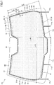
FIG. 1 is a plan view illustrating an example of a configuration of awindow glass 101 for a vehicle. Thewindow glass 101 includes afirst glass plate 11, asecond glass plate 12, a conductor 13, and aterminal part 40. Thewindow glass 101 is an example of a window glass for a vehicle, specifically, an example of a windshield.FIG. 1 illustrates a state where thefirst glass plate 11 and thesecond glass plate 12 overlap with each other, and the conductor 13 is visible transparently through thesecond glass plate 12. - The
first glass plate 11 and thesecond glass plate 12 are transparent or semi-transparent, plate-shaped dielectrics. Thewindow glass 101 is a laminated glass that has thefirst glass plate 11 placed on the side outward from the vehicle, and thesecond glass plate 12 placed on the side inward to the vehicle bonded together via an intermediate film. - Note that the window glass for a vehicle in the embodiment is not limited to such a laminated glass having multiple glass plates bonded together, but may be constituted with a single glass plate, a plate-shaped dielectric, and a conductor placed between the glass plate and the plate-shaped dielectric, or may be constituted with a single glass plate and a conductor placed on the surface of the glass plate.
- The conductor 13 is an example of a conductor placed so as to be extended planarly between the
first glass plate 11 and thesecond glass plate 12. - The conductor 13 is disposed, for example, to be stacked on the surface of the
first glass plate 11 on the side inward to the vehicle compartment or the surface of thesecond glass plate 12 on the side outward from the vehicle compartment (principal surface). If thewindow glass 101 is a laminated glass, the conductor 13 may be placed to be interposed between thefirst glass plate 11 and thesecond glass plate 12 forming the laminated glass, or may be placed to be interposed between the intermediate film and one of the glass plates. - The conductor 13 may be formed by coating a conductive material (for example, silver) applied to the surface of a glass plate by sputtering or the like. Alternatively, the conductor 13 may be formed by coating a conductive material applied to the surface of a resin film (for example, polyethylene terephthalate), which is a member separate from the glass plate, by sputtering or the like. Also, as the conductive material, for example, a zinc oxide film (for example, a zinc oxide film containing gallium (GZO film), an ITO (compound oxide of indium and tin), gold, copper, or the like may be used.
- Although at least a part of the outer edge of the conductor 13 is offset inward on the
first glass plate 11 relative to theglass edges 11a-11d, which are the outer edges of thefirst glass plate 11, the outer edge may be aligned with theglass edges 11a-11d. The conductor 13 has an upperouter edge 13a, a rightouter edge 13b, a lowerouter edge 13c, and a leftouter edge 13d. The conductor 13 has aconcave portion 41 dented along the upperouter edge 13a. Note that the shape of the conductor 13 is not limited to that illustrated in the figure. - The conductor 13 includes an upper bus bar 26, a lower bus bar 27 facing the upper bus bar 26, a right bus bar 24 connected to the right-end part of the upper bus bar 26, a left bus bar 25 connected to the left-end part of the upper bus bar 26, and a
conductive film 51. The upper bus bar 26, the lower bus bar 27, the right bus bar 24, and the left bus bar 25 are examples of strip electrodes, respectively, for applying a DC voltage to theconductive film 51. - The upper bus bar 26 is an example of an upper strip electrode disposed along the upper
outer edge 13a of the conductor 13. The upper bus bar 26 extends along the upperouter edge 13a, and electrically contacts the upper outer edge of theconductive film 51. - The lower bus bar 27 is an example of a lower strip electrode disposed along the lower
outer edge 13c of the conductor 13. The lower bus bar 27 extends along the lowerouter edge 13c, and electrically contacts the lower outer edge of theconductive film 51. - The right bus bar 24 is an example of a right strip electrode having a
gap 28 between itself and a rightouter edge 51b of theconductive film 51, and positioned between the rightouter edge 51b of theconductive film 51 and a rightouter edge 11b of thefirst glass plate 11, in a plan view of thefirst glass plate 11. The rightouter edge 11b is one of the side outer edges of thefirst glass plate 11. The right bus bar 24 is a first side strip electrode that has thegap 28 along the rightouter edge 51b being one of the side outer edges of theconductive film 51, and extends in a vertical direction. The right bus bar 24 does not electrically contact the lower right corner (a right terminal part of the lower bus bar 27) of theconductive film 51, but electrically contacts the upper right corner (a right terminal part of the upper bus bar 26) of theconductive film 51. - The left bus bar 25 is an example of a left strip electrode having a
gap 30 between itself and a leftouter edge 51d of theconductive film 51, and positioned between the leftouter edge 51d of theconductive film 51 and a leftouter edge 11d of thefirst glass plate 11, in a plan view of thefirst glass plate 11. The leftouter edge 11d is another side outer edge of thefirst glass plate 11. The left bus bar 25 is a second side strip electrode that has thegap 30 along the leftouter edge 51d being the other side outer edge of theconductive film 51, and extends in a vertical direction. The left bus bar 25 does not electrically contact the lower left corner (a left terminal part of the lower bus bar 27) of theconductive film 51, but electrically contacts the upper left corner (a left terminal part of the upper bus bar 26) of theconductive film 51. - Note that the plan view of the
first glass plate 11 represents a plan view from the viewpoint for illustratingFIG. 1 , and is synonymous with the plan view of thewindow glass 101. - The
conductive film 51 is a transparent or semi-transparent conductive film. Theconductive film 51 is a conductor in which a current flows when a DC voltage is applied between the pair of the bus bars 26 and 27 to heat thewindow glass 101 so as to be capable of melting snow, melting ice, defogging, and the like on thewindow glass 101. The applications of theconductive film 51 are not limited as such. - In order to apply the DC voltage between the pair of the bus bars 26 and 27 for causing the current to flow in the
conductive film 51, the negative potential side of the DC voltage is connected to the right bus bar 24 and the left bus bar 25 that are electrically connected to the upper bus bar 26, and the higher potential side of the DC voltage is connected to the lower bus bar 27. This makes it possible to apply the DC voltage to theconductive film 51. - For example, in a state where the
window glass 101 is installed in a vehicle, an in-vehicle power supply part is electrically connected to the lower bus bar 27, and a ground part on the vehicle is electrically connected to the right bus bar 24 and the left bus bar 25. The power supply part is, for example, the positive electrode of a DC power supply such as a battery, and the ground part is, for example, the negative electrode of the DC power supply such as a battery, or a body frame (body ground). - On the contrary, in order to apply DC voltage to the
conductive film 51, the higher potential side of the DC voltage may be connected to the right bus bar 24 and the left bus bar 25, and the low potential side of the DC voltage may be connected to the lower bus bar 27. For example, the power supply part is electrically connected to the right bus bar 24 and the left bus bar 25, and the ground part is electrically connected to the lower bus bar 27. - The electric connection structure between the bus bars and the power supply part or the ground part is not limited particularly. For example, if each bus bar is stacked in the laminated glass, the bus bar is electrically connected to the power supply part or the ground part via an electrode extension part such as a copper foil pulled out from the outer edge part of the laminated glass. Alternatively, the power supply part or the ground part may be electrically connected to each bus bar exposed on the surface of the laminated glass.
-
FIG. 1 illustrates examples ofelectrode extraction parts electrode extension part 24a is a conductor extending from the lower end part of the right bus bar 24. Theelectrode extension part 25a is a conductor extending from the lower end part of the left bus bar 25. Theelectrode extension part 27a is a conductor extending from the left part of the lower bus bar 27. The electrode extension part 27b is a conductor extending from the right part of the lower bus bar 27. - The
window glass 101 may include a maskingfilm 60 to mask a part or all of the outer edge part of the conductor 13. The maskingfilm 60 is placed between the conductor 13 and thefirst glass plate 11. This makes it difficult for a part of thewindow glass 101 overlapping the maskingfilm 60 to be seen from the outside of the vehicle in a plan view, and improves the designability of thewindow glass 101. The maskingfilm 60 is, for example, ceramics formed on the surface of thefirst glass plate 11. As an example of the masking film 60a, a baked black ceramic film or the like may be considered. - The masking
film 60 is formed between maskingedges 61 and the glass edges 11a-11d in the plan view of thewindow glass 101. The masking edges 61 are the film edges of the maskingfilm 60. In the case ofFIG. 1 , the maskingfilm 60 masks the upper bus bar 26, the lower bus bar 27, and the upper edge and the lower edge of theconductive film 51. - The
window glass 101 includes aterminal part 40 to electrically connect the right bus bar 24 to a transmission line. Theterminal part 40 can extract a high-frequency current excited in the right bus bar 24, and can output the extracted current to the transmission line. Providing theterminal part 40 as such makes it possible to use the right bus bar 24, which is positioned to have thegap 28 between itself and the rightouter edges 51b of theconductive film 51, as an antenna conductor as it is. Therefore, it is possible to give the function of an antenna to thewindow glass 101 without newly providing an antenna conductor between the rightouter edge 13b of the conductor 13 and the rightouter edge 11b of thefirst glass plate 11. Further, it is not necessary to expand the space between the rightouter edge 13b of the conductor 13 and the rightouter edge 11b of thefirst glass plate 11. Therefore, the degree by which the field of view of a passenger through thewindow glass 101 is blocked by the right bus bar 24 becomes smaller, and the field of view can be secured easily. Moreover, it is possible to avoid a reduced area of theconductive film 51 due to expanding the space, and can secure the area of theconductive film 51 easily. Therefore, it is possible to easily secure the area on which theconductive film 51 can heat thewindow glass 101. - Similarly, the
window glass 101 may include aterminal part 40 to electrically connect the left bus bar 25 to a transmission line. This makes it possible to use the left bus bar 25, which is positioned to have thegap 30 between itself and the leftouter edges 51d of theconductive film 51, as an antenna conductor as it is. Therefore, similar to the case of the right bus bar 24, the field of view of a passenger through thewindow glass 101 and the area of theconductive film 51 can be easily secured. - Using both the right bus bar 24 and the left bus bar 25 as antenna conductors makes it is possible, for example, to use an antenna constituted with the right bus bar 24 and the left bus bar 25 as a multiband antenna, a diversity antenna, or a MIMO (Multi-Input Multi-Output) antenna.
- Examples of the transmission line electrically connected to the
terminal part 40 include a coaxial cable, a microstrip line, a strip line, a coplanar waveguide with a ground plane (a coplanar waveguide having a ground plane placed on the surface opposite to the conductive surface where signal wires are formed), and a coplanar strip line. One end of the transmission line is connected to theterminal part 40, and the other end of the transmission line is connected to a receiver. - In
FIG. 1 , although theterminal part 40 is positioned above the central part of the right bus bar 24 in a vertical direction, the position is not limited as such. Theterminal part 40 just needs to be placed in the neighborhood of the right bus bar 24, taking the length of the transmission line connected to theterminal part 40, the installed position of the receiver, and the like into consideration. - In the embodiment, L16 is 230 mm and L24 is 690 mm. L16 represents the direct distance from the upper-end part of the right bus bar 24 to the
terminal part 40, and L24 represents the direct distance from the upper-end part of the right bus bar 24 to the extended line of the lower bus bar 27. The upper-end part of the right bus bar 24 almost overlaps the upper flange end of the window frame of the vehicle to which thewindow glass 101 is attached, and the extended line of the lower bus bar 27 almost overlaps the lower flange end of the window frame. - Also, it is preferable that the negative potential side of the DC voltage (for example, a ground part) is connected to the right bus bar 24 and the left bus bar 25. This makes it possible to prevent a high-frequency noise generated in the power supply part from propagating to the right bus bar 24 and the left bus bar 25 functioning as the antenna conductors.
- Further, since the
terminal part 40 electrically connects the transmission line to the right bus bar 24 and the left bus bar 25 extending in the vertical direction, it is advantageous to receiving a vertically polarized radio wave. - In the case of
FIG. 1 , theterminal part 40 has a planar electrode 16 (simply referred to as an "electrode 16", below) that faces the right bus bar 24, having thesecond glass plate 12 interposed between theelectrode 16 and the right bus bar 24. The transmission line is electrically connected to theelectrode 16. Since theelectrode 16 faces the right bus bar 24 having the second glass plate 12 (a dielectric) interposed between theelectrode 16 and the right bus bar 24, theelectrode 16 forms a capacitive coupling (an electrostatic coupling) with the right bus bar 24. Therefore, the transmission line electrically connected to theelectrode 16 is electrically connected to the right bus bar 24 by the electrostatic coupling. - The electric power is fed via the
electrode 16 to the right bus bar 24 functioning as the antenna conductor. The right bus bar 24 functions as a monopole antenna having theelectrode 16 as an electrode, which is a unipolar type antenna. This is the same for the left bus bar 25. The signal wire of the transmission line such as a coaxial cable is electrically connected to theelectrode 16, and the ground line of the transmission line such as a coaxial cable is electrically connected to the body frame (a ground part). - In
FIG. 1 , the forms (shapes, size, etc.) of the bus bars and the electrodes just need to be set to satisfy the required value of the antenna gain required for receiving a radio wave in a frequency band to be received by the bus bars. For example, if the frequency band to be received by the bus bars is the digital terrestrial television broadcasting band of 470-770 MHz, the bus bars and the like are formed to be suitable for receiving radio waves in the digital terrestrial television broadcasting band of 470-770 MHz. - If a coaxial cable is used as a power feeder (a transmission line) for feeding electric power to the bus bar via the
electrode 16, for example, the internal conductor of the coaxial cable is electrically connected to theelectrode 16, and the external conductor of the coaxial cable is electrically connected to the body frame (a ground part). Also, a configuration may be adopted in which a connector is mounted on theelectrode 16 for electrically connecting theelectrode 16 to the transmission line such as a coaxial cable. Such a connector makes it easier to attach the signal wire of the transmission line to theelectrode 16. Further, theelectrode 16 may be configured to have a conductive member having a projecting shape (an example of the transmission line) is provided on theelectrode 16 so that the conductive member having the projecting shape contacts and fits in the electric supply part disposed on the flange part of the body to which the window glass is attached. - The shape of the
electrode 16 is determined in consideration of the shape of the conductive member or the mounting surface of the connector and the like. For example, a polygon or a rectangular shape, such as a square, an approximate square, a rectangle, and an approximate rectangle are preferable in terms of packaging. Note that a circular shape, such as a circle, an approximate circle, an ellipse, and an approximate ellipse may be adopted. - Also, the
electrode 16 is formed of, for example, a paste containing a conductive metal such as a silver paste, which is printed on the surface of thesecond glass plate 12 on the side inward to the vehicle, and baked. However, the method of forming is not limited as such, but a string-shaped object or a foil-shaped object made of a conductive substance such as copper may be formed on the surface of thesecond glass plate 12 on the side inward to the vehicle, or bonded to the surface of thesecond glass plate 12 by an adhesive or the like. -
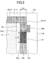
FIG. 2 is a plan view partially illustrating an example of a configuration of thewindow glass 101.FIG. 2 illustrates an expanded view of the right bus bar 24. The following description is applicable to the left bus bar 25. - The right bus bar 24 may have a
slot 24c, which is a cutout without having an open end in the conductor part of the right bus bar 24, and may have a widenedpart 24b, which is a part of the right bus bar 24 whose width in the lateral direction of the right bus bar 24 is increased toward the rightouter edge 11b of thefirst glass plate 11. Providing theslot 24c or thewidened part 24b makes it possible to adjust the resonance frequency of the right bus bar 24 functioning as an antenna conductor. - It is preferable that the
electrode 16 does not overlap theconductive film 51 in the plan view of thefirst glass plate 11. If theelectrode 16 overlaps theconductive film 51 in the plan view of thefirst glass plate 11, the electrostatic coupling between theelectrode 16 and theconductive film 51 becomes stronger, whereas the electrostatic coupling of theelectrode 16 and the right bus bar 24 becomes weaker. Consequently, the antenna gain of the right bus bar 24 functioning as an antenna conductor may drop. Therefore, by placing theelectrode 16 so as not to overlap theconductive film 51 in the plan view of thefirst glass plate 11, it is possible to prevent the antenna gain from dropping. Note that if the drop of the antenna gain is allowed within a permissible range, just a part of theelectrode 16 may overlap theconductive film 51 in the plan view of thefirst glass plate 11. - It is preferable that the area where the
electrode 16 overlaps the right bus bar 24 in the plan view of the first glass plate 11 (referred to as the "area S", below) is contained within a range not protruding out of the outer edge of the first glass plate 11 (for example, the upper limit of the area S is 10000 mm2 or less), and is greater than or equal to 25 mm2, and more preferably, greater than or equal to 200 mm2. It is furthermore preferable that the area S is greater than or equal to 300 mm2 as long as it is within the range. Even if the area S is less than 25 mm2 or less than 200 mm2, a sufficient antenna gain may be obtained in the frequency band of the digital terrestrial television broadcasting depending on the shape of the right bus bar 24. On the other hand, the area S greater than or equal to 200 mm2 or more preferably greater than or equal to 300 mm2 improves not only the antenna gain in the frequency band of the digital terrestrial television broadcasting, but also the antenna gain in the frequency band of band III (band 3) of Digital Audio Broadcasting (DAB). The frequency band of the digital terrestrial television broadcasting is 470-770 MHz. The frequency band of the band 3 is 174-240 MHz. - It is preferable that the electrostatic capacitance C between the
electrode 16 and the right bus bar 24 is greater than or equal to 1 pF and less than or equal to 300 pF, or more preferably, greater than or equal to 6 pF and less than or equal to 80 pF. Even if the electrostatic capacitance C is less than 1 pF or less than 6 pF, a sufficient antenna gain may be obtained in the frequency band of the digital terrestrial television broadcasting depending on the shape of the right bus bar 24. On the other hand, the electrostatic capacitances C greater than or equal to 6 pF or more preferably greater than or equal to 9 pF improves not only the antenna gain in the frequency band of the digital terrestrial television broadcasting, but also the antenna gain in the frequency band of the band 3. - Note that the electrostatic capacitance C is represented by

electrode 16 overlaps the right bus bar 24 in the plan view of thefirst glass plate 11. - If εr is 7.0, d is 2 mm, and the area S is 25 mm2, 200 mm2, 300 mm2, 2500 mm2, or 10000 mm2, then, the electrostatic capacitance C is about 1 pF, about 6 pF, about 9 pF, about 80 pF, or about 300 pF, respectively.
- It is preferable that the
entire electrode 16 overlaps the right bus bar 24 in the plan view of thefirst glass plate 11 as illustrated in the figure. This makes the area S larger than in a case where a part of theelectrode 16 overlaps the right bus bar 24, and hence, the antenna gain of the right bus bar 24 functioning as an antenna conductor improves more. Also, since theelectrode 16 does not protrude out of the right bus bar 24 to be seen in the plan view, the appearance also improves. -
FIG. 3 is a plan view partially illustrating another example of a configuration of thewindow glass 101. As illustrated inFIG. 3 , the upper bus bar 26 may be connected to anintermediate part 24f of the right bus bar 24 instead of being connected to the upper-end part of the right bus bar 24. Theintermediate part 24f protrudes toward theconductive film 51 over thegap 28. Theintermediate part 24f protrudes, for example, in the lateral direction from a part facing theelectrode 16 of the right bus bar 24. -
FIGs. 4-6 illustrate variations of forms of stacking layers included in the window glass according to the embodiment has.FIGs. 4-6 are cross-sectional views in a cross section A-A designated inFIG. 1 . InFIGs. 4-6 , the conductor 13 (theconductive film 51 and right bus bar 24) is placed between thefirst glass plate 11 and the dielectric (thesecond glass plate 12 or a dielectric substrate 33). - In the case of
FIG. 4 and FIG. 5 , the conductor 13 and anintermediate film 14 are placed between thefirst glass plate 11 and thesecond glass plate 12. Thefirst glass plate 11 and thesecond glass plate 12 are joined by theintermediate film 14. Theintermediate film 14 is made of, for example, thermoplastic polyvinyl butyral. The relative permittivity εr of theintermediate film 14 is greater than or equal to 2.8 and less than or equal to 3.0, which is the relative permittivity of a common intermediate film of a laminated glass, for example. - In
FIG. 4 , theelectrode 16 is formed by printing on a surface of thesecond glass plate 12 on the side inward to the vehicle (a surface on the side opposite to the first glass plate 11). The conductor 13 is coated on a surface of thesecond glass plate 12 on the side of thefirst glass plate 11 by vapor deposition. Theelectrode 16 faces the right bus bar 24 having thesecond glass plate 12 being the dielectric interposed in-between. This forms a capacitive coupling between theelectrode 16 and the right bus bar 24, and hence, theelectrode 16 is electrically connected to the right bus bar 24. - The capacitive coupling between the
electrode 16 and the right bus bar 24 of the conductor 13 filters noise in the frequency band where the capacitive coupling is not formed. Therefore, it is possible to control the noise in the conductor 13. This is the same for another form of stacking layers (FIG. 6 ) as will be described later. - In
FIG. 4 , theterminal part 40 has theelectrode 16 and aconnector 201. An end of the transmission line such as a coaxial cable is connected to theconnector 201. Connecting the end of the transmission line to theconnector 201 makes the signal wire of the transmission line connected to theelectrode 16 via asignal lead 202, and the ground line of the transmission line is connected to abody flange 162 via aground lead 203. Thebody flange 162 is a part of the body frame (a ground part). Theconnector 201 may have a configuration to be mountable on theelectrode 16. Thesecond glass plate 12 and thebody flange 162 are bonded by aseal 15. Theelectrode 16 is covered by aninterior panel 29 to improve the appearance. - In
FIG. 5 , a part of thesignal lead 202 is enclosed between thefirst glass plate 11 and thesecond glass plate 12. The right bus bar 24 is connected to an end 202a of thesignal lead 202, and via thesignal lead 202, connected to theconnector 201 outside of thewindow glass 101. - As illustrated in
FIG. 6 , the window glass for a vehicle according to the embodiment may not be a laminated glass. In this case, the dielectric does not need to have the same size as thefirst glass plate 11, and may be a dielectric substrate or the like having a size on which theelectrode 16 can be formed. In the case ofFIG. 6 , the conductor 13 is placed between thefirst glass plate 11 and thedielectric substrate 33. - The
dielectric substrate 33 is, for example, a substrate made of resin. Theelectrode 16 is disposed on thedielectric substrate 33. Thedielectric substrate 33 may be a printed circuit board made of resin having theelectrode 16 printed (for example, a glass epoxy board of FR4 to which a copper foil is attached). -
FIG. 6 illustrates a form in which thefirst glass plate 11 has the conductor 13 coated by vapor deposition, on the surface of thefirst glass plate 11 on the side facing thedielectric substrate 33. The conductor 13, thefirst glass plate 11, and thedielectric substrate 33 are bonded by anadhesion layer 38. -
FIG. 7 is a diagram illustrating an example of a model of thewindow glass 101 on a computer. Amodel body 10 represents a perfect conductor that models the body of a vehicle to which thewindow glass 101 is attached. A modelconductive film 151 is a perfect conductor that models theconductive film 51. Model bus bars 124-127 are perfect conductors that model the right bus bar 24, the left bus bar 25, the upper bus bar 26, and the lower bus bar 27, respectively. Modelelectrode extraction parts electrode extraction parts electrode extraction parts model body 10. Therefore, the modelconductive film 151, the model bus bars 124-127, and the modelelectrode extraction parts model body 10. Amodel electrode 116 is a perfect conductor that models theelectrode 16. The form of stacked layers is the same as inFIG. 4 . - In
FIG. 7 , relevant dimensions are assumed as follows by the unit of mm: - L1: 1950;
- L2: 1300;
- L3: 226; and
- L11 (breadth of the electrode): 10. Also, the breadth of the bus bar shall is also assumed be 10 mm, which is equivalent to L11. Further, the following dimensions are assumed:
- The thickness of the glass plate: 2.0 mm;
- The relative permittivity of the glass plate: 7.0
- The thickness of the intermediate film per sheet: 0.76 mm (30 mil);
- The sheet resistance of the conductive film: 1.0 Ω;
- The thickness of the conductive film: 0.01 mm;
- The thickness of the electrode: 0.01 mm.
- For the window glass having the numerical values set as such, the average of the antenna gain is calculated for every 10 Hz in a range of 170-240 MHz being the frequency band of the band 3 by an electromagnetic field simulation based on an FDTD method (Finite-Difference Time-Domain method). In the simulation, the antenna gain is calculated in a state where the entire model of
FIG. 7 is tilted 25° with respect to the horizontal plane as in the case of an actual windshield. -
FIG. 8 illustrates a simulation result of a relationship between the antenna gain and the area S where themodel electrode 116 overlaps themodel bus bar 124, when the vertical length L12 of themodel electrode 116 is changed from 10 mm to 60 mm. The vertical axis represents the average of the antenna gain measured for every 10 Hz in 170-240 MHz being the frequency band of the band 3. As illustrated inFIG. 8 , the antenna gain in the frequency band of the band 3 improves if the area S is greater than or equal to 200 mm2 (corresponding to the electrostatic capacitance C of 6 pF), or more preferably, greater than or equal to 300 mm2 (corresponding to the electrostatic capacitance C of 9 pF). -
FIGs. 9-13 illustrate actual measurement results of the antenna gain and the reflective coefficient S11 of the bus bar functioning as an antenna conductor, in a state where thewindow glass 101 is attached to the front window frame of an actual vehicle. The form of stacked layers is the same as inFIG. 4 . The conductor 13 is modeled by a copper foil stuck on thewindow glass 101. - The reflective coefficient and antenna gain are actually measured in a state where the
window glass 101 is attached to the window frame of a vehicle on a turntable, and has the part corresponding to theelectrode 16 tilted by about 25° with respect to the horizontal plane. A connector is attached to theelectrode 16 to be connected to the internal conductor of a coaxial cable, and theelectrode 16 is connected to a network analyzer via the coaxial cable. The turntable is rotated so that the window glass receives in every direction a radio wave horizontally emitted. - The antenna gain is measured by setting the center of the vehicle having the
window glass 101 attached at the center of the turntable, and rotating the turntable by 360°. Data of the antenna gain is measured for each rotational angle incremented by 1°, and for every 1.12 MHz in a frequency range of 100-230 MHz, or for every 2.27 MHz in a frequency range of 230-900 MHz. - The elevation angle between the antenna and the position at which the radio wave is emitted is assumed to be in a virtually horizontal direction (i.e., assuming that an elevation angle equal to 0° corresponds to a plane parallel to the ground, and an elevation angle equal to 90° corresponds to the direction toward the zenith, the direction here corresponds to the elevation angle equal to 0°). The measurement of the antenna gain is normalized with respect to a perfect nondirectional antenna as the reference where the antenna gain of the perfect nondirectional antenna is set to 0 dBi.
-
FIG. 9 is a diagram illustrating an example of an actual measurement result of S11 when the area S where theelectrode 16 overlaps the right bus bar 24 is 200 mm2. As illustrated inFIG. 9 , matching is obtained in the frequency band of the digital terrestrial television broadcasting. -
FIG. 10 is a diagram illustrating an example of an actual measurement result of the antenna gain when the area S where theelectrode 16 overlaps the right bus bar 24 is 200 mm2. As illustrated inFIG. 10 , a sufficient antenna gain is obtained in the frequency band of the digital terrestrial television broadcasting. In particular, a higher characteristic is obtained for the antenna gain for a vertically polarized wave than for the antenna gain for a horizontally polarized, in the entire frequency band on average. - Note that for the measurement results in
FIG. 9 andFIG. 10 , relevant dimensions are assumed as follows by the unit of mm: - L16 (see
FIG. 1 ): 230:
L24 (seeFIG. 1 ): 690; - L33 (see
FIG. 1 ): 1491; - L40 (see
FIG. 1 ): 825; - L11 (see
FIG. 2 ): 10; - L12 (see
FIG. 2 ): 20; - L21 (see
FIG. 2 ): 12; and -
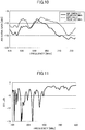
FIG. 11 is a diagram illustrating an example of an actual measurement result of S11 when the area S where theelectrode 16 overlaps the right bus bar 24 is 600 mm2. As illustrated inFIG. 11 , matching is obtained not only in the frequency band of the digital terrestrial television broadcasting, but also in the frequency band of the band 3. -
FIG. 12 is a diagram illustrating an example of an actual measurement result of the antenna gain when the area S where theelectrode 16 overlaps the right bus bar 24 is 600 mm2. As illustrated inFIG. 12 , a sufficient antenna gain is obtained in the frequency band of the digital terrestrial television broadcasting. In particular, a higher characteristic is obtained for the antenna gain for a vertically polarized wave than for the antenna gain for a horizontally polarized, in the entire frequency band on average. -
FIG. 13 is a diagram illustrating an example of an actual measurement result of the antenna gain when the area S where theelectrode 16 overlaps the right bus bar 24 is 600 mm2. As illustrated inFIG. 13 , a sufficient antenna gain is obtained in the frequency band of the band 3. In particular, a higher characteristic is obtained for the antenna gain for a vertically polarized wave than for the antenna gain for a horizontally polarized, in the entire frequency band on average. - Note that for the measurement results in
FIG. 11 to FIG. 13 , relevant dimensions in the unit of mm are the same as inFIG. 9 andFIG. 10 except for L12 (seeFIG. 2 ) being 60. - So far, the window glass and the antenna for a vehicle have been described with the embodiments. Note that the present invention is not limited to the above embodiments. Various modifications and improvements can be made within the scope of the present invention, by combining and/or replacing a part of or all of an embodiment with the others.
- For example, the bus bars may be provided on all four outer edges of the conductor at the top, bottom, right, and left, may be provided only on two outer edges the conductor at the right and left, or may be provided only in the two outer edges of the conductor at the top and bottom. Also, the bus bar may be provided on only three outer edges of the conductor at the top, right, and left, or may be provided on only three outer edges of the conductor at the bottom, right, and left.
- For example, in
FIG. 1 , theterminal part 40 may be positioned at the central part of the right bus bar 24 or the left bus bar 25 in the vertical direction, or may be positioned lower than the central part. - For example, in
FIG. 2 , although theslot 24c and thewidened part 24b are provided in the neighborhood of theelectrode 16, they may be provided away from theelectrode 16. Thewidened part 24b may be widened inward to the first glass plate 11 (for example, in the case ofFIG. 2 , toward the side opposite to the rightouter edge 11b). - For example, the present invention is applicable not only to a form in which the vertical bus bar (the right bus bar or the left bus bar) is electrically connected to the transmission line via the terminal part, but also to a form in which a horizontal bus bar (the upper bus bar or the lower bus bar) is electrically connected to the transmission line via the terminal part. For example, in
FIG. 1 , it is possible to have the upper bus bar 26 connected to the transmission line function as an antenna conductor by providing a gap between the upper bus bar 26 and the upper edge of theconductive film 51. Alternatively, it is possible to have the lower bus bar 27 connected to the transmission line function as an antenna conductor by providing a gap between the lower bus bar 27 and the upper edge of theconductive film 51. Note that even if a gap is provided between the upper bus bar 26 or the lower bus bar 27 and theconductive film 51, a voltage can be applied to theconductive film 51, naturally. -
FIG. 14 illustrates a modified example of the form illustrated inFIG. 1 , to illustrate an example of a form including theterminal part 40 for electrically connecting the upper bus bar 226 to the transmission line. Although thegap 28 exists between the right bus bar 24 and the rightouter edge 51b of theconductive film 51, and thegap 30 exists between theleft bus bar 25 and 51d of the left outer edges of theconductive film 51 inFIG. 1 , nogap FIG. 14 . InFIG. 14 , agap 228 exists between an upper bus bar 226 and an upper outer edge 51a of theconductive film 51. - In
FIG. 14 , the right bus bar 224 electrically contacts the right outer edge of theconductive film 51, the left bus bar 225 electrically contacts the left outer edge of theconductive film 51, and the lower bus bar 27 electrically contacts the lower outer edge of theconductive film 51. - The upper bus bar 226 is an example of an upper strip electrode that has the
gap 228 between itself and the upper outer edges 51a of theconductive film 51, and is positioned between the upper outer edge 51a of theconductive film 51, and the upperouter edge 11a of thefirst glass plate 11 in the plan view of thefirst glass plate 11. The upperouter edge 11a is one of the outer edges of thefirst glass plate 11 on the upside. The upper bus bar 226 extends in the lateral direction, having thegap 228 along the upper outer edge 51a, which is the upper outer edge of theconductive film 51. One end of the upper bus bar 226 electrically contacts the upper terminal part of the right bus bar 224. Theterminal part 40 is as described above.
Claims (9)
- A window glass for a vehicle, comprising:a glass plate; anda conductor placed on a surface of the glass plate,wherein the conductor includes a conductive film and a strip electrode for applying a DC voltage to the conductive film,wherein the strip electrode is formed to have a gap between the strip electrode and an outer edge of the conductive film, and is positioned between the outer edge of the conductive film and an outer edge of the glass plate in a plan view of the glass plate,wherein the window glass for the vehicle includes a terminal part for electrically connecting the strip electrode to a transmission line.
- The window glass for the vehicle as claimed in claim 1, wherein the terminal part includes a planar electrode facing the strip electrode, having a dielectric interposed between the terminal part and the strip electrode.
- The window glass for the vehicle as claimed in claim 2, wherein the planar electrode does not overlap the conductive film in the plan view of the glass plate.
- The window glass for the vehicle as claimed in claim 2 or 3, wherein an entirety of the planar electrode overlaps the strip electrode in the plan view of the glass plate.
- The window glass for the vehicle as claimed in claim 2, wherein only a part of the planar electrode overlaps the conductive film in the plan view of the glass plate.
- The window glass for the vehicle as claimed in any one of claims 2 to 5, wherein an area where the planar electrode overlaps the strip electrode in the plan view of the glass plate is greater than or equal to 25 mm2, and the area is contained within a range not protruding out of the outer edge of the glass plate.
- The window glass as claimed in any one of claims 2 to 5, wherein an electrostatic capacitance between the planar electrode and the strip electrode is greater than or equal to 1 pF and less than or equal to 300 pF.
- The window glass for the vehicle as claimed in any one of claims 1 to 7, wherein the strip electrode is positioned between a side outer edge of the conductive film and a side outer edge of the glass plate in the plan view of the glass plate.
- The window glass for the vehicle as claimed in any one of claims 1 to 8, wherein the strip electrode is an electrode connected to a negative potential side of the DC voltage.
Applications Claiming Priority (1)
| Application Number | Priority Date | Filing Date | Title |
|---|---|---|---|
| JP2016103690A JP6743486B2 (en) | 2016-05-24 | 2016-05-24 | Vehicle window glass |
Publications (2)
| Publication Number | Publication Date |
|---|---|
| EP3249745A1 true EP3249745A1 (en) | 2017-11-29 |
| EP3249745B1 EP3249745B1 (en) | 2020-01-01 |
Family
ID=58992607
Family Applications (1)
| Application Number | Title | Priority Date | Filing Date |
|---|---|---|---|
| EP17170117.0A Active EP3249745B1 (en) | 2016-05-24 | 2017-05-09 | Window glass for vehicle |
Country Status (4)
| Country | Link |
|---|---|
| US (1) | US10638548B2 (en) |
| EP (1) | EP3249745B1 (en) |
| JP (1) | JP6743486B2 (en) |
| CN (1) | CN107453029B (en) |
Cited By (1)
| Publication number | Priority date | Publication date | Assignee | Title |
|---|---|---|---|---|
| EP3528338A1 (en) * | 2018-02-20 | 2019-08-21 | AGC Automotive Americas R & D, Inc. | Window assembly comprising conductive transparent layer and conductive element implementing hybrid bus-bar/antenna |
Families Citing this family (5)
| Publication number | Priority date | Publication date | Assignee | Title |
|---|---|---|---|---|
| EP3741000B1 (en) * | 2018-03-05 | 2023-08-30 | Pittsburgh Glass Works, LLC | Window assembly with heating and antenna functions |
| JPWO2020230679A1 (en) * | 2019-05-13 | 2020-11-19 | ||
| US11515614B2 (en) | 2019-11-22 | 2022-11-29 | Pittsburgh Glass Works, Llc | Heatable vehicle glazing with antennas |
| CN111605385A (en) * | 2020-06-11 | 2020-09-01 | 福耀玻璃工业集团股份有限公司 | Window assembly for vehicle and vehicle |
| WO2022039020A1 (en) * | 2020-08-19 | 2022-02-24 | Agc株式会社 | Vehicle window glass |
Citations (4)
| Publication number | Priority date | Publication date | Assignee | Title |
|---|---|---|---|---|
| US20030019859A1 (en) * | 2001-03-26 | 2003-01-30 | Jean-Marc Sol | Method of attaching bus bars to a conductive coating for a heatable vehicle window |
| JP2003211956A (en) | 2002-01-25 | 2003-07-30 | Nippon Sheet Glass Co Ltd | Laminated glass for windshield |
| JP2012023603A (en) | 2010-07-15 | 2012-02-02 | Central Glass Co Ltd | Glass antenna for vehicle |
| US20150207203A1 (en) * | 2014-01-22 | 2015-07-23 | Agc Flat Glass North America, Inc. | Window assembly with transparent layer and an antenna element |
Family Cites Families (47)
| Publication number | Priority date | Publication date | Assignee | Title |
|---|---|---|---|---|
| US4021813A (en) * | 1974-07-01 | 1977-05-03 | The United States Of America As Represented By The Secretary Of The Navy | Geometrically derived beam circular antenna array |
| GB8402244D0 (en) * | 1984-01-27 | 1984-02-29 | Pilkington Brothers Plc | Glass window |
| US5324374A (en) * | 1988-07-27 | 1994-06-28 | Saint Gobain Vitrage | Laminated glass with an electroconductive layer |
| GB2227908B (en) * | 1988-11-23 | 1993-12-08 | Gen Electric Co Plc | Radio receiver antenna systems |
| US5266960A (en) * | 1989-05-01 | 1993-11-30 | Fuba Hans Kolbe Co. | Pane antenna having at least one wire-like antenna conductor combined with a set of heating wires |
| US5198826A (en) * | 1989-09-22 | 1993-03-30 | Nippon Sheet Glass Co., Ltd. | Wide-band loop antenna with outer and inner loop conductors |
| JPH0543608U (en) * | 1991-11-05 | 1993-06-11 | 日本板硝子株式会社 | Window glass antenna device |
| US5307076A (en) * | 1991-11-05 | 1994-04-26 | Nippon Sheet Glass Co., Ltd. | Window glass antenna device |
| EP0562607B1 (en) * | 1992-03-27 | 1999-09-08 | Asahi Glass Company Ltd. | A diversity glass antenna for an automobile |
| US5610618A (en) * | 1994-12-20 | 1997-03-11 | Ford Motor Company | Motor vehicle antenna systems |
| US5739794A (en) * | 1995-05-22 | 1998-04-14 | General Motors Corporation | Vehicle window antenna with parasitic slot transmission line |
| GB2335081B (en) * | 1998-03-05 | 2002-04-03 | Nec Technologies | Antenna for mobile telephones |
| US6239758B1 (en) * | 2000-01-24 | 2001-05-29 | Receptec L.L.C. | Vehicle window antenna system |
| JP2002020142A (en) * | 2000-06-29 | 2002-01-23 | Nippon Sheet Glass Co Ltd | Windshield for vehicle and method for manufacturing the same |
| JP2003176154A (en) * | 2001-12-06 | 2003-06-24 | Asahi Glass Co Ltd | Electric-heating glass |
| JP2005012588A (en) * | 2003-06-20 | 2005-01-13 | Nippon Sheet Glass Co Ltd | Glass antenna system for vehicle |
| US7223939B2 (en) * | 2004-11-12 | 2007-05-29 | Agc Automotive Americas, R & D, Inc. | Electrical connector for a window pane of a vehicle |
| CN101185383B (en) * | 2005-01-10 | 2011-03-30 | 弯曲的路径Emi解决方案有限责任公司 | Three-dimensional configurations providing electromagnetic interference shielding for electronics enclosures |
| US7335421B2 (en) * | 2005-07-20 | 2008-02-26 | Ppg Industries Ohio, Inc. | Heatable windshield |
| WO2007028448A1 (en) * | 2005-07-21 | 2007-03-15 | Fractus, S.A. | Handheld device with two antennas, and method of enhancing the isolation between the antennas |
| US7289073B2 (en) * | 2005-08-19 | 2007-10-30 | Gm Global Technology Operations, Inc. | Method for improving the efficiency of transparent thin film antennas and antennas made by such method |
| DE102006039357B4 (en) * | 2005-09-12 | 2018-06-28 | Heinz Lindenmeier | Antenna diversity system for radio reception for vehicles |
| JP2007195153A (en) * | 2006-01-16 | 2007-08-02 | Samsung Electro-Mechanics Co Ltd | Wideband chip antenna |
| US20080028697A1 (en) * | 2006-08-04 | 2008-02-07 | Chengtao Li | Window defroster assembly with light control |
| MX2009006781A (en) * | 2006-12-21 | 2010-01-15 | Neology Inc | Systems and methods for a rfid enabled metal license plate. |
| DE102007011636A1 (en) * | 2007-03-09 | 2008-09-11 | Lindenmeier, Heinz, Prof. Dr. Ing. | Antenna for radio reception with diversity function in a vehicle |
| US20110175791A1 (en) * | 2008-09-19 | 2011-07-21 | Delphi Technologies, Inc. | Multi-beam, polarization diversity narrow-band cognitive antenna |
| JP5655782B2 (en) * | 2009-07-09 | 2015-01-21 | 旭硝子株式会社 | Vehicle window glass and antenna |
| DE102009026378A1 (en) * | 2009-08-14 | 2011-02-17 | Saint-Gobain Sekurit Deutschland Gmbh & Co. Kg | Disc with electrically conductive structures |
| US8120543B2 (en) * | 2009-10-19 | 2012-02-21 | Oleksandr Sulima | Transmission line slot antenna |
| EP2405708A1 (en) * | 2010-07-07 | 2012-01-11 | Saint-Gobain Glass France | Transparent plate with heatable coating |
| US8576130B2 (en) * | 2010-10-22 | 2013-11-05 | Pittsburgh Glass Works, Llc | Wideband antenna |
| US8466842B2 (en) * | 2010-10-22 | 2013-06-18 | Pittsburgh Glass Works, Llc | Window antenna |
| WO2012079040A1 (en) * | 2010-12-09 | 2012-06-14 | Agc Automotive Americas R&D, Inc. | Window assembly having a transparent layer with a slot for a transparent antenna element |
| KR101268841B1 (en) * | 2011-11-04 | 2013-05-29 | 브로콜리 주식회사 | Augmented antenna |
| WO2014019780A1 (en) * | 2012-08-01 | 2014-02-06 | Saint-Gobain Glass France | Composite pane with electrical contact-making means |
| US20160174420A1 (en) * | 2013-03-15 | 2016-06-16 | Paul Douglas Cochrane | Formed channels providing electromagnetic shielding in electronics |
| CN105075009B (en) * | 2013-03-27 | 2017-08-22 | 旭硝子株式会社 | Window glass for vehicle and antenna |
| GB201309549D0 (en) * | 2013-05-29 | 2013-07-10 | Pilkington Group Ltd | Glazing |
| CN105431977B (en) * | 2013-08-02 | 2018-01-23 | 旭硝子株式会社 | Antenna system |
| WO2015019904A1 (en) * | 2013-08-05 | 2015-02-12 | 旭硝子株式会社 | Antenna device |
| MX2019004815A (en) * | 2014-05-30 | 2022-05-06 | Lutron Tech Co Llc | Wireless control device. |
| US9652979B2 (en) * | 2014-05-30 | 2017-05-16 | Lutron Electronics Co., Inc. | Wireless control device |
| GB2528899B (en) * | 2014-08-04 | 2019-12-04 | Ford Global Tech Llc | An electrically heated laminated window |
| KR102226173B1 (en) * | 2014-09-02 | 2021-03-10 | 삼성전자주식회사 | Antenna using exterior metal frame and electronic device therewith |
| KR102314790B1 (en) * | 2015-02-26 | 2021-10-20 | 삼성전자주식회사 | Electronic device including antenna device |
| WO2016198914A1 (en) * | 2015-06-09 | 2016-12-15 | Assa Abloy Ab | Rifd tag with a tunable antenna |
-
2016
- 2016-05-24 JP JP2016103690A patent/JP6743486B2/en active Active
-
2017
- 2017-05-09 EP EP17170117.0A patent/EP3249745B1/en active Active
- 2017-05-10 US US15/592,105 patent/US10638548B2/en active Active
- 2017-05-22 CN CN201710362850.XA patent/CN107453029B/en active Active
Patent Citations (5)
| Publication number | Priority date | Publication date | Assignee | Title |
|---|---|---|---|---|
| US20030019859A1 (en) * | 2001-03-26 | 2003-01-30 | Jean-Marc Sol | Method of attaching bus bars to a conductive coating for a heatable vehicle window |
| JP2003211956A (en) | 2002-01-25 | 2003-07-30 | Nippon Sheet Glass Co Ltd | Laminated glass for windshield |
| US20030150848A1 (en) * | 2002-01-25 | 2003-08-14 | Nippon Sheet Glass Co., Ltd. | Laminated glass sheet for windshield |
| JP2012023603A (en) | 2010-07-15 | 2012-02-02 | Central Glass Co Ltd | Glass antenna for vehicle |
| US20150207203A1 (en) * | 2014-01-22 | 2015-07-23 | Agc Flat Glass North America, Inc. | Window assembly with transparent layer and an antenna element |
Cited By (2)
| Publication number | Priority date | Publication date | Assignee | Title |
|---|---|---|---|---|
| EP3528338A1 (en) * | 2018-02-20 | 2019-08-21 | AGC Automotive Americas R & D, Inc. | Window assembly comprising conductive transparent layer and conductive element implementing hybrid bus-bar/antenna |
| US10721795B2 (en) | 2018-02-20 | 2020-07-21 | Agc Automotive Americas R&D, Inc. | Window assembly comprising conductive transparent layer and conductive element implementing hybrid bus-bar/antenna |
Also Published As
| Publication number | Publication date |
|---|---|
| JP6743486B2 (en) | 2020-08-19 |
| JP2017210071A (en) | 2017-11-30 |
| CN107453029B (en) | 2021-01-05 |
| CN107453029A (en) | 2017-12-08 |
| US10638548B2 (en) | 2020-04-28 |
| US20170347404A1 (en) | 2017-11-30 |
| EP3249745B1 (en) | 2020-01-01 |
Similar Documents
| Publication | Publication Date | Title |
|---|---|---|
| EP3249745B1 (en) | Window glass for vehicle | |
| US9755300B2 (en) | Windshield and antenna | |
| EP2648276B1 (en) | Window glass and antenna for vehicle | |
| US9509038B2 (en) | Vehicle window glass and antenna | |
| US10211509B2 (en) | Vehicle window glass and antenna | |
| US8941545B2 (en) | Windowpane for vehicle and antenna | |
| EP2660930B1 (en) | Antenna | |
| WO2014142312A1 (en) | Window glass for vehicle | |
| EP3249743A1 (en) | Window glass for vehicle | |
| US20200194894A1 (en) | Antenna device | |
| JP2003163524A (en) | Film antenna device |
Legal Events
| Date | Code | Title | Description |
|---|---|---|---|
| PUAI | Public reference made under article 153(3) epc to a published international application that has entered the european phase |
Free format text: ORIGINAL CODE: 0009012 |
|
| STAA | Information on the status of an ep patent application or granted ep patent |
Free format text: STATUS: THE APPLICATION HAS BEEN PUBLISHED |
|
| AK | Designated contracting states |
Kind code of ref document: A1 Designated state(s): AL AT BE BG CH CY CZ DE DK EE ES FI FR GB GR HR HU IE IS IT LI LT LU LV MC MK MT NL NO PL PT RO RS SE SI SK SM TR |
|
| AX | Request for extension of the european patent |
Extension state: BA ME |
|
| STAA | Information on the status of an ep patent application or granted ep patent |
Free format text: STATUS: REQUEST FOR EXAMINATION WAS MADE |
|
| 17P | Request for examination filed |
Effective date: 20180322 |
|
| RBV | Designated contracting states (corrected) |
Designated state(s): AL AT BE BG CH CY CZ DE DK EE ES FI FR GB GR HR HU IE IS IT LI LT LU LV MC MK MT NL NO PL PT RO RS SE SI SK SM TR |
|
| RAP1 | Party data changed (applicant data changed or rights of an application transferred) |
Owner name: AGC INC. |
|
| STAA | Information on the status of an ep patent application or granted ep patent |
Free format text: STATUS: EXAMINATION IS IN PROGRESS |
|
| 17Q | First examination report despatched |
Effective date: 20190318 |
|
| RIC1 | Information provided on ipc code assigned before grant |
Ipc: H01Q 1/32 20060101AFI20190729BHEP Ipc: H01Q 1/46 20060101ALI20190729BHEP Ipc: H05B 3/84 20060101ALI20190729BHEP Ipc: B60J 1/20 20060101ALI20190729BHEP Ipc: H01Q 1/12 20060101ALI20190729BHEP Ipc: H05B 3/03 20060101ALI20190729BHEP |
|
| GRAP | Despatch of communication of intention to grant a patent |
Free format text: ORIGINAL CODE: EPIDOSNIGR1 |
|
| STAA | Information on the status of an ep patent application or granted ep patent |
Free format text: STATUS: GRANT OF PATENT IS INTENDED |
|
| INTG | Intention to grant announced |
Effective date: 20190917 |
|
| GRAS | Grant fee paid |
Free format text: ORIGINAL CODE: EPIDOSNIGR3 |
|
| GRAA | (expected) grant |
Free format text: ORIGINAL CODE: 0009210 |
|
| STAA | Information on the status of an ep patent application or granted ep patent |
Free format text: STATUS: THE PATENT HAS BEEN GRANTED |
|
| AK | Designated contracting states |
Kind code of ref document: B1 Designated state(s): AL AT BE BG CH CY CZ DE DK EE ES FI FR GB GR HR HU IE IS IT LI LT LU LV MC MK MT NL NO PL PT RO RS SE SI SK SM TR |
|
| REG | Reference to a national code |
Ref country code: GB Ref legal event code: FG4D |
|
| REG | Reference to a national code |
Ref country code: CH Ref legal event code: EP Ref country code: AT Ref legal event code: REF Ref document number: 1220955 Country of ref document: AT Kind code of ref document: T Effective date: 20200115 |
|
| REG | Reference to a national code |
Ref country code: IE Ref legal event code: FG4D |
|
| REG | Reference to a national code |
Ref country code: DE Ref legal event code: R096 Ref document number: 602017010269 Country of ref document: DE |
|
| REG | Reference to a national code |
Ref country code: NL Ref legal event code: MP Effective date: 20200101 |
|
| REG | Reference to a national code |
Ref country code: LT Ref legal event code: MG4D |
|
| PG25 | Lapsed in a contracting state [announced via postgrant information from national office to epo] |
Ref country code: PT Free format text: LAPSE BECAUSE OF FAILURE TO SUBMIT A TRANSLATION OF THE DESCRIPTION OR TO PAY THE FEE WITHIN THE PRESCRIBED TIME-LIMIT Effective date: 20200527 Ref country code: NL Free format text: LAPSE BECAUSE OF FAILURE TO SUBMIT A TRANSLATION OF THE DESCRIPTION OR TO PAY THE FEE WITHIN THE PRESCRIBED TIME-LIMIT Effective date: 20200101 Ref country code: CZ Free format text: LAPSE BECAUSE OF FAILURE TO SUBMIT A TRANSLATION OF THE DESCRIPTION OR TO PAY THE FEE WITHIN THE PRESCRIBED TIME-LIMIT Effective date: 20200101 Ref country code: LT Free format text: LAPSE BECAUSE OF FAILURE TO SUBMIT A TRANSLATION OF THE DESCRIPTION OR TO PAY THE FEE WITHIN THE PRESCRIBED TIME-LIMIT Effective date: 20200101 Ref country code: NO Free format text: LAPSE BECAUSE OF FAILURE TO SUBMIT A TRANSLATION OF THE DESCRIPTION OR TO PAY THE FEE WITHIN THE PRESCRIBED TIME-LIMIT Effective date: 20200401 Ref country code: FI Free format text: LAPSE BECAUSE OF FAILURE TO SUBMIT A TRANSLATION OF THE DESCRIPTION OR TO PAY THE FEE WITHIN THE PRESCRIBED TIME-LIMIT Effective date: 20200101 Ref country code: RS Free format text: LAPSE BECAUSE OF FAILURE TO SUBMIT A TRANSLATION OF THE DESCRIPTION OR TO PAY THE FEE WITHIN THE PRESCRIBED TIME-LIMIT Effective date: 20200101 |
|
| PG25 | Lapsed in a contracting state [announced via postgrant information from national office to epo] |
Ref country code: IS Free format text: LAPSE BECAUSE OF FAILURE TO SUBMIT A TRANSLATION OF THE DESCRIPTION OR TO PAY THE FEE WITHIN THE PRESCRIBED TIME-LIMIT Effective date: 20200501 Ref country code: GR Free format text: LAPSE BECAUSE OF FAILURE TO SUBMIT A TRANSLATION OF THE DESCRIPTION OR TO PAY THE FEE WITHIN THE PRESCRIBED TIME-LIMIT Effective date: 20200402 Ref country code: HR Free format text: LAPSE BECAUSE OF FAILURE TO SUBMIT A TRANSLATION OF THE DESCRIPTION OR TO PAY THE FEE WITHIN THE PRESCRIBED TIME-LIMIT Effective date: 20200101 Ref country code: LV Free format text: LAPSE BECAUSE OF FAILURE TO SUBMIT A TRANSLATION OF THE DESCRIPTION OR TO PAY THE FEE WITHIN THE PRESCRIBED TIME-LIMIT Effective date: 20200101 Ref country code: SE Free format text: LAPSE BECAUSE OF FAILURE TO SUBMIT A TRANSLATION OF THE DESCRIPTION OR TO PAY THE FEE WITHIN THE PRESCRIBED TIME-LIMIT Effective date: 20200101 Ref country code: BG Free format text: LAPSE BECAUSE OF FAILURE TO SUBMIT A TRANSLATION OF THE DESCRIPTION OR TO PAY THE FEE WITHIN THE PRESCRIBED TIME-LIMIT Effective date: 20200401 |
|
| REG | Reference to a national code |
Ref country code: DE Ref legal event code: R097 Ref document number: 602017010269 Country of ref document: DE |
|
| PG25 | Lapsed in a contracting state [announced via postgrant information from national office to epo] |
Ref country code: DK Free format text: LAPSE BECAUSE OF FAILURE TO SUBMIT A TRANSLATION OF THE DESCRIPTION OR TO PAY THE FEE WITHIN THE PRESCRIBED TIME-LIMIT Effective date: 20200101 Ref country code: EE Free format text: LAPSE BECAUSE OF FAILURE TO SUBMIT A TRANSLATION OF THE DESCRIPTION OR TO PAY THE FEE WITHIN THE PRESCRIBED TIME-LIMIT Effective date: 20200101 Ref country code: SM Free format text: LAPSE BECAUSE OF FAILURE TO SUBMIT A TRANSLATION OF THE DESCRIPTION OR TO PAY THE FEE WITHIN THE PRESCRIBED TIME-LIMIT Effective date: 20200101 Ref country code: ES Free format text: LAPSE BECAUSE OF FAILURE TO SUBMIT A TRANSLATION OF THE DESCRIPTION OR TO PAY THE FEE WITHIN THE PRESCRIBED TIME-LIMIT Effective date: 20200101 Ref country code: RO Free format text: LAPSE BECAUSE OF FAILURE TO SUBMIT A TRANSLATION OF THE DESCRIPTION OR TO PAY THE FEE WITHIN THE PRESCRIBED TIME-LIMIT Effective date: 20200101 Ref country code: SK Free format text: LAPSE BECAUSE OF FAILURE TO SUBMIT A TRANSLATION OF THE DESCRIPTION OR TO PAY THE FEE WITHIN THE PRESCRIBED TIME-LIMIT Effective date: 20200101 |
|
| PLBE | No opposition filed within time limit |
Free format text: ORIGINAL CODE: 0009261 |
|
| STAA | Information on the status of an ep patent application or granted ep patent |
Free format text: STATUS: NO OPPOSITION FILED WITHIN TIME LIMIT |
|
| REG | Reference to a national code |
Ref country code: AT Ref legal event code: MK05 Ref document number: 1220955 Country of ref document: AT Kind code of ref document: T Effective date: 20200101 |
|
| 26N | No opposition filed |
Effective date: 20201002 |
|
| PG25 | Lapsed in a contracting state [announced via postgrant information from national office to epo] |
Ref country code: IT Free format text: LAPSE BECAUSE OF FAILURE TO SUBMIT A TRANSLATION OF THE DESCRIPTION OR TO PAY THE FEE WITHIN THE PRESCRIBED TIME-LIMIT Effective date: 20200101 Ref country code: AT Free format text: LAPSE BECAUSE OF FAILURE TO SUBMIT A TRANSLATION OF THE DESCRIPTION OR TO PAY THE FEE WITHIN THE PRESCRIBED TIME-LIMIT Effective date: 20200101 Ref country code: LI Free format text: LAPSE BECAUSE OF NON-PAYMENT OF DUE FEES Effective date: 20200531 Ref country code: MC Free format text: LAPSE BECAUSE OF FAILURE TO SUBMIT A TRANSLATION OF THE DESCRIPTION OR TO PAY THE FEE WITHIN THE PRESCRIBED TIME-LIMIT Effective date: 20200101 Ref country code: CH Free format text: LAPSE BECAUSE OF NON-PAYMENT OF DUE FEES Effective date: 20200531 |
|
| PG25 | Lapsed in a contracting state [announced via postgrant information from national office to epo] |
Ref country code: PL Free format text: LAPSE BECAUSE OF FAILURE TO SUBMIT A TRANSLATION OF THE DESCRIPTION OR TO PAY THE FEE WITHIN THE PRESCRIBED TIME-LIMIT Effective date: 20200101 Ref country code: SI Free format text: LAPSE BECAUSE OF FAILURE TO SUBMIT A TRANSLATION OF THE DESCRIPTION OR TO PAY THE FEE WITHIN THE PRESCRIBED TIME-LIMIT Effective date: 20200101 |
|
| REG | Reference to a national code |
Ref country code: BE Ref legal event code: MM Effective date: 20200531 |
|
| PG25 | Lapsed in a contracting state [announced via postgrant information from national office to epo] |
Ref country code: LU Free format text: LAPSE BECAUSE OF NON-PAYMENT OF DUE FEES Effective date: 20200509 |
|
| PG25 | Lapsed in a contracting state [announced via postgrant information from national office to epo] |
Ref country code: FR Free format text: LAPSE BECAUSE OF NON-PAYMENT OF DUE FEES Effective date: 20200531 Ref country code: IE Free format text: LAPSE BECAUSE OF NON-PAYMENT OF DUE FEES Effective date: 20200509 |
|
| PG25 | Lapsed in a contracting state [announced via postgrant information from national office to epo] |
Ref country code: BE Free format text: LAPSE BECAUSE OF NON-PAYMENT OF DUE FEES Effective date: 20200531 |
|
| GBPC | Gb: european patent ceased through non-payment of renewal fee |
Effective date: 20210509 |
|
| PG25 | Lapsed in a contracting state [announced via postgrant information from national office to epo] |
Ref country code: GB Free format text: LAPSE BECAUSE OF NON-PAYMENT OF DUE FEES Effective date: 20210509 |
|
| PG25 | Lapsed in a contracting state [announced via postgrant information from national office to epo] |
Ref country code: TR Free format text: LAPSE BECAUSE OF FAILURE TO SUBMIT A TRANSLATION OF THE DESCRIPTION OR TO PAY THE FEE WITHIN THE PRESCRIBED TIME-LIMIT Effective date: 20200101 Ref country code: MT Free format text: LAPSE BECAUSE OF FAILURE TO SUBMIT A TRANSLATION OF THE DESCRIPTION OR TO PAY THE FEE WITHIN THE PRESCRIBED TIME-LIMIT Effective date: 20200101 Ref country code: CY Free format text: LAPSE BECAUSE OF FAILURE TO SUBMIT A TRANSLATION OF THE DESCRIPTION OR TO PAY THE FEE WITHIN THE PRESCRIBED TIME-LIMIT Effective date: 20200101 |
|
| PG25 | Lapsed in a contracting state [announced via postgrant information from national office to epo] |
Ref country code: MK Free format text: LAPSE BECAUSE OF FAILURE TO SUBMIT A TRANSLATION OF THE DESCRIPTION OR TO PAY THE FEE WITHIN THE PRESCRIBED TIME-LIMIT Effective date: 20200101 Ref country code: AL Free format text: LAPSE BECAUSE OF FAILURE TO SUBMIT A TRANSLATION OF THE DESCRIPTION OR TO PAY THE FEE WITHIN THE PRESCRIBED TIME-LIMIT Effective date: 20200101 |
|
| PGFP | Annual fee paid to national office [announced via postgrant information from national office to epo] |
Ref country code: DE Payment date: 20230519 Year of fee payment: 7 |