EP3249356A1 - Systems and methods for a four-mass vibrating mems structure - Google Patents
Systems and methods for a four-mass vibrating mems structure Download PDFInfo
- Publication number
- EP3249356A1 EP3249356A1 EP17162859.7A EP17162859A EP3249356A1 EP 3249356 A1 EP3249356 A1 EP 3249356A1 EP 17162859 A EP17162859 A EP 17162859A EP 3249356 A1 EP3249356 A1 EP 3249356A1
- Authority
- EP
- European Patent Office
- Prior art keywords
- proof
- mems sensor
- substrate
- drive
- proof masses
- Prior art date
- Legal status (The legal status is an assumption and is not a legal conclusion. Google has not performed a legal analysis and makes no representation as to the accuracy of the status listed.)
- Granted
Links
Images



Classifications
-
- G—PHYSICS
- G01—MEASURING; TESTING
- G01C—MEASURING DISTANCES, LEVELS OR BEARINGS; SURVEYING; NAVIGATION; GYROSCOPIC INSTRUMENTS; PHOTOGRAMMETRY OR VIDEOGRAMMETRY
- G01C19/00—Gyroscopes; Turn-sensitive devices using vibrating masses; Turn-sensitive devices without moving masses; Measuring angular rate using gyroscopic effects
- G01C19/56—Turn-sensitive devices using vibrating masses, e.g. vibratory angular rate sensors based on Coriolis forces
- G01C19/5719—Turn-sensitive devices using vibrating masses, e.g. vibratory angular rate sensors based on Coriolis forces using planar vibrating masses driven in a translation vibration along an axis
- G01C19/5733—Structural details or topology
- G01C19/574—Structural details or topology the devices having two sensing masses in anti-phase motion
- G01C19/5747—Structural details or topology the devices having two sensing masses in anti-phase motion each sensing mass being connected to a driving mass, e.g. driving frames
-
- G—PHYSICS
- G01—MEASURING; TESTING
- G01C—MEASURING DISTANCES, LEVELS OR BEARINGS; SURVEYING; NAVIGATION; GYROSCOPIC INSTRUMENTS; PHOTOGRAMMETRY OR VIDEOGRAMMETRY
- G01C19/00—Gyroscopes; Turn-sensitive devices using vibrating masses; Turn-sensitive devices without moving masses; Measuring angular rate using gyroscopic effects
- G01C19/56—Turn-sensitive devices using vibrating masses, e.g. vibratory angular rate sensors based on Coriolis forces
- G01C19/5642—Turn-sensitive devices using vibrating masses, e.g. vibratory angular rate sensors based on Coriolis forces using vibrating bars or beams
- G01C19/5656—Turn-sensitive devices using vibrating masses, e.g. vibratory angular rate sensors based on Coriolis forces using vibrating bars or beams the devices involving a micromechanical structure
-
- G—PHYSICS
- G01—MEASURING; TESTING
- G01C—MEASURING DISTANCES, LEVELS OR BEARINGS; SURVEYING; NAVIGATION; GYROSCOPIC INSTRUMENTS; PHOTOGRAMMETRY OR VIDEOGRAMMETRY
- G01C19/00—Gyroscopes; Turn-sensitive devices using vibrating masses; Turn-sensitive devices without moving masses; Measuring angular rate using gyroscopic effects
- G01C19/56—Turn-sensitive devices using vibrating masses, e.g. vibratory angular rate sensors based on Coriolis forces
- G01C19/5705—Turn-sensitive devices using vibrating masses, e.g. vibratory angular rate sensors based on Coriolis forces using masses driven in reciprocating rotary motion about an axis
- G01C19/5712—Turn-sensitive devices using vibrating masses, e.g. vibratory angular rate sensors based on Coriolis forces using masses driven in reciprocating rotary motion about an axis the devices involving a micromechanical structure
-
- G—PHYSICS
- G01—MEASURING; TESTING
- G01C—MEASURING DISTANCES, LEVELS OR BEARINGS; SURVEYING; NAVIGATION; GYROSCOPIC INSTRUMENTS; PHOTOGRAMMETRY OR VIDEOGRAMMETRY
- G01C19/00—Gyroscopes; Turn-sensitive devices using vibrating masses; Turn-sensitive devices without moving masses; Measuring angular rate using gyroscopic effects
- G01C19/56—Turn-sensitive devices using vibrating masses, e.g. vibratory angular rate sensors based on Coriolis forces
- G01C19/5719—Turn-sensitive devices using vibrating masses, e.g. vibratory angular rate sensors based on Coriolis forces using planar vibrating masses driven in a translation vibration along an axis
- G01C19/5733—Structural details or topology
- G01C19/574—Structural details or topology the devices having two sensing masses in anti-phase motion
Definitions
- MEMS vibratory sensors may be capable of providing high precision measurements.
- MEMS vibratory sensors may consist of one or more proof masses connected to a substrate through flexible suspensions (flexures) such that the MEMS sensor has two resonant modes.
- a velocity induced by driving the proof masses along the first resonant mode (drive mode) produces a Coriolis force on the second mode (sense mode) when the substrate is rotated.
- the resulting displacement of the sense mode at the drive frequency provides an output of the sensor, which is a measure of the rotation rate.
- the output of a force rebalance control loop that nulls the sense mode displacement may also provide a measure of the rotation rate.
- a common sensor output error is bias or zero-rate offset.
- a bias error occurs when the sensor output is non-zero when there is no substrate rotation.
- Systems may be able to compensate for the bias error if the bias is repeatable due to environmental conditions, such as temperature, that vary in a repeatable manner. However, there may be some level of error that is non-compensatable such as bias due to hysteresis or stress relaxation in materials, non-zero thermal time constants, aging of electronics components, or other factors.
- One cause of non-compensatable bias error is due to mechanical coupling of the sensor to a substrate.
- Imperfect fabrication of the sensor which may include imperfect coupling of the sensor and substrate, may cause the driven motion of the drive mode to be asymmetric, producing a net force and/or moment on the substrate.
- the imbalanced force or moment exerted on the substrate can produce motion in structures external to the sensor. This external motion can in turn exert a force and/or moment on the sense mode of the sensor, producing a bias signal at the sensor output. If the external motion and/or the mechanical coupling of the substrate to the sensor has non-repeatable variation over changes in temperature, then the compensated bias of the sensor may not account for the non-repeatable variation.
- Typical two-mass MEMS sensors known to one having skill in the art, have substantial non-compensatable bias because the sense mode motion has net angular momentum.
- sense mode motion can be produced by rotational vibration of the substrate even if the gyroscope is perfectly fabricated.
- a MEMS sensor includes four proof masses, wherein each proof mass is driven such that the proof masses oscillate along radial lines extending from the center of the MEMS sensor through the center of the respective proof mass, each proof mass comprising a plurality of drive combs; and a plurality of sense combs.
- the MEMS sensor includes at least one substrate having one or more drive electrodes for driving the four proof masses along the radial lines at a drive frequency, wherein a resonant frequency of a sense mode is different from the drive frequency.
- a MEMS sensor may include four proof masses that are arranged symmetrically around the center of the MEMS sensing mechanism.
- the four proof masses may be fabricated within a silicon layer, where the four masses are coupled to one another by a series of flexures.
- Each of the proof masses may have mirror symmetry about a line passing through its center of mass and the center of the sensor mechanism.
- the masses are driven to oscillate radially at the drive mode resonant frequency.
- the symmetries of each mass, flexures, and each of its adjacent masses may insure that the drive mode motion of each mass is linear along a line from its center of mass to the center of the sensor mechanism.
- Rotation of the substrate about an axis that extends out of the plane formed by the proof masses in the MEMS sensor at a slowly varying or slowly oscillating rate produces a Coriolis force on each mass.
- the Coriolis force excites sense mode motion of the proof masses that is perpendicular to the drive mode motion.
- the sense mode motion is sensed by sense combs within each of the four masses.
- the sense combs may be oriented such that the gap between adjacent comb fingers does not vary during drive motion, up to large drive mode displacements, e.g. 10 - 40 ⁇ m.
- the constant gap may be insured by the linear motion of the drive mode, which is a result of the symmetry of the masses and flexures.
- Large drive mode displacement may aid in providing high sensitivity of the gyroscope to an input angular rate.
- a constant gap between adjacent comb fingers during drive motion allows the gap to be small, which aids in providing high pickoff sensitivity of sense mode motion.
- the sense mode may also be linear, and the sense mode displacement is typically less than that of the drive mode.
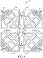
- FIG. 1 shows a MEMS sensor 100 having four proof masses 102.
- the MEMS sensor 100 having four proof masses is insensitive to linear and rotational vibration of the substrate at the drive frequency.
- the MEMS sensor 100 may be a Coriolis vibratory gyroscope.
- the four proof masses 102 may be substantially identical and arranged symmetrically around the center of the MEMS sensor 100.
- the four proof masses 102 are coupled to adjacent proof masses through proof mass flexures 104.
- each of the four proof masses 102 is coupled to a supportive substrate through substrate flexures 106.
- the proof mass flexures 104 may also be coupled to the supportive substrate.
- the masses and flexures may be fabricated from a single silicon layer.
- the single silicon layer may be of uniform thickness.
- each proof mass 102 may have mirror symmetry about a line passing through the center of the proof mass 102 and the center of the MEMS sensor 100.
- the proof masses 102 may be driven to oscillate radially at the drive mode resonant frequency.
- the symmetries of each of the proof masses 102, and the flexures 104 and 106, may ensure that the drive mode motion of each proof mass 102 is linear along a line from the center of mass towards the center of the MEMS sensor 100.
- each of the four proof masses 102 serve as both a driven mass and a sensing mass.
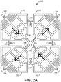
- FIG. 2A illustrates the drive mode motion of each proof mass 202 for a MEMS sensor 200.
- the proof masses 202 may oscillate such that adjacent proof masses 202 move along radial lines out of phase with one another.
- proof mass flexures 204 and substrate flexures 206 are substantially similar to proof mass flexures 104 and substrate flexures 106 in FIG. 1 .
- adjacent proof masses 202 move away from the center of the MEMS sensor 200.
- oppositely positioned proof masses 202 move towards and away from the center of MEMS sensor 200 at substantially the same time.
- the drive mode motion in FIG. 2A has zero total linear momentum and zero total angular momentum.
- FIG. 3 represents an alternative embodiment of a MEMS sensor 300 illustrating the drive mode motion of each proof mass 302 for the MEMS sensor 300, where the proof masses 302 may oscillate such that the adjacent proof masses 302 move along radial lines out of phase with one another.
- FIG. 2B is a diagram of a MEMS sensor 200 that is experiencing rotational motion while being driven according to FIG. 2A .
- proof mass flexures 204 and substrate flexures 206 are substantially similar to proof mass flexures 104 and substrate flexures 106 in FIG. 1 .
- a Coriolis force is produced on each proof mass 202.
- the Coriolis force may excite sense mode motion as shown by the arrows that are perpendicular to the lines that extend through the center of the proof mass towards the center of the MEMS sensor 200.
- the sense mode motion is sensed by sense combs that are located within each of the four proof masses 202.
- the sense combs may be oriented such that the gap between adjacent comb fingers does not vary during drive motion.
- the non-varying gap between the adjacent comb fingers may be insured by the linear motion of the drive mode.
- the sense mode motion in FIG. 2B has zero total linear momentum and zero total angular momentum. Therefore, there is zero total force and zero total moment exerted on the substrate. As a result, linear or rotational substrate vibration does not produce sense mode motion. Accordingly, the sensor output is insensitive to linear and rotational substrate vibration.
- the resonant frequency of the sense mode is not equal to the resonant frequency of the drive mode.
- the difference between the drive and sense resonant frequencies may be 100-1000 Hz and the drive resonant frequency may be 10-20 kHz, though the respective frequencies may be higher or lower.
- the non-zero separation between the resonant frequencies may provide several advantages. For example, the non-zero separation allows a wide sensor bandwidth, no need for closed loop control of the rate output of the gyroscope, and reduced sensitivity to variations in mode frequencies caused by fabrication variations, which may result in a high fabrication yield.
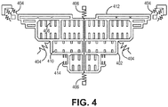
- FIG 4 illustrates a single proof mass 402 that is used as part of a four mass MEMS sensor.
- the proof mass 402 may be coupled to other proof masses in the MEMS sensor through proof mass flexures 404 and coupled to the substrate through substrate flexures 406.
- the proof mass 402 may include drive combs 412, sense combs 408 and quadrature force rebalance combs 410, and drive pickoff combs 414.
- the drive combs 412 are similar to the drive combs discussed in United States Patent 7,036,373 , which is titled "MEMS GYROSCOPE WITH HORIZONTALLY ORIENTED DRIVE ELECTRODES", patented May 2, 2006, which is incorporated herein by reference.
- the various combs interact with electrodes to acquire measurements about the movement of the proof mass 402 and to drive the movement of the proof mass 402.
- the drive electrodes may be deposited onto the substrate while other electrodes may be silicon combs attached to the substrate but residing above the substrate.
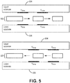
- gyroscope masses 502 may be sandwiched between an upper substrate 504 and a lower substrate 506, where the substrates are typically glass with patterned metal and dielectric layers.
- the masses 502 may be driven by horizontal drive combs using electrodes on the upper substrate 504 and lower substrate 506, such that there is no drive force in the direction of the sense motion (the direction of sense motion is out of the plane of the paper in FIG. 5 ).
- Drive electrodes can be arranged relative to a mass to provide either radially outward or radially inward electrostatic force on the mass, as shown in FIG. 5 .
- all four masses 502 may be driven with the same phase of sinusoidal drive voltage.
- the sinusoidal drive voltages are at half the drive resonant frequency, providing electrostatic forces at the drive resonant frequency. Because the electrostatic force on the proof masses is proportional to the square of the drive voltage, sinusoidal drive voltages having phases of 0° and 180° provide equivalent electrostatic force. The use of drive voltages with phases of 0° and 180° may provide cancellation of electrical currents injected into the masses by the drive voltages.
- four phases of drive voltage (0°, 90°, 180°, and 270°) at half the drive resonant frequency could be used, with all four masses having identical arrangements of drive electrodes relative to the masses.
- the drive-frequency forces provided by the 0° and 180° voltages would be out-of-phase with the drive-frequency forces provided by the 90° and 270° voltages.
- the 0° and 180° voltages may be applied to electrodes for two of the masses that move radially inward simultaneously, while the 90° and 270° voltages may be applied to electrodes for the other two masses.
- Using four phases of drive voltage allows similar drive electrodes for all four masses, for improved symmetry.
- FIG. 6 is a flow diagram of a method 600 for operating a MEMS sensor.
- Method 600 proceeds at 602, where four proof masses are driven. For example, each proof mass is driven by a plurality of drive combs, such that the four proof masses oscillate at a drive frequency along radial lines extending from the center of the MEMS sensor through the center of the respective proof mass. Further, method 600 proceeds at 604, where vibration of the four proof masses is sensed in a sense mode. In certain implementations, the resonant frequency of the sense mode may be different from the drive frequency.
Landscapes
- Physics & Mathematics (AREA)
- Engineering & Computer Science (AREA)
- General Physics & Mathematics (AREA)
- Radar, Positioning & Navigation (AREA)
- Remote Sensing (AREA)
- Gyroscopes (AREA)
Abstract
Description
- This invention was made with Government support under Government Contract Number
HR0011-16-9-0001 - This application claims the benefit of United States Provisional Patent Application Serial No.
62/342,136, filed on May 26, 2016 - Certain navigational applications have a need for high precision sensors. For example, MEMS vibratory sensors may be capable of providing high precision measurements. MEMS vibratory sensors may consist of one or more proof masses connected to a substrate through flexible suspensions (flexures) such that the MEMS sensor has two resonant modes. A velocity induced by driving the proof masses along the first resonant mode (drive mode) produces a Coriolis force on the second mode (sense mode) when the substrate is rotated. The resulting displacement of the sense mode at the drive frequency provides an output of the sensor, which is a measure of the rotation rate. Alternatively, the output of a force rebalance control loop that nulls the sense mode displacement may also provide a measure of the rotation rate.
- A common sensor output error is bias or zero-rate offset. A bias error occurs when the sensor output is non-zero when there is no substrate rotation. Systems may be able to compensate for the bias error if the bias is repeatable due to environmental conditions, such as temperature, that vary in a repeatable manner. However, there may be some level of error that is non-compensatable such as bias due to hysteresis or stress relaxation in materials, non-zero thermal time constants, aging of electronics components, or other factors.
- One cause of non-compensatable bias error is due to mechanical coupling of the sensor to a substrate. Imperfect fabrication of the sensor, which may include imperfect coupling of the sensor and substrate, may cause the driven motion of the drive mode to be asymmetric, producing a net force and/or moment on the substrate. The imbalanced force or moment exerted on the substrate can produce motion in structures external to the sensor. This external motion can in turn exert a force and/or moment on the sense mode of the sensor, producing a bias signal at the sensor output. If the external motion and/or the mechanical coupling of the substrate to the sensor has non-repeatable variation over changes in temperature, then the compensated bias of the sensor may not account for the non-repeatable variation.
- Typical two-mass MEMS sensors, known to one having skill in the art, have substantial non-compensatable bias because the sense mode motion has net angular momentum. Thus, sense mode motion can be produced by rotational vibration of the substrate even if the gyroscope is perfectly fabricated.
- Systems and methods for a four-mass vibrating mems structure are provided. In certain implementations, a MEMS sensor includes four proof masses, wherein each proof mass is driven such that the proof masses oscillate along radial lines extending from the center of the MEMS sensor through the center of the respective proof mass, each proof mass comprising a plurality of drive combs; and a plurality of sense combs. In further embodiments, the MEMS sensor includes at least one substrate having one or more drive electrodes for driving the four proof masses along the radial lines at a drive frequency, wherein a resonant frequency of a sense mode is different from the drive frequency.
- Understanding that the drawings depict only exemplary embodiments and are not therefore to be considered limiting in scope, the exemplary embodiments will be described with additional specificity and detail through the use of the accompanying drawings, in which:
-
FIG. 1 is a diagram of a MEMS sensor having four proof masses in accordance with embodiments described herein; -
FIG. 2A is a diagram of a MEMS sensor having four proof masses where the proof masses are driven along radial lines in accordance with embodiments described herein; -
FIG. 2B is a diagram of a MEMS sensor having four proof masses where the MEMS sensor experiences rotation in accordance with embodiments described herein; -
FIG. 3 is a diagram of a MEMS sensor having four proof masses where the proof masses are driven along radial lines in accordance with embodiments described herein; -
FIG. 4 is a diagram of a proof mass in accordance with embodiments described herein; -
FIG. 5 is a cross section diagram of substrates driving motion of proof masses in accordance with embodiments described herein; and -
FIG. 6 is a flow diagram of a method for driving motion of four proof masses in accordance with embodiments described herein. - In accordance with common practice, the various described features are not drawn to scale but are drawn to emphasize specific features relevant to the exemplary embodiments.
- In the following detailed description, reference is made to the accompanying drawings that form a part hereof, and in which is shown by way of illustration specific illustrative embodiments. However, it is to be understood that other embodiments may be utilized and that logical, mechanical, and electrical changes may be made. Furthermore, the method presented in the drawing figures and the specification is not to be construed as limiting the order in which the individual steps may be performed. The following detailed description is, therefore, not to be taken in a limiting sense.
- Systems and methods described herein illustrate a MEMS sensor that has reduced sensitivity to linear and rotational vibrations of the substrate at the drive frequency of the MEMS sensor. As described herein, a MEMS sensor may include four proof masses that are arranged symmetrically around the center of the MEMS sensing mechanism. For example, the four proof masses may be fabricated within a silicon layer, where the four masses are coupled to one another by a series of flexures. Each of the proof masses may have mirror symmetry about a line passing through its center of mass and the center of the sensor mechanism. The masses are driven to oscillate radially at the drive mode resonant frequency. The symmetries of each mass, flexures, and each of its adjacent masses may insure that the drive mode motion of each mass is linear along a line from its center of mass to the center of the sensor mechanism.
- Rotation of the substrate about an axis that extends out of the plane formed by the proof masses in the MEMS sensor at a slowly varying or slowly oscillating rate produces a Coriolis force on each mass. The Coriolis force excites sense mode motion of the proof masses that is perpendicular to the drive mode motion. The sense mode motion is sensed by sense combs within each of the four masses. The sense combs may be oriented such that the gap between adjacent comb fingers does not vary during drive motion, up to large drive mode displacements, e.g. 10 - 40 µm. The constant gap may be insured by the linear motion of the drive mode, which is a result of the symmetry of the masses and flexures. Large drive mode displacement may aid in providing high sensitivity of the gyroscope to an input angular rate. A constant gap between adjacent comb fingers during drive motion allows the gap to be small, which aids in providing high pickoff sensitivity of sense mode motion. The sense mode may also be linear, and the sense mode displacement is typically less than that of the drive mode.
-
FIG. 1 shows aMEMS sensor 100 having fourproof masses 102. TheMEMS sensor 100 having four proof masses is insensitive to linear and rotational vibration of the substrate at the drive frequency. In at least one implementation, theMEMS sensor 100 may be a Coriolis vibratory gyroscope. As illustrated, the fourproof masses 102 may be substantially identical and arranged symmetrically around the center of theMEMS sensor 100. The fourproof masses 102 are coupled to adjacent proof masses throughproof mass flexures 104. Also, each of the fourproof masses 102 is coupled to a supportive substrate throughsubstrate flexures 106. Further, theproof mass flexures 104 may also be coupled to the supportive substrate. In certain implementations, the masses and flexures may be fabricated from a single silicon layer. In further implementations, the single silicon layer may be of uniform thickness. - In at least one implementation, each
proof mass 102 may have mirror symmetry about a line passing through the center of theproof mass 102 and the center of theMEMS sensor 100. Theproof masses 102 may be driven to oscillate radially at the drive mode resonant frequency. The symmetries of each of theproof masses 102, and theflexures proof mass 102 is linear along a line from the center of mass towards the center of theMEMS sensor 100. As is apparent from the above description, each of the fourproof masses 102 serve as both a driven mass and a sensing mass. -
FIG. 2A illustrates the drive mode motion of eachproof mass 202 for aMEMS sensor 200. As illustrated, theproof masses 202 may oscillate such thatadjacent proof masses 202 move along radial lines out of phase with one another. As illustrated, proofmass flexures 204 andsubstrate flexures 206 are substantially similar to proofmass flexures 104 andsubstrate flexures 106 inFIG. 1 . Further, when aproof mass 202 moves toward the center of theMEMS sensor 200,adjacent proof masses 202 move away from the center of theMEMS sensor 200. Accordingly, oppositely positionedproof masses 202 move towards and away from the center ofMEMS sensor 200 at substantially the same time. The drive mode motion inFIG. 2A has zero total linear momentum and zero total angular momentum. Therefore, there is zero total force and zero total moment exerted on the substrate, resulting in minimal induced substrate vibration.FIG. 3 represents an alternative embodiment of aMEMS sensor 300 illustrating the drive mode motion of eachproof mass 302 for theMEMS sensor 300, where theproof masses 302 may oscillate such that theadjacent proof masses 302 move along radial lines out of phase with one another. -
FIG. 2B is a diagram of aMEMS sensor 200 that is experiencing rotational motion while being driven according toFIG. 2A . As illustrated, proofmass flexures 204 andsubstrate flexures 206 are substantially similar to proofmass flexures 104 andsubstrate flexures 106 inFIG. 1 . As theMEMS sensor 200 experiences rotation of the substrate about an axis that extends perpendicular to the plane formed by the proof masses at a slowly varying or slowly oscillating rate (oscillation frequency much less than the drive frequency) a Coriolis force is produced on eachproof mass 202. The Coriolis force may excite sense mode motion as shown by the arrows that are perpendicular to the lines that extend through the center of the proof mass towards the center of theMEMS sensor 200. The sense mode motion is sensed by sense combs that are located within each of the fourproof masses 202. In certain implementations, the sense combs may be oriented such that the gap between adjacent comb fingers does not vary during drive motion. The non-varying gap between the adjacent comb fingers may be insured by the linear motion of the drive mode. The sense mode motion inFIG. 2B has zero total linear momentum and zero total angular momentum. Therefore, there is zero total force and zero total moment exerted on the substrate. As a result, linear or rotational substrate vibration does not produce sense mode motion. Accordingly, the sensor output is insensitive to linear and rotational substrate vibration. - In certain implementations, the resonant frequency of the sense mode is not equal to the resonant frequency of the drive mode. For example, the difference between the drive and sense resonant frequencies may be 100-1000 Hz and the drive resonant frequency may be 10-20 kHz, though the respective frequencies may be higher or lower. The non-zero separation between the resonant frequencies may provide several advantages. For example, the non-zero separation allows a wide sensor bandwidth, no need for closed loop control of the rate output of the gyroscope, and reduced sensitivity to variations in mode frequencies caused by fabrication variations, which may result in a high fabrication yield.
-
FIG 4 illustrates asingle proof mass 402 that is used as part of a four mass MEMS sensor. As illustrated here and above, theproof mass 402 may be coupled to other proof masses in the MEMS sensor through proofmass flexures 404 and coupled to the substrate throughsubstrate flexures 406. Theproof mass 402 may include drive combs 412, sense combs 408 and quadrature force rebalance combs 410, and drive pickoff combs 414. In certain implementations, the drive combs 412 are similar to the drive combs discussed in United States Patent7,036,373 , which is titled "MEMS GYROSCOPE WITH HORIZONTALLY ORIENTED DRIVE ELECTRODES", patented May 2, 2006, which is incorporated herein by reference. The various combs interact with electrodes to acquire measurements about the movement of theproof mass 402 and to drive the movement of theproof mass 402. In at least one implementation, the drive electrodes may be deposited onto the substrate while other electrodes may be silicon combs attached to the substrate but residing above the substrate. - As illustrated in
FIG. 5 ,gyroscope masses 502 may be sandwiched between anupper substrate 504 and alower substrate 506, where the substrates are typically glass with patterned metal and dielectric layers. Themasses 502 may be driven by horizontal drive combs using electrodes on theupper substrate 504 andlower substrate 506, such that there is no drive force in the direction of the sense motion (the direction of sense motion is out of the plane of the paper inFIG. 5 ). Drive electrodes can be arranged relative to a mass to provide either radially outward or radially inward electrostatic force on the mass, as shown inFIG. 5 . Thus, all fourmasses 502 may be driven with the same phase of sinusoidal drive voltage. Typically, the sinusoidal drive voltages are at half the drive resonant frequency, providing electrostatic forces at the drive resonant frequency. Because the electrostatic force on the proof masses is proportional to the square of the drive voltage, sinusoidal drive voltages having phases of 0° and 180° provide equivalent electrostatic force. The use of drive voltages with phases of 0° and 180° may provide cancellation of electrical currents injected into the masses by the drive voltages. - Alternatively, four phases of drive voltage (0°, 90°, 180°, and 270°) at half the drive resonant frequency could be used, with all four masses having identical arrangements of drive electrodes relative to the masses. The drive-frequency forces provided by the 0° and 180° voltages would be out-of-phase with the drive-frequency forces provided by the 90° and 270° voltages. The 0° and 180° voltages may be applied to electrodes for two of the masses that move radially inward simultaneously, while the 90° and 270° voltages may be applied to electrodes for the other two masses. Using four phases of drive voltage allows similar drive electrodes for all four masses, for improved symmetry.
-
FIG. 6 is a flow diagram of amethod 600 for operating a MEMS sensor.Method 600 proceeds at 602, where four proof masses are driven. For example, each proof mass is driven by a plurality of drive combs, such that the four proof masses oscillate at a drive frequency along radial lines extending from the center of the MEMS sensor through the center of the respective proof mass. Further,method 600 proceeds at 604, where vibration of the four proof masses is sensed in a sense mode. In certain implementations, the resonant frequency of the sense mode may be different from the drive frequency. -
- Example 1 includes a MEMS sensor, the MEMS sensor comprising: four proof masses, wherein each proof mass is driven such that the proof masses oscillate along radial lines extending from the center of the MEMS sensor through the center of the respective proof mass, each proof mass comprising: a plurality of drive combs; and a plurality of sense combs; and at least one substrate having one or more drive electrodes for driving the four proof masses along the radial lines at a drive frequency, wherein a resonant frequency of a sense mode is different from the drive frequency.
- Example 2 includes the MEMS sensor of Example 1, wherein the sense combs are oriented such that the gap between adjacent comb fingers does not vary when the proof masses oscillate along the radial lines.
- Example 3 includes the MEMS sensor of any of Examples 1-2, wherein the MEMS sensor vibrates with zero angular momentum and zero linear momentum.
- Example 4 includes the MEMS sensor of any of Examples 1-3, wherein each proof mass is coupled to adjacent proof masses through proof mass flexures, wherein each proof mass is coupled to the supportive substrate through substrate flexures.
- Example 5 includes the MEMS sensor of any of Examples 1-4, wherein each proof mass is driven out of phase with adjacent proof masses.
- Example 6 includes the MEMS sensor of any of Examples 1-5, wherein the at least one substrate comprise an upper substrate and a lower substrate, wherein the four proof masses are positioned between the upper substrate and the lower substrate.
- Example 7 includes the MEMS sensor of Example 6, wherein electrodes positioned on the upper substrate and lower substrate drive horizontal drive combs on the four proof masses.
- Example 8 includes the MEMS sensor of any of Examples 1-7, wherein the MEMS sensor is a Coriolis vibratory gyroscope.
- Example 9 includes a method for operating a MEMS sensor, the method comprising: driving four proof masses, wherein each proof mass is driven by a plurality of drive combs, such that the four proof masses oscillate at a drive frequency along radial lines extending from the center of the MEMS sensor through the center of the respective proof mass; and sensing vibration of the four proof masses in a sense mode, wherein the resonant frequency of the sense mode is different from the drive frequency.
- Example 10 includes the method of Example 9, wherein sensing vibration of the four proof masses is performed by a plurality of sense electrodes attached to at least one substrate, where the sense electrodes sense motion of sense combs formed on the four proof masses.
- Example 11 includes the method of Example 10, wherein the at least one substrate comprise an upper substrate and a lower substrate, wherein the four proof masses are positioned between the upper substrate and the lower substrate.
- Example 12 includes the method of Example 11, wherein electrodes positioned on the upper substrate and lower substrate drive the drive combs on the four proof masses.
- Example 13 includes the method of any of Examples 10-12, wherein the sense combs are oriented such that the gap between adjacent comb fingers does not vary when the proof masses oscillate along the radial lines.
- Example 14 includes the method of any of Examples 9-13, wherein the MEMS sensor vibrates with zero angular momentum and zero linear momentum.
- Example 15 includes the method of any of Examples 9-14, wherein each proof mass is coupled to adjacent proof masses through proof mass flexures, wherein each proof mass is coupled to the supportive substrate through substrate flexures.
- Example 16 includes the method of any of Examples 9-15, wherein each proof mass is driven out of phase with adjacent proof masses.
- Example 17 includes the method of any of Examples 9-16, wherein the MEMS sensor is a Coriolis vibratory gyroscope.
- Example 18 includes a MEMS sensor, the MEMS sensor comprising: four proof masses, wherein each proof mass is driven such that the proof masses oscillate along radial lines extending from the center of the MEMS sensor through the center of the respective proof mass, each proof mass comprising: a plurality of drive combs; and a plurality of sense combs; at least one substrate having one or more drive electrodes for driving the four proof masses along the radial lines at a drive frequency, wherein a resonant frequency of a sense mode is different from the drive frequency; and a plurality of flexures that couple each proof mass to adjacent proof masses and couple the four proof masses to the supportive substrate.
- Example 19 includes the MEMS sensor of Example 18, wherein the sense combs are oriented such that the gap between adjacent comb fingers does not vary when the proof masses oscillate along the radial lines.
- Example 20 includes the MEMS sensor of any of Examples 18-19, wherein the MEMS sensor vibrates with zero angular momentum and zero linear momentum. Although specific embodiments have been illustrated and described herein, it will be appreciated by those of ordinary skill in the art that any arrangement, which is calculated to achieve the same purpose, may be substituted for the specific embodiments shown. Therefore, it is manifestly intended that this invention be limited only by the claims and the equivalents thereof.
Claims (10)
- A MEMS sensor, the MEMS sensor comprising:four proof masses (102), wherein each proof mass (102) is driven such that the proof masses (102) oscillate along radial lines extending from the center of the MEMS sensor through the center of the respective proof mass (102), each proof mass (102) comprising:a plurality of drive combs; anda plurality of sense combs; andat least one substrate having one or more drive electrodes for driving the four proof masses (102) along the radial lines at a drive frequency, wherein a resonant frequency of a sense mode is different from the drive frequency.
- The MEMS sensor of claim 1, wherein the sense combs are oriented such that the gap between adjacent comb fingers does not vary when the proof masses oscillate along the radial lines.
- The MEMS sensor of claim 1, wherein the MEMS sensor vibrates with zero angular momentum and zero linear momentum.
- The MEMS sensor of claim 1, wherein each proof mass (102) is coupled to adjacent proof masses (102) through proof mass flexures (104), wherein each proof mass is coupled to the supportive substrate through substrate flexures (106).
- The MEMS sensor of claim 1, wherein each proof mass (102) is driven out of phase with adjacent proof masses (102).
- The MEMS sensor of claim 1, wherein the at least one substrate comprise an upper substrate (504) and a lower substrate (506), wherein the four proof masses (102) are positioned between the upper substrate (504) and the lower substrate (506).
- The MEMS sensor of claim 6, wherein electrodes positioned on the upper substrate and lower substrate drive horizontal drive combs on the four proof masses.
- A method for operating a MEMS sensor, the method comprising:driving four proof masses (102), wherein each proof mass (102) is driven by a plurality of drive combs, such that the four proof masses oscillate at a drive frequency along radial lines extending from the center of the MEMS sensor through the center of the respective proof mass; andsensing vibration of the four proof masses in a sense mode, wherein the resonant frequency of the sense mode is different from the drive frequency.
- The method of claim 8, wherein sensing vibration of the four proof masses (102) is performed by a plurality of sense electrodes attached to at least one substrate, where the sense electrodes sense motion of sense combs formed on the four proof masses (102).
- The method of claim 9, wherein the at least one substrate comprise an upper substrate (504) and a lower substrate (506), wherein the four proof masses (102) are positioned between the upper substrate (504) and the lower substrate (506).
Applications Claiming Priority (2)
| Application Number | Priority Date | Filing Date | Title |
|---|---|---|---|
| US201662342136P | 2016-05-26 | 2016-05-26 | |
| US15/466,784 US10371521B2 (en) | 2016-05-26 | 2017-03-22 | Systems and methods for a four-mass vibrating MEMS structure |
Publications (2)
| Publication Number | Publication Date |
|---|---|
| EP3249356A1 true EP3249356A1 (en) | 2017-11-29 |
| EP3249356B1 EP3249356B1 (en) | 2019-10-30 |
Family
ID=58413008
Family Applications (1)
| Application Number | Title | Priority Date | Filing Date |
|---|---|---|---|
| EP17162859.7A Active EP3249356B1 (en) | 2016-05-26 | 2017-03-24 | Systems and methods for a four-mass vibrating mems structure |
Country Status (2)
| Country | Link |
|---|---|
| US (1) | US10371521B2 (en) |
| EP (1) | EP3249356B1 (en) |
Cited By (2)
| Publication number | Priority date | Publication date | Assignee | Title |
|---|---|---|---|---|
| EP3572770A1 (en) | 2018-05-08 | 2019-11-27 | Murata Manufacturing Co., Ltd. | Synchronization structure for gyroscope |
| CN114113679A (en) * | 2020-07-30 | 2022-03-01 | 意法半导体股份有限公司 | Wide-bandwidth MEMS accelerometer for vibration detection |
Families Citing this family (10)
| Publication number | Priority date | Publication date | Assignee | Title |
|---|---|---|---|---|
| US10696541B2 (en) | 2016-05-26 | 2020-06-30 | Honeywell International Inc. | Systems and methods for bias suppression in a non-degenerate MEMS sensor |
| US10794702B2 (en) * | 2017-12-13 | 2020-10-06 | Invensense, Inc. | On-chip gap measurement |
| EP3671118B1 (en) * | 2018-12-19 | 2021-08-25 | Murata Manufacturing Co., Ltd. | Vibration-robust multiaxis gyroscope |
| EP3696503B1 (en) * | 2019-02-15 | 2022-10-26 | Murata Manufacturing Co., Ltd. | Vibration-robust multiaxis gyroscope |
| JP6879391B2 (en) * | 2019-02-15 | 2021-06-02 | 株式会社村田製作所 | Multi-axis gyroscope with sync frame |
| JP6897806B2 (en) * | 2019-02-15 | 2021-07-07 | 株式会社村田製作所 | Balanced multi-axis gyroscope |
| US12012327B2 (en) | 2020-03-12 | 2024-06-18 | Honeywell International Inc. | Methods for vibration immunity to suppress bias errors in sensor devices |
| US12270652B2 (en) * | 2021-11-22 | 2025-04-08 | Invensense, Inc. | 4-points phase and sensitivity estimation algorithm and related architecture |
| CN114719833B (en) * | 2022-02-22 | 2025-04-22 | 瑞声开泰科技(武汉)有限公司 | A MEMS gyroscope |
| CN115876176A (en) * | 2022-10-28 | 2023-03-31 | 瑞声开泰科技(武汉)有限公司 | Multi-mass MEMS gyroscope in orthogonal arrangement |
Citations (7)
| Publication number | Priority date | Publication date | Assignee | Title |
|---|---|---|---|---|
| US7036373B2 (en) | 2004-06-29 | 2006-05-02 | Honeywell International, Inc. | MEMS gyroscope with horizontally oriented drive electrodes |
| US7100446B1 (en) * | 2004-07-20 | 2006-09-05 | The Regents Of The University Of California | Distributed-mass micromachined gyroscopes operated with drive-mode bandwidth enhancement |
| US20100223996A1 (en) * | 2006-06-16 | 2010-09-09 | Sony Corporation | Inertial sensor |
| US20120017677A1 (en) * | 2008-11-11 | 2012-01-26 | Peter Merz | Micromechanical coriolis rate of rotation sensor |
| US20120048017A1 (en) * | 2009-02-27 | 2012-03-01 | Sensordynamics Ag | Microgyroscope for Determining Rotational Movements About an X and/or Y and Z Axis |
| US20140047921A1 (en) * | 2009-09-11 | 2014-02-20 | Invensense, Inc. | Extension-mode angular velocity sensor |
| US20160025492A1 (en) * | 2009-02-27 | 2016-01-28 | Maxim Integrated Products, Inc. | MEMS Gyroscope for Determining Rotational Movements about an X, Y, and/or Z Axis |
Family Cites Families (75)
| Publication number | Priority date | Publication date | Assignee | Title |
|---|---|---|---|---|
| US5349855A (en) | 1992-04-07 | 1994-09-27 | The Charles Stark Draper Laboratory, Inc. | Comb drive micromechanical tuning fork gyro |
| JPH09196682A (en) | 1996-01-19 | 1997-07-31 | Matsushita Electric Ind Co Ltd | Angular velocity sensor and acceleration sensor |
| US6151965A (en) | 1998-01-21 | 2000-11-28 | Denso Corporation | Structure of angular rate sensor for minimizing output noise |
| JP3796991B2 (en) | 1998-12-10 | 2006-07-12 | 株式会社デンソー | Angular velocity sensor |
| JP2005503857A (en) | 2001-09-25 | 2005-02-10 | ヌバシブ, インコーポレイテッド | Systems and methods for performing surgical procedures and surgical diagnosis |
| US6651500B2 (en) | 2001-10-03 | 2003-11-25 | Litton Systems, Inc. | Micromachined silicon tuned counterbalanced accelerometer-gyro with quadrature nulling |
| JP3870895B2 (en) | 2002-01-10 | 2007-01-24 | 株式会社村田製作所 | Angular velocity sensor |
| DE03707756T1 (en) | 2002-02-06 | 2005-05-04 | Analog Devices Inc | MICRO-MADE CIRCLES |
| RU2222780C1 (en) | 2002-07-10 | 2004-01-27 | Открытое акционерное общество Арзамасское научно-производственное предприятие "Темп-Авиа" | Sensitive element of micromechanical gyroscope |
| US7040163B2 (en) | 2002-08-12 | 2006-05-09 | The Boeing Company | Isolated planar gyroscope with internal radial sensing and actuation |
| KR20050107470A (en) | 2003-02-28 | 2005-11-11 | 배 시스템즈 피엘시 | An accelerometer |
| RU2234679C2 (en) | 2003-03-21 | 2004-08-20 | Открытое акционерное общество Арзамасское научно-производственное предприятие "Темп-Авиа" | Angular velocity micromechanical sensor |
| US6837107B2 (en) | 2003-04-28 | 2005-01-04 | Analog Devices, Inc. | Micro-machined multi-sensor providing 1-axis of acceleration sensing and 2-axes of angular rate sensing |
| US6848304B2 (en) | 2003-04-28 | 2005-02-01 | Analog Devices, Inc. | Six degree-of-freedom micro-machined multi-sensor |
| DE10360963B4 (en) | 2003-12-23 | 2007-05-16 | Litef Gmbh | Method for measuring rotation rates / accelerations using a yaw rate Coriolis gyro and suitable Coriolis gyro |
| DE10360962B4 (en) | 2003-12-23 | 2007-05-31 | Litef Gmbh | Method for quadrature bias compensation in a Coriolis gyro and suitable Coriolis gyro |
| RU2251077C1 (en) | 2004-01-05 | 2005-04-27 | Государственное образовательное учреждение высшего профессионального образования "Таганрогский государственный радиотехнический университет" (ТРТУ) | Integrating micromechanical gyro |
| DE602004031938D1 (en) | 2004-08-13 | 2011-05-05 | St Microelectronics Srl | Microelectromechanical structure, in particular acceleration sensor, with improved insensitivity to thermal and mechanical stresses |
| EP1645847B1 (en) | 2004-10-08 | 2014-07-02 | STMicroelectronics Srl | Temperature compensated micro-electromechanical device and method of temperature compensation in a micro-electromechanical device |
| FR2888318B1 (en) | 2005-07-05 | 2007-09-14 | Thales Sa | MICRO-FACTORY GYROMETRIC SENSOR PROVIDING A DIFFERENTIAL MEASUREMENT OF VIBRATING MASS MOVEMENT |
| US7562573B2 (en) | 2005-07-21 | 2009-07-21 | Evigia Systems, Inc. | Integrated sensor and circuitry and process therefor |
| JP4702942B2 (en) | 2005-10-14 | 2011-06-15 | Necトーキン株式会社 | Vibrating gyro element and vibrating gyro |
| US8113050B2 (en) | 2006-01-25 | 2012-02-14 | The Regents Of The University Of California | Robust six degree-of-freedom micromachined gyroscope with anti-phase drive scheme and method of operation of the same |
| JP5030135B2 (en) | 2006-07-18 | 2012-09-19 | Necトーキン株式会社 | Piezoelectric single crystal vibrator and piezoelectric vibration gyro |
| JP2008145325A (en) | 2006-12-12 | 2008-06-26 | Nec Tokin Corp | Vibration gyro |
| JP4343965B2 (en) | 2007-02-15 | 2009-10-14 | Okiセミコンダクタ株式会社 | Inertial sensor |
| US8006557B2 (en) | 2007-05-16 | 2011-08-30 | Intellisense Software Corporation | Multi-axis sensor |
| DE102007030119A1 (en) | 2007-06-29 | 2009-01-02 | Litef Gmbh | Coriolis |
| DE102007030120B4 (en) | 2007-06-29 | 2010-04-08 | Litef Gmbh | Yaw rate sensor |
| US8061201B2 (en) | 2007-07-13 | 2011-11-22 | Georgia Tech Research Corporation | Readout method and electronic bandwidth control for a silicon in-plane tuning fork gyroscope |
| WO2009107573A1 (en) | 2008-02-25 | 2009-09-03 | アルプス電気株式会社 | Angular velocity sensor |
| CN101261126B (en) | 2008-04-10 | 2010-06-02 | 上海交通大学 | Micro Solid Mode Gyroscope |
| DE102008002748A1 (en) | 2008-06-27 | 2009-12-31 | Sensordynamics Ag | Microgyroscope |
| CN101363731B (en) | 2008-09-25 | 2011-01-26 | 中国人民解放军国防科学技术大学 | Quartz micromechanical gyroscope based on shear stress detection and its manufacturing method |
| EP2177875A3 (en) | 2008-10-14 | 2013-04-24 | Watson Industries, Inc. | A Vibrating Structural Gyroscope with Quadrature Control |
| JP2010096695A (en) | 2008-10-20 | 2010-04-30 | Nec Tokin Corp | Vibration gyroscope |
| US20100095768A1 (en) | 2008-10-20 | 2010-04-22 | Custom Sensors & Technologies, Inc. | Micromachined torsional gyroscope with anti-phase linear sense transduction |
| IT1391973B1 (en) | 2008-11-26 | 2012-02-02 | St Microelectronics Rousset | MONO OR BIASSIAL MICROELECTROMECHANICAL GYROSCOPE WITH INCREASED SENSITIVITY TO THE ANGULAR SPEED DETECTION |
| IT1391972B1 (en) | 2008-11-26 | 2012-02-02 | St Microelectronics Rousset | MICROELETTROMECHANICAL GYROSCOPE WITH ROTARY DRIVE MOVEMENT AND IMPROVED ELECTRICAL CHARACTERISTICS |
| US8256290B2 (en) * | 2009-03-17 | 2012-09-04 | Minyao Mao | Tri-axis angular rate sensor |
| DE102009001922A1 (en) * | 2009-03-26 | 2010-09-30 | Sensordynamics Ag | Micro-gyroscope for determining rotational movements about three mutually perpendicular spatial axes x, y and z |
| IT1394007B1 (en) | 2009-05-11 | 2012-05-17 | St Microelectronics Rousset | MICROELETTROMECANICAL STRUCTURE WITH IMPROVED REJECTION OF ACCELERATION DISORDERS |
| FR2945621B1 (en) | 2009-05-15 | 2011-08-26 | Commissariat Energie Atomique | COUPLING STRUCTURE FOR RESIN GYROMETER |
| US8640541B2 (en) | 2009-05-27 | 2014-02-04 | King Abdullah University Of Science And Technology | MEMS mass-spring-damper systems using an out-of-plane suspension scheme |
| US8322213B2 (en) | 2009-06-12 | 2012-12-04 | The Regents Of The University Of California | Micromachined tuning fork gyroscopes with ultra-high sensitivity and shock rejection |
| CN102483328B (en) | 2009-09-09 | 2015-08-05 | 大陆-特韦斯贸易合伙股份公司及两合公司 | There is linear and rotation earthquake element twin shaft, antidetonation rotation rate sensor |
| RU2423668C1 (en) | 2009-12-01 | 2011-07-10 | Государственное образовательное учреждение высшего профессионального образования Московский государственный институт электронной техники (технический университет) (МИЭТ) | Detecting element of micromechanical gyroscope |
| ITTO20091042A1 (en) * | 2009-12-24 | 2011-06-25 | St Microelectronics Srl | MICROELETTROMECHANICAL INTEGRATED GYROSCOPE WITH IMPROVED DRIVE STRUCTURE |
| DE102010028005A1 (en) | 2010-04-20 | 2011-10-20 | Sensordynamics Ag | Micro gyroscope for detecting movements |
| US8584522B2 (en) | 2010-04-30 | 2013-11-19 | Qualcomm Mems Technologies, Inc. | Micromachined piezoelectric x-axis gyroscope |
| US8317104B2 (en) * | 2010-08-05 | 2012-11-27 | Hand Held Products, Inc. | Image engine with integrated circuit structure for indicia reading terminal |
| CN201945318U (en) | 2011-02-14 | 2011-08-24 | 孙博华 | Heartbeat type single structure three-axis micro-electromechanical gyroscope |
| JP5822177B2 (en) | 2011-05-20 | 2015-11-24 | セイコーエプソン株式会社 | Gyro sensor, electronic equipment |
| CN102305626B (en) | 2011-07-07 | 2013-04-17 | 西北工业大学 | Novel MEMS (micro electro mechanical system) centrifugal-type gyroscope |
| CN102278982B (en) | 2011-07-13 | 2013-07-24 | 中国人民解放军国防科学技术大学 | Restraining method for coupling error of micro silicon gyroscope with four mass blocks |
| ITTO20110806A1 (en) | 2011-09-12 | 2013-03-13 | St Microelectronics Srl | MICROELETTROMECANICAL DEVICE INTEGRATING A GYROSCOPE AND AN ACCELEROMETER |
| US8991247B2 (en) | 2011-10-21 | 2015-03-31 | The Regents Of The University Of California | High range digital angular rate sensor based on frequency modulation |
| FR2983574B1 (en) | 2011-12-06 | 2014-01-10 | Sagem Defense Securite | BALANCED MEMS TYPE INERTIAL ANGULAR SENSOR AND METHOD FOR BALANCING SENSOR THEREOF |
| EP2607849A1 (en) | 2011-12-22 | 2013-06-26 | Tronics Microsystems S.A. | Multiaxial micro-electronic inertial sensor |
| DE102011057081A1 (en) * | 2011-12-28 | 2013-07-04 | Maxim Integrated Products, Inc. | Micro rotation rate sensor and method for operating a micro yaw rate sensor |
| WO2013108804A1 (en) | 2012-01-19 | 2013-07-25 | 株式会社村田製作所 | Vibrating gyroscope |
| CN103213939B (en) | 2012-01-19 | 2016-01-20 | 北京自动化控制设备研究所 | A kind of processing method of four mass silicon microelectromechanicgyroscope gyroscope structures |
| US9759563B2 (en) | 2012-01-31 | 2017-09-12 | Nxp Usa, Inc. | Vibration robust x-axis ring gyro transducer |
| CN103245340B (en) | 2012-02-01 | 2016-07-13 | 苏州敏芯微电子技术股份有限公司 | A kind of single-chip tri-axial gyroscope |
| CN102636162B (en) | 2012-03-26 | 2015-02-11 | 北京航天时代光电科技有限公司 | Three-axis micro-mechanical gyroscope |
| US9212908B2 (en) | 2012-04-26 | 2015-12-15 | Analog Devices, Inc. | MEMS gyroscopes with reduced errors |
| CN103575263B (en) | 2012-07-19 | 2017-03-29 | 水木智芯科技(北京)有限公司 | Four mass full decoupling condenser type single shaft micro-mechanical gyroscopes |
| CN202793402U (en) | 2012-07-19 | 2013-03-13 | 水木智芯科技(北京)有限公司 | Full-decoupling capacitive uniaxial micromechanical gyroscope with four mass blocks |
| US20140035243A1 (en) * | 2012-07-31 | 2014-02-06 | James Bruce Hoop | Apparatus for coupling a stir stick to an electric drill |
| US9006642B2 (en) | 2012-08-21 | 2015-04-14 | Delta Electronics, Inc. | Focus adjustable apparatus |
| US9194704B2 (en) * | 2013-03-13 | 2015-11-24 | Freescale Semiconductor, Inc. | Angular rate sensor having multiple axis sensing capability |
| FI126071B (en) * | 2014-01-28 | 2016-06-15 | Murata Manufacturing Co | Improved gyroscope structure and gyroscope |
| FR3022996B1 (en) | 2014-06-27 | 2017-12-01 | Thales Sa | ANGULAR INERTIAL MEMS SENSOR OPERATING IN DIAPASON MODE |
| US10247554B2 (en) | 2014-09-24 | 2019-04-02 | The Regents Of The University Of California | Fully balanced micro-machined inertial sensor |
| ITUB20159197A1 (en) | 2015-12-29 | 2017-06-29 | St Microelectronics Srl | MICROELETTROMECHANICAL GYROSCOPE WITH DISORDER REJECTION AND METHOD OF DETECTING AN ANGULAR SPEED |
-
2017
- 2017-03-22 US US15/466,784 patent/US10371521B2/en active Active
- 2017-03-24 EP EP17162859.7A patent/EP3249356B1/en active Active
Patent Citations (7)
| Publication number | Priority date | Publication date | Assignee | Title |
|---|---|---|---|---|
| US7036373B2 (en) | 2004-06-29 | 2006-05-02 | Honeywell International, Inc. | MEMS gyroscope with horizontally oriented drive electrodes |
| US7100446B1 (en) * | 2004-07-20 | 2006-09-05 | The Regents Of The University Of California | Distributed-mass micromachined gyroscopes operated with drive-mode bandwidth enhancement |
| US20100223996A1 (en) * | 2006-06-16 | 2010-09-09 | Sony Corporation | Inertial sensor |
| US20120017677A1 (en) * | 2008-11-11 | 2012-01-26 | Peter Merz | Micromechanical coriolis rate of rotation sensor |
| US20120048017A1 (en) * | 2009-02-27 | 2012-03-01 | Sensordynamics Ag | Microgyroscope for Determining Rotational Movements About an X and/or Y and Z Axis |
| US20160025492A1 (en) * | 2009-02-27 | 2016-01-28 | Maxim Integrated Products, Inc. | MEMS Gyroscope for Determining Rotational Movements about an X, Y, and/or Z Axis |
| US20140047921A1 (en) * | 2009-09-11 | 2014-02-20 | Invensense, Inc. | Extension-mode angular velocity sensor |
Cited By (3)
| Publication number | Priority date | Publication date | Assignee | Title |
|---|---|---|---|---|
| EP3572770A1 (en) | 2018-05-08 | 2019-11-27 | Murata Manufacturing Co., Ltd. | Synchronization structure for gyroscope |
| US11085768B2 (en) | 2018-05-08 | 2021-08-10 | Murata Manufacturing Co., Ltd. | Synchronization structure for gyroscope |
| CN114113679A (en) * | 2020-07-30 | 2022-03-01 | 意法半导体股份有限公司 | Wide-bandwidth MEMS accelerometer for vibration detection |
Also Published As
| Publication number | Publication date |
|---|---|
| US10371521B2 (en) | 2019-08-06 |
| EP3249356B1 (en) | 2019-10-30 |
| US20180231384A1 (en) | 2018-08-16 |
Similar Documents
| Publication | Publication Date | Title |
|---|---|---|
| US10371521B2 (en) | Systems and methods for a four-mass vibrating MEMS structure | |
| KR101166866B1 (en) | Mems gyroscope with horizontally oriented drive electrodes | |
| KR101178692B1 (en) | Coriolis Gyroscope | |
| US8555718B2 (en) | Piezoelectric transducers | |
| US11913808B2 (en) | Inertial sensor and method of inertial sensing with tuneable mode coupling strength | |
| US10746548B2 (en) | Ring gyroscope structural features | |
| JP2010515021A (en) | Vibrating gyro with parasitic mode damping | |
| JP2006053152A (en) | Microgyrometer employing frequency detection | |
| KR19980086521A (en) | Monocrystalline Vibration Beam Angular Velocity Sensor | |
| EP3249355B1 (en) | Systems and methods for bias suppression in a non-degenerate mems sensor | |
| US7040162B2 (en) | Vibrating mass gyro | |
| JPH11337345A (en) | Vibratory microgyrometer | |
| EP3312558B1 (en) | Hemispherical resonator gyroscope | |
| JP2008134243A (en) | Dual mode MEMS sensor | |
| US11441902B2 (en) | Method of optimising the performance of a MEMS rate gyroscope | |
| KR100493149B1 (en) | Symmetrical Z-axis gyroscope and fabricating method thereof | |
| EP3791133B1 (en) | Piezoelectric ring gyroscope | |
| KR100319920B1 (en) | Laterally driving gimbal type gyroscope having unbalanced inner torsional gimbal | |
| KR101433590B1 (en) | Parameter Amplification of MEMS Gyroscope by Capacitance Modulation | |
| Maeda et al. | Out-of-plane axis SOI MEMS gyroscope with initially displaced vertical sensing comb | |
| Ozer et al. | Ferroelectric based microgyroscope for inertial measurement unit: Modeling and simulation |
Legal Events
| Date | Code | Title | Description |
|---|---|---|---|
| PUAI | Public reference made under article 153(3) epc to a published international application that has entered the european phase |
Free format text: ORIGINAL CODE: 0009012 |
|
| STAA | Information on the status of an ep patent application or granted ep patent |
Free format text: STATUS: REQUEST FOR EXAMINATION WAS MADE |
|
| 17P | Request for examination filed |
Effective date: 20170324 |
|
| AK | Designated contracting states |
Kind code of ref document: A1 Designated state(s): AL AT BE BG CH CY CZ DE DK EE ES FI FR GB GR HR HU IE IS IT LI LT LU LV MC MK MT NL NO PL PT RO RS SE SI SK SM TR |
|
| AX | Request for extension of the european patent |
Extension state: BA ME |
|
| STAA | Information on the status of an ep patent application or granted ep patent |
Free format text: STATUS: EXAMINATION IS IN PROGRESS |
|
| 17Q | First examination report despatched |
Effective date: 20180817 |
|
| GRAP | Despatch of communication of intention to grant a patent |
Free format text: ORIGINAL CODE: EPIDOSNIGR1 |
|
| STAA | Information on the status of an ep patent application or granted ep patent |
Free format text: STATUS: GRANT OF PATENT IS INTENDED |
|
| INTG | Intention to grant announced |
Effective date: 20190618 |
|
| GRAS | Grant fee paid |
Free format text: ORIGINAL CODE: EPIDOSNIGR3 |
|
| GRAA | (expected) grant |
Free format text: ORIGINAL CODE: 0009210 |
|
| STAA | Information on the status of an ep patent application or granted ep patent |
Free format text: STATUS: THE PATENT HAS BEEN GRANTED |
|
| AK | Designated contracting states |
Kind code of ref document: B1 Designated state(s): AL AT BE BG CH CY CZ DE DK EE ES FI FR GB GR HR HU IE IS IT LI LT LU LV MC MK MT NL NO PL PT RO RS SE SI SK SM TR |
|
| REG | Reference to a national code |
Ref country code: GB Ref legal event code: FG4D |
|
| REG | Reference to a national code |
Ref country code: CH Ref legal event code: EP |
|
| REG | Reference to a national code |
Ref country code: AT Ref legal event code: REF Ref document number: 1196634 Country of ref document: AT Kind code of ref document: T Effective date: 20191115 |
|
| REG | Reference to a national code |
Ref country code: DE Ref legal event code: R096 Ref document number: 602017008141 Country of ref document: DE |
|
| REG | Reference to a national code |
Ref country code: IE Ref legal event code: FG4D |
|
| REG | Reference to a national code |
Ref country code: LT Ref legal event code: MG4D |
|
| PG25 | Lapsed in a contracting state [announced via postgrant information from national office to epo] |
Ref country code: GR Free format text: LAPSE BECAUSE OF FAILURE TO SUBMIT A TRANSLATION OF THE DESCRIPTION OR TO PAY THE FEE WITHIN THE PRESCRIBED TIME-LIMIT Effective date: 20200131 Ref country code: PL Free format text: LAPSE BECAUSE OF FAILURE TO SUBMIT A TRANSLATION OF THE DESCRIPTION OR TO PAY THE FEE WITHIN THE PRESCRIBED TIME-LIMIT Effective date: 20191030 Ref country code: NO Free format text: LAPSE BECAUSE OF FAILURE TO SUBMIT A TRANSLATION OF THE DESCRIPTION OR TO PAY THE FEE WITHIN THE PRESCRIBED TIME-LIMIT Effective date: 20200130 Ref country code: LV Free format text: LAPSE BECAUSE OF FAILURE TO SUBMIT A TRANSLATION OF THE DESCRIPTION OR TO PAY THE FEE WITHIN THE PRESCRIBED TIME-LIMIT Effective date: 20191030 Ref country code: SE Free format text: LAPSE BECAUSE OF FAILURE TO SUBMIT A TRANSLATION OF THE DESCRIPTION OR TO PAY THE FEE WITHIN THE PRESCRIBED TIME-LIMIT Effective date: 20191030 Ref country code: BG Free format text: LAPSE BECAUSE OF FAILURE TO SUBMIT A TRANSLATION OF THE DESCRIPTION OR TO PAY THE FEE WITHIN THE PRESCRIBED TIME-LIMIT Effective date: 20200130 Ref country code: FI Free format text: LAPSE BECAUSE OF FAILURE TO SUBMIT A TRANSLATION OF THE DESCRIPTION OR TO PAY THE FEE WITHIN THE PRESCRIBED TIME-LIMIT Effective date: 20191030 Ref country code: PT Free format text: LAPSE BECAUSE OF FAILURE TO SUBMIT A TRANSLATION OF THE DESCRIPTION OR TO PAY THE FEE WITHIN THE PRESCRIBED TIME-LIMIT Effective date: 20200302 Ref country code: NL Free format text: LAPSE BECAUSE OF FAILURE TO SUBMIT A TRANSLATION OF THE DESCRIPTION OR TO PAY THE FEE WITHIN THE PRESCRIBED TIME-LIMIT Effective date: 20191030 Ref country code: LT Free format text: LAPSE BECAUSE OF FAILURE TO SUBMIT A TRANSLATION OF THE DESCRIPTION OR TO PAY THE FEE WITHIN THE PRESCRIBED TIME-LIMIT Effective date: 20191030 |
|
| REG | Reference to a national code |
Ref country code: NL Ref legal event code: MP Effective date: 20191030 |
|
| PG25 | Lapsed in a contracting state [announced via postgrant information from national office to epo] |
Ref country code: HR Free format text: LAPSE BECAUSE OF FAILURE TO SUBMIT A TRANSLATION OF THE DESCRIPTION OR TO PAY THE FEE WITHIN THE PRESCRIBED TIME-LIMIT Effective date: 20191030 Ref country code: RS Free format text: LAPSE BECAUSE OF FAILURE TO SUBMIT A TRANSLATION OF THE DESCRIPTION OR TO PAY THE FEE WITHIN THE PRESCRIBED TIME-LIMIT Effective date: 20191030 Ref country code: IS Free format text: LAPSE BECAUSE OF FAILURE TO SUBMIT A TRANSLATION OF THE DESCRIPTION OR TO PAY THE FEE WITHIN THE PRESCRIBED TIME-LIMIT Effective date: 20200229 |
|
| PG25 | Lapsed in a contracting state [announced via postgrant information from national office to epo] |
Ref country code: AL Free format text: LAPSE BECAUSE OF FAILURE TO SUBMIT A TRANSLATION OF THE DESCRIPTION OR TO PAY THE FEE WITHIN THE PRESCRIBED TIME-LIMIT Effective date: 20191030 |
|
| PG25 | Lapsed in a contracting state [announced via postgrant information from national office to epo] |
Ref country code: ES Free format text: LAPSE BECAUSE OF FAILURE TO SUBMIT A TRANSLATION OF THE DESCRIPTION OR TO PAY THE FEE WITHIN THE PRESCRIBED TIME-LIMIT Effective date: 20191030 Ref country code: DK Free format text: LAPSE BECAUSE OF FAILURE TO SUBMIT A TRANSLATION OF THE DESCRIPTION OR TO PAY THE FEE WITHIN THE PRESCRIBED TIME-LIMIT Effective date: 20191030 Ref country code: CZ Free format text: LAPSE BECAUSE OF FAILURE TO SUBMIT A TRANSLATION OF THE DESCRIPTION OR TO PAY THE FEE WITHIN THE PRESCRIBED TIME-LIMIT Effective date: 20191030 Ref country code: EE Free format text: LAPSE BECAUSE OF FAILURE TO SUBMIT A TRANSLATION OF THE DESCRIPTION OR TO PAY THE FEE WITHIN THE PRESCRIBED TIME-LIMIT Effective date: 20191030 Ref country code: RO Free format text: LAPSE BECAUSE OF FAILURE TO SUBMIT A TRANSLATION OF THE DESCRIPTION OR TO PAY THE FEE WITHIN THE PRESCRIBED TIME-LIMIT Effective date: 20191030 |
|
| REG | Reference to a national code |
Ref country code: DE Ref legal event code: R097 Ref document number: 602017008141 Country of ref document: DE |
|
| REG | Reference to a national code |
Ref country code: AT Ref legal event code: MK05 Ref document number: 1196634 Country of ref document: AT Kind code of ref document: T Effective date: 20191030 |
|
| PG25 | Lapsed in a contracting state [announced via postgrant information from national office to epo] |
Ref country code: SM Free format text: LAPSE BECAUSE OF FAILURE TO SUBMIT A TRANSLATION OF THE DESCRIPTION OR TO PAY THE FEE WITHIN THE PRESCRIBED TIME-LIMIT Effective date: 20191030 Ref country code: IT Free format text: LAPSE BECAUSE OF FAILURE TO SUBMIT A TRANSLATION OF THE DESCRIPTION OR TO PAY THE FEE WITHIN THE PRESCRIBED TIME-LIMIT Effective date: 20191030 Ref country code: SK Free format text: LAPSE BECAUSE OF FAILURE TO SUBMIT A TRANSLATION OF THE DESCRIPTION OR TO PAY THE FEE WITHIN THE PRESCRIBED TIME-LIMIT Effective date: 20191030 |
|
| PLBE | No opposition filed within time limit |
Free format text: ORIGINAL CODE: 0009261 |
|
| STAA | Information on the status of an ep patent application or granted ep patent |
Free format text: STATUS: NO OPPOSITION FILED WITHIN TIME LIMIT |
|
| 26N | No opposition filed |
Effective date: 20200731 |
|
| PG25 | Lapsed in a contracting state [announced via postgrant information from national office to epo] |
Ref country code: MC Free format text: LAPSE BECAUSE OF FAILURE TO SUBMIT A TRANSLATION OF THE DESCRIPTION OR TO PAY THE FEE WITHIN THE PRESCRIBED TIME-LIMIT Effective date: 20191030 |
|
| REG | Reference to a national code |
Ref country code: CH Ref legal event code: PL |
|
| PG25 | Lapsed in a contracting state [announced via postgrant information from national office to epo] |
Ref country code: AT Free format text: LAPSE BECAUSE OF FAILURE TO SUBMIT A TRANSLATION OF THE DESCRIPTION OR TO PAY THE FEE WITHIN THE PRESCRIBED TIME-LIMIT Effective date: 20191030 Ref country code: SI Free format text: LAPSE BECAUSE OF FAILURE TO SUBMIT A TRANSLATION OF THE DESCRIPTION OR TO PAY THE FEE WITHIN THE PRESCRIBED TIME-LIMIT Effective date: 20191030 |
|
| REG | Reference to a national code |
Ref country code: BE Ref legal event code: MM Effective date: 20200331 |
|
| PG25 | Lapsed in a contracting state [announced via postgrant information from national office to epo] |
Ref country code: LU Free format text: LAPSE BECAUSE OF NON-PAYMENT OF DUE FEES Effective date: 20200324 |
|
| PG25 | Lapsed in a contracting state [announced via postgrant information from national office to epo] |
Ref country code: FR Free format text: LAPSE BECAUSE OF NON-PAYMENT OF DUE FEES Effective date: 20200331 Ref country code: CH Free format text: LAPSE BECAUSE OF NON-PAYMENT OF DUE FEES Effective date: 20200331 Ref country code: LI Free format text: LAPSE BECAUSE OF NON-PAYMENT OF DUE FEES Effective date: 20200331 Ref country code: IE Free format text: LAPSE BECAUSE OF NON-PAYMENT OF DUE FEES Effective date: 20200324 |
|
| PG25 | Lapsed in a contracting state [announced via postgrant information from national office to epo] |
Ref country code: BE Free format text: LAPSE BECAUSE OF NON-PAYMENT OF DUE FEES Effective date: 20200331 |
|
| PG25 | Lapsed in a contracting state [announced via postgrant information from national office to epo] |
Ref country code: TR Free format text: LAPSE BECAUSE OF FAILURE TO SUBMIT A TRANSLATION OF THE DESCRIPTION OR TO PAY THE FEE WITHIN THE PRESCRIBED TIME-LIMIT Effective date: 20191030 Ref country code: MT Free format text: LAPSE BECAUSE OF FAILURE TO SUBMIT A TRANSLATION OF THE DESCRIPTION OR TO PAY THE FEE WITHIN THE PRESCRIBED TIME-LIMIT Effective date: 20191030 Ref country code: CY Free format text: LAPSE BECAUSE OF FAILURE TO SUBMIT A TRANSLATION OF THE DESCRIPTION OR TO PAY THE FEE WITHIN THE PRESCRIBED TIME-LIMIT Effective date: 20191030 |
|
| PG25 | Lapsed in a contracting state [announced via postgrant information from national office to epo] |
Ref country code: MK Free format text: LAPSE BECAUSE OF FAILURE TO SUBMIT A TRANSLATION OF THE DESCRIPTION OR TO PAY THE FEE WITHIN THE PRESCRIBED TIME-LIMIT Effective date: 20191030 |
|
| P01 | Opt-out of the competence of the unified patent court (upc) registered |
Effective date: 20230525 |
|
| PGFP | Annual fee paid to national office [announced via postgrant information from national office to epo] |
Ref country code: GB Payment date: 20260319 Year of fee payment: 10 |
|
| PGFP | Annual fee paid to national office [announced via postgrant information from national office to epo] |
Ref country code: DE Payment date: 20260320 Year of fee payment: 10 |