EP3249272A1 - Operator assembly and valve equipped with such assembly - Google Patents
Operator assembly and valve equipped with such assembly Download PDFInfo
- Publication number
- EP3249272A1 EP3249272A1 EP17169062.1A EP17169062A EP3249272A1 EP 3249272 A1 EP3249272 A1 EP 3249272A1 EP 17169062 A EP17169062 A EP 17169062A EP 3249272 A1 EP3249272 A1 EP 3249272A1
- Authority
- EP
- European Patent Office
- Prior art keywords
- angular contact
- nut
- housing
- roller bearing
- valve
- Prior art date
- Legal status (The legal status is an assumption and is not a legal conclusion. Google has not performed a legal analysis and makes no representation as to the accuracy of the status listed.)
- Withdrawn
Links
Images


Classifications
-
- F—MECHANICAL ENGINEERING; LIGHTING; HEATING; WEAPONS; BLASTING
- F16—ENGINEERING ELEMENTS AND UNITS; GENERAL MEASURES FOR PRODUCING AND MAINTAINING EFFECTIVE FUNCTIONING OF MACHINES OR INSTALLATIONS; THERMAL INSULATION IN GENERAL
- F16K—VALVES; TAPS; COCKS; ACTUATING-FLOATS; DEVICES FOR VENTING OR AERATING
- F16K31/00—Actuating devices; Operating means; Releasing devices
- F16K31/44—Mechanical actuating means
- F16K31/50—Mechanical actuating means with screw-spindle or internally threaded actuating means
- F16K31/508—Mechanical actuating means with screw-spindle or internally threaded actuating means the actuating element being rotatable, non-rising, and driving a non-rotatable axially-sliding element
-
- F—MECHANICAL ENGINEERING; LIGHTING; HEATING; WEAPONS; BLASTING
- F16—ENGINEERING ELEMENTS AND UNITS; GENERAL MEASURES FOR PRODUCING AND MAINTAINING EFFECTIVE FUNCTIONING OF MACHINES OR INSTALLATIONS; THERMAL INSULATION IN GENERAL
- F16K—VALVES; TAPS; COCKS; ACTUATING-FLOATS; DEVICES FOR VENTING OR AERATING
- F16K31/00—Actuating devices; Operating means; Releasing devices
- F16K31/44—Mechanical actuating means
- F16K31/50—Mechanical actuating means with screw-spindle or internally threaded actuating means
-
- F—MECHANICAL ENGINEERING; LIGHTING; HEATING; WEAPONS; BLASTING
- F16—ENGINEERING ELEMENTS AND UNITS; GENERAL MEASURES FOR PRODUCING AND MAINTAINING EFFECTIVE FUNCTIONING OF MACHINES OR INSTALLATIONS; THERMAL INSULATION IN GENERAL
- F16C—SHAFTS; FLEXIBLE SHAFTS; ELEMENTS OR CRANKSHAFT MECHANISMS; ROTARY BODIES OTHER THAN GEARING ELEMENTS; BEARINGS
- F16C19/00—Bearings with rolling contact, for exclusively rotary movement
- F16C19/54—Systems consisting of a plurality of bearings with rolling friction
- F16C19/541—Systems consisting of juxtaposed rolling bearings including at least one angular contact bearing
- F16C19/542—Systems consisting of juxtaposed rolling bearings including at least one angular contact bearing with two rolling bearings with angular contact
- F16C19/543—Systems consisting of juxtaposed rolling bearings including at least one angular contact bearing with two rolling bearings with angular contact in O-arrangement
-
- F—MECHANICAL ENGINEERING; LIGHTING; HEATING; WEAPONS; BLASTING
- F16—ENGINEERING ELEMENTS AND UNITS; GENERAL MEASURES FOR PRODUCING AND MAINTAINING EFFECTIVE FUNCTIONING OF MACHINES OR INSTALLATIONS; THERMAL INSULATION IN GENERAL
- F16K—VALVES; TAPS; COCKS; ACTUATING-FLOATS; DEVICES FOR VENTING OR AERATING
- F16K3/00—Gate valves or sliding valves, i.e. cut-off apparatus with closing members having a sliding movement along the seat for opening and closing
- F16K3/02—Gate valves or sliding valves, i.e. cut-off apparatus with closing members having a sliding movement along the seat for opening and closing with flat sealing faces; Packings therefor
- F16K3/0254—Gate valves or sliding valves, i.e. cut-off apparatus with closing members having a sliding movement along the seat for opening and closing with flat sealing faces; Packings therefor being operated by particular means
-
- F—MECHANICAL ENGINEERING; LIGHTING; HEATING; WEAPONS; BLASTING
- F16—ENGINEERING ELEMENTS AND UNITS; GENERAL MEASURES FOR PRODUCING AND MAINTAINING EFFECTIVE FUNCTIONING OF MACHINES OR INSTALLATIONS; THERMAL INSULATION IN GENERAL
- F16C—SHAFTS; FLEXIBLE SHAFTS; ELEMENTS OR CRANKSHAFT MECHANISMS; ROTARY BODIES OTHER THAN GEARING ELEMENTS; BEARINGS
- F16C2361/00—Apparatus or articles in engineering in general
- F16C2361/91—Valves
-
- F—MECHANICAL ENGINEERING; LIGHTING; HEATING; WEAPONS; BLASTING
- F16—ENGINEERING ELEMENTS AND UNITS; GENERAL MEASURES FOR PRODUCING AND MAINTAINING EFFECTIVE FUNCTIONING OF MACHINES OR INSTALLATIONS; THERMAL INSULATION IN GENERAL
- F16K—VALVES; TAPS; COCKS; ACTUATING-FLOATS; DEVICES FOR VENTING OR AERATING
- F16K3/00—Gate valves or sliding valves, i.e. cut-off apparatus with closing members having a sliding movement along the seat for opening and closing
-
- F—MECHANICAL ENGINEERING; LIGHTING; HEATING; WEAPONS; BLASTING
- F16—ENGINEERING ELEMENTS AND UNITS; GENERAL MEASURES FOR PRODUCING AND MAINTAINING EFFECTIVE FUNCTIONING OF MACHINES OR INSTALLATIONS; THERMAL INSULATION IN GENERAL
- F16K—VALVES; TAPS; COCKS; ACTUATING-FLOATS; DEVICES FOR VENTING OR AERATING
- F16K31/00—Actuating devices; Operating means; Releasing devices
- F16K31/44—Mechanical actuating means
- F16K31/60—Handles
Definitions
- the present invention relates to the fields of operator assembly comprising transmission mechanisms to be used in valves and manually operable valves, for instance gate valves, control or regulation valves or choke valves. More particularly, the invention relates to an operator assembly for a gate valve.
- Valves are used in a variety of industries to control the flow of fluids.
- gate valves are used extensively in the oil and gas industry to control the flow of produced fluids at various stages of drilling or production.
- Most gate valves used in this industry comprise a valve body having a longitudinal flow bore and a transverse gate cavity that intersects the flow bore.
- a gate having an opening extending transversely therethrough is disposed in the gate cavity.
- a valve stem is provided for moving the gate between an open position, in which the gate opening is aligned with the flow bore, and a closed position, in which the gate opening is offset from the flow bore.
- the gate cavity of the valve body is covered by a bonnet having an axial bore through which passes the valve stem.
- Such a gate valve is associated to a valve operator assembly for selectively driving the valve stem up and down in order to close and open the gate valve.
- a valve operator assembly generally comprises an input member to exert a rotational motion by a manual actuation by a hand-wheel or an electric or pneumatic or hydraulic actuation.
- the valve operator assembly further comprises a transmission mechanism to convert a rotational motion into axial motion of the valve stem.
- the transmission mechanism may be a screw mechanism, such as a roller screw mechanism, a ball screw mechanism or an acme screw with or without gear reducer, in order to reduce the operating torque.
- the transmission mechanism generally comprises a translating element connected to the valve stem and a rotating element connected to the input member, said transmission mechanisms being radially surrounded by a housing. Said rotating element may be supported in rotation and axially guided in the housing by rolling bearings.
- the invention concerns an operator assembly comprising a tubular housing extending along a central axis, and a transmission mechanism arranged in an inner bore of said housing and extending along said central axis.
- Said transmission mechanism comprises a screw with a threaded outer surface and a nut with a threaded inner surface, said nut being radially mounted around said screw, said inner thread being adapted to cooperate with outer thread of said screw.
- Angular contact bearings are radially arranged between the inner bore of said housing and an outer surface of said rotating nut to support in rotation and guide said nut within said housing.
- angular contact bearings are axially adjacent and comprise an angular contact ball bearing and an angular contact roller bearing.
- the angular contact ball bearing comprises an inner ring with a concave inner raceway, an outer ring with an concave outer raceway and a row of balls provided between said inner and outer raceways, said raceways being displaced with respect to each other in the direction of the central axis to define an angular contact line with the balls.
- the angular contact roller bearing comprises an inner ring with an inner raceway, an outer ring with an outer raceway, and a row of rollers provided between said inner and outer raceways, said raceways being inclined with respect to the central axis to define an angular contact line with the rollers.
- Angular contact lines of said bearings define respective pressure cones pointing radially outwardly from said bearings.
- valve operator assembly may incorporate one or several of the following features as long as there is no contradiction:
- the invention also relates to a valve, notably a gate valve, a control or regulation valve or a choke valve comprising a valve body provided with a valve bonnet and a valve housing covered by said bonnet, a valve translating member axially moveable, an operator assembly according to any of the preceding embodiments, said valve translating element being fixed in translation to the translating screw of the transmission mechanism and said valve body being fixed to the housing of operator assembly, and an input member fixed in rotation to the rotating nut of the transmission mechanism.
- a valve notably a gate valve, a control or regulation valve or a choke valve
- a valve body provided with a valve bonnet and a valve housing covered by said bonnet, a valve translating member axially moveable, an operator assembly according to any of the preceding embodiments, said valve translating element being fixed in translation to the translating screw of the transmission mechanism and said valve body being fixed to the housing of operator assembly, and an input member fixed in rotation to the rotating nut of the transmission mechanism.
- the valve translating member may be a valve stem or a piston for instance.
- the input member is an operable hand-wheel.
- the input member is a mechanical operator or a remote operating vehicle.
- the input member is directly connected to the rotating element to transmit rotational movement.
- an adapter sleeve or any appropriate locking means is mounted to secure the input member with the rotating nut.
- the angular contact ball bearing is axially disposed on the side of the input member and the angular contact roller bearing is axially disposed on the side of the valve bonnet.
- an operator assembly 1, of central axis X1 comprises a housing 2 and a transmission mechanism 3.
- the adjectives "axial” and “radial” are defined relative to the central axis X1 of the operator assembly 1.
- Housing 2 consists in a tubular cylinder provided with a stepped bore 4. Alternatively, the bore 4 may be cylindrical without any step. Housing 2 is centered to the central axis X1.
- Transmission mechanism 3 is radially arranged within the bore 4 of housing 2.
- transmission mechanism 3 is a roller screw mechanism comprising a screw 5, a nut 6 and rollers 7.
- Screw 5 is provided with a threaded outer surface 8.
- the nut 6 is mounted coaxially about the screw 5 and is provided with a threaded inner surface 9.
- a plurality of longitudinal rollers 7 is disposed radially between the screw 5 and the nut 6.
- the screw 5 extends longitudinally through a cylindrical bore of the nut 6 on which the threaded inner surface 9 is formed.
- the nut 6 has a tubular form and is elongated to accommodate the full extent of screw travel.
- rollers 7 are identical to each other and are distributed regularly around the screw 5. Each roller 7 extends along an axis which is parallel with the central axis X1 and comprises an outer thread 10 engaging the thread 9 of the nut 6 and the thread 8 of the screw 5. Each roller 7 also comprises, at each axial end, outer gear teeth 1 extending axially outwards the outer thread 10 and which are themselves extended axially by a cylindrical stud 12 extending outwards.
- the outer gear teeth 11 are meshed by annular gear wheels 13 provided on the outer surface of the screw 5.
- Each annular gear wheel is axially located near to an end of the threaded outer surface 8 of screw 5, said threaded outer surface 8 being axially located between said gear wheels 13.
- the cylindrical studs 12 on axial ends of the rollers 7 are housed in cylindrical through-recesses provided on spacer rings 14 (or annular guides). Spacer rings enable the rollers 7 to be carried and the regular circumferential spacing thereof to be kept.
- the spacer rings 14 are radially disposed between the screw 5 and the threaded inner surface 9 of nut 6 without contacting with said thread.
- Each spacer ring 14 is mounted on the outer surface of the screw 5 axially next to an associated gear wheel 13.
- the spacer rings 14 are hold on the outer surface of the screw 5 by any appropriate means, here for example by a retainer ring 15 on one side and by a shoulder 16 on the axially opposite side.
- the threaded screw 5 comprises a screw connecting portion 17.
- Said screw connecting portion 17 is adapted to be secured to a first external element (not shown) and receive an input movement from said first external element.
- the tubular cylindrical portion forming the nut 6 is closed on one end and extended by a nut connecting portion 18.
- Said nut connecting portion 18 is adapted to be secured to a second external element (not shown) and transmit an output movement to said external element.
- an input rotational movement can be applied from the first external element to the screw 5.
- Rollers 7 roll on the outer thread 8 of screw 5 and transmit movement to the inner thread 9 of nut 6.
- Said nut 6 axially translates along the central axis X1 and transmits an output translating movement to the second external element.
- an input translating movement can be applied from the first external element to the screw 5.
- Rollers 7 roll on the outer thread 8 of screw 5 and transmit movement to the inner thread 9 of nut 6.
- Said nut 6 rotates relatively to the central axis X1 and transmits an output rotating movement to the second external element.
- said nut may be secured to said first external element and receives an input movement and said screw may be connected to said second external element and transmits an output movement.
- the valve operator assembly 1 further comprises two rolling bearings 19, 20 to guide the rotation of the nut 6 of the roller screw mechanism 3 relative to the housing 2.
- the rolling bearings 19, 20 are radially mounted between the outer surface of the nut 6 and the stepped bore 4 of housing 2. Rolling bearings 19, 20 are axially adjacent.
- a first rolling bearing consists in an angular contact ball bearing 19 comprising an outer ring 21 with a concave outer raceway 22, an inner ring 23 with a concave inner raceway 24 and a row of balls 25 provided between said inner and outer raceways.
- Said raceways 22, 24 are displaced with respect to each other in the direction of the central axis X1 to define a contact line with the balls 25 of angle A19 with said central axis X1.
- Angular contact ball bearing 19 is radially mounted between an outer surface 26 of nut 6 and the bore 4 of housing 2. More precisely, the inner ring 23 defines an inner bore wherein said outer surface 26 of nut 6 is arranged. The outer ring 21 defines an outer cylindrical surface fitted into said bore 4 of housing 2.
- a second rolling bearing consists in an angular contact spherical roller bearing 20 comprising an outer ring 27 with an outer spherical raceway 28, an inner ring 29 with an inner spherical raceway 30, and a row of rollers 31 provided between said inner and outer raceways.
- Rollers 31 are carried and regularly circumferentially spaced by an annular cage 32.
- Raceway 28 is spherical along a given radius R28 with respect to the central axis X1, as illustrated in Figure 2b .
- Raceway 30 is also spherical and symmetrical to said spherical raceway 28 with respect to rollers 31.
- Rollers 31 are of matting shape with raceways 28, 30 and elongate along an inclined axis with respect to the central axis X1. Contact line between the raceways 28, 30 and the rollers 31 define an angle A20 with the central axis X1.
- Angular contact lines of said bearings 19, 20 define respective pressure cones P19, P20 pointing radially outwardly from said bearings 19, 20 along an annular line L.
- a retaining ring 33 is secured in the bore 4 of housing 2 and axially bears against the outer ring 21 of angular contact ball bearing 19.
- Said retaining ring 33 comprises an outer thread engaged with a corresponding inner threaded portion provided in the bore 4 of housing 2.
- the angular contact spherical roller bearing 20 is axially mounted against a shoulder 34 provided on the outer surface 26 of nut 6, said shoulder 34 radially projecting towards the exterior of said nut 6.
- Said shoulder 34 axially retains the inner ring 29 of said angular contact spherical roller bearing 20 on nut 6.
- Shoulder 34 is integrally formed with nut 6.
- said shoulder may consist in a retaining ring secured to said nut 6 by any appropriate means.
- the retaining ring 33 of housing 2 may be replaced by a shoulder integrally formed with said housing 2 and radially projecting from bore 4 towards the central axis X1.
- Angular contact bearings 19, 20 are axially adjacent.
- Angular contact ball bearing 19 is axially blocked between the retaining ring 33 secured with the housing 2 and the angular contact spherical roller bearing 20.
- Angular contact spherical roller bearing 20 is axially blocked between the angular contact ball bearing 19 and the shoulder 34 protruding from nut 6. More precisely, only the two outer rings 21, 27 of the bearings 19, 20 respectively are contacting each other.
- Said outer ring 21 of angular contact ball bearing 19 forms an axial retainer for said outer ring 27 of angular contact spherical ball bearing 20.
- the rolling bearings 19, 20 are able to receive and transmit loads in both axial directions, from the moving nut 6 to the housing 2.
- an axial load F1 is exerted on the nut 6.
- Said load F1 is axially directed from the shoulder 34 towards the opposite end 18.
- Said load F1 is transmitted to the housing 2 by the angular contact bearings 19, 20. More precisely, said load F1 is axially transmitted from the shoulder 34 of nut 6 to the inner ring 29 of angular contact spherical roller bearing 20.
- Said load is transmitted from said inner ring 29 to the outer ring 27 through rollers 31 of said bearing 20 along the angular contact line of pressure cone P20.
- Said load is transmitted from said outer ring 20 of the angular contact spherical roller bearing 20 to the outer ring 21 of the angular contact ball bearing 19.
- Said load is transmitted from said outer ring 21 of the angular contact ball bearing 19 to the retaining ring 33. Load is then transmitted to the housing 2 from said retaining ring 33 through the threaded portions of retaining ring 33 and bore 4 of housing 2 in cooperation.
- an axial load F2 is exerted on the nut 6 in the opposite direction of load F1.
- Said load F2 is transmitted to the housing 2 by the angular contact bearings 19, 20. More precisely, said load F2 is axially transmitted from the outer surface 26 of nut 6 to the inner ring 23 of angular contact ball bearing 19.
- Said load is transmitted from said inner ring 23 to the outer ring 21 through balls 25 of said bearing 19 along the angular contact line of pressure cone P19.
- Said load is partly transmitted from said outer ring 21 of the angular contact ball bearing 19 to the outer ring 27 of the angular contact spherical roller bearing 20 and partly transmitted directly to the housing 2. Residual load is finally transmitted from said outer ring 27 of the angular contact spherical roller bearing 20 to the housing 2.
- Another advantage is that only a fitted assembly is required to assemble said bearings 19, 20 onto the outer surface 26 of nut 6 and into the bore 4 of housing 2.
- Said fitted assembly could be either a force or a loose fit.
- only two axial abutments 34, 33 can sufficiently receive and transmit loads in both axial directions to said bearings, a first axial abutment 34 against a front surface of the inner ring 29 of the roller bearing 20 and a second axial abutment 33 against a front surface of the outer ring 21 of the ball bearing 19, the outer ring 27 of the roller bearing 20 and the outer ring 21 of the ball bearing 19 being in axial abutment against each other.
- Ball and roller bearings form axial abutments for each other.
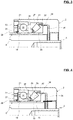
- FIG. 3 A second embodiment is illustrated in Figure 3 , wherein the same elements have the same references, and differs from the previous embodiment of Figure 1 in that a spacer 2a is axially interposed between the two angular contact bearings 19, 20 axially adjacent.
- Spacer 2a is inwardly radially projected from the inner bore 4 of housing 2 towards the axis X1. Said spacer 2 is axially in contact against the outer ring 21 of the angular contact ball bearing 19 on one axial side and axially in contact against the outer ring 27 of the angular contact roller bearing 19 on the other axial side.
- the spacer 2a is an annular ring mounted in said bore 4 of housing 2.
- FIG. 3 A third embodiment of the invention is illustrated in Figure 3 , wherein the same elements have the same references, and differs from the previous embodiment of Figure 1 in that the second angular contact bearing is an angular contact tapered roller bearing 35.
- First rolling bearing of the second embodiment is similar to the one of the first embodiment, and consists in the angular contact ball bearing 19.
- Angular contact tapered roller bearing 35 comprises an outer ring 36 with an outer tapered raceway 37, an inner ring 38 with an inner tapered raceway 39, and a row of tapered rollers 40 provided between said inner and outer raceways.
- Rollers 40 are carried and regularly circumferentially spaced by an annular cage 42.
- Rollers 40 are of matting shape with raceways 37, 39 and elongate along an inclined axis with respect to the central axis X1.
- Contact line between the raceways 37, 39 and the rollers 40 define an angle with the central axis X1.
- Angular contact ball bearing 19 and angular contact tapered roller bearing 35 are arranged radially between the bore 4 of housing 2 and the outer surface 26 of nut 6, similarly to bearings 19, 20 of the first embodiment illustrated in Figure 1 .
- Said bearings 19, 35 transmit axial loads in both directions from nut 6 to housing 2, similarly to the first embodiment.
- the advantage of an angular contact tapered roller bearing compared to an angular contact spherical roller bearing is that the contact area between the rollers and the raceways is reduced with tapered raceways. Friction is reduced with angular contact tapered roller bearing. Use of tapered roller bearing would also give other options in terms of bearing size for managing the compactness of the space envelope.
- an angular contact spherical roller bearing may be advantageous compared to an angular contact tapered roller bearing with this higher contact surface between the rollers and the spherical raceways, since such spherical roller bearing can support higher loads.
- An operator assembly 1 as shown in Figure 1 may be adapted for a gate valve 50 as illustrated in Figure 5 .
- Said gate valve 50 comprises a valve body with a bonnet 51, a valve housing (not shown in the appended drawing) covered by said bonnet and a moveable valve stem 52 of axis X52.
- the valve body has a flow bore and a transverse gate cavity that intersects the flow bore.
- the gate valve also comprises a gate having an opening extending transversely therethrough is disposed in the gate cavity.
- the bonnet 51 has a sealing function for the valve body and a fixing function between the gate valve 50 and the valve operator assembly 1.
- the valve operator assembly 1 comprises the tubular housing 2, an input member 53 rotatably mounted with respect to said housing, and a transmission mechanism 3 as described above.
- Transmission mechanism 3 is an inverted roller screws mechanism. Transmission mechanism 3 is mounted into the bore 4 of housing 2 and is connected to the input member 53 on one end and to the valve stem 52 of gate valve 50 on the other end.
- a connecting end 54 of valve stem 52 and a connecting end 55 of screw 5 of roller screw mechanism 3 are connected by any appropriate means, for example by threads, welding, glue, a clamp and/or a pin. Any movement of screw 5 is transmitted to the valve stem 52, in particular translating movement to open and close the gate cavity.
- Locking means 56 are radially mounted between the input member 54 and the nut 6. Locking means 56 transmits the rotational movement of said input member 54 to said nut 6, and then to actuate the roller screw mechanism 3. As illustrated in the embodiment of Figure 4 , said locking means 56 consist in a plurality of keys circumferentially distributed between recesses provided on an outer portion of the nut and recesses provided in an inner portion of the input member. Alternatively, said locking means may consist in an adapter sleeve axially arranged between said input member and nut or any other appropriate locking means.
- the roller screw mechanism 3 is then axially interposed between said input member 54 and said valve stem 52 to convert an input rotational motion of the input member 54 into an output axial motion of the valve stem 52.
- Two rolling bearings 19, 20 guide the rotation of the nut 6 of the roller screw mechanism 3 relative to the housing 2.
- the rolling bearings 19, 20 are radially mounted between the outer surface of the nut 6 and the stepped bore 4 of housing 2.
- Rolling bearings 19, 20 are axially adjacent.
- Rolling bearings 19, 20 define pressure cones with an O-arrangement.
- Rolling bearings consist in an angular contact ball bearing 19 and an angular contact spherical ball bearing 20 as described in the first embodiment and illustrated in Figures 2a and 2b .
- the angular contact ball bearing 19 is axially disposed on the side of the input member 53 and the angular contact spherical roller bearing 20 is axially disposed on the side of the bonnet 51 of valve body.
- the advantage of such bearing arrangement is that the angular contact spherical roller screw 20 is able to receive high loads in one given direction and is axially disposed on the side of direct axial loads exerted on the nut 6.
- the angular contact ball bearing 19 is able to receive axial loads in one given direction but of lower value than an angular contact roller bearing. Said angular contact ball bearing 19 is axially disposed on the side of reverse axial loads exerted on the nut 6 which are of lower value than the direct axial loads.
- FIG. 4 has been illustrated on the basis of a valve operator assembly for gate valve, it should be understood that the invention can also be used with other types of valves, for instance control or regulation valves or choke valves.
- the operator assembly may be used for instance with a surface gate or a subsea valve gate which may be actuated by a remote operating vehicle or an actuator.
- roller screw mechanism as transmission mechanism
- the invention can be applied without major modification to valve operator assembly using any other type of transmission mechanism, such as recirculating roller screw mechanism, ball screw mechanism, friction screw mechanism.
Abstract
Description
- The present invention relates to the fields of operator assembly comprising transmission mechanisms to be used in valves and manually operable valves, for instance gate valves, control or regulation valves or choke valves. More particularly, the invention relates to an operator assembly for a gate valve.
- Valves are used in a variety of industries to control the flow of fluids. In particular, gate valves are used extensively in the oil and gas industry to control the flow of produced fluids at various stages of drilling or production. Most gate valves used in this industry comprise a valve body having a longitudinal flow bore and a transverse gate cavity that intersects the flow bore. A gate having an opening extending transversely therethrough is disposed in the gate cavity. A valve stem is provided for moving the gate between an open position, in which the gate opening is aligned with the flow bore, and a closed position, in which the gate opening is offset from the flow bore. The gate cavity of the valve body is covered by a bonnet having an axial bore through which passes the valve stem.
- Such a gate valve is associated to a valve operator assembly for selectively driving the valve stem up and down in order to close and open the gate valve. A valve operator assembly generally comprises an input member to exert a rotational motion by a manual actuation by a hand-wheel or an electric or pneumatic or hydraulic actuation. The valve operator assembly further comprises a transmission mechanism to convert a rotational motion into axial motion of the valve stem. To quickly open and close the gate valve with a minimum number of turns, the transmission mechanism may be a screw mechanism, such as a roller screw mechanism, a ball screw mechanism or an acme screw with or without gear reducer, in order to reduce the operating torque.
- The transmission mechanism generally comprises a translating element connected to the valve stem and a rotating element connected to the input member, said transmission mechanisms being radially surrounded by a housing. Said rotating element may be supported in rotation and axially guided in the housing by rolling bearings.
- It is known to use a plurality of angular contact bearings to support in rotation and axially guiding the transmission mechanism in housing. For example, the patent applications
WO-A1-2012/087707 orWO-A1-2012/088008 describe valve operator assembly with two angular contact ball bearings. Said angular contact bearings in this prior art are axially arranged so as the pressure cones formed by the angular contact lines point radially outwardly from bearings. In other words, the angular contact bearings form an O-arrangement. The advantage of such bearings arrangement is to support axial load in both directions and to stabilize the inner rotating member. - However, the use of only two angular contact ball bearings may be not sufficient in most of the operator assembly applications. Contact surface of balls is not suitable for supporting high loads. Typically, gate valve applications require an arrangement of more than two angular contact ball bearings, for
instance 4 axially adjacent ball bearings. Such an operator assembly is not cost effective and not axially compact. Alternatively, a combination of radial and axial bearings can be used. - It is therefore a particular object of the present invention to overcome these aforementioned drawbacks by providing an operator assembly, in particular for valves, that supports and transmits axial and radial loads, of simple design, that is easy to assemble, economical, able to operate for a long time in both an effective and an economic manner.
- The invention concerns an operator assembly comprising a tubular housing extending along a central axis, and a transmission mechanism arranged in an inner bore of said housing and extending along said central axis. Said transmission mechanism comprises a screw with a threaded outer surface and a nut with a threaded inner surface, said nut being radially mounted around said screw, said inner thread being adapted to cooperate with outer thread of said screw. Angular contact bearings are radially arranged between the inner bore of said housing and an outer surface of said rotating nut to support in rotation and guide said nut within said housing.
- According to the invention, angular contact bearings are axially adjacent and comprise an angular contact ball bearing and an angular contact roller bearing. The angular contact ball bearing comprises an inner ring with a concave inner raceway, an outer ring with an concave outer raceway and a row of balls provided between said inner and outer raceways, said raceways being displaced with respect to each other in the direction of the central axis to define an angular contact line with the balls. The angular contact roller bearing comprises an inner ring with an inner raceway, an outer ring with an outer raceway, and a row of rollers provided between said inner and outer raceways, said raceways being inclined with respect to the central axis to define an angular contact line with the rollers. Angular contact lines of said bearings define respective pressure cones pointing radially outwardly from said bearings.
- According to further aspects of the invention, which are advantageous but not compulsory, such a valve operator assembly may incorporate one or several of the following features as long as there is no contradiction:
- The transmission mechanism is a roller screw mechanism wherein rollers are radially provided between the screw and the nut, said rollers comprising each an outer thread cooperating with the inner thread of the nut and with the outer thread of the screw.
- The transmission mechanism is a ball screw mechanism wherein balls are radially provided between the screw and the nut, said balls being arranged within the inner thread of the nut and with the outer thread of the screw.
- The operator assembly comprises a plurality of axially adjacent angular contact ball bearings, contact lines of said angular contact ball bearings being inclined in the same direction.
- The operator assembly comprises only one angular contact roller bearing.
- The angular contact roller bearing is axially maintained between an axial abutment provided on the outer surface of nut on one side and the angular contact ball bearing on the other side. The inner ring of said angular contact roller bearing axially abuts against said axial abutment of nut. The outer ring of said angular contact roller bearing axially abuts against the outer ring of said angular contact ball bearing.
- The angular contact ball bearing is axially maintained between an axial abutment provided in the bore of housing on one side and the angular contact roller bearing on the other side. The outer ring of said angular contact ball bearing axially abuts said axial abutment of housing on one side and axially abuts against the outer ring of said angular contact roller bearing on the other side.
- The inner ring of the angular contact ball bearing is force fitted on the outer surface of nut.
- Axial abutment provided in the bore of housing is a retaining ring secured with said bore by appropriate fixing means.
- Axial abutment provided in the bore of housing is a shoulder formed integrally with said housing.
- Axial abutment provided on the outer surface of nut is a shoulder formed integrally with said nut.
- Axial abutment provided on the outer surface of nut is a retaining ring secured with said outer surface by appropriate fixing means.
- The angular contact roller bearing consists in a tapered roller bearing, wherein the raceways are tapered.
- The angular contact roller bearing consists in a spherical roller bearing, wherein the raceways are spherical portions.
- A spacer is axially interposed between the outer rings of two axially adjacent angular contact bearings.
- The spacer is an annular ring mounted in the bore of housing.
- The spacer is an inwardly radially projecting step from the inner bore of housing.
- The invention also relates to a valve, notably a gate valve, a control or regulation valve or a choke valve comprising a valve body provided with a valve bonnet and a valve housing covered by said bonnet, a valve translating member axially moveable, an operator assembly according to any of the preceding embodiments, said valve translating element being fixed in translation to the translating screw of the transmission mechanism and said valve body being fixed to the housing of operator assembly, and an input member fixed in rotation to the rotating nut of the transmission mechanism.
- The valve translating member may be a valve stem or a piston for instance.
- As an embodiment, the input member is an operable hand-wheel. Alternatively, the input member is a mechanical operator or a remote operating vehicle.
- As an embodiment, the input member is directly connected to the rotating element to transmit rotational movement. Alternatively, an adapter sleeve or any appropriate locking means is mounted to secure the input member with the rotating nut.
- As an embodiment, the angular contact ball bearing is axially disposed on the side of the input member and the angular contact roller bearing is axially disposed on the side of the valve bonnet.
- The present invention and its advantages will be better understood by studying the detailed description of specific embodiments given by way of non-limiting examples and illustrated by the appended drawings on which:
-
Figure 1 is a sectional view of an operator assembly according to a first embodiment of the invention; -
Figure 2a and 2b are detailed sectional views of said operator assembly ofFigure 1 showing transmission of axial loads; -
Figure 3 is a detailed sectional view of an operator assembly according to a second embodiment of the invention; -
Figure 4 is a detailed sectional view of an operator assembly according to a third embodiment of the invention; and -
Figure 5 is a sectional view of a gate valve provided with an operator assembly according to the first embodiment of the invention. - In
Figure 1 , anoperator assembly 1, of central axis X1, comprises ahousing 2 and atransmission mechanism 3. Hereinafter, the adjectives "axial" and "radial" are defined relative to the central axis X1 of theoperator assembly 1. -
Housing 2 consists in a tubular cylinder provided with a steppedbore 4. Alternatively, thebore 4 may be cylindrical without any step.Housing 2 is centered to the central axis X1. -
Transmission mechanism 3 is radially arranged within thebore 4 ofhousing 2. In the embodiment illustrated inFigure 1 ,transmission mechanism 3 is a roller screw mechanism comprising ascrew 5, anut 6 androllers 7.Screw 5 is provided with a threadedouter surface 8. Thenut 6 is mounted coaxially about thescrew 5 and is provided with a threadedinner surface 9. A plurality oflongitudinal rollers 7 is disposed radially between thescrew 5 and thenut 6. - The
screw 5 extends longitudinally through a cylindrical bore of thenut 6 on which the threadedinner surface 9 is formed. Thenut 6 has a tubular form and is elongated to accommodate the full extent of screw travel. - The
rollers 7 are identical to each other and are distributed regularly around thescrew 5. Eachroller 7 extends along an axis which is parallel with the central axis X1 and comprises anouter thread 10 engaging thethread 9 of thenut 6 and thethread 8 of thescrew 5. Eachroller 7 also comprises, at each axial end,outer gear teeth 1 extending axially outwards theouter thread 10 and which are themselves extended axially by acylindrical stud 12 extending outwards. - The
outer gear teeth 11 are meshed byannular gear wheels 13 provided on the outer surface of thescrew 5. Each annular gear wheel is axially located near to an end of the threadedouter surface 8 ofscrew 5, said threadedouter surface 8 being axially located between saidgear wheels 13. - The
cylindrical studs 12 on axial ends of therollers 7 are housed in cylindrical through-recesses provided on spacer rings 14 (or annular guides). Spacer rings enable therollers 7 to be carried and the regular circumferential spacing thereof to be kept. The spacer rings 14 are radially disposed between thescrew 5 and the threadedinner surface 9 ofnut 6 without contacting with said thread. Eachspacer ring 14 is mounted on the outer surface of thescrew 5 axially next to an associatedgear wheel 13. The spacer rings 14 are hold on the outer surface of thescrew 5 by any appropriate means, here for example by aretainer ring 15 on one side and by ashoulder 16 on the axially opposite side. - In the embodiment of
Figure 1 , the threadedscrew 5 comprises ascrew connecting portion 17. Saidscrew connecting portion 17 is adapted to be secured to a first external element (not shown) and receive an input movement from said first external element. On the opposite axial side, the tubular cylindrical portion forming thenut 6 is closed on one end and extended by anut connecting portion 18. Saidnut connecting portion 18 is adapted to be secured to a second external element (not shown) and transmit an output movement to said external element. As one embodiment, an input rotational movement can be applied from the first external element to thescrew 5.Rollers 7 roll on theouter thread 8 ofscrew 5 and transmit movement to theinner thread 9 ofnut 6.Said nut 6 axially translates along the central axis X1 and transmits an output translating movement to the second external element. As another embodiment, an input translating movement can be applied from the first external element to thescrew 5.Rollers 7 roll on theouter thread 8 ofscrew 5 and transmit movement to theinner thread 9 ofnut 6.Said nut 6 rotates relatively to the central axis X1 and transmits an output rotating movement to the second external element. - Alternatively, and as it will be further described in the gate valve of
Figure 4 , said nut may be secured to said first external element and receives an input movement and said screw may be connected to said second external element and transmits an output movement. - The
valve operator assembly 1 further comprises two rollingbearings nut 6 of theroller screw mechanism 3 relative to thehousing 2. The rollingbearings nut 6 and the stepped bore 4 ofhousing 2.Rolling bearings - According to the invention, a first rolling bearing consists in an angular
contact ball bearing 19 comprising anouter ring 21 with a concaveouter raceway 22, aninner ring 23 with a concaveinner raceway 24 and a row ofballs 25 provided between said inner and outer raceways. Saidraceways balls 25 of angle A19 with said central axis X1. - Angular
contact ball bearing 19 is radially mounted between anouter surface 26 ofnut 6 and thebore 4 ofhousing 2. More precisely, theinner ring 23 defines an inner bore wherein saidouter surface 26 ofnut 6 is arranged. Theouter ring 21 defines an outer cylindrical surface fitted into saidbore 4 ofhousing 2. - A second rolling bearing consists in an angular contact
spherical roller bearing 20 comprising anouter ring 27 with an outerspherical raceway 28, aninner ring 29 with an innerspherical raceway 30, and a row ofrollers 31 provided between said inner and outer raceways.Rollers 31 are carried and regularly circumferentially spaced by anannular cage 32.Raceway 28 is spherical along a given radius R28 with respect to the central axis X1, as illustrated inFigure 2b .Raceway 30 is also spherical and symmetrical to saidspherical raceway 28 with respect torollers 31.Rollers 31 are of matting shape withraceways raceways rollers 31 define an angle A20 with the central axis X1. - Angular contact lines of said
bearings bearings - A retaining
ring 33 is secured in thebore 4 ofhousing 2 and axially bears against theouter ring 21 of angularcontact ball bearing 19. Said retainingring 33 comprises an outer thread engaged with a corresponding inner threaded portion provided in thebore 4 ofhousing 2. Axially on the opposite side, the angular contactspherical roller bearing 20 is axially mounted against ashoulder 34 provided on theouter surface 26 ofnut 6, saidshoulder 34 radially projecting towards the exterior of saidnut 6. Saidshoulder 34 axially retains theinner ring 29 of said angular contactspherical roller bearing 20 onnut 6.Shoulder 34 is integrally formed withnut 6. Alternatively, said shoulder may consist in a retaining ring secured to saidnut 6 by any appropriate means. In that case, the retainingring 33 ofhousing 2 may be replaced by a shoulder integrally formed with saidhousing 2 and radially projecting frombore 4 towards the central axis X1. -
Angular contact bearings contact ball bearing 19 is axially blocked between the retainingring 33 secured with thehousing 2 and the angular contactspherical roller bearing 20. Angular contactspherical roller bearing 20 is axially blocked between the angularcontact ball bearing 19 and theshoulder 34 protruding fromnut 6. More precisely, only the twoouter rings bearings outer ring 21 of angular contact ball bearing 19 forms an axial retainer for saidouter ring 27 of angular contactspherical ball bearing 20. - Thanks to the invention, the rolling
bearings nut 6 to thehousing 2. - As illustrated in the embodiment of
Figure 2a , an axial load F1 is exerted on thenut 6. Said load F1 is axially directed from theshoulder 34 towards theopposite end 18. Said load F1 is transmitted to thehousing 2 by theangular contact bearings shoulder 34 ofnut 6 to theinner ring 29 of angular contactspherical roller bearing 20. Said load is transmitted from saidinner ring 29 to theouter ring 27 throughrollers 31 of saidbearing 20 along the angular contact line of pressure cone P20. Said load is transmitted from saidouter ring 20 of the angular contactspherical roller bearing 20 to theouter ring 21 of the angularcontact ball bearing 19. Said load is transmitted from saidouter ring 21 of the angularcontact ball bearing 19 to the retainingring 33. Load is then transmitted to thehousing 2 from said retainingring 33 through the threaded portions of retainingring 33 and bore 4 ofhousing 2 in cooperation. - As illustrated in the embodiment of
Figure 2b , an axial load F2 is exerted on thenut 6 in the opposite direction of load F1. Said load F2 is transmitted to thehousing 2 by theangular contact bearings outer surface 26 ofnut 6 to theinner ring 23 of angularcontact ball bearing 19. Said load is transmitted from saidinner ring 23 to theouter ring 21 throughballs 25 of saidbearing 19 along the angular contact line of pressure cone P19. Said load is partly transmitted from saidouter ring 21 of the angularcontact ball bearing 19 to theouter ring 27 of the angular contactspherical roller bearing 20 and partly transmitted directly to thehousing 2. Residual load is finally transmitted from saidouter ring 27 of the angular contactspherical roller bearing 20 to thehousing 2. - Thanks to the invention, axial loads in both axial direction can be received and transmit by such a bearing arrangement. Moreover, and as it will be further described in
Figure 4 , the specific use of an angular contact ball bearing and an angular contact roller bearing (spherical bearing 19 as illustrated inFigures 2a and 2b or taperedbearing 35 as further illustrated inFigure 3 ) is suitable for applications wherein a high load is exerted in one given axial direction and to be received by the roller bearing, and a reduced load is exerted in the other axial direction and to be received by the ball bearing. - Another advantage is that only a fitted assembly is required to assemble said
bearings outer surface 26 ofnut 6 and into thebore 4 ofhousing 2. Said fitted assembly could be either a force or a loose fit. Advantageously, only twoaxial abutments axial abutment 34 against a front surface of theinner ring 29 of theroller bearing 20 and a secondaxial abutment 33 against a front surface of theouter ring 21 of theball bearing 19, theouter ring 27 of theroller bearing 20 and theouter ring 21 of theball bearing 19 being in axial abutment against each other. Ball and roller bearings form axial abutments for each other. - A second embodiment is illustrated in
Figure 3 , wherein the same elements have the same references, and differs from the previous embodiment ofFigure 1 in that aspacer 2a is axially interposed between the twoangular contact bearings -
Spacer 2a is inwardly radially projected from theinner bore 4 ofhousing 2 towards the axisX1. Said spacer 2 is axially in contact against theouter ring 21 of the angularcontact ball bearing 19 on one axial side and axially in contact against theouter ring 27 of the angularcontact roller bearing 19 on the other axial side. - As an alternate not shown, the
spacer 2a is an annular ring mounted in saidbore 4 ofhousing 2. - A third embodiment of the invention is illustrated in
Figure 3 , wherein the same elements have the same references, and differs from the previous embodiment ofFigure 1 in that the second angular contact bearing is an angular contact taperedroller bearing 35. - First rolling bearing of the second embodiment is similar to the one of the first embodiment, and consists in the angular
contact ball bearing 19. - Angular contact tapered
roller bearing 35 comprises anouter ring 36 with an outertapered raceway 37, aninner ring 38 with an innertapered raceway 39, and a row of taperedrollers 40 provided between said inner and outer raceways.Rollers 40 are carried and regularly circumferentially spaced by anannular cage 42.Rollers 40 are of matting shape withraceways raceways rollers 40 define an angle with the central axis X1. - Angular
contact ball bearing 19 and angular contact taperedroller bearing 35 are arranged radially between thebore 4 ofhousing 2 and theouter surface 26 ofnut 6, similarly tobearings Figure 1 . Saidbearings nut 6 tohousing 2, similarly to the first embodiment. - In some applications, the advantage of an angular contact tapered roller bearing compared to an angular contact spherical roller bearing is that the contact area between the rollers and the raceways is reduced with tapered raceways. Friction is reduced with angular contact tapered roller bearing. Use of tapered roller bearing would also give other options in terms of bearing size for managing the compactness of the space envelope.
- Alternatively, an angular contact spherical roller bearing may be advantageous compared to an angular contact tapered roller bearing with this higher contact surface between the rollers and the spherical raceways, since such spherical roller bearing can support higher loads.
- An
operator assembly 1 as shown inFigure 1 may be adapted for agate valve 50 as illustrated inFigure 5 . Saidgate valve 50 comprises a valve body with abonnet 51, a valve housing (not shown in the appended drawing) covered by said bonnet and a moveable valve stem 52 of axis X52. Conventionally, the valve body has a flow bore and a transverse gate cavity that intersects the flow bore. The gate valve also comprises a gate having an opening extending transversely therethrough is disposed in the gate cavity. Thebonnet 51 has a sealing function for the valve body and a fixing function between thegate valve 50 and thevalve operator assembly 1. - The
valve operator assembly 1 comprises thetubular housing 2, aninput member 53 rotatably mounted with respect to said housing, and atransmission mechanism 3 as described above.Transmission mechanism 3 is an inverted roller screws mechanism.Transmission mechanism 3 is mounted into thebore 4 ofhousing 2 and is connected to theinput member 53 on one end and to thevalve stem 52 ofgate valve 50 on the other end. - Axially on the side opposite to the
input member 6, a connectingend 54 ofvalve stem 52 and a connectingend 55 ofscrew 5 ofroller screw mechanism 3 are connected by any appropriate means, for example by threads, welding, glue, a clamp and/or a pin. Any movement ofscrew 5 is transmitted to thevalve stem 52, in particular translating movement to open and close the gate cavity. - Locking means 56 are radially mounted between the
input member 54 and thenut 6. Locking means 56 transmits the rotational movement of saidinput member 54 to saidnut 6, and then to actuate theroller screw mechanism 3. As illustrated in the embodiment ofFigure 4 , said locking means 56 consist in a plurality of keys circumferentially distributed between recesses provided on an outer portion of the nut and recesses provided in an inner portion of the input member. Alternatively, said locking means may consist in an adapter sleeve axially arranged between said input member and nut or any other appropriate locking means. - The
roller screw mechanism 3 is then axially interposed between saidinput member 54 and said valve stem 52 to convert an input rotational motion of theinput member 54 into an output axial motion of thevalve stem 52. - Two rolling
bearings nut 6 of theroller screw mechanism 3 relative to thehousing 2. The rollingbearings nut 6 and the stepped bore 4 ofhousing 2.Rolling bearings Rolling bearings contact ball bearing 19 and an angular contactspherical ball bearing 20 as described in the first embodiment and illustrated inFigures 2a and 2b . - In this embodiment, the angular
contact ball bearing 19 is axially disposed on the side of theinput member 53 and the angular contactspherical roller bearing 20 is axially disposed on the side of thebonnet 51 of valve body. - The advantage of such bearing arrangement is that the angular contact
spherical roller screw 20 is able to receive high loads in one given direction and is axially disposed on the side of direct axial loads exerted on thenut 6. The angularcontact ball bearing 19 is able to receive axial loads in one given direction but of lower value than an angular contact roller bearing. Said angularcontact ball bearing 19 is axially disposed on the side of reverse axial loads exerted on thenut 6 which are of lower value than the direct axial loads. - The installation of two angular contact roller bearings is prevented since such an arrangement is expensive, require a specific design of the housing and the outer surface of the nut to maintain the rings, and induce a very high friction torque. The arrangement of an angular contact ball bearing with an angular contact roller bearing permits to support direct loads and reverse loads in both axial directions with a ball bearing of reduced cost and providing a limited friction torque. Moreover, higher load capacity is supported in a compact space envelope.
- Although the embodiment of
Figure 4 has been illustrated on the basis of a valve operator assembly for gate valve, it should be understood that the invention can also be used with other types of valves, for instance control or regulation valves or choke valves. The operator assembly may be used for instance with a surface gate or a subsea valve gate which may be actuated by a remote operating vehicle or an actuator. - Although the present invention has been illustrated using a roller screw mechanism as transmission mechanism, it will be understood that the invention can be applied without major modification to valve operator assembly using any other type of transmission mechanism, such as recirculating roller screw mechanism, ball screw mechanism, friction screw mechanism.
- The embodiments disclosed in the description may be arranged or combined together and are still within the meaning of the present invention.
Claims (10)
- Operator assembly (1) comprising:- a tubular housing (2) extending along a central axis (X1),- a transmission mechanism (3) arranged in an inner bore (4) of said housing (2) and extending along said central axis (X1), said transmission mechanism (3) comprising a screw (5) with a threaded outer surface (8) and a nut (6) with a threaded inner surface (9), said nut (6) being radially mounted around said screw (5) and said inner thread (9) being adapted to cooperate with outer thread (8), and- angular contact bearings (19, 20; 35) are radially arranged between the inner bore (4) of said housing (2) and an outer surface (26) of said rotating nut (6) to support in rotation and guide said nut (6) within said housing (2),characterized in that angular contact bearings (19, 20; 35) are axially adjacent and comprise:- an angular contact ball bearing (19) comprising an inner ring (23) with a concave inner raceway (24), an outer ring (21) with an concave outer raceway (22) and a row of balls (25) provided between said inner (24) and outer (22) raceways, said raceways (22, 24) being displaced with respect to each other in the direction of the central axis (X1) to define an angular contact line (P19) with the balls (25), and- an angular contact roller bearing (20, 35) comprising an inner ring (29, 38) with an inner raceway (30, 39), an outer ring (27, 36) with an outer raceway (28, 37), and a row of rollers (31, 40) provided between said inner (30, 39) and outer (28, 37) raceways, said raceways (30, 28; 39, 37) being inclined with respect to the central axis (X1) to define an angular contact line (P20) with the rollers (31, 40),said angular contact lines of said bearings (19, 20; 35) defining respective pressure cones (P19, P20) pointing radially outwardly from said bearings (19, 20; 35).
- Operator assembly according to claim 1, wherein the angular contact roller bearing (20) is axially maintained between an axial abutment (34) provided on the outer surface (26) of nut (6) on one side and the angular contact ball bearing (19) on the other side, the inner ring (29) of said angular contact roller bearing (20) being in axial abutment against said axial abutment (34) of nut (6) and the outer ring (27) of said angular contact roller bearing (20) being in axial abutment against the outer ring (21) of said angular contact ball bearing (19).
- Operator assembly according to claim 2, wherein the axial abutment provided on the outer surface (26) of nut (6) is a shoulder (34) formed integrally with said nut (6).
- Operator assembly according to any of the preceding claims, wherein the angular contact ball bearing (19) is axially maintained between an axial abutment (33) provided in the bore (4) of housing (2) on one side and the angular contact roller bearing (20) on the other side, the outer ring (21) of said angular contact ball bearing (19) being in axial abutment against said axial abutment (33) of housing (2) on one side and in axial abutment against the outer ring (27) of said angular contact roller bearing (19) on the other side.
- Operator assembly according to claim 4, wherein the axial abutment provided in the bore (4) of housing (2) is a retaining ring (33) secured with said bore (4) by appropriate fixing means.
- Operator assembly according to any of the preceding claims, wherein the angular contact roller bearing consists in a tapered roller bearing (35), wherein the raceways (37, 38) are tapered.
- Operator assembly according to any of the preceding claims, wherein the angular contact roller bearing consists in a spherical roller bearing (20), wherein the raceways (28, 30) are spherical portions.
- Operator assembly according to any of the preceding claims, wherein it comprises a plurality of axially adjacent angular contact ball bearings (19), contact lines of said angular contact ball bearings being inclined in the same direction, and only one angular contact roller bearing (20, 35).
- Valve (50), notably a gate valve, a control or regulation valve or a choke valve comprising a valve body provided with a valve bonnet (51) and a valve housing covered by said bonnet (51), a valve translating member (52) axially moveable, an operator assembly (1) according to any of the preceding claims, said valve translating element (52) being fixed in translation to the translating screw (5) of the transmission mechanism (3) and said valve body being fixed to the housing (2) of operator assembly (1), and an input member (53) is fixed in rotation to the rotating nut (6) of the transmission mechanism (3).
- Valve according to claim 9, wherein the angular contact ball bearing (19) is axially disposed on the side of the input member (53) and the angular contact roller bearing (20) is axially disposed on the side of the valve body.
Applications Claiming Priority (1)
| Application Number | Priority Date | Filing Date | Title |
|---|---|---|---|
| DE102016209061 | 2016-05-25 |
Publications (1)
| Publication Number | Publication Date |
|---|---|
| EP3249272A1 true EP3249272A1 (en) | 2017-11-29 |
Family
ID=58669644
Family Applications (1)
| Application Number | Title | Priority Date | Filing Date |
|---|---|---|---|
| EP17169062.1A Withdrawn EP3249272A1 (en) | 2016-05-25 | 2017-05-02 | Operator assembly and valve equipped with such assembly |
Country Status (3)
| Country | Link |
|---|---|
| US (1) | US10550955B2 (en) |
| EP (1) | EP3249272A1 (en) |
| CN (1) | CN107435756A (en) |
Families Citing this family (3)
| Publication number | Priority date | Publication date | Assignee | Title |
|---|---|---|---|---|
| CN107966291B (en) * | 2017-12-29 | 2024-03-05 | 贵州大学 | Pressure relief valve detects revolving stage |
| CN108838643A (en) * | 2018-08-24 | 2018-11-20 | 博众精工科技股份有限公司 | Rotating mechanism and motor assembling device |
| CN109595228B (en) * | 2019-01-11 | 2020-06-16 | 哈尔滨工程大学 | Installation and separator of ball valve executor under water |
Citations (5)
| Publication number | Priority date | Publication date | Assignee | Title |
|---|---|---|---|---|
| EP1745221B1 (en) * | 2004-05-07 | 2008-10-15 | The Timken Company | Locating bearing assembly for wind turbine gearbox shaft |
| DE102007055362A1 (en) * | 2007-11-20 | 2009-05-28 | Schaeffler Kg | Rolling bearing for a wave-shaped component |
| WO2012087707A1 (en) | 2010-12-20 | 2012-06-28 | Aktiebolaget Skf | Lockable drive assembly for rotatable members |
| WO2012088008A1 (en) | 2010-12-20 | 2012-06-28 | Aktiebolaget Skf | Valve operatior assembly with anti-backdriving device |
| WO2016019983A1 (en) * | 2014-08-05 | 2016-02-11 | Aktiebolaget Skf | Valve operator assembly, valve equipped with such assembly and assembly process for such a valve |
Family Cites Families (15)
| Publication number | Priority date | Publication date | Assignee | Title |
|---|---|---|---|---|
| JPS5338847A (en) * | 1976-09-21 | 1978-04-10 | Ntn Toyo Bearing Co Ltd | Bearing pre-pressure regulating method |
| DE2911479C2 (en) * | 1979-03-22 | 1983-09-29 | Lechler, Gerhard, Dr.-Ing., 1000 Berlin | Force measuring device |
| US6277492B1 (en) * | 1998-07-06 | 2001-08-21 | Visteon Global Technologies, Inc. | Providing organic paint on glass to match automotive body color |
| JP2004019772A (en) * | 2002-06-14 | 2004-01-22 | Fuji Heavy Ind Ltd | Compound bearing assembly and gear transmission using it |
| US7303180B1 (en) | 2006-12-18 | 2007-12-04 | Val Matic Valve & Mfg. Corp. | Valve actuator with split thrust bearing |
| CN100494755C (en) * | 2007-04-16 | 2009-06-03 | 袁平仁 | Manually operated mechanism of linear motion regulating valve |
| US7703746B2 (en) * | 2007-07-12 | 2010-04-27 | Roller Bearing Company Of America, Inc. | Ground-based power generator with ball-roller bearing butterfly valve |
| DE102007049982A1 (en) * | 2007-10-18 | 2009-04-23 | Knorr-Bremse Systeme für Nutzfahrzeuge GmbH | Rolling bearings, in particular for the storage of a commercial vehicle wheel |
| DE102010008434A1 (en) * | 2010-02-18 | 2011-08-18 | Schaeffler Technologies GmbH & Co. KG, 91074 | Multi-row ball bearing has tapered roller bearing which comprises conical inner bearing surface and conical outer bearing surface |
| DE102011003705A1 (en) * | 2011-02-07 | 2012-08-09 | Schaeffler Technologies Gmbh & Co. Kg | Bearing arrangement for bevel gear shaft, has angular contact ball bearing including outer ring that is inserted into outer sleeve with outer tracks for balls, where outer sleeve comprises annular space for retaining outer ring |
| CN104968974A (en) * | 2013-02-25 | 2015-10-07 | 爱信艾达株式会社 | Dynamic force transmission device |
| JP6210485B2 (en) * | 2013-06-28 | 2017-10-11 | 並木精密宝石株式会社 | Bearing mechanism |
| US9593756B2 (en) * | 2013-07-31 | 2017-03-14 | American Axle & Manufacturing, Inc. | Bearing assembly configured to handle axial and radial loads |
| DE102013215554B3 (en) * | 2013-08-07 | 2014-11-27 | Aktiebolaget Skf | bearing arrangement |
| GB2534768B (en) * | 2013-11-21 | 2020-01-22 | Skf Ab | Valve operator assembly with freewheel and axial friction means |
-
2017
- 2017-05-02 EP EP17169062.1A patent/EP3249272A1/en not_active Withdrawn
- 2017-05-11 CN CN201710329997.9A patent/CN107435756A/en not_active Withdrawn
- 2017-05-18 US US15/598,957 patent/US10550955B2/en not_active Expired - Fee Related
Patent Citations (5)
| Publication number | Priority date | Publication date | Assignee | Title |
|---|---|---|---|---|
| EP1745221B1 (en) * | 2004-05-07 | 2008-10-15 | The Timken Company | Locating bearing assembly for wind turbine gearbox shaft |
| DE102007055362A1 (en) * | 2007-11-20 | 2009-05-28 | Schaeffler Kg | Rolling bearing for a wave-shaped component |
| WO2012087707A1 (en) | 2010-12-20 | 2012-06-28 | Aktiebolaget Skf | Lockable drive assembly for rotatable members |
| WO2012088008A1 (en) | 2010-12-20 | 2012-06-28 | Aktiebolaget Skf | Valve operatior assembly with anti-backdriving device |
| WO2016019983A1 (en) * | 2014-08-05 | 2016-02-11 | Aktiebolaget Skf | Valve operator assembly, valve equipped with such assembly and assembly process for such a valve |
Also Published As
| Publication number | Publication date |
|---|---|
| US10550955B2 (en) | 2020-02-04 |
| US20170343129A1 (en) | 2017-11-30 |
| CN107435756A (en) | 2017-12-05 |
Similar Documents
| Publication | Publication Date | Title |
|---|---|---|
| US10584777B2 (en) | Roller screw mechanism with cage | |
| US20160186887A1 (en) | Valve operator assembly with inverted roller screw | |
| US9752701B2 (en) | Valve operator assembly with freewheel and axial friction means | |
| US10550955B2 (en) | Operator assembly and valve equipped with such assembly | |
| EP3324089B1 (en) | Valve operator assembly with clutch mechanism and valve equipped with such assembly | |
| US20160146319A1 (en) | Non back-driveable screw mechanism | |
| US10060550B2 (en) | Valve operator assembly with friction means and pre-stressing element | |
| US20170335991A1 (en) | Valve operator assembly with freewheel and friction means | |
| EP3022473B1 (en) | Valve operator assembly with compensating actuator | |
| US20170241564A1 (en) | Valve operator assembly, valve equipped with such assembly and assembly process for such a valve | |
| WO2015074699A1 (en) | Valve operator assembly with freewheel and friction means | |
| EP3262328B1 (en) | Valve operator assembly with double screw mechanism and operable wheel | |
| EP3262329B1 (en) | Valve operator assembly with operable wheel | |
| US10436347B2 (en) | Valve operator assembly with double screw mechanism | |
| US10041604B2 (en) | Valve operator assembly and valve equipped with such assembly | |
| WO2016078688A1 (en) | Valve operator assembly with variable lead | |
| WO2016078689A1 (en) | Valve operator assembly with anti-rotation means | |
| WO2016078687A1 (en) | Screw nut assembly |
Legal Events
| Date | Code | Title | Description |
|---|---|---|---|
| PUAI | Public reference made under article 153(3) epc to a published international application that has entered the european phase |
Free format text: ORIGINAL CODE: 0009012 |
|
| AK | Designated contracting states |
Kind code of ref document: A1 Designated state(s): AL AT BE BG CH CY CZ DE DK EE ES FI FR GB GR HR HU IE IS IT LI LT LU LV MC MK MT NL NO PL PT RO RS SE SI SK SM TR |
|
| AX | Request for extension of the european patent |
Extension state: BA ME |
|
| 17P | Request for examination filed |
Effective date: 20171220 |
|
| RBV | Designated contracting states (corrected) |
Designated state(s): AL AT BE BG CH CY CZ DE DK EE ES FI FR GB GR HR HU IE IS IT LI LT LU LV MC MK MT NL NO PL PT RO RS SE SI SK SM TR |
|
| STAA | Information on the status of an ep patent application or granted ep patent |
Free format text: STATUS: THE APPLICATION IS DEEMED TO BE WITHDRAWN |
|
| 18D | Application deemed to be withdrawn |
Effective date: 20180530 |