EP3249191A1 - Exhaust gas purification system and method for a work vehicle - Google Patents
Exhaust gas purification system and method for a work vehicle Download PDFInfo
- Publication number
- EP3249191A1 EP3249191A1 EP17172885.0A EP17172885A EP3249191A1 EP 3249191 A1 EP3249191 A1 EP 3249191A1 EP 17172885 A EP17172885 A EP 17172885A EP 3249191 A1 EP3249191 A1 EP 3249191A1
- Authority
- EP
- European Patent Office
- Prior art keywords
- exhaust gas
- gas purification
- work vehicle
- control mode
- purification system
- Prior art date
- Legal status (The legal status is an assumption and is not a legal conclusion. Google has not performed a legal analysis and makes no representation as to the accuracy of the status listed.)
- Granted
Links
Images

Classifications
-
- F—MECHANICAL ENGINEERING; LIGHTING; HEATING; WEAPONS; BLASTING
- F01—MACHINES OR ENGINES IN GENERAL; ENGINE PLANTS IN GENERAL; STEAM ENGINES
- F01N—GAS-FLOW SILENCERS OR EXHAUST APPARATUS FOR MACHINES OR ENGINES IN GENERAL; GAS-FLOW SILENCERS OR EXHAUST APPARATUS FOR INTERNAL-COMBUSTION ENGINES
- F01N3/00—Exhaust or silencing apparatus having means for purifying, rendering innocuous, or otherwise treating exhaust
- F01N3/08—Exhaust or silencing apparatus having means for purifying, rendering innocuous, or otherwise treating exhaust for rendering innocuous
- F01N3/10—Exhaust or silencing apparatus having means for purifying, rendering innocuous, or otherwise treating exhaust for rendering innocuous by thermal or catalytic conversion of noxious components of exhaust
- F01N3/18—Exhaust or silencing apparatus having means for purifying, rendering innocuous, or otherwise treating exhaust for rendering innocuous by thermal or catalytic conversion of noxious components of exhaust characterised by methods of operation; Control
- F01N3/20—Exhaust or silencing apparatus having means for purifying, rendering innocuous, or otherwise treating exhaust for rendering innocuous by thermal or catalytic conversion of noxious components of exhaust characterised by methods of operation; Control specially adapted for catalytic conversion
- F01N3/206—Adding periodically or continuously substances to exhaust gases for promoting purification, e.g. catalytic material in liquid form, NOx reducing agents
- F01N3/208—Control of selective catalytic reduction [SCR], e.g. by adjusting the dosing of reducing agent
-
- F—MECHANICAL ENGINEERING; LIGHTING; HEATING; WEAPONS; BLASTING
- F01—MACHINES OR ENGINES IN GENERAL; ENGINE PLANTS IN GENERAL; STEAM ENGINES
- F01N—GAS-FLOW SILENCERS OR EXHAUST APPARATUS FOR MACHINES OR ENGINES IN GENERAL; GAS-FLOW SILENCERS OR EXHAUST APPARATUS FOR INTERNAL-COMBUSTION ENGINES
- F01N11/00—Monitoring or diagnostic devices for exhaust-gas treatment apparatus
-
- F—MECHANICAL ENGINEERING; LIGHTING; HEATING; WEAPONS; BLASTING
- F01—MACHINES OR ENGINES IN GENERAL; ENGINE PLANTS IN GENERAL; STEAM ENGINES
- F01N—GAS-FLOW SILENCERS OR EXHAUST APPARATUS FOR MACHINES OR ENGINES IN GENERAL; GAS-FLOW SILENCERS OR EXHAUST APPARATUS FOR INTERNAL-COMBUSTION ENGINES
- F01N3/00—Exhaust or silencing apparatus having means for purifying, rendering innocuous, or otherwise treating exhaust
- F01N3/08—Exhaust or silencing apparatus having means for purifying, rendering innocuous, or otherwise treating exhaust for rendering innocuous
- F01N3/10—Exhaust or silencing apparatus having means for purifying, rendering innocuous, or otherwise treating exhaust for rendering innocuous by thermal or catalytic conversion of noxious components of exhaust
- F01N3/18—Exhaust or silencing apparatus having means for purifying, rendering innocuous, or otherwise treating exhaust for rendering innocuous by thermal or catalytic conversion of noxious components of exhaust characterised by methods of operation; Control
- F01N3/20—Exhaust or silencing apparatus having means for purifying, rendering innocuous, or otherwise treating exhaust for rendering innocuous by thermal or catalytic conversion of noxious components of exhaust characterised by methods of operation; Control specially adapted for catalytic conversion
- F01N3/206—Adding periodically or continuously substances to exhaust gases for promoting purification, e.g. catalytic material in liquid form, NOx reducing agents
- F01N3/2066—Selective catalytic reduction [SCR]
-
- F—MECHANICAL ENGINEERING; LIGHTING; HEATING; WEAPONS; BLASTING
- F01—MACHINES OR ENGINES IN GENERAL; ENGINE PLANTS IN GENERAL; STEAM ENGINES
- F01N—GAS-FLOW SILENCERS OR EXHAUST APPARATUS FOR MACHINES OR ENGINES IN GENERAL; GAS-FLOW SILENCERS OR EXHAUST APPARATUS FOR INTERNAL-COMBUSTION ENGINES
- F01N9/00—Electrical control of exhaust gas treating apparatus
-
- F—MECHANICAL ENGINEERING; LIGHTING; HEATING; WEAPONS; BLASTING
- F01—MACHINES OR ENGINES IN GENERAL; ENGINE PLANTS IN GENERAL; STEAM ENGINES
- F01N—GAS-FLOW SILENCERS OR EXHAUST APPARATUS FOR MACHINES OR ENGINES IN GENERAL; GAS-FLOW SILENCERS OR EXHAUST APPARATUS FOR INTERNAL-COMBUSTION ENGINES
- F01N2550/00—Monitoring or diagnosing the deterioration of exhaust systems
- F01N2550/05—Systems for adding substances into exhaust
-
- F—MECHANICAL ENGINEERING; LIGHTING; HEATING; WEAPONS; BLASTING
- F01—MACHINES OR ENGINES IN GENERAL; ENGINE PLANTS IN GENERAL; STEAM ENGINES
- F01N—GAS-FLOW SILENCERS OR EXHAUST APPARATUS FOR MACHINES OR ENGINES IN GENERAL; GAS-FLOW SILENCERS OR EXHAUST APPARATUS FOR INTERNAL-COMBUSTION ENGINES
- F01N2560/00—Exhaust systems with means for detecting or measuring exhaust gas components or characteristics
- F01N2560/07—Exhaust systems with means for detecting or measuring exhaust gas components or characteristics the means being an exhaust gas flow rate or velocity meter or sensor, intake flow meters only when exclusively used to determine exhaust gas parameters
-
- F—MECHANICAL ENGINEERING; LIGHTING; HEATING; WEAPONS; BLASTING
- F01—MACHINES OR ENGINES IN GENERAL; ENGINE PLANTS IN GENERAL; STEAM ENGINES
- F01N—GAS-FLOW SILENCERS OR EXHAUST APPARATUS FOR MACHINES OR ENGINES IN GENERAL; GAS-FLOW SILENCERS OR EXHAUST APPARATUS FOR INTERNAL-COMBUSTION ENGINES
- F01N2590/00—Exhaust or silencing apparatus adapted to particular use, e.g. for military applications, airplanes, submarines
- F01N2590/08—Exhaust or silencing apparatus adapted to particular use, e.g. for military applications, airplanes, submarines for heavy duty applications, e.g. trucks, buses, tractors, locomotives
-
- F—MECHANICAL ENGINEERING; LIGHTING; HEATING; WEAPONS; BLASTING
- F01—MACHINES OR ENGINES IN GENERAL; ENGINE PLANTS IN GENERAL; STEAM ENGINES
- F01N—GAS-FLOW SILENCERS OR EXHAUST APPARATUS FOR MACHINES OR ENGINES IN GENERAL; GAS-FLOW SILENCERS OR EXHAUST APPARATUS FOR INTERNAL-COMBUSTION ENGINES
- F01N2610/00—Adding substances to exhaust gases
- F01N2610/01—Adding substances to exhaust gases the substance being catalytic material in liquid form
-
- F—MECHANICAL ENGINEERING; LIGHTING; HEATING; WEAPONS; BLASTING
- F01—MACHINES OR ENGINES IN GENERAL; ENGINE PLANTS IN GENERAL; STEAM ENGINES
- F01N—GAS-FLOW SILENCERS OR EXHAUST APPARATUS FOR MACHINES OR ENGINES IN GENERAL; GAS-FLOW SILENCERS OR EXHAUST APPARATUS FOR INTERNAL-COMBUSTION ENGINES
- F01N2610/00—Adding substances to exhaust gases
- F01N2610/02—Adding substances to exhaust gases the substance being ammonia or urea
-
- F—MECHANICAL ENGINEERING; LIGHTING; HEATING; WEAPONS; BLASTING
- F01—MACHINES OR ENGINES IN GENERAL; ENGINE PLANTS IN GENERAL; STEAM ENGINES
- F01N—GAS-FLOW SILENCERS OR EXHAUST APPARATUS FOR MACHINES OR ENGINES IN GENERAL; GAS-FLOW SILENCERS OR EXHAUST APPARATUS FOR INTERNAL-COMBUSTION ENGINES
- F01N2610/00—Adding substances to exhaust gases
- F01N2610/14—Arrangements for the supply of substances, e.g. conduits
- F01N2610/1433—Pumps
-
- F—MECHANICAL ENGINEERING; LIGHTING; HEATING; WEAPONS; BLASTING
- F01—MACHINES OR ENGINES IN GENERAL; ENGINE PLANTS IN GENERAL; STEAM ENGINES
- F01N—GAS-FLOW SILENCERS OR EXHAUST APPARATUS FOR MACHINES OR ENGINES IN GENERAL; GAS-FLOW SILENCERS OR EXHAUST APPARATUS FOR INTERNAL-COMBUSTION ENGINES
- F01N2610/00—Adding substances to exhaust gases
- F01N2610/14—Arrangements for the supply of substances, e.g. conduits
- F01N2610/1433—Pumps
- F01N2610/144—Control thereof
-
- F—MECHANICAL ENGINEERING; LIGHTING; HEATING; WEAPONS; BLASTING
- F01—MACHINES OR ENGINES IN GENERAL; ENGINE PLANTS IN GENERAL; STEAM ENGINES
- F01N—GAS-FLOW SILENCERS OR EXHAUST APPARATUS FOR MACHINES OR ENGINES IN GENERAL; GAS-FLOW SILENCERS OR EXHAUST APPARATUS FOR INTERNAL-COMBUSTION ENGINES
- F01N2610/00—Adding substances to exhaust gases
- F01N2610/14—Arrangements for the supply of substances, e.g. conduits
- F01N2610/1453—Sprayers or atomisers; Arrangement thereof in the exhaust apparatus
-
- F—MECHANICAL ENGINEERING; LIGHTING; HEATING; WEAPONS; BLASTING
- F01—MACHINES OR ENGINES IN GENERAL; ENGINE PLANTS IN GENERAL; STEAM ENGINES
- F01N—GAS-FLOW SILENCERS OR EXHAUST APPARATUS FOR MACHINES OR ENGINES IN GENERAL; GAS-FLOW SILENCERS OR EXHAUST APPARATUS FOR INTERNAL-COMBUSTION ENGINES
- F01N2610/00—Adding substances to exhaust gases
- F01N2610/14—Arrangements for the supply of substances, e.g. conduits
- F01N2610/1453—Sprayers or atomisers; Arrangement thereof in the exhaust apparatus
- F01N2610/146—Control thereof, e.g. control of injectors or injection valves
-
- F—MECHANICAL ENGINEERING; LIGHTING; HEATING; WEAPONS; BLASTING
- F01—MACHINES OR ENGINES IN GENERAL; ENGINE PLANTS IN GENERAL; STEAM ENGINES
- F01N—GAS-FLOW SILENCERS OR EXHAUST APPARATUS FOR MACHINES OR ENGINES IN GENERAL; GAS-FLOW SILENCERS OR EXHAUST APPARATUS FOR INTERNAL-COMBUSTION ENGINES
- F01N2610/00—Adding substances to exhaust gases
- F01N2610/14—Arrangements for the supply of substances, e.g. conduits
- F01N2610/1493—Purging the reducing agent out of the conduits or nozzle
-
- F—MECHANICAL ENGINEERING; LIGHTING; HEATING; WEAPONS; BLASTING
- F01—MACHINES OR ENGINES IN GENERAL; ENGINE PLANTS IN GENERAL; STEAM ENGINES
- F01N—GAS-FLOW SILENCERS OR EXHAUST APPARATUS FOR MACHINES OR ENGINES IN GENERAL; GAS-FLOW SILENCERS OR EXHAUST APPARATUS FOR INTERNAL-COMBUSTION ENGINES
- F01N2900/00—Details of electrical control or of the monitoring of the exhaust gas treating apparatus
- F01N2900/04—Methods of control or diagnosing
-
- F—MECHANICAL ENGINEERING; LIGHTING; HEATING; WEAPONS; BLASTING
- F01—MACHINES OR ENGINES IN GENERAL; ENGINE PLANTS IN GENERAL; STEAM ENGINES
- F01N—GAS-FLOW SILENCERS OR EXHAUST APPARATUS FOR MACHINES OR ENGINES IN GENERAL; GAS-FLOW SILENCERS OR EXHAUST APPARATUS FOR INTERNAL-COMBUSTION ENGINES
- F01N2900/00—Details of electrical control or of the monitoring of the exhaust gas treating apparatus
- F01N2900/06—Parameters used for exhaust control or diagnosing
-
- F—MECHANICAL ENGINEERING; LIGHTING; HEATING; WEAPONS; BLASTING
- F01—MACHINES OR ENGINES IN GENERAL; ENGINE PLANTS IN GENERAL; STEAM ENGINES
- F01N—GAS-FLOW SILENCERS OR EXHAUST APPARATUS FOR MACHINES OR ENGINES IN GENERAL; GAS-FLOW SILENCERS OR EXHAUST APPARATUS FOR INTERNAL-COMBUSTION ENGINES
- F01N2900/00—Details of electrical control or of the monitoring of the exhaust gas treating apparatus
- F01N2900/06—Parameters used for exhaust control or diagnosing
- F01N2900/08—Parameters used for exhaust control or diagnosing said parameters being related to the engine
-
- F—MECHANICAL ENGINEERING; LIGHTING; HEATING; WEAPONS; BLASTING
- F01—MACHINES OR ENGINES IN GENERAL; ENGINE PLANTS IN GENERAL; STEAM ENGINES
- F01N—GAS-FLOW SILENCERS OR EXHAUST APPARATUS FOR MACHINES OR ENGINES IN GENERAL; GAS-FLOW SILENCERS OR EXHAUST APPARATUS FOR INTERNAL-COMBUSTION ENGINES
- F01N2900/00—Details of electrical control or of the monitoring of the exhaust gas treating apparatus
- F01N2900/06—Parameters used for exhaust control or diagnosing
- F01N2900/10—Parameters used for exhaust control or diagnosing said parameters being related to the vehicle or its components
-
- F—MECHANICAL ENGINEERING; LIGHTING; HEATING; WEAPONS; BLASTING
- F01—MACHINES OR ENGINES IN GENERAL; ENGINE PLANTS IN GENERAL; STEAM ENGINES
- F01N—GAS-FLOW SILENCERS OR EXHAUST APPARATUS FOR MACHINES OR ENGINES IN GENERAL; GAS-FLOW SILENCERS OR EXHAUST APPARATUS FOR INTERNAL-COMBUSTION ENGINES
- F01N2900/00—Details of electrical control or of the monitoring of the exhaust gas treating apparatus
- F01N2900/06—Parameters used for exhaust control or diagnosing
- F01N2900/16—Parameters used for exhaust control or diagnosing said parameters being related to the exhaust apparatus, e.g. particulate filter or catalyst
-
- F—MECHANICAL ENGINEERING; LIGHTING; HEATING; WEAPONS; BLASTING
- F01—MACHINES OR ENGINES IN GENERAL; ENGINE PLANTS IN GENERAL; STEAM ENGINES
- F01N—GAS-FLOW SILENCERS OR EXHAUST APPARATUS FOR MACHINES OR ENGINES IN GENERAL; GAS-FLOW SILENCERS OR EXHAUST APPARATUS FOR INTERNAL-COMBUSTION ENGINES
- F01N2900/00—Details of electrical control or of the monitoring of the exhaust gas treating apparatus
- F01N2900/06—Parameters used for exhaust control or diagnosing
- F01N2900/18—Parameters used for exhaust control or diagnosing said parameters being related to the system for adding a substance into the exhaust
-
- Y—GENERAL TAGGING OF NEW TECHNOLOGICAL DEVELOPMENTS; GENERAL TAGGING OF CROSS-SECTIONAL TECHNOLOGIES SPANNING OVER SEVERAL SECTIONS OF THE IPC; TECHNICAL SUBJECTS COVERED BY FORMER USPC CROSS-REFERENCE ART COLLECTIONS [XRACs] AND DIGESTS
- Y02—TECHNOLOGIES OR APPLICATIONS FOR MITIGATION OR ADAPTATION AGAINST CLIMATE CHANGE
- Y02A—TECHNOLOGIES FOR ADAPTATION TO CLIMATE CHANGE
- Y02A50/00—TECHNOLOGIES FOR ADAPTATION TO CLIMATE CHANGE in human health protection, e.g. against extreme weather
- Y02A50/20—Air quality improvement or preservation, e.g. vehicle emission control or emission reduction by using catalytic converters
-
- Y—GENERAL TAGGING OF NEW TECHNOLOGICAL DEVELOPMENTS; GENERAL TAGGING OF CROSS-SECTIONAL TECHNOLOGIES SPANNING OVER SEVERAL SECTIONS OF THE IPC; TECHNICAL SUBJECTS COVERED BY FORMER USPC CROSS-REFERENCE ART COLLECTIONS [XRACs] AND DIGESTS
- Y02—TECHNOLOGIES OR APPLICATIONS FOR MITIGATION OR ADAPTATION AGAINST CLIMATE CHANGE
- Y02T—CLIMATE CHANGE MITIGATION TECHNOLOGIES RELATED TO TRANSPORTATION
- Y02T10/00—Road transport of goods or passengers
- Y02T10/10—Internal combustion engine [ICE] based vehicles
- Y02T10/12—Improving ICE efficiencies
-
- Y—GENERAL TAGGING OF NEW TECHNOLOGICAL DEVELOPMENTS; GENERAL TAGGING OF CROSS-SECTIONAL TECHNOLOGIES SPANNING OVER SEVERAL SECTIONS OF THE IPC; TECHNICAL SUBJECTS COVERED BY FORMER USPC CROSS-REFERENCE ART COLLECTIONS [XRACs] AND DIGESTS
- Y02—TECHNOLOGIES OR APPLICATIONS FOR MITIGATION OR ADAPTATION AGAINST CLIMATE CHANGE
- Y02T—CLIMATE CHANGE MITIGATION TECHNOLOGIES RELATED TO TRANSPORTATION
- Y02T10/00—Road transport of goods or passengers
- Y02T10/10—Internal combustion engine [ICE] based vehicles
- Y02T10/40—Engine management systems
Definitions
- the present invention relates to an exhaust gas purification system and method for a work vehicle such as a tractor.
- Exhaust gas purification systems are conventional.
- a technology disclosed in JP 2015-175265A uses an exhaust gas purification device to purify exhaust gas discharged from an engine in a work vehicle such as a tractor.
- the exhaust gas purification device disclosed in JP 2015-175265A is a nitrogen selective catalytic reduction (SCR) system purifying NO x contained in exhaust gas.
- SCR nitrogen selective catalytic reduction
- aqueous urea stored in a tank is suctioned up by a pump and is injected into the exhaust gas by an injector, thereby substituting harmless substances (H 2 O, N 2 ) for NO x .
- the work vehicle using the nitrogen SCR system typically has a battery mounted in the work vehicle.
- a power supply interruption task typically involves a disconnecting of the battery cord from the battery and/or activating (turning off) a breaker connecting the battery to various devices of the work vehicle.
- an end process can be taking place which involves collecting the aqueous urea contained in pipes, for example.
- the end process requires power and can be interrupted during power supply interruption.
- the end process may be stopped partway through (not fully completed). This results in some aqueous urea remaining in the system pipes because it was not properly or fully collected.
- the present invention provides a work vehicle capable of preventing a power supply interruption task from being carelessly performed during an end process of an exhaust gas purification device.
- Non-limiting systems and methods are herein disclosed which can prevent or make less likely an interruption in the completion of the end process.
- the notification is preferably outputted during the operation in the end-control mode.
- the other notification is preferably outputted after the completion of the operation in the end-control mode.
- a work vehicle can include an engine, a battery, an exhaust gas purification device, and a notification device.
- the exhaust gas purification device is capable of performing a purification process purifying exhaust gas of the engine, and includes a driver (or purification fluid delivery system) which, after the purification process, operates with electric power from the battery and performs an end process.
- the notification device provides notification that the driver of the exhaust gas purification device is performing the end process.
- a work vehicle can include an engine, a battery, an exhaust gas purification device, and a notification device.
- the exhaust gas purification device is capable of performing a purification process purifying exhaust gas of the engine, and includes a driver which, after the purification process, operates with electric power from the battery and performs an end process.
- the notification device provides notification that the end process by the driver of the exhaust gas purification device is completed.
- the exhaust gas purification device can include a tank storing aqueous urea; a duct through which the aqueous urea passes; and a nozzle injecting the aqueous urea in the duct into an exhaust channel through which the exhaust gas of the engine passes.
- the driver includes a pump capable of discharging the aqueous urea within the tank during the purification process, the pump operating with electric power from the battery and performing suction intake of aqueous urea in the duct during the end process.
- the notification device provides notification that the end process is being performed.
- the exhaust gas purification device can also include a tank storing aqueous urea; a duct through which the aqueous urea passes; and a nozzle injecting the aqueous urea in the duct into an exhaust channel through which the exhaust gas of the engine passes.
- the driver includes a pump capable of discharging the aqueous urea within the tank during the purification process, the pump operating with electric power from the battery and performing suction intake of the aqueous urea in the duct during the end process. When the suction intake by the pump is stopped, the notification device provides notification that the end process is completed.
- the exhaust gas purification device may also include a circulation channel capable of connecting to any of the tank, the duct, and the pump.
- the driver includes an actuation valve provided at an intermediate portion of the circulation channel, the actuation valve circulating the aqueous urea through the circulation channel by opening during the end process due to electric power from the battery. While the actuation valve is open, the notification device provides notification that the end process is being performed.
- the notification device is arranged in a vicinity of the battery.
- the work vehicle according to the present invention can prevent a power supply interruption task from being carelessly performed during an end process of an exhaust gas purification device.
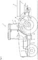
- Fig. 4 depicts an overall view of a tractor 1 as an exemplary a work vehicle.
- the work vehicle is not limited to a tractor, and may instead be a vehicle such as an agricultural vehicle, a combine or rice transplanter, or a construction vehicle.
- the tractor 1 includes a traveling vehicle body 3 having, among other things, wheels, a motor 4, and a transmission device 5.
- the motor 4 can be a diesel engine, gasoline engine, electric motor, or the like.
- the motor 4 is a diesel engine (hereafter referred to as "engine").
- the traveling vehicle body 3 includes a driver seat 6 as well as a cabin 7 encompassing or enclosing the driver seat 6.
- a coupler 8 can be utilizes such as a three-point hitch or hitching mechanism (or the like) and is located on a rear portion of the traveling vehicle body 3.
- a work apparatus 2 can be attached and detached from the coupler 8. By coupling the work apparatus 2 (for example, a tilling device, a fertilizer applicator, or a chemical spraying apparatus) to the coupler 8, the work apparatus 2 can be towed by the traveling vehicle body 3.
- the tractor 1 of Fig. 4 can be provided with the system of Fig. 1 .
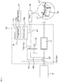
- This system includes an exhaust gas purification device 10.
- the exhaust gas purification device 10 is a device purifying exhaust gas emitted from an engine 4 and may be, for example, a nitrogen SCR device (nitrogen SCR system) that purifies NO x contained in the exhaust gas.
- the exhaust gas purification device 10 can perform a purification process purifying the exhaust gas.
- the exhaust gas purification device 10 can also perform an end process which collects aqueous urea after the purification process, or the like.
- the end process is a process that takes place after the engine has stopped running whereby the device 10 can collect unused purification fluid that remains in the system.
- the exhaust gas purification device 10 includes an SCR catalyst 11, a tank 12, a driver (or purification fluid delivery system) 13, and a control device 15.
- the SCR catalyst 11 functions to reduce NO x in the exhaust gas, and is arranged on or coupled to an exhaust channel or pipe 20 through which the exhaust gas of the engine 4 travels or flows.
- the SCR catalyst 11 causes the aqueous urea supplied to the exhaust channel 20 and the NO x in the exhaust gas to react.
- the resulting reaction substitutes or converts NO x into the harmless substances (H 2 O, N 2 ).
- the tank 12 is a tank used for storing the aqueous urea.
- the purification fluid delivery system 13 when driven by electricity or the like, delivers the fluid to purify the exhaust gas of NO x .
- the system 13 includes a pump 13a and a nozzle 13b.
- the pump 13a can be an electric pump connected to a battery 16 via power line(s) L1 and can thus be driven by electric power supplied from the batter 16 or the like.
- the pump 13a may be driven by either direct or alternating current. In the case of direct current, the pump 13a is driven by electric power from the power line(s) L1, which is connected to the battery 16. In the case of alternating current, the pump 13a can be driven by electric power output from a DC/AC converter (not shown in the drawings) coupled to the power line(s) L1 between the pump 13a and the battery 16.
- the pump 13a can be of the type that operates both in forward rotation or reverse rotation.
- forward rotation the aqueous urea in the tank 12 is sucked up from a suction intake and is discharged into a duct 21 that connects the pump 13a to the nozzle 13b.
- reverse rotation the pump 13a sucks in the aqueous urea in the duct 21 and returns the suctioned aqueous urea to the tank 12.
- the duct 21 can be a pipe, hose, or the like, and has a first end connected to the pump 13a and a second end connected to the nozzle 13b.
- the nozzle 13b is a device that can inject the aqueous urea received from the duct 21 into the exhaust channel 20.
- the nozzle 13b can, for example, include a solenoid valve, which can be energized by a control signal output from the control device 15.
- energizing the solenoid valve can causes a change in the injector, opening or closing of the injector as well as changes in the injector opening.
- the amount of aqueous urea injected into the exhaust channel 20 can change based on the control signal.
- the system 10 also utilizes a discharge channel or pipe 22.
- a first end of the discharge channel 22 is connected to the nozzle 13b and a second end of the discharge channel 22 is connected to an upper portion of the tank 12.
- a control device 15 is used to control the system 13 (pump 13a and nozzle 13b), and can have the form of a CPU or the like.
- the control device 15 is connected to the battery 16 via a power line(s) L1 and is supplied with electric power from the battery 16.
- the control device 15 can include a first controller 15a and a second controller 15b.
- the first controller 15a and the second controller 15b can be have the form of computer hardware and/or a program stored in the control device 15, or the like.
- the first control device can function as follows. In a case where the engine 4 is running, the first controller 15a executes control (purification control) to clean the exhaust gas by outputting a control signal to the system 13 (pump 13a and nozzle 13b).
- control purification control
- the operation of the engine 4 can be detected based on signals from one or more travel mechanisms 18 (such as, e.g., an ignition switch, one or more engine rotation sensors, injector sensors, and the like) which related to the operation of the engine 4.
- Each travel mechanism 18 can be connected to or otherwise communicate with the control device 15.
- the mechanism 18 can sense one or more of the following: a signal indicating that the ignition switch is on, a signal indicating the engine rotations detected by the engine rotation sensor, a signal indicating that the injector is operating, or the like. This is then input to the control device 15. In this way, the first controller 15a can determine that the engine 4 is running so that purification control can be activated or performed.
- the just-described way or ways of determining that the engine 4 is running is not limited to that described and can include others.
- a sensor such as gas detection sensor, gas flow amount sensor, or the like, can also be provided to the exhaust channel 20. This sensor can detect whether exhaust gas is flowing inside the exhaust channel 20. Then, in the case where the sensor detects that exhaust gas is flowing in the exhaust channel 20, the first controller 15a may perform the purification control.
- the exhaust sensor can be of the type described in US 9,441,514 to Tanaka issued on September 13, 2016 , the entire disclosure of which is herein expressly incorporated by reference in its entirety.
- the first controller 15a In the purification-control mode, the first controller 15a outputs a control signal to the pump 13a to perform normal rotation. This results in flow of urea from the tank 12 to the nozzle 13b. Also, as part of the purification control, the first controller 15a outputs a control signal to the solenoid of the nozzle 13b to open the nozzle 13b. This results in the injection of urea into the exhaust channel 20. Accordingly, when the first controller 15a performs the purification-control mode, the aqueous urea stored in the tank 12 is supplied to the nozzle 13b via the pump 13a, the aqueous urea supplied to the nozzle 13b is injected into the exhaust channel 20. The result is that the exhaust gas in the exhaust channel 20 can be cleaned by the injected aqueous urea.
- the second controller 15b can then execute an end-control mode (end process).
- the end-control mode (end process) refers to a control (a process) by which the system 13 collects the aqueous urea in the path where the aqueous urea travels (nozzle 13b and duct 21). This mode can also function to lower a temperature of the exhaust gas purification device 10 or the like.
- the second controller 15b can execute the end-control mode.
- the second controller 15b outputs a control signal to the pump 13a to perform reverse rotation.
- the result is that urea can flow from the nozzle 13b to the tank 12 via the line 21.
- the end mode can occur for a predetermined amount of time.
- a completion time of the end control can be stored ahead of time in a memory of the control device 15 or the like, and can be defined or set to be some tens of minutes, for example.
- the second controller 15b can thus measure the amount of time (elapsed time) the end-control mode is performed using an internal timer or the like. This way, in the case where the elapsed time measured by the internal timer reaches the completion time, the second controller 15b can end the end-control mode. In other words, the output of the control signal to the pump 13a can be stopped at this point.
- the completion time is not limited to the amount of time described above, and may be defined based on an amount of time sufficient to allow all or nearly all of the aqueous urea is collected, for example.
- the aqueous urea in the discharge channel 22 can thus be returned to the pump 13a via the nozzle 13b and the duct 21.
- the aqueous urea in the nozzle 13b, the duct 21, and the discharge channel 22 can be sucked in by the pump 13a and returned to the tank 12.
- the aqueous urea can be prevented from remaining in the system (the duct 21, the nozzle 13b, and the discharge channel 22).
- the aqueous urea can be prevented from remaining in the path where the aqueous urea travels during engine operation.
- the end-control mode at least the control device 15 and the pump 13a operate.
- the end process can ends partway through which can result in some aqueous urea remaining in the path where the aqueous urea travels (such as the nozzle 13b and duct 21).
- careless separation of the power line L1 from the battery 16 during execution of the end process can be prevented.
- the tractor 1 has a notification device 17.
- the notification device 17 is connected to the control device 15.
- the notification device 17 can be located in a vicinity of the battery 16 (for example, beside the battery 16, above the battery 16, near a terminal of the battery 16).
- the notification device 17 can be located in a vicinity of the driver seat 6 (for example, a metal panel provided in front of the driver seat 6).
- the notification device 17 can be configured as a speaker, LED, liquid crystal panel, or the like, and can provide an indication, warning, or notification via audio, visual (character display, light, or the like) so that one is made aware that the system 13 of the exhaust gas purification device 10 is performing the end process.
- the control device 15 can output to the notification device 17 a command that provides an external notification indicating that the end process is being performed (notification command).
- the notification device 17 Based on the notification command from the control device 15, the notification device 17 provides a notification that the end process is being performed, or that the suction intake by the pump 13a is being performed. This notification informs those who might disconnect the battery or otherwise perform a power interruption that the end-control mode is still operating and/or that they should wait until the end-control mode ends before doing so.
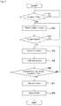
- Fig. 2 is an exemplary flow chart of operations of the exhaust gas purification device of the tractor 1 according to the present embodiment.
- the control device 15 first determines whether the engine 4 is running (S1). In a case where the engine 4 is running (S1: Yes), the first controller 15a operates the pump 13a and the nozzle 13b of the exhaust gas purification device 10 and executes the purification process (S2). Based on the signals from the traveling mechanism(s), the control device 15 determines whether the engine 4 has transitioned from the running state to the stopped state (S3). In a case where the engine 4 has not transitioned from the running status to the stopped status (S3: No), the first controller 15a continues the purification process.
- the second controller 15b operates the pump 13a of the exhaust gas purification device 10 and executes the end process (S4).
- the control device 15 outputs the notification command to the notification device 17, and the notification device 17 provides a notification (e.g., audio or visual) that the end process is being performed (S5).
- the second controller 15b determines whether the elapsed time of the end process has reached the completion time that was defined ahead of time (S6). In a case where the elapsed time of the end process has not reached the completion time (S6: No), the second controller 15b continues the end process and notification is continued.
- the second controller 15b stops the end process (S7).
- the control device 15 stops the output of the notification command to the notification device 17, and the notification device 17 stops providing the notification that the end process is being performed (S8).
- the notification device 17 provides external or exterior notification that the exhaust gas purification device 10 is performing the end process. Therefore, even in a state where the engine 4 has stopped running, an operator driving the tractor 1, a mechanic performing maintenance or the like on the tractor 1, or the like, can know that the exhaust gas purification device 10 is operating to perform the end process, and separation of the battery cord or the like from the battery 16 during the end process should not occur (and can be prevented).
- the notification device 17 provides the notification that the system 13 is performing the end process.
- the notification device 17 may instead provide notification that the end process in the system 13 is completed.
- the control device 15 outputs to the notification device 17 the notification command showing that the end process has completed (ended).
- the notification device 17 provides a notification to the exterior that the suction intake by the pump 13a is completed.
- the operator, mechanic, or the like can know a time at which the end process of the exhaust gas purification device 10 is completed. Accordingly, since the operator, mechanic, or the like, separates the battery cord or the like from the battery 16 after the end process is completed, careless separation of the battery cord from the battery 16 during the end process can be prevented.
- Fig. 3 depicts a modification of the exhaust gas purification device 10.
- the exhaust gas purification device 10 can include a circulation channel 23, an actuation valve 24, and a measurement device 25. As shown in Fig. 3 , a first end of the circulation channel 23 is arranged in a lower portion of the tank 12, and a second end of the circulation channel 23 is connected to the discharge channel 22.
- the actuation valve 24, which circulates the aqueous urea, is coupled to the circulation channel 23.
- the actuation valve 24 is one structural element included in the system 13, and can be configured as a magnetic valve capable of opening and closing.
- the actuation valve 24 opens and closes with a control signal output from the control device 15. In other words, the actuation valve 24 operates with the electric power of the battery 16.
- the measurement device 25 can be a device measuring a temperature of the aqueous urea, or measuring a temperature in an area around the exhaust gas purification device 10.
- the temperature of the aqueous urea or the temperature if the area around the exhaust gas purification device 10, measured by the measurement device 25, can be input to the control device 15.
- the first controller 15a demagnetizes the solenoid of the actuation valve 24 and closes the actuation valve 24. Also, the first controller 15a causes the pump 13a to perform forward rotation and opens the nozzle 13b. Thus results in the injection of urea into the exhaust system. Meanwhile, in the case of the end process mode, the second controller 15b of the control device 15 magnetizes the solenoid of the actuation valve 24 and opens the actuation valve 24. Also, in a state where the actuation valve 24 is open, the second controller 15b closes the nozzle 13b by demagnetizing the solenoid of the nozzle 13b and causes the pump 13a to perform forward rotation.
- the aqueous urea is circulated through the suction intake of the pump 13a, the duct 21, the nozzle 13b, the discharge channel 22, and also the circulation channel 23. Accordingly, the path where the aqueous urea travels, as well as the entire exhaust gas purification device 10, can be cooled.
- the second controller 15b can cause the pump 13a to perform reverse rotation in a state where the actuation valve 24 is open. Therefore, in the modification described above, in the end process, cooling can be performed by opening the actuation valve 24 to circulate the aqueous urea, and the aqueous urea can be collected by reverse rotation of the pump 13a.
- the notification device 17 can provide notification of the end process mode. Specifically, when the actuation valve 24 is open and the pump 13a is performing reverse rotation, the control device 15 outputs the notification command to the notification device 17. Based on the notification command from the control device 15, the notification device 17 provides a notification that the actuation valve 24 is open and the aqueous urea is being circulated, or that the suction intake of the aqueous urea by the pump 13a is being performed. Moreover, similar to the embodiment described above, the notification device 17 may also provide an external notification that the end process is completed.
Landscapes
- Engineering & Computer Science (AREA)
- Chemical & Material Sciences (AREA)
- Chemical Kinetics & Catalysis (AREA)
- Combustion & Propulsion (AREA)
- Mechanical Engineering (AREA)
- General Engineering & Computer Science (AREA)
- Health & Medical Sciences (AREA)
- Toxicology (AREA)
- Exhaust Gas After Treatment (AREA)
- Exhaust Gas Treatment By Means Of Catalyst (AREA)
Abstract
Description
- The present invention relates to an exhaust gas purification system and method for a work vehicle such as a tractor.
- Exhaust gas purification systems are conventional. A technology disclosed in
JP 2015-175265A - The exhaust gas purification device disclosed in
JP 2015-175265A - The work vehicle using the nitrogen SCR system typically has a battery mounted in the work vehicle. When performing maintenance, repair, or the like, on the work vehicle, one typically starts with a power supply interruption task which typically involves a disconnecting of the battery cord from the battery and/or activating (turning off) a breaker connecting the battery to various devices of the work vehicle. On the other hand, in vehicles with an exhaust gas purification device, after the engine stops running, an end process can be taking place which involves collecting the aqueous urea contained in pipes, for example. The end process, however, requires power and can be interrupted during power supply interruption. As such, when the end process is being performed by the exhaust gas purification device, in a case where there is a power supply interruption, the end process may be stopped partway through (not fully completed). This results in some aqueous urea remaining in the system pipes because it was not properly or fully collected.
- In view of the above circumstances, the present invention provides a work vehicle capable of preventing a power supply interruption task from being carelessly performed during an end process of an exhaust gas purification device. Non-limiting systems and methods are herein disclosed which can prevent or make less likely an interruption in the completion of the end process.
- <1> The above object is achieved by a work vehicle defined in the appended
claim 1. Further advantageous effects are obtained by preferred embodiments defined in the dependent of claims. A first aspect of the present invention provides a work vehicle comprising an engine; a battery; an exhaust gas purification system configured to operate in a purification-control mode and an end-control mode; and a notification device configured to output a notification indicating either one of (i) during the end-control mode; or (ii) an end of the end-control mode. - <2> According to a preferred embodiment of the work vehicle mentioned above, the exhaust gas purification system is configured to operate in said purification-control mode, when the engine is running, such that the exhaust gas purification system injects an exhaust gas purification fluid into an exhaust gas flow of the work vehicle.
- <3> According to another preferred embodiment of any one of the work vehicles mentioned above, an exhaust gas purification system is configured to operate in said end-control mode, after the engine has stopped running, such that the exhaust gas purification system collects the exhaust gas purification fluid in a path within the exhaust gas purification system.
- <4> According to another preferred embodiment of any one of the work vehicles mentioned above, the exhaust gas purification system is configured to determine whether the end-control mode is completed or is still activated based on:
- an operation status of a pump arranged in the exhaust gas purification system, and/or
- a period of time during which the operation in the end-control mode has been performed.
- Further preferably, the work vehicle has a lock mechanism which is configured to prevent the battery from being removed while the pump is working. For example, the notification device monitors the operational status of the pump to look/unlock the battery by the lock mechanism.
- <5> According to another preferred embodiment of any one of the work vehicles mentioned above, the exhaust gas purification system is configured to determine whether the end-control mode is completed or is still activated based on an open degree of a valve arranged within a circulation path of the exhaust-gas-purification fluid in the exhaust gas purification system.
- <6> According to another preferred embodiment of any one of the work vehicles mentioned above, the notification device is configured to output the notification in accordance with the determination of the exhaust gas purification system.
- <7> According to another preferred embodiment of any one of the work vehicles mentioned above, the notification device is configured to output the notification at least one of:
- during the operation in the end-control mode, and
- after the operation in the end-control mode.
- <8> According to another preferred embodiment of any one of the work vehicles mentioned above, the exhaust gas purification system has a pump, the pump being configured to be operated with electric power from the battery such that the exhaust gas purification system controls injection of an exhaust-gas-purification fluid into an exhaust gas channel of the work vehicle.
- <9> According to another preferred embodiment of any one of the work vehicles mentioned above, the exhaust gas purification system has a valve, the valve being configured to be operated with electric power from the battery such that the exhaust gas purification system controls circulation of the exhaust-gas-purification fluid therein.
- <10> According to another preferred embodiment of any one of the work vehicles mentioned above, the exhaust gas purification system has a tank configured to store exhaust-gas-purification fluid; a channel configured to circulate the exhaust-gas-purification fluid in the exhaust gas purification system; and a nozzle configured to inject the exhaust-gas-purification fluid into an exhaust flow of the work vehicle.
- <11> According to another preferred embodiment of any one of the work vehicles mentioned above, the notification device is adapted to output a visual indication.
It is preferable to output the visual indication on an operation board or console of the work vehicle on which a driver operates the vehicle. In addition or alternatively, the visual indication is preferably outputted on a display in the vicinity of the battery. Another example of the visual indication is a lamp configured to turn on for indicating the operation in the end-control mode. Another example of the visual indication is our flat panel display on which the operation status of the end-control mode is displayed. The above examples of visual indication may be used alone or in any combination thereof. - <12> According to another preferred embodiment of any one of the work vehicles mentioned above, the notification device is adapted to output an audible indication.
It is preferable to output the audible indication within a cabin where the driver controls the engine. In addition or alternatively, the audible indication is preferably outputted from a location in the vicinity of the battery. - <13> According to another preferred embodiment of any one of the work vehicles mentioned above, the notification device is arranged in a vicinity of the battery.
- <14> According to another preferred embodiment of any one of the work vehicles mentioned above, the notification device is arranged in a vicinity of a work vehicle driver seat.
- <15> A second aspect of the present invention provides a method for outputting a notification from a work vehicle comprising an engine, a battery, and an exhaust gas purification system that is configured to operate in a purification-control mode and an end-control mode, the method comprising determining whether the end-control mode is completed or is still activated; and outputting a notification via a notification device, wherein the notification is outputted at least one of during the operation in the end-control mode or after the operation in the end-control mode.
- The notification is preferably outputted during the operation in the end-control mode. In addition or alternatively, the other notification is preferably outputted after the completion of the operation in the end-control mode.
- A work vehicle according to another preferred embodiment of the present invention can include an engine, a battery, an exhaust gas purification device, and a notification device. The exhaust gas purification device is capable of performing a purification process purifying exhaust gas of the engine, and includes a driver (or purification fluid delivery system) which, after the purification process, operates with electric power from the battery and performs an end process. The notification device provides notification that the driver of the exhaust gas purification device is performing the end process.
- Also, a work vehicle according to another preferred embodiment of the present invention can include an engine, a battery, an exhaust gas purification device, and a notification device. The exhaust gas purification device is capable of performing a purification process purifying exhaust gas of the engine, and includes a driver which, after the purification process, operates with electric power from the battery and performs an end process. The notification device provides notification that the end process by the driver of the exhaust gas purification device is completed.
- The exhaust gas purification device can include a tank storing aqueous urea; a duct through which the aqueous urea passes; and a nozzle injecting the aqueous urea in the duct into an exhaust channel through which the exhaust gas of the engine passes. The driver includes a pump capable of discharging the aqueous urea within the tank during the purification process, the pump operating with electric power from the battery and performing suction intake of aqueous urea in the duct during the end process. During the suction intake by the pump, the notification device provides notification that the end process is being performed.
- The exhaust gas purification device can also include a tank storing aqueous urea; a duct through which the aqueous urea passes; and a nozzle injecting the aqueous urea in the duct into an exhaust channel through which the exhaust gas of the engine passes. The driver includes a pump capable of discharging the aqueous urea within the tank during the purification process, the pump operating with electric power from the battery and performing suction intake of the aqueous urea in the duct during the end process. When the suction intake by the pump is stopped, the notification device provides notification that the end process is completed.
- The exhaust gas purification device may also include a circulation channel capable of connecting to any of the tank, the duct, and the pump. The driver includes an actuation valve provided at an intermediate portion of the circulation channel, the actuation valve circulating the aqueous urea through the circulation channel by opening during the end process due to electric power from the battery. While the actuation valve is open, the notification device provides notification that the end process is being performed. The notification device is arranged in a vicinity of the battery.
- The work vehicle according to the present invention can prevent a power supply interruption task from being carelessly performed during an end process of an exhaust gas purification device.
- The present invention is further described in the detailed description which follows, in reference to the noted plurality of drawings by way of non-limiting examples of exemplary embodiments of the present invention, in which like reference numerals represent similar parts throughout the several views of the drawings, and wherein:
-
Fig. 1 is a schematic view of an exhaust gas purification device; -
Fig. 2 is a flow chart of operations of the exhaust gas purification device; -
Fig. 3 is a schematic view of a modification of an exhaust gas purification device; and -
Fig. 4 is an overall view of a work vehicle. - The particulars shown herein are by way of example and for purposes of illustrative discussion of the embodiments of the present invention only and are presented in the cause of providing what is believed to be the most useful and readily understood description of the principles and conceptual aspects of the present invention. In this regard, no attempt is made to show structural details of the present invention in more detail than is necessary for the fundamental understanding of the present invention, the description taken with the drawings making apparent to those skilled in the art how the forms of the present invention may be embodied in practice.
- Embodiments of the present invention are described below with reference to the drawings with
Figs. 1 and3 showing exemplary systems and withFig. 2 showing an exemplary method. -
Fig. 4 depicts an overall view of atractor 1 as an exemplary a work vehicle. The work vehicle is not limited to a tractor, and may instead be a vehicle such as an agricultural vehicle, a combine or rice transplanter, or a construction vehicle. - As shown in
Fig. 4 , thetractor 1 includes a travelingvehicle body 3 having, among other things, wheels, amotor 4, and atransmission device 5. Themotor 4 can be a diesel engine, gasoline engine, electric motor, or the like. In this embodiment, themotor 4 is a diesel engine (hereafter referred to as "engine"). - In addition, the traveling
vehicle body 3 includes a driver seat 6 as well as acabin 7 encompassing or enclosing the driver seat 6. Acoupler 8 can be utilizes such as a three-point hitch or hitching mechanism (or the like) and is located on a rear portion of the travelingvehicle body 3. A work apparatus 2 can be attached and detached from thecoupler 8. By coupling the work apparatus 2 (for example, a tilling device, a fertilizer applicator, or a chemical spraying apparatus) to thecoupler 8, the work apparatus 2 can be towed by the travelingvehicle body 3. - The
tractor 1 ofFig. 4 can be provided with the system ofFig. 1 . This system includes an exhaustgas purification device 10. The exhaustgas purification device 10 is a device purifying exhaust gas emitted from anengine 4 and may be, for example, a nitrogen SCR device (nitrogen SCR system) that purifies NOx contained in the exhaust gas. - Specifically, in the case where exhaust gas is emitted while the
engine 4 is running or is emitted from theengine 4, the exhaustgas purification device 10 can perform a purification process purifying the exhaust gas. The exhaustgas purification device 10 can also perform an end process which collects aqueous urea after the purification process, or the like. As noted above, the end process is a process that takes place after the engine has stopped running whereby thedevice 10 can collect unused purification fluid that remains in the system. - The exhaust
gas purification device 10 includes anSCR catalyst 11, atank 12, a driver (or purification fluid delivery system) 13, and acontrol device 15. - The
SCR catalyst 11 functions to reduce NOx in the exhaust gas, and is arranged on or coupled to an exhaust channel orpipe 20 through which the exhaust gas of theengine 4 travels or flows. TheSCR catalyst 11 causes the aqueous urea supplied to theexhaust channel 20 and the NOx in the exhaust gas to react. The resulting reaction substitutes or converts NOx into the harmless substances (H2O, N2). Thetank 12 is a tank used for storing the aqueous urea. - The purification
fluid delivery system 13, when driven by electricity or the like, delivers the fluid to purify the exhaust gas of NOx. Thesystem 13 includes apump 13a and anozzle 13b. Thepump 13a can be an electric pump connected to abattery 16 via power line(s) L1 and can thus be driven by electric power supplied from thebatter 16 or the like. Thepump 13a may be driven by either direct or alternating current. In the case of direct current, thepump 13a is driven by electric power from the power line(s) L1, which is connected to thebattery 16. In the case of alternating current, thepump 13a can be driven by electric power output from a DC/AC converter (not shown in the drawings) coupled to the power line(s) L1 between thepump 13a and thebattery 16. - The
pump 13a can be of the type that operates both in forward rotation or reverse rotation. During forward rotation, the aqueous urea in thetank 12 is sucked up from a suction intake and is discharged into aduct 21 that connects thepump 13a to thenozzle 13b. During reverse rotation, thepump 13a sucks in the aqueous urea in theduct 21 and returns the suctioned aqueous urea to thetank 12. Theduct 21 can be a pipe, hose, or the like, and has a first end connected to thepump 13a and a second end connected to thenozzle 13b. - The
nozzle 13b is a device that can inject the aqueous urea received from theduct 21 into theexhaust channel 20. Thenozzle 13b can, for example, include a solenoid valve, which can be energized by a control signal output from thecontrol device 15. Thus, for example, energizing the solenoid valve can causes a change in the injector, opening or closing of the injector as well as changes in the injector opening. In other words, the amount of aqueous urea injected into theexhaust channel 20 can change based on the control signal. - The
system 10 also utilizes a discharge channel orpipe 22. A first end of thedischarge channel 22 is connected to thenozzle 13b and a second end of thedischarge channel 22 is connected to an upper portion of thetank 12. With this arrangement, the aqueous urea not injected into theexhaust channel 20 can be discharged into thetank 12 via thedischarge channel 22. - A
control device 15 is used to control the system 13 (pump 13a andnozzle 13b), and can have the form of a CPU or the like. Thecontrol device 15 is connected to thebattery 16 via a power line(s) L1 and is supplied with electric power from thebattery 16. Thecontrol device 15 can include afirst controller 15a and asecond controller 15b. Thefirst controller 15a and thesecond controller 15b can be have the form of computer hardware and/or a program stored in thecontrol device 15, or the like. - The first control device can function as follows. In a case where the
engine 4 is running, thefirst controller 15a executes control (purification control) to clean the exhaust gas by outputting a control signal to the system 13 (pump 13a andnozzle 13b). The operation of theengine 4 can be detected based on signals from one or more travel mechanisms 18 (such as, e.g., an ignition switch, one or more engine rotation sensors, injector sensors, and the like) which related to the operation of theengine 4. Eachtravel mechanism 18 can be connected to or otherwise communicate with thecontrol device 15. For example, themechanism 18 can sense one or more of the following: a signal indicating that the ignition switch is on, a signal indicating the engine rotations detected by the engine rotation sensor, a signal indicating that the injector is operating, or the like. This is then input to thecontrol device 15. In this way, thefirst controller 15a can determine that theengine 4 is running so that purification control can be activated or performed. The just-described way or ways of determining that theengine 4 is running is not limited to that described and can include others. - A sensor (not shown) such as gas detection sensor, gas flow amount sensor, or the like, can also be provided to the
exhaust channel 20. This sensor can detect whether exhaust gas is flowing inside theexhaust channel 20. Then, in the case where the sensor detects that exhaust gas is flowing in theexhaust channel 20, thefirst controller 15a may perform the purification control. The exhaust sensor can be of the type described inUS 9,441,514 to Tanaka issued on September 13, 2016 - In the purification-control mode, the
first controller 15a outputs a control signal to thepump 13a to perform normal rotation. This results in flow of urea from thetank 12 to thenozzle 13b. Also, as part of the purification control, thefirst controller 15a outputs a control signal to the solenoid of thenozzle 13b to open thenozzle 13b. This results in the injection of urea into theexhaust channel 20. Accordingly, when thefirst controller 15a performs the purification-control mode, the aqueous urea stored in thetank 12 is supplied to thenozzle 13b via thepump 13a, the aqueous urea supplied to thenozzle 13b is injected into theexhaust channel 20. The result is that the exhaust gas in theexhaust channel 20 can be cleaned by the injected aqueous urea. - After the purification-control mode (purification process) ends, the
second controller 15b can then execute an end-control mode (end process). The end-control mode (end process) refers to a control (a process) by which thesystem 13 collects the aqueous urea in the path where the aqueous urea travels (nozzle 13b and duct 21). This mode can also function to lower a temperature of the exhaustgas purification device 10 or the like. - For example, in the case where the
engine 4 has transitioned from a running state to a stopped (not running) state, i.e., a state where flow of the exhaust gas has stopped, thesecond controller 15b can execute the end-control mode. In the end-control mode, thesecond controller 15b outputs a control signal to thepump 13a to perform reverse rotation. The result is that urea can flow from thenozzle 13b to thetank 12 via theline 21. The end mode can occur for a predetermined amount of time. For example, a completion time of the end control can be stored ahead of time in a memory of thecontrol device 15 or the like, and can be defined or set to be some tens of minutes, for example. Thesecond controller 15b can thus measure the amount of time (elapsed time) the end-control mode is performed using an internal timer or the like. This way, in the case where the elapsed time measured by the internal timer reaches the completion time, thesecond controller 15b can end the end-control mode. In other words, the output of the control signal to thepump 13a can be stopped at this point. The completion time is not limited to the amount of time described above, and may be defined based on an amount of time sufficient to allow all or nearly all of the aqueous urea is collected, for example. - When the
second controller 15b executes the end-control mode, the aqueous urea in thedischarge channel 22 can thus be returned to thepump 13a via thenozzle 13b and theduct 21. This means that the aqueous urea in thenozzle 13b can be returned to thepump 13a via theduct 21 and also that the aqueous urea in theduct 21 can return directly to thepump 13a. In this way, the aqueous urea in thenozzle 13b, theduct 21, and thedischarge channel 22 can be sucked in by thepump 13a and returned to thetank 12. Thus, the aqueous urea can be prevented from remaining in the system (theduct 21, thenozzle 13b, and the discharge channel 22). In other words, the aqueous urea can be prevented from remaining in the path where the aqueous urea travels during engine operation. - In the end-control mode (end process), at least the
control device 15 and thepump 13a operate. However, in the case where a terminal of the power line (battery cord, harness, or the like) L1 is separated from thebattery 16 while executing the end-control mode, the end process can ends partway through which can result in some aqueous urea remaining in the path where the aqueous urea travels (such as thenozzle 13b and duct 21). Thus, given the configuration (direction) illustrated in the following paragraphs, careless separation of the power line L1 from thebattery 16 during execution of the end process can be prevented. - To prevent careless separation or power interruption during the end-control mode, the
tractor 1 has anotification device 17. As shown inFig. 1 , thenotification device 17 is connected to thecontrol device 15. Thenotification device 17 can be located in a vicinity of the battery 16 (for example, beside thebattery 16, above thebattery 16, near a terminal of the battery 16). Alternatively, thenotification device 17 can be located in a vicinity of the driver seat 6 (for example, a metal panel provided in front of the driver seat 6). Thenotification device 17 can be configured as a speaker, LED, liquid crystal panel, or the like, and can provide an indication, warning, or notification via audio, visual (character display, light, or the like) so that one is made aware that thesystem 13 of the exhaustgas purification device 10 is performing the end process. For example, while thesecond controller 15b is outputting the control signal to thepump 13a (during suction intake of the aqueous urea by thepump 13a), thecontrol device 15 can output to the notification device 17 a command that provides an external notification indicating that the end process is being performed (notification command). Based on the notification command from thecontrol device 15, thenotification device 17 provides a notification that the end process is being performed, or that the suction intake by thepump 13a is being performed. This notification informs those who might disconnect the battery or otherwise perform a power interruption that the end-control mode is still operating and/or that they should wait until the end-control mode ends before doing so. -
Fig. 2 is an exemplary flow chart of operations of the exhaust gas purification device of thetractor 1 according to the present embodiment. - As shown in
Fig. 2 , based on the signals from the traveling mechanisms, thecontrol device 15 first determines whether theengine 4 is running (S1). In a case where theengine 4 is running (S1: Yes), thefirst controller 15a operates thepump 13a and thenozzle 13b of the exhaustgas purification device 10 and executes the purification process (S2). Based on the signals from the traveling mechanism(s), thecontrol device 15 determines whether theengine 4 has transitioned from the running state to the stopped state (S3). In a case where theengine 4 has not transitioned from the running status to the stopped status (S3: No), thefirst controller 15a continues the purification process. Meanwhile, in a case where theengine 4 has transitioned from the running status to the stopped status (S3: Yes), thesecond controller 15b operates thepump 13a of the exhaustgas purification device 10 and executes the end process (S4). In addition, thecontrol device 15 outputs the notification command to thenotification device 17, and thenotification device 17 provides a notification (e.g., audio or visual) that the end process is being performed (S5). Thesecond controller 15b determines whether the elapsed time of the end process has reached the completion time that was defined ahead of time (S6). In a case where the elapsed time of the end process has not reached the completion time (S6: No), thesecond controller 15b continues the end process and notification is continued. In a case where the elapsed time of the end process has reached the completion time (S6: Yes), thesecond controller 15b stops the end process (S7). In addition, thecontrol device 15 stops the output of the notification command to thenotification device 17, and thenotification device 17 stops providing the notification that the end process is being performed (S8). One now knows that power interruption can be performed and that doing so will not prevent completion of the end-control mode; because the end-control mode has already been completed. - As noted above, the
notification device 17 provides external or exterior notification that the exhaustgas purification device 10 is performing the end process. Therefore, even in a state where theengine 4 has stopped running, an operator driving thetractor 1, a mechanic performing maintenance or the like on thetractor 1, or the like, can know that the exhaustgas purification device 10 is operating to perform the end process, and separation of the battery cord or the like from thebattery 16 during the end process should not occur (and can be prevented). - In the embodiment described above, the
notification device 17 provides the notification that thesystem 13 is performing the end process. However, thenotification device 17 may instead provide notification that the end process in thesystem 13 is completed. For example, in the end-control mode, when thesecond controller 15b stops the output of the control signal to thepump 13a, thecontrol device 15 outputs to thenotification device 17 the notification command showing that the end process has completed (ended). Based on the notification command from thecontrol device 15, thenotification device 17 provides a notification to the exterior that the suction intake by thepump 13a is completed. In such a case, after theengine 4 has transitioned from the running state to the stopped state, the operator, mechanic, or the like, can know a time at which the end process of the exhaustgas purification device 10 is completed. Accordingly, since the operator, mechanic, or the like, separates the battery cord or the like from thebattery 16 after the end process is completed, careless separation of the battery cord from thebattery 16 during the end process can be prevented. -
Fig. 3 depicts a modification of the exhaustgas purification device 10. The exhaustgas purification device 10 can include acirculation channel 23, anactuation valve 24, and ameasurement device 25. As shown inFig. 3 , a first end of thecirculation channel 23 is arranged in a lower portion of thetank 12, and a second end of thecirculation channel 23 is connected to thedischarge channel 22. Theactuation valve 24, which circulates the aqueous urea, is coupled to thecirculation channel 23. Theactuation valve 24 is one structural element included in thesystem 13, and can be configured as a magnetic valve capable of opening and closing. Theactuation valve 24 opens and closes with a control signal output from thecontrol device 15. In other words, theactuation valve 24 operates with the electric power of thebattery 16. Themeasurement device 25 can be a device measuring a temperature of the aqueous urea, or measuring a temperature in an area around the exhaustgas purification device 10. The temperature of the aqueous urea or the temperature if the area around the exhaustgas purification device 10, measured by themeasurement device 25, can be input to thecontrol device 15. - In the case of the purification process mode, the
first controller 15a demagnetizes the solenoid of theactuation valve 24 and closes theactuation valve 24. Also, thefirst controller 15a causes thepump 13a to perform forward rotation and opens thenozzle 13b. Thus results in the injection of urea into the exhaust system. Meanwhile, in the case of the end process mode, thesecond controller 15b of thecontrol device 15 magnetizes the solenoid of theactuation valve 24 and opens theactuation valve 24. Also, in a state where theactuation valve 24 is open, thesecond controller 15b closes thenozzle 13b by demagnetizing the solenoid of thenozzle 13b and causes thepump 13a to perform forward rotation. Therefore, in the end process mode, the aqueous urea is circulated through the suction intake of thepump 13a, theduct 21, thenozzle 13b, thedischarge channel 22, and also thecirculation channel 23. Accordingly, the path where the aqueous urea travels, as well as the entire exhaustgas purification device 10, can be cooled. - Also, in the end process, under conditions where the aqueous urea is being circulated, when the temperature of the aqueous urea or the temperature in the area around the exhaust
gas purification device 10, measured by themeasurement device 25, is equal to or less than a predetermined temperature, thesecond controller 15b can cause thepump 13a to perform reverse rotation in a state where theactuation valve 24 is open. Therefore, in the modification described above, in the end process, cooling can be performed by opening theactuation valve 24 to circulate the aqueous urea, and the aqueous urea can be collected by reverse rotation of thepump 13a. - In the case of the modification shown in
Fig. 3 , also, thenotification device 17 can provide notification of the end process mode. Specifically, when theactuation valve 24 is open and thepump 13a is performing reverse rotation, thecontrol device 15 outputs the notification command to thenotification device 17. Based on the notification command from thecontrol device 15, thenotification device 17 provides a notification that theactuation valve 24 is open and the aqueous urea is being circulated, or that the suction intake of the aqueous urea by thepump 13a is being performed. Moreover, similar to the embodiment described above, thenotification device 17 may also provide an external notification that the end process is completed. - The embodiments disclosed herein are in all respects exemplary and should not be considered limiting. The scope of the present invention is indicated not by the preceding description but rather by the scope of the patent claims, and all modifications within the scope of the patent claims are included.
- It is noted that the foregoing examples have been provided merely for the purpose of explanation and are in no way to be construed as limiting of the present invention. While the present invention has been described with reference to exemplary embodiments, it is understood that the words which have been used herein are words of description and illustration, rather than words of limitation. Changes may be made, within the purview of the appended claims, as presently stated and as amended, without departing from the scope and spirit of the present invention in its aspects. Although the present invention has been described herein with reference to particular structures, materials and embodiments, the present invention is not intended to be limited to the particulars disclosed herein; rather, the present invention extends to all structures, methods and uses within the scope of the appended claims.
- The present invention is not limited to the above described embodiments, and various variations and modifications may be possible without departing from the scope of the present invention.
Claims (15)
- A work vehicle (1) comprising:an engine (4);a battery (16);an exhaust gas purification system (10) configured to operate in a purification-control mode and an end-control mode; anda notification device (17) configured to output a notification indicating either one of:during the end-control mode; oran end of the end-control mode.
- The work vehicle (1) according to claim 1, wherein
the exhaust gas purification system (10) is configured to operate in said purification-control mode, when the engine (4) is running, such that the exhaust gas purification system (10) injects an exhaust gas purification fluid into an exhaust gas flow of the work vehicle. - The work vehicle (1) according to claim 1 or 2, wherein
an exhaust gas purification system (10) is configured to operate in said end-control mode, after the engine (4) has stopped running, such that the exhaust gas purification system (10) collects the exhaust gas purification fluid in a path within the exhaust gas purification system (10). - The work vehicle (1) according to any one of claims 1 to 3, wherein
the exhaust gas purification system (10) is configured to determine whether the end-control mode is completed or is still activated based on:an operation status of a pump arranged in the exhaust gas purification system (10), and/ora period of time during which the operation in the end-control mode has been performed. - The work vehicle (1) according to any one of claims 1 to 4, wherein
the exhaust gas purification system (10) is configured to determine whether the end-control mode is completed or is still activated based on an open degree of a valve arranged within a circulation path of the exhaust-gas-purification fluid in the exhaust gas purification system (10). - The work vehicle (1) according to any one of claims 1 to 5, wherein
the notification device (17) is configured to output the notification in accordance with the determination of the exhaust gas purification system (10). - The work vehicle (1) according to any one of claims 1 to 6, wherein
the notification device (17) is configured to output the notification at least one of:during the operation in the end-control mode, andafter the operation in the end-control mode. - The work vehicle (1) according to any one of claims 1 to 7, wherein
the exhaust gas purification system (10) has a pump, the pump being configured to be operated with electric power from the battery (16) such that the exhaust gas purification system (10) controls injection of an exhaust-gas-purification fluid into an exhaust gas channel of the work vehicle. - The work vehicle (1) according to any one of claims 1 to 8, wherein
the exhaust gas purification system (10) has a valve, the valve being configured to be operated with electric power from the battery (16) such that the exhaust gas purification system (10) controls circulation of the exhaust-gas-purification fluid therein. - The work vehicle (1) according to any one claims 1 to 9, wherein the exhaust gas purification system (10) has:a tank configured to store exhaust-gas-purification fluid;a channel configured to circulate the exhaust-gas-purification fluid in the exhaust gas purification system (10); anda nozzle configured to inject the exhaust-gas-purification fluid into an exhaust flow of the work vehicle.
- The work vehicle (1) according to any one of claims 1 to 10, wherein the notification device (17) is adapted to output a visual indication.
- The work vehicle (1) according to any one of claims 1 to 11, wherein the notification device (17) is adapted to output an audible indication.
- The work vehicle (1) according to any one of claims 1 to 12, wherein the notification device (17) is arranged in a vicinity of the battery (16).
- The work vehicle (1) according to any one of claims 1 to 13, wherein the notification device (17) is arranged in a vicinity of a work vehicle driver seat.
- A method for outputting a notification from a work vehicle comprising an engine (4), a battery (16), and an exhaust gas purification system (10) that is configured to operate in a purification-control mode and an end-control mode, the method comprising:determining whether the end-control mode is completed or is still activated; andoutputting a notification via a notification device (17),wherein the notification is outputted at least one of:during the operation in the end-control mode; orafter the operation in the end-control mode.
Applications Claiming Priority (1)
| Application Number | Priority Date | Filing Date | Title |
|---|---|---|---|
| JP2016106395A JP6612178B2 (en) | 2016-05-27 | 2016-05-27 | Working machine |
Publications (2)
| Publication Number | Publication Date |
|---|---|
| EP3249191A1 true EP3249191A1 (en) | 2017-11-29 |
| EP3249191B1 EP3249191B1 (en) | 2018-12-26 |
Family
ID=58772796
Family Applications (1)
| Application Number | Title | Priority Date | Filing Date |
|---|---|---|---|
| EP17172885.0A Active EP3249191B1 (en) | 2016-05-27 | 2017-05-24 | Exhaust gas purification system and method for a work vehicle |
Country Status (3)
| Country | Link |
|---|---|
| US (1) | US10184378B2 (en) |
| EP (1) | EP3249191B1 (en) |
| JP (1) | JP6612178B2 (en) |
Families Citing this family (1)
| Publication number | Priority date | Publication date | Assignee | Title |
|---|---|---|---|---|
| CN114215629B (en) * | 2021-12-02 | 2023-01-31 | 江铃汽车股份有限公司 | Emptying method of electronic control type urea injection system |
Citations (6)
| Publication number | Priority date | Publication date | Assignee | Title |
|---|---|---|---|---|
| US20120036838A1 (en) * | 2009-04-13 | 2012-02-16 | Bosch Corporation | Exhaust purification system for a vehicle |
| US20130032214A1 (en) * | 2010-04-13 | 2013-02-07 | Peugeot Citroen Automobiles Sa | Purge phase control strategy for a selected catalytic reduction system |
| EP2682581A1 (en) * | 2012-07-03 | 2014-01-08 | Toyota Jidosha Kabushiki Kaisha | Exhaust emission control apparatus for internal combustion engine, and control method for the exhaust emission control apparatus |
| US20150239410A1 (en) * | 2014-02-24 | 2015-08-27 | Perkins Engines Company Limited | Electrical Bypass Circuit |
| JP2015175265A (en) | 2014-03-14 | 2015-10-05 | 株式会社クボタ | Engine urea SCR system |
| US9441514B2 (en) | 2013-12-26 | 2016-09-13 | Kubota Corporation | Diesel engine |
-
2016
- 2016-05-27 JP JP2016106395A patent/JP6612178B2/en active Active
-
2017
- 2017-05-11 US US15/592,552 patent/US10184378B2/en active Active
- 2017-05-24 EP EP17172885.0A patent/EP3249191B1/en active Active
Patent Citations (6)
| Publication number | Priority date | Publication date | Assignee | Title |
|---|---|---|---|---|
| US20120036838A1 (en) * | 2009-04-13 | 2012-02-16 | Bosch Corporation | Exhaust purification system for a vehicle |
| US20130032214A1 (en) * | 2010-04-13 | 2013-02-07 | Peugeot Citroen Automobiles Sa | Purge phase control strategy for a selected catalytic reduction system |
| EP2682581A1 (en) * | 2012-07-03 | 2014-01-08 | Toyota Jidosha Kabushiki Kaisha | Exhaust emission control apparatus for internal combustion engine, and control method for the exhaust emission control apparatus |
| US9441514B2 (en) | 2013-12-26 | 2016-09-13 | Kubota Corporation | Diesel engine |
| US20150239410A1 (en) * | 2014-02-24 | 2015-08-27 | Perkins Engines Company Limited | Electrical Bypass Circuit |
| JP2015175265A (en) | 2014-03-14 | 2015-10-05 | 株式会社クボタ | Engine urea SCR system |
Also Published As
| Publication number | Publication date |
|---|---|
| US10184378B2 (en) | 2019-01-22 |
| US20170342885A1 (en) | 2017-11-30 |
| EP3249191B1 (en) | 2018-12-26 |
| JP6612178B2 (en) | 2019-11-27 |
| JP2017210947A (en) | 2017-11-30 |
Similar Documents
| Publication | Publication Date | Title |
|---|---|---|
| KR101630588B1 (en) | Work vehicle | |
| JP5789925B2 (en) | NOx sensor diagnostic device and SCR system | |
| US9534551B2 (en) | Working machine | |
| KR101665278B1 (en) | Work vehicle | |
| CN102892985B (en) | Scr system | |
| US9758946B2 (en) | Work vehicle | |
| US20120036838A1 (en) | Exhaust purification system for a vehicle | |
| US9404464B2 (en) | Controlled engine shutdown method and engine shutdown prediction for exhaust system durability | |
| US20070199308A1 (en) | Exhaust emission purifying apparatus for engine | |
| US20130055700A1 (en) | Selective catalytic reduction system | |
| CN110273798A (en) | System and method for fuel filter diagnosis | |
| WO2011148811A1 (en) | Selective catalytic reduction system | |
| CN102197201A (en) | System and method for heating a reducing agent associated with a reducing agent distribution system | |
| EP2573343B1 (en) | Competency diagnosis system for urea water temperature sensor | |
| JP2011179360A (en) | Urea quality diagnosis system | |
| US10865680B2 (en) | Exhaust gas purifying device of work machine | |
| EP3249191B1 (en) | Exhaust gas purification system and method for a work vehicle | |
| JP6905910B2 (en) | Diagnostic device and diagnostic method | |
| US10914210B2 (en) | Engine unit | |
| JP2017218937A (en) | Urea injection control device | |
| JP5617342B2 (en) | SCR system | |
| JP2019035343A (en) | Electronic control unit for exhaust purification system | |
| JP2018119413A (en) | Electronic control device of exhaust emission control system | |
| JP2021017809A (en) | Reducing agent supply device, control method for the same and exhaust emission control device |
Legal Events
| Date | Code | Title | Description |
|---|---|---|---|
| PUAI | Public reference made under article 153(3) epc to a published international application that has entered the european phase |
Free format text: ORIGINAL CODE: 0009012 |
|
| STAA | Information on the status of an ep patent application or granted ep patent |
Free format text: STATUS: THE APPLICATION HAS BEEN PUBLISHED |
|
| AK | Designated contracting states |
Kind code of ref document: A1 Designated state(s): AL AT BE BG CH CY CZ DE DK EE ES FI FR GB GR HR HU IE IS IT LI LT LU LV MC MK MT NL NO PL PT RO RS SE SI SK SM TR |
|
| AX | Request for extension of the european patent |
Extension state: BA ME |
|
| STAA | Information on the status of an ep patent application or granted ep patent |
Free format text: STATUS: REQUEST FOR EXAMINATION WAS MADE |
|
| 17P | Request for examination filed |
Effective date: 20180116 |
|
| RBV | Designated contracting states (corrected) |
Designated state(s): AL AT BE BG CH CY CZ DE DK EE ES FI FR GB GR HR HU IE IS IT LI LT LU LV MC MK MT NL NO PL PT RO RS SE SI SK SM TR |
|
| STAA | Information on the status of an ep patent application or granted ep patent |
Free format text: STATUS: EXAMINATION IS IN PROGRESS |
|
| 17Q | First examination report despatched |
Effective date: 20180419 |
|
| GRAP | Despatch of communication of intention to grant a patent |
Free format text: ORIGINAL CODE: EPIDOSNIGR1 |
|
| STAA | Information on the status of an ep patent application or granted ep patent |
Free format text: STATUS: GRANT OF PATENT IS INTENDED |
|
| INTG | Intention to grant announced |
Effective date: 20181001 |
|
| GRAS | Grant fee paid |
Free format text: ORIGINAL CODE: EPIDOSNIGR3 |
|
| GRAJ | Information related to disapproval of communication of intention to grant by the applicant or resumption of examination proceedings by the epo deleted |
Free format text: ORIGINAL CODE: EPIDOSDIGR1 |
|
| GRAL | Information related to payment of fee for publishing/printing deleted |
Free format text: ORIGINAL CODE: EPIDOSDIGR3 |
|
| STAA | Information on the status of an ep patent application or granted ep patent |
Free format text: STATUS: EXAMINATION IS IN PROGRESS |
|
| GRAR | Information related to intention to grant a patent recorded |
Free format text: ORIGINAL CODE: EPIDOSNIGR71 |
|
| STAA | Information on the status of an ep patent application or granted ep patent |
Free format text: STATUS: GRANT OF PATENT IS INTENDED |
|
| GRAA | (expected) grant |
Free format text: ORIGINAL CODE: 0009210 |
|
| STAA | Information on the status of an ep patent application or granted ep patent |
Free format text: STATUS: THE PATENT HAS BEEN GRANTED |
|
| INTC | Intention to grant announced (deleted) | ||
| AK | Designated contracting states |
Kind code of ref document: B1 Designated state(s): AL AT BE BG CH CY CZ DE DK EE ES FI FR GB GR HR HU IE IS IT LI LT LU LV MC MK MT NL NO PL PT RO RS SE SI SK SM TR |
|
| INTG | Intention to grant announced |
Effective date: 20181121 |
|
| REG | Reference to a national code |
Ref country code: GB Ref legal event code: FG4D |
|
| REG | Reference to a national code |
Ref country code: CH Ref legal event code: EP |
|
| REG | Reference to a national code |
Ref country code: AT Ref legal event code: REF Ref document number: 1081725 Country of ref document: AT Kind code of ref document: T Effective date: 20190115 |
|
| REG | Reference to a national code |
Ref country code: DE Ref legal event code: R096 Ref document number: 602017001556 Country of ref document: DE |
|
| REG | Reference to a national code |
Ref country code: IE Ref legal event code: FG4D |
|
| PG25 | Lapsed in a contracting state [announced via postgrant information from national office to epo] |
Ref country code: LV Free format text: LAPSE BECAUSE OF FAILURE TO SUBMIT A TRANSLATION OF THE DESCRIPTION OR TO PAY THE FEE WITHIN THE PRESCRIBED TIME-LIMIT Effective date: 20181226 Ref country code: LT Free format text: LAPSE BECAUSE OF FAILURE TO SUBMIT A TRANSLATION OF THE DESCRIPTION OR TO PAY THE FEE WITHIN THE PRESCRIBED TIME-LIMIT Effective date: 20181226 Ref country code: BG Free format text: LAPSE BECAUSE OF FAILURE TO SUBMIT A TRANSLATION OF THE DESCRIPTION OR TO PAY THE FEE WITHIN THE PRESCRIBED TIME-LIMIT Effective date: 20190326 Ref country code: HR Free format text: LAPSE BECAUSE OF FAILURE TO SUBMIT A TRANSLATION OF THE DESCRIPTION OR TO PAY THE FEE WITHIN THE PRESCRIBED TIME-LIMIT Effective date: 20181226 Ref country code: FI Free format text: LAPSE BECAUSE OF FAILURE TO SUBMIT A TRANSLATION OF THE DESCRIPTION OR TO PAY THE FEE WITHIN THE PRESCRIBED TIME-LIMIT Effective date: 20181226 Ref country code: NO Free format text: LAPSE BECAUSE OF FAILURE TO SUBMIT A TRANSLATION OF THE DESCRIPTION OR TO PAY THE FEE WITHIN THE PRESCRIBED TIME-LIMIT Effective date: 20190326 |
|
| REG | Reference to a national code |
Ref country code: NL Ref legal event code: MP Effective date: 20181226 |
|
| REG | Reference to a national code |
Ref country code: LT Ref legal event code: MG4D |
|
| PG25 | Lapsed in a contracting state [announced via postgrant information from national office to epo] |
Ref country code: GR Free format text: LAPSE BECAUSE OF FAILURE TO SUBMIT A TRANSLATION OF THE DESCRIPTION OR TO PAY THE FEE WITHIN THE PRESCRIBED TIME-LIMIT Effective date: 20190327 Ref country code: RS Free format text: LAPSE BECAUSE OF FAILURE TO SUBMIT A TRANSLATION OF THE DESCRIPTION OR TO PAY THE FEE WITHIN THE PRESCRIBED TIME-LIMIT Effective date: 20181226 Ref country code: AL Free format text: LAPSE BECAUSE OF FAILURE TO SUBMIT A TRANSLATION OF THE DESCRIPTION OR TO PAY THE FEE WITHIN THE PRESCRIBED TIME-LIMIT Effective date: 20181226 Ref country code: SE Free format text: LAPSE BECAUSE OF FAILURE TO SUBMIT A TRANSLATION OF THE DESCRIPTION OR TO PAY THE FEE WITHIN THE PRESCRIBED TIME-LIMIT Effective date: 20181226 |
|
| REG | Reference to a national code |
Ref country code: AT Ref legal event code: MK05 Ref document number: 1081725 Country of ref document: AT Kind code of ref document: T Effective date: 20181226 |
|
| PG25 | Lapsed in a contracting state [announced via postgrant information from national office to epo] |
Ref country code: NL Free format text: LAPSE BECAUSE OF FAILURE TO SUBMIT A TRANSLATION OF THE DESCRIPTION OR TO PAY THE FEE WITHIN THE PRESCRIBED TIME-LIMIT Effective date: 20181226 |
|
| PG25 | Lapsed in a contracting state [announced via postgrant information from national office to epo] |
Ref country code: ES Free format text: LAPSE BECAUSE OF FAILURE TO SUBMIT A TRANSLATION OF THE DESCRIPTION OR TO PAY THE FEE WITHIN THE PRESCRIBED TIME-LIMIT Effective date: 20181226 Ref country code: PT Free format text: LAPSE BECAUSE OF FAILURE TO SUBMIT A TRANSLATION OF THE DESCRIPTION OR TO PAY THE FEE WITHIN THE PRESCRIBED TIME-LIMIT Effective date: 20190426 Ref country code: IT Free format text: LAPSE BECAUSE OF FAILURE TO SUBMIT A TRANSLATION OF THE DESCRIPTION OR TO PAY THE FEE WITHIN THE PRESCRIBED TIME-LIMIT Effective date: 20181226 Ref country code: CZ Free format text: LAPSE BECAUSE OF FAILURE TO SUBMIT A TRANSLATION OF THE DESCRIPTION OR TO PAY THE FEE WITHIN THE PRESCRIBED TIME-LIMIT Effective date: 20181226 Ref country code: PL Free format text: LAPSE BECAUSE OF FAILURE TO SUBMIT A TRANSLATION OF THE DESCRIPTION OR TO PAY THE FEE WITHIN THE PRESCRIBED TIME-LIMIT Effective date: 20181226 |
|
| PG25 | Lapsed in a contracting state [announced via postgrant information from national office to epo] |
Ref country code: RO Free format text: LAPSE BECAUSE OF FAILURE TO SUBMIT A TRANSLATION OF THE DESCRIPTION OR TO PAY THE FEE WITHIN THE PRESCRIBED TIME-LIMIT Effective date: 20181226 Ref country code: SK Free format text: LAPSE BECAUSE OF FAILURE TO SUBMIT A TRANSLATION OF THE DESCRIPTION OR TO PAY THE FEE WITHIN THE PRESCRIBED TIME-LIMIT Effective date: 20181226 Ref country code: SM Free format text: LAPSE BECAUSE OF FAILURE TO SUBMIT A TRANSLATION OF THE DESCRIPTION OR TO PAY THE FEE WITHIN THE PRESCRIBED TIME-LIMIT Effective date: 20181226 Ref country code: EE Free format text: LAPSE BECAUSE OF FAILURE TO SUBMIT A TRANSLATION OF THE DESCRIPTION OR TO PAY THE FEE WITHIN THE PRESCRIBED TIME-LIMIT Effective date: 20181226 Ref country code: IS Free format text: LAPSE BECAUSE OF FAILURE TO SUBMIT A TRANSLATION OF THE DESCRIPTION OR TO PAY THE FEE WITHIN THE PRESCRIBED TIME-LIMIT Effective date: 20190426 |
|
| REG | Reference to a national code |
Ref country code: DE Ref legal event code: R097 Ref document number: 602017001556 Country of ref document: DE |
|
| PG25 | Lapsed in a contracting state [announced via postgrant information from national office to epo] |
Ref country code: AT Free format text: LAPSE BECAUSE OF FAILURE TO SUBMIT A TRANSLATION OF THE DESCRIPTION OR TO PAY THE FEE WITHIN THE PRESCRIBED TIME-LIMIT Effective date: 20181226 Ref country code: DK Free format text: LAPSE BECAUSE OF FAILURE TO SUBMIT A TRANSLATION OF THE DESCRIPTION OR TO PAY THE FEE WITHIN THE PRESCRIBED TIME-LIMIT Effective date: 20181226 |
|
| PLBE | No opposition filed within time limit |
Free format text: ORIGINAL CODE: 0009261 |
|
| STAA | Information on the status of an ep patent application or granted ep patent |
Free format text: STATUS: NO OPPOSITION FILED WITHIN TIME LIMIT |
|
| REG | Reference to a national code |
Ref country code: DE Ref legal event code: R119 Ref document number: 602017001556 Country of ref document: DE |
|
| 26N | No opposition filed |
Effective date: 20190927 |
|
| PG25 | Lapsed in a contracting state [announced via postgrant information from national office to epo] |
Ref country code: MC Free format text: LAPSE BECAUSE OF FAILURE TO SUBMIT A TRANSLATION OF THE DESCRIPTION OR TO PAY THE FEE WITHIN THE PRESCRIBED TIME-LIMIT Effective date: 20181226 |
|
| REG | Reference to a national code |
Ref country code: BE Ref legal event code: MM Effective date: 20190531 |
|
| PG25 | Lapsed in a contracting state [announced via postgrant information from national office to epo] |
Ref country code: SI Free format text: LAPSE BECAUSE OF FAILURE TO SUBMIT A TRANSLATION OF THE DESCRIPTION OR TO PAY THE FEE WITHIN THE PRESCRIBED TIME-LIMIT Effective date: 20181226 Ref country code: LU Free format text: LAPSE BECAUSE OF NON-PAYMENT OF DUE FEES Effective date: 20190524 |
|
| PG25 | Lapsed in a contracting state [announced via postgrant information from national office to epo] |
Ref country code: TR Free format text: LAPSE BECAUSE OF FAILURE TO SUBMIT A TRANSLATION OF THE DESCRIPTION OR TO PAY THE FEE WITHIN THE PRESCRIBED TIME-LIMIT Effective date: 20181226 |
|
| PG25 | Lapsed in a contracting state [announced via postgrant information from national office to epo] |
Ref country code: DE Free format text: LAPSE BECAUSE OF NON-PAYMENT OF DUE FEES Effective date: 20191203 Ref country code: IE Free format text: LAPSE BECAUSE OF NON-PAYMENT OF DUE FEES Effective date: 20190524 |
|
| PG25 | Lapsed in a contracting state [announced via postgrant information from national office to epo] |
Ref country code: BE Free format text: LAPSE BECAUSE OF NON-PAYMENT OF DUE FEES Effective date: 20190531 |
|
| PG25 | Lapsed in a contracting state [announced via postgrant information from national office to epo] |
Ref country code: LI Free format text: LAPSE BECAUSE OF NON-PAYMENT OF DUE FEES Effective date: 20200531 Ref country code: CH Free format text: LAPSE BECAUSE OF NON-PAYMENT OF DUE FEES Effective date: 20200531 |
|
| PG25 | Lapsed in a contracting state [announced via postgrant information from national office to epo] |
Ref country code: CY Free format text: LAPSE BECAUSE OF FAILURE TO SUBMIT A TRANSLATION OF THE DESCRIPTION OR TO PAY THE FEE WITHIN THE PRESCRIBED TIME-LIMIT Effective date: 20181226 |
|
| PG25 | Lapsed in a contracting state [announced via postgrant information from national office to epo] |
Ref country code: MT Free format text: LAPSE BECAUSE OF FAILURE TO SUBMIT A TRANSLATION OF THE DESCRIPTION OR TO PAY THE FEE WITHIN THE PRESCRIBED TIME-LIMIT Effective date: 20181226 Ref country code: HU Free format text: LAPSE BECAUSE OF FAILURE TO SUBMIT A TRANSLATION OF THE DESCRIPTION OR TO PAY THE FEE WITHIN THE PRESCRIBED TIME-LIMIT; INVALID AB INITIO Effective date: 20170524 |
|
| GBPC | Gb: european patent ceased through non-payment of renewal fee |
Effective date: 20210524 |
|
| PG25 | Lapsed in a contracting state [announced via postgrant information from national office to epo] |
Ref country code: GB Free format text: LAPSE BECAUSE OF NON-PAYMENT OF DUE FEES Effective date: 20210524 |
|
| PG25 | Lapsed in a contracting state [announced via postgrant information from national office to epo] |
Ref country code: MK Free format text: LAPSE BECAUSE OF FAILURE TO SUBMIT A TRANSLATION OF THE DESCRIPTION OR TO PAY THE FEE WITHIN THE PRESCRIBED TIME-LIMIT Effective date: 20181226 |
|
| REG | Reference to a national code |
Ref country code: FR Ref legal event code: PLFP Year of fee payment: 7 |
|
| PGFP | Annual fee paid to national office [announced via postgrant information from national office to epo] |
Ref country code: FR Payment date: 20250401 Year of fee payment: 9 |