EP3249140A1 - Lock and assembly - Google Patents
Lock and assembly Download PDFInfo
- Publication number
- EP3249140A1 EP3249140A1 EP17172887.6A EP17172887A EP3249140A1 EP 3249140 A1 EP3249140 A1 EP 3249140A1 EP 17172887 A EP17172887 A EP 17172887A EP 3249140 A1 EP3249140 A1 EP 3249140A1
- Authority
- EP
- European Patent Office
- Prior art keywords
- lock
- pin
- male portion
- leaf
- female portion
- Prior art date
- Legal status (The legal status is an assumption and is not a legal conclusion. Google has not performed a legal analysis and makes no representation as to the accuracy of the status listed.)
- Granted
Links
Images




Classifications
-
- E—FIXED CONSTRUCTIONS
- E05—LOCKS; KEYS; WINDOW OR DOOR FITTINGS; SAFES
- E05B—LOCKS; ACCESSORIES THEREFOR; HANDCUFFS
- E05B15/00—Other details of locks; Parts for engagement by bolts of fastening devices
- E05B15/0033—Spindles for handles, e.g. square spindles
-
- E—FIXED CONSTRUCTIONS
- E05—LOCKS; KEYS; WINDOW OR DOOR FITTINGS; SAFES
- E05B—LOCKS; ACCESSORIES THEREFOR; HANDCUFFS
- E05B3/00—Fastening knobs or handles to lock or latch parts
- E05B3/04—Fastening the knob or the handle shank to the spindle by screws, springs or snap bolts
-
- E—FIXED CONSTRUCTIONS
- E05—LOCKS; KEYS; WINDOW OR DOOR FITTINGS; SAFES
- E05B—LOCKS; ACCESSORIES THEREFOR; HANDCUFFS
- E05B63/00—Locks or fastenings with special structural characteristics
- E05B63/0056—Locks with adjustable or exchangeable lock parts
- E05B63/006—Locks with adjustable or exchangeable lock parts for different door thicknesses
Definitions
- the present invention relates to a lock, a square pin and an assembly comprising the aforementioned lock or the aforementioned pin associated with a leaf of a door, a window, or the like.
- the present invention is set forth in the foregoing context, aiming to provide a more adaptable lock for a plurality of different door thicknesses, and to ensure this adaptability by means of a special square pin which, with the same mechanical strength, may be adjusted in length.
- the reference numerals 1, 1', 1" distinguish, in its entirety, a lock to secure a door or window leaf 20 to a jamb.
- such door or window leaf is of a sliding type.
- Such lock 1, 1', 1" comprises a lock device 2, 2', a square pin 18 and actuation elements 14, 16.
- the side of the square pin 18 could measure 6 millimeters, 7 millimeters or 8 millimeters.
- the lock device 2, 2' is insertable in a first leaf seat 10 and comprises a bolt 4, movable between a retracted or release configuration and an extracted or locking configuration of the leaf 20 to the jamb.
- the first leaf seat is delimited in the thickness 82 of the leaf 20.
- the terms “retracted” and “extracted” refer to a bolt respectively received within or protruding with respect to a device body 78, 78' of the lock device 2, 2'.
- the bolt 4 protrudes from the device body 78, 78' (specifically: from a front wall 80, 80' of said body 78, 78') to engage an edge of a counter-plate (not illustrated) associated with the jamb.
- the bolt 4 may be rotatable ( figure 10 ) or roto-translatable ( figure 11 ) with respect to the device body 78, 78'.
- the square pin 18 passes through the lock device 2, 2' so as to protrude from both sides of the latter.
- the lock device 2, 2' delimits a through seat 60, optionally square, wherein the square pin 18 is received.
- the actuation elements 14, 16, are each engaged with one end of the square pin 18 and are manually rotatable around a rotation axis R for moving the bolt between said configurations discussed previously.
- the actuation elements may comprise at least one knob, at least one pommel, at least one handle 14, at least one emergency actuation element 16 (i.e. a molded/shaped element for coupling in form with a tool or the edge a coin), and their combinations.
- the lock 1, 1', 1" may comprise one pair of handle casings 6, 6', 6", which are at least partially embedded in second leaf seats 30, each of which delimits a leaf-abutment surface 8 and a housing compartment 12.
- the second leaf seats 30 advantageously communicate with the first leaf seat 10.
- the second leaf seats 30 extend from opposite side surfaces 90 of the leaf 20 toward the inside (i.e. through the thickness) of the latter.
- the leaf-abutment surface 8 is of a substantially annular shape and may advantageously be delimited by an outer metal ring 88 of the casing 6, 6', 6" .
- At least one casing 6, 6', 6" comprises a bottom wall 84 which delimits a pin hole 86, in which the square pin 18 passes through.
- the actuation elements 14, 16 are at least partially received (for example: in a prevalent or complete manner) in the casings 6, 6', 6".
- At least one lock casing 6', 6" comprises a plastic body 56, 58 configured for being inserted into the second leaf seat 30.
- a finishing element 62 could optionally be connected to the plastic body 56, 58 in a releasable manner.
- a portion 64 of the finishing element 62 may be configured to radially force anchoring fins 66 outside of the plastic body 56, 58 to said second seat 30.
- such portion 64 could comprise a truncated cone portion of the finishing element 62.
- At least one lock casing 6 comprises a metallic body 68 comprising externally indented portions 70 to engage the second leaf seat 30.
- the square pin 18 is telescopic and comprises a female portion 22 comprising one or more walls 24 which circumscribe a pin compartment 26. This compartment 26 receives a male portion 28 of the pin 18 in a sliding manner.
- the wall 24 (or plurality of walls) of the female portion 22 delimits at least one longitudinal slit 32 wherein the male portion 28 is partly received for a coupling of the latter with the locking device 2, 2'.
- the male portion 28 also mechanically works on the lock device, as one of its parts protrudes outwardly from the pin compartment 26 to engage such device 2, 2' and, more precisely, to be inserted into the through seat 60.
- the female portion 22 and the male portion 28 each define an abutment surface 34, 36 with the through seat 60 of the lock device 2, 2'.
- the male portion 28 has a substantially ovoidal or ellipsoidal cross-section.
- the male portion 28 and/or the female portion 22 are made in one piece with the respective actuation element 14, 16, e.g. of a metallic material or of a polymeric material.
- the casings 6' may be interconnected by means of respective connecting arms 74, 76 in an adjustable manner according to the telescopic length of the square pin 18, and may optionally cooperate with each other in order to surround part of, and optionally retain, the lock device 2'.
- the connecting arms 74, 76 are coupled to each other by snap and/or bayonet couplings.
- the male portion 28 comprises at least one longitudinal rib 38 protruding in the longitudinal slit 32 so that such rib 38 forms an obstacle to the elastic shrinkage of such slit 32.
- the male portion 28 and optionally the longitudinal rib 38 of such portion is wedged through a tapered space 40 delimited by the female portion 22 which - in a radial direction Z from the inside to the outside of the square pin 18 - precedes the longitudinal slit 32.
- the female portion 22 and the male portion 28 delimit complementary sliding surfaces 42, 44 of a substantially arched shape, to divert the forces transmitted through said actuation elements 14, 16 in a direction with a tangential component (relative to the axis of rotation R).
- a square perimeter Q is detectable around the female portion 22, which circumscribes such portion 22.
- the part of the male portion 28 protruding in the longitudinal slit 32 is also inscribed, in particular, the longitudinal rib 38 according to one of the embodiments discussed.
- the female portion 22 comprises at least a pair of walls 24 shaped, for example, in a generally "L" section, delimiting a pair of longitudinal slits 32 arranged along a diagonal of the square pin 18.
- the male portion is therefore oriented and protrudes through the diagonal identifiable in the square pin 18.
- the female portion 22 and the male portion 28 are retained axially through a locking means 46 (such as a threaded means such as a screw) that develops partially in the pin compartment 26 and which engages one end 28' of the male portion 28.
- a locking means 46 such as a threaded means such as a screw
- this end 28' could delimit an axial hole 92 (optionally threaded internally) to receive, and preferably retain, the locking means 46.
- one 16 of said actuation elements delimits an axial through-passage 48 (for example threaded), where the female portion 22 is joined to said actuation element 16 with an opening of the pin compartment 26 at least partially aligned with the axial passage 48, so that the locking means 46 is actuatable from the outside to secure the female portion 22 and the male portion 28.
- the male portion 28 and/or the female portion 22 associated with the casing 6 are retained axially by means of an elastic ring 72.
- an actuation element 16 associated with such portion 28, 22 may include a lock collar 94 which passes through the pin hole 86 and delimits a ring seat 96 wherein the elastic ring 72 is inserted.
- the ring 72 operates on an outer surface 98 of the casing 6 and the actuation element 16 is at least partially arranged in the housing compartment 12, the male portion 28 and/or the female portion 22 will remain secured to the casing and - through the latter - to the leaf 20.
- the female portion 22 and/or the male portion 28 are retained axially through a shape and/or force coupling of the actuation elements 14, 16 in the respective casing 6, 6', 6" .
- At least one actuation element 14, 16 may comprise at least one outer edge 100, for example of a substantially circular or arc shape, axially retained through locking fins 102 (e.g. elastic) of the casing 6', which operate on such edge 100.
- Such square pin 18 comprises a female portion 22 which comprises one or more walls 24 that circumscribe a pin compartment 26 slidably receiving a male portion 28 of the pin 18, where the wall 24 delimits at least one longitudinal slit 32 wherein the male portion 28 is partly housed by a coupling of the latter with the lock device 2, 2'.
- an assembly 50, 52, 54 comprising:
- the lock object of the present invention is adaptable to different types of doors, as is the square pin that does not require any mechanical machining to be adapted to the thickness of the leaf.
- the lock object of the present invention may be assembled/disassembled in the absence of specific tools; in fact, such lock has been designed with precise and reliable couplings that make the use of screwdrivers and the like superfluous.
- this lock is coupled to the door with a substantially self-locking system which is releasable with bare hands.
- the lock and pin of the present invention may be implemented on existing doors and windows, especially due to their small size and ease of assembly.
- the lock and pin object of the present invention allow it to be used in an extremely wide range of thicknesses, for example from 35 millimeters to approximately 52-54 millimeters.
- the male portion object of the present invention prevents the female portion from deteriorating.
- the male portion object of the present invention allows a reliable telescopic sliding to be obtained.
- the female portion allows the male portion to remain locked in the transverse direction.
- the lock and pin object of the present invention allow one to obtain high mechanical strength in both directions of rotation of the actuation elements.
- the longitudinal extension of the pin object of the present invention may be stopped in different ways depending on the contingencies, and with the dimensions of the means for this object being extremely reduced.
- this lock allows the costs of assembly and storage to be reduced for a variety of different products.
- each variant described as belonging to a possible embodiment may be achieved independently of the other variants described.
Landscapes
- Engineering & Computer Science (AREA)
- Structural Engineering (AREA)
- Mechanical Engineering (AREA)
- Lock And Its Accessories (AREA)
- Clamps And Clips (AREA)
Abstract
Description
- The present invention relates to a lock, a square pin and an assembly comprising the aforementioned lock or the aforementioned pin associated with a leaf of a door, a window, or the like.
- When mounting a lock on a door, the difficulty encountered in selecting the components to be used, due the range of different door thicknesses commercially available, is well known.
- For example, in the document no.
IT1406639 - The present invention is set forth in the foregoing context, aiming to provide a more adaptable lock for a plurality of different door thicknesses, and to ensure this adaptability by means of a special square pin which, with the same mechanical strength, may be adjusted in length.
- This object is achieved by means of a lock according to
claim 1, by means of a square pin according toclaim 16, and by means of an assembly according to claim 17. The claims dependent on these show preferred embodiments. - The object of the present invention will now be described in detail, with the aid of the accompanying figures, wherein:
-
figures 1, 2, 3 show respectively two perspective views from opposite sides and a side view of a lock object of the present invention, according to a possible embodiment; -
figure 4 illustrates an enlarged sectional view through the plane IV-IV shown infigure 3 ; -
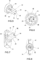
figures 5, 6 and 7, 8 are a pair of perspective views and a pair of front views respectively of a female portion and a male portion associated with a respective actuation element; -
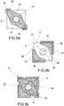
figures 9A, 9B, 9C show schematically the geometric shape in cross-section of the male portion, of the female portion and of both such telescopically mounted portions; -
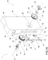
figures 10 ,11 ,12 show three perspective views of an assembly according to the present invention according to different embodiments; -
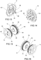
figures 13, 14 are perspective views respectively of a male portion and of a female portion associated with a respective actuation element; -
figures 15, 16 ,17 show respectively two perspective views from opposite sides and a side sectional view of a lock object of the present invention, according to a further possible embodiment. - In the aforementioned tables, the
reference numerals window leaf 20 to a jamb. - Preferably, such door or window leaf is of a sliding type.
-
Such lock lock device 2, 2', asquare pin 18 andactuation elements - According to different embodiments, the side of the
square pin 18 could measure 6 millimeters, 7 millimeters or 8 millimeters. - The
lock device 2, 2' is insertable in afirst leaf seat 10 and comprises abolt 4, movable between a retracted or release configuration and an extracted or locking configuration of theleaf 20 to the jamb. In the variants shown, the first leaf seat is delimited in thethickness 82 of theleaf 20. - It should be noted that in the present description, the terms "retracted" and "extracted" refer to a bolt respectively received within or protruding with respect to a
device body 78, 78' of thelock device 2, 2'. - More specifically, in the locking configuration, the
bolt 4 protrudes from thedevice body 78, 78' (specifically: from afront wall 80, 80' ofsaid body 78, 78') to engage an edge of a counter-plate (not illustrated) associated with the jamb. - According to various embodiments, the
bolt 4 may be rotatable (figure 10 ) or roto-translatable (figure 11 ) with respect to thedevice body 78, 78'. - The
square pin 18 passes through thelock device 2, 2' so as to protrude from both sides of the latter. - In this regard, in the variant shown e.g. in
figure 10 , thelock device 2, 2' delimits a throughseat 60, optionally square, wherein thesquare pin 18 is received. - The
actuation elements square pin 18 and are manually rotatable around a rotation axis R for moving the bolt between said configurations discussed previously. - For example, the actuation elements may comprise at least one knob, at least one pommel, at least one handle 14, at least one emergency actuation element 16 (i.e. a molded/shaped element for coupling in form with a tool or the edge a coin), and their combinations.
- Optionally, the
lock handle casings second leaf seats 30, each of which delimits a leaf-abutment surface 8 and ahousing compartment 12. - The
second leaf seats 30 advantageously communicate with thefirst leaf seat 10. - In the variants shown, the
second leaf seats 30 extend fromopposite side surfaces 90 of theleaf 20 toward the inside (i.e. through the thickness) of the latter. - For example, the leaf-
abutment surface 8 is of a substantially annular shape and may advantageously be delimited by anouter metal ring 88 of thecasing - According to one variant, at least one
casing bottom wall 84 which delimits apin hole 86, in which thesquare pin 18 passes through. - According to a further variant, the
actuation elements casings - According to one embodiment, at least one
lock casing 6', 6" comprises aplastic body second leaf seat 30. - According to such variant, a
finishing element 62 could optionally be connected to theplastic body - According to a further embodiment, a
portion 64 of thefinishing element 62 may be configured to radially force anchoringfins 66 outside of theplastic body second seat 30. - Referring, for example, to the variant of
figure 12 ,such portion 64 could comprise a truncated cone portion of thefinishing element 62. - According to another further embodiment, at least one
lock casing 6 comprises ametallic body 68 comprising externally indentedportions 70 to engage thesecond leaf seat 30. - According to the invention, the
square pin 18 is telescopic and comprises afemale portion 22 comprising one ormore walls 24 which circumscribe apin compartment 26. Thiscompartment 26 receives amale portion 28 of thepin 18 in a sliding manner. - Thus, the telescopic movement between such portions, and hence an adjustment of the length of the
pin 18 as a function of thethickness 82 of theleaf 20, is permitted. - The wall 24 (or plurality of walls) of the
female portion 22 delimits at least onelongitudinal slit 32 wherein themale portion 28 is partly received for a coupling of the latter with thelocking device 2, 2'. - In other words, although telescopically received in the
female portion 22, themale portion 28 also mechanically works on the lock device, as one of its parts protrudes outwardly from thepin compartment 26 to engagesuch device 2, 2' and, more precisely, to be inserted into the throughseat 60. - It follows that, according to one embodiment, the
female portion 22 and themale portion 28 each define anabutment surface seat 60 of thelock device 2, 2'. - In the embodiments illustrated, the
male portion 28 has a substantially ovoidal or ellipsoidal cross-section. - According to one embodiment, the
male portion 28 and/or thefemale portion 22 are made in one piece with therespective actuation element - As diagrammed in the variant of
figure 11 , the casings 6' may be interconnected by means of respective connectingarms square pin 18, and may optionally cooperate with each other in order to surround part of, and optionally retain, the lock device 2'. - According to one embodiment, the connecting
arms - In the variants of
figure 7 or13 , themale portion 28 comprises at least onelongitudinal rib 38 protruding in thelongitudinal slit 32 so thatsuch rib 38 forms an obstacle to the elastic shrinkage ofsuch slit 32. - According to another variant, the
male portion 28 and optionally thelongitudinal rib 38 of such portion is wedged through atapered space 40 delimited by thefemale portion 22 which - in a radial direction Z from the inside to the outside of the square pin 18 - precedes thelongitudinal slit 32. - According to a further variant, the
female portion 22 and themale portion 28 delimit complementarysliding surfaces actuation elements - Referring, for example, to the schematic diagrams of
figure 9 , a square perimeter Q is detectable around thefemale portion 22, which circumscribessuch portion 22. Optionally, in such perimeter Q the part of themale portion 28 protruding in thelongitudinal slit 32 is also inscribed, in particular, thelongitudinal rib 38 according to one of the embodiments discussed. - In the variant schematically diagrammed in
figures 4 and9B , thefemale portion 22 comprises at least a pair ofwalls 24 shaped, for example, in a generally "L" section, delimiting a pair oflongitudinal slits 32 arranged along a diagonal of thesquare pin 18. - According to such variant, the male portion is therefore oriented and protrudes through the diagonal identifiable in the
square pin 18. - According to another variant, the
female portion 22 and themale portion 28 are retained axially through a locking means 46 (such as a threaded means such as a screw) that develops partially in thepin compartment 26 and which engages one end 28' of themale portion 28. - For example, this end 28' could delimit an axial hole 92 (optionally threaded internally) to receive, and preferably retain, the locking means 46.
- According to one advantageous variant, one 16 of said actuation elements delimits an axial through-passage 48 (for example threaded), where the
female portion 22 is joined to saidactuation element 16 with an opening of thepin compartment 26 at least partially aligned with theaxial passage 48, so that the locking means 46 is actuatable from the outside to secure thefemale portion 22 and themale portion 28. - According to one embodiment, the
male portion 28 and/or thefemale portion 22 associated with thecasing 6 are retained axially by means of anelastic ring 72. - Specifically, an
actuation element 16 associated withsuch portion lock collar 94 which passes through thepin hole 86 and delimits aring seat 96 wherein theelastic ring 72 is inserted. - Thus, since the
ring 72 operates on anouter surface 98 of thecasing 6 and theactuation element 16 is at least partially arranged in thehousing compartment 12, themale portion 28 and/or thefemale portion 22 will remain secured to the casing and - through the latter - to theleaf 20. - According to a further embodiment, the
female portion 22 and/or themale portion 28 are retained axially through a shape and/or force coupling of theactuation elements respective casing - By entering more into the specifics and referring, for example, to the variants of
figures 12 or13 , at least oneactuation element outer edge 100, for example of a substantially circular or arc shape, axially retained through locking fins 102 (e.g. elastic) of the casing 6', which operate onsuch edge 100. - The aforementioned objects are also achieved by means of a telescopic
square pin 18, engageable betweenactuation elements lock bolt 4 of alock device 2, 2'. - Such
square pin 18 comprises afemale portion 22 which comprises one ormore walls 24 that circumscribe apin compartment 26 slidably receiving amale portion 28 of thepin 18, where thewall 24 delimits at least onelongitudinal slit 32 wherein themale portion 28 is partly housed by a coupling of the latter with thelock device 2, 2'. - As to the preferred or additional features of this
square pin 18, reference is made to the description above. - The above objectives are finally achieved by means of an
assembly - a door/
window leaf 20, wherein at least onefirst leaf seat 10 is made; and - a
lock first leaf seat 10 to secure such leaf to a jamb, or asquare pin 18 according to the preceding variants passing through thelock device 2, 2'. - Innovatively, the lock object of the present invention is adaptable to different types of doors, as is the square pin that does not require any mechanical machining to be adapted to the thickness of the leaf.
- Advantageously, the lock object of the present invention may be assembled/disassembled in the absence of specific tools; in fact, such lock has been designed with precise and reliable couplings that make the use of screwdrivers and the like superfluous.
- Advantageously, this lock is coupled to the door with a substantially self-locking system which is releasable with bare hands.
- Advantageously, the lock and pin of the present invention may be implemented on existing doors and windows, especially due to their small size and ease of assembly.
- Advantageously, the lock and pin object of the present invention allow it to be used in an extremely wide range of thicknesses, for example from 35 millimeters to approximately 52-54 millimeters.
- In fact, by virtue of coupling both the male portion and the female portion with the locking device, such portions are designed to work even when the male portion lies outside of the compartment of the female portion, but in any case inside the through seat of such device.
- Advantageously, the male portion object of the present invention prevents the female portion from deteriorating.
- Advantageously, the male portion object of the present invention allows a reliable telescopic sliding to be obtained. In addition, the female portion allows the male portion to remain locked in the transverse direction.
- Advantageously, the lock and pin object of the present invention allow one to obtain high mechanical strength in both directions of rotation of the actuation elements.
- Advantageously, the longitudinal extension of the pin object of the present invention may be stopped in different ways depending on the contingencies, and with the dimensions of the means for this object being extremely reduced.
- Advantageously, the modular nature of this lock allows the costs of assembly and storage to be reduced for a variety of different products.
- In the embodiments of the aforementioned lock, square pin and assembly, a person skilled in the art, in order to meet specific needs, might introduce variants or substitutions of elements with others that are functionally equivalent.
- These variants are also contained within the scope of protection as defined by the following claims.
- Furthermore, each variant described as belonging to a possible embodiment may be achieved independently of the other variants described.
Claims (17)
- Lock (1, 1', 1") to secure a leaf (20) of a door or window to a jamb, comprising:- a lock device (2, 2'), insertable in a first leaf seat (10) and comprising a bolt (4), movable between a release configuration and a locking configuration of the leaf (20) to the jamb;- a square pin (18), passing through the lock device (2, 2') so as to protrude from both sides of the latter;- actuation elements (14, 16), for example knobs, each engaged with one end of the square pin (18) and manually rotatable about a rotation axis (R) for moving the bolt between said configurations;wherein said pin (18) is telescopic and comprises a female portion (22) that comprises one or more walls (24) that circumscribe a pin compartment (26) slidably receiving a male portion (28) of said pin (18), said wall (24) delimiting at least one longitudinal slit (32) in which the male portion (28) is partly housed for coupling of the latter with the lock device (2, 2').
- Lock according to the preceding claim, wherein the female portion (22) and the male portion (28) each delimit an abutment surface (34, 36) with a through seat (60), optionally squared, of the lock device (2, 2').
- Lock according to any of the preceding claims, wherein the male portion (28) comprises at least one longitudinal rib (38), projecting in the longitudinal slit (32) so that said rib (38) makes an obstacle to the elastic shrinkage of said slit (32).
- Lock according to any of the preceding claims, optionally when dependent on the preceding claim, wherein the male portion (28), and optionally the longitudinal rib (38) of said portion, is wedged through a tapered space (40) delimited by the female portion (22), which precedes the longitudinal slit (32) in a radial direction (Z) from the inside to the outside of said pin (18).
- Lock according to any of the preceding claims, wherein the female portion (22) and the male portion (28) delimit complementary sliding surfaces (42, 44) of substantially arched shape, to divert the forces transmitted through said actuation elements (14, 16) in a direction with a tangential component.
- Lock according to any of the preceding claims, wherein around the female portion (22) is identifiable a square perimeter (Q) that circumscribes it, in said perimeter (Q) being also inscribed the part of the male portion (28) projecting in the longitudinal slit (32).
- Lock according to any of the preceding claims, comprising at least a pair of walls (24), shaped for example in generically "L" section, which delimit a pair of longitudinal slits (32) disposed along a diagonal of the square pin (18).
- Lock according to any of the preceding claims, wherein the female portion (22) and the male portion (28) are axially retained through a locking means (46) that develops partly in the pin compartment (26) and that engages an end (28') of the male portion (28).
- Lock according to the preceding claim, wherein one (16) of said actuation elements delimits an axial through-passage (48), for example threaded, and wherein the female portion (22) is joined to said actuation element (16) with an opening of the pin compartment (26) at least partially aligned with the axial passage (48), so that the locking means (46) is actuatable from the outside to constrain the female portion (22) and the male portion (28).
- Lock according to any of the preceding claims, comprising a pair of casings (6, 6', 6") for handle, at least partly recessed in second leaf seats (30), each of which delimits a leaf-abutment surface (8) and a housing compartment (12), the actuation elements (14, 16) being at least partly received in the casings (6, 6', 6").
- Lock according to the preceding claim, wherein the female portion (22) and/or the male portion (28) are retained axially through a shape and/or force coupling of the actuation elements (14, 16) in the respective casing (6, 6', 6").
- Lock according to any of claims 10 to 11, wherein at least one of the lock casing (6', 6") comprises a plastic body (56, 58) insertable into the second leaf seat (30), and a finishing element (62) connected to said body (56, 58) in a releasable manner, a portion (64) of said finishing element (62) being configured to force radially outwardly anchoring fins (66) of the plastic body (56, 58) to said second seat (30).
- Lock according to any of claims 10 to 11, wherein at least one of the lock casings (6) comprises a metal body (68), externally comprising indented portions (70) to engage the second leaf seat (30), and wherein the male portion (28) and/or the female portion (22) associated with it is retained axially by an elastic ring (72).
- Lock according to any one of claims 10 to 13, wherein the casings (6') are mutually connected through respective connecting arms (74, 76) in a manner adjustable as a function of the telescopic length of the square pin (18), and cooperate with each other to encircle, and optionally retain, the lock device (2').
- Lock according to any of the preceding claims, wherein the male portion (28) and/or the female portion (22) are made in one piece, for example of a metallic material, with the respective actuation element (14, 16).
- Square pin (18), telescopic, engageable between actuation elements (14, 16) of a lock (1, 1', 1") to transmit the rotations of one of said elements to the bolt (4) of a lock device (2, 2'), said pin (18) comprising a female portion (22) that comprises one or more walls (24) that circumscribe a pin compartment (26) slidably receiving a male portion (28) of said pin (18), the wall (24) delimiting at least one longitudinal slit (32) in which the male portion (28) is partly housed for a coupling of the latter with the lock device (2, 2').
- Assembly (50, 52, 54) comprising:- a leaf (20) of door/window, wherein at least a first leaf seat (10) is made; and- a lock (1, 1', 1") according to any of claims 1 to 15, inserted in the first leaf seat (10) to secure such leaf to a jamb, or a square pin (18) according to claim 16 passing through the lock device (2, 2').
Applications Claiming Priority (1)
| Application Number | Priority Date | Filing Date | Title |
|---|---|---|---|
| ITUA2016A003856A ITUA20163856A1 (en) | 2016-05-27 | 2016-05-27 | LOCK AND ASSEMBLY |
Publications (2)
| Publication Number | Publication Date |
|---|---|
| EP3249140A1 true EP3249140A1 (en) | 2017-11-29 |
| EP3249140B1 EP3249140B1 (en) | 2021-12-01 |
Family
ID=56990835
Family Applications (1)
| Application Number | Title | Priority Date | Filing Date |
|---|---|---|---|
| EP17172887.6A Active EP3249140B1 (en) | 2016-05-27 | 2017-05-24 | Lock and assembly |
Country Status (4)
| Country | Link |
|---|---|
| EP (1) | EP3249140B1 (en) |
| DK (1) | DK3249140T3 (en) |
| ES (1) | ES2907491T3 (en) |
| IT (1) | ITUA20163856A1 (en) |
Cited By (4)
| Publication number | Priority date | Publication date | Assignee | Title |
|---|---|---|---|---|
| IT201800004262A1 (en) * | 2018-04-06 | 2019-10-06 | GROUP-HANDLE WITHOUT SCREWS FOR ONE DOOR | |
| IT202000022438A1 (en) * | 2020-09-23 | 2022-03-23 | S A B Serrature S R L | DOOR LOCK |
| IT202100008783A1 (en) * | 2021-04-08 | 2022-10-08 | Alban Giacomo Spa | HANDLE FOR A SLIDING DOOR AND RELATED ASSEMBLY METHOD |
| GB2614261A (en) * | 2021-12-22 | 2023-07-05 | Uap Ltd | Spindle |
Families Citing this family (1)
| Publication number | Priority date | Publication date | Assignee | Title |
|---|---|---|---|---|
| IT202300016644A1 (en) | 2023-08-03 | 2025-02-03 | S A B Serrature S R L | LOCKING SYSTEM FOR A DOOR OR WINDOW LEAF COMPRISING A LOCK AND A CONCEALED CONNECTING DEVICE |
Citations (7)
| Publication number | Priority date | Publication date | Assignee | Title |
|---|---|---|---|---|
| US2111254A (en) * | 1937-06-12 | 1938-03-15 | Helen M Tong | Knob and spindle connecting device |
| EP0471976A2 (en) * | 1990-08-17 | 1992-02-26 | Brumme, Elke, Dipl.-Oec. | Espagnolette |
| GB2391286A (en) * | 2002-06-20 | 2004-02-04 | Codelocks Ltd | Spindle for connecting door handles to door latch has spring to maintain engagement |
| EP1398435A1 (en) * | 2002-09-11 | 2004-03-17 | Hoppe AG | Handle connection |
| WO2005111347A1 (en) * | 2004-05-19 | 2005-11-24 | Abloy Oy | Divided spindle |
| US20110302971A1 (en) * | 2010-06-09 | 2011-12-15 | Jeanette Vy Bui | Adjustable turn piece extension |
| GB2522610A (en) * | 2013-12-11 | 2015-08-05 | Assa Abloy Ltd | Handle assembly |
-
2016
- 2016-05-27 IT ITUA2016A003856A patent/ITUA20163856A1/en unknown
-
2017
- 2017-05-24 ES ES17172887T patent/ES2907491T3/en active Active
- 2017-05-24 DK DK17172887.6T patent/DK3249140T3/en active
- 2017-05-24 EP EP17172887.6A patent/EP3249140B1/en active Active
Patent Citations (7)
| Publication number | Priority date | Publication date | Assignee | Title |
|---|---|---|---|---|
| US2111254A (en) * | 1937-06-12 | 1938-03-15 | Helen M Tong | Knob and spindle connecting device |
| EP0471976A2 (en) * | 1990-08-17 | 1992-02-26 | Brumme, Elke, Dipl.-Oec. | Espagnolette |
| GB2391286A (en) * | 2002-06-20 | 2004-02-04 | Codelocks Ltd | Spindle for connecting door handles to door latch has spring to maintain engagement |
| EP1398435A1 (en) * | 2002-09-11 | 2004-03-17 | Hoppe AG | Handle connection |
| WO2005111347A1 (en) * | 2004-05-19 | 2005-11-24 | Abloy Oy | Divided spindle |
| US20110302971A1 (en) * | 2010-06-09 | 2011-12-15 | Jeanette Vy Bui | Adjustable turn piece extension |
| GB2522610A (en) * | 2013-12-11 | 2015-08-05 | Assa Abloy Ltd | Handle assembly |
Cited By (6)
| Publication number | Priority date | Publication date | Assignee | Title |
|---|---|---|---|---|
| IT201800004262A1 (en) * | 2018-04-06 | 2019-10-06 | GROUP-HANDLE WITHOUT SCREWS FOR ONE DOOR | |
| IT202000022438A1 (en) * | 2020-09-23 | 2022-03-23 | S A B Serrature S R L | DOOR LOCK |
| WO2022064410A1 (en) * | 2020-09-23 | 2022-03-31 | S.A.B. Serrature S.r.l. | Lock |
| IT202100008783A1 (en) * | 2021-04-08 | 2022-10-08 | Alban Giacomo Spa | HANDLE FOR A SLIDING DOOR AND RELATED ASSEMBLY METHOD |
| EP4071325A1 (en) * | 2021-04-08 | 2022-10-12 | Alban Giacomo S.p.A. | Handle for a sliding door and method for mounting said handle |
| GB2614261A (en) * | 2021-12-22 | 2023-07-05 | Uap Ltd | Spindle |
Also Published As
| Publication number | Publication date |
|---|---|
| DK3249140T3 (en) | 2022-02-21 |
| EP3249140B1 (en) | 2021-12-01 |
| ES2907491T3 (en) | 2022-04-25 |
| ITUA20163856A1 (en) | 2017-11-27 |
Similar Documents
| Publication | Publication Date | Title |
|---|---|---|
| EP3249140B1 (en) | Lock and assembly | |
| US11988030B2 (en) | Hinge assembly | |
| US8147173B2 (en) | Adapter for operating a keyhole saw on a driving machine | |
| US10753121B2 (en) | Privacy lock | |
| EP2466159A1 (en) | Fastening assembly | |
| CZ278980B6 (en) | Cylindrical lock | |
| CN102884262A (en) | Handle Assemblies for Double Wall Doors | |
| EP3290623B1 (en) | A locking device | |
| WO2017035178A1 (en) | Adjustable pressure relief latch | |
| US20170333966A1 (en) | Sheet metal dent repair tool exchange handle | |
| EP2385203B1 (en) | Locking hinge | |
| WO2017007890A1 (en) | Adjustable backset cylindrical latch | |
| US11555330B2 (en) | Privacy lock | |
| EP1717135B1 (en) | Bicycle lock | |
| EP3070208B1 (en) | Operating assembly for an operating unit of a concealed sanitary fitting | |
| AU2017390000B2 (en) | Bevel locking system | |
| EP3630415B1 (en) | Torque wrench and reaction arm assembly with safety tether | |
| US5662365A (en) | Lockset | |
| US20180073270A1 (en) | Lock Apparatus | |
| EP1462198B1 (en) | Quick change mandrel assembly for hole saw and drill bit | |
| EP1457291B1 (en) | Connection of tool handle with tool bit | |
| GB2387874A (en) | Anchor apparatus | |
| US10107006B2 (en) | Door knob assembly | |
| GB1576930A (en) | Apparatus for securing a rotary shaft against axial displacement | |
| ES2814283T3 (en) | Shielding element fixing mechanism |
Legal Events
| Date | Code | Title | Description |
|---|---|---|---|
| PUAI | Public reference made under article 153(3) epc to a published international application that has entered the european phase |
Free format text: ORIGINAL CODE: 0009012 |
|
| STAA | Information on the status of an ep patent application or granted ep patent |
Free format text: STATUS: THE APPLICATION HAS BEEN PUBLISHED |
|
| AK | Designated contracting states |
Kind code of ref document: A1 Designated state(s): AL AT BE BG CH CY CZ DE DK EE ES FI FR GB GR HR HU IE IS IT LI LT LU LV MC MK MT NL NO PL PT RO RS SE SI SK SM TR |
|
| AX | Request for extension of the european patent |
Extension state: BA ME |
|
| STAA | Information on the status of an ep patent application or granted ep patent |
Free format text: STATUS: REQUEST FOR EXAMINATION WAS MADE |
|
| 17P | Request for examination filed |
Effective date: 20180525 |
|
| RBV | Designated contracting states (corrected) |
Designated state(s): AL AT BE BG CH CY CZ DE DK EE ES FI FR GB GR HR HU IE IS IT LI LT LU LV MC MK MT NL NO PL PT RO RS SE SI SK SM TR |
|
| GRAP | Despatch of communication of intention to grant a patent |
Free format text: ORIGINAL CODE: EPIDOSNIGR1 |
|
| STAA | Information on the status of an ep patent application or granted ep patent |
Free format text: STATUS: GRANT OF PATENT IS INTENDED |
|
| INTG | Intention to grant announced |
Effective date: 20210702 |
|
| GRAS | Grant fee paid |
Free format text: ORIGINAL CODE: EPIDOSNIGR3 |
|
| GRAA | (expected) grant |
Free format text: ORIGINAL CODE: 0009210 |
|
| STAA | Information on the status of an ep patent application or granted ep patent |
Free format text: STATUS: THE PATENT HAS BEEN GRANTED |
|
| AK | Designated contracting states |
Kind code of ref document: B1 Designated state(s): AL AT BE BG CH CY CZ DE DK EE ES FI FR GB GR HR HU IE IS IT LI LT LU LV MC MK MT NL NO PL PT RO RS SE SI SK SM TR |
|
| REG | Reference to a national code |
Ref country code: GB Ref legal event code: FG4D |
|
| REG | Reference to a national code |
Ref country code: AT Ref legal event code: REF Ref document number: 1451913 Country of ref document: AT Kind code of ref document: T Effective date: 20211215 Ref country code: CH Ref legal event code: EP |
|
| REG | Reference to a national code |
Ref country code: IE Ref legal event code: FG4D |
|
| REG | Reference to a national code |
Ref country code: DE Ref legal event code: R096 Ref document number: 602017050052 Country of ref document: DE |
|
| REG | Reference to a national code |
Ref country code: DK Ref legal event code: T3 Effective date: 20220214 |
|
| REG | Reference to a national code |
Ref country code: LT Ref legal event code: MG9D |
|
| REG | Reference to a national code |
Ref country code: NL Ref legal event code: MP Effective date: 20211201 |
|
| REG | Reference to a national code |
Ref country code: ES Ref legal event code: FG2A Ref document number: 2907491 Country of ref document: ES Kind code of ref document: T3 Effective date: 20220425 |
|
| PG25 | Lapsed in a contracting state [announced via postgrant information from national office to epo] |
Ref country code: RS Free format text: LAPSE BECAUSE OF FAILURE TO SUBMIT A TRANSLATION OF THE DESCRIPTION OR TO PAY THE FEE WITHIN THE PRESCRIBED TIME-LIMIT Effective date: 20211201 Ref country code: LT Free format text: LAPSE BECAUSE OF FAILURE TO SUBMIT A TRANSLATION OF THE DESCRIPTION OR TO PAY THE FEE WITHIN THE PRESCRIBED TIME-LIMIT Effective date: 20211201 Ref country code: FI Free format text: LAPSE BECAUSE OF FAILURE TO SUBMIT A TRANSLATION OF THE DESCRIPTION OR TO PAY THE FEE WITHIN THE PRESCRIBED TIME-LIMIT Effective date: 20211201 Ref country code: BG Free format text: LAPSE BECAUSE OF FAILURE TO SUBMIT A TRANSLATION OF THE DESCRIPTION OR TO PAY THE FEE WITHIN THE PRESCRIBED TIME-LIMIT Effective date: 20220301 |
|
| PG25 | Lapsed in a contracting state [announced via postgrant information from national office to epo] |
Ref country code: SE Free format text: LAPSE BECAUSE OF FAILURE TO SUBMIT A TRANSLATION OF THE DESCRIPTION OR TO PAY THE FEE WITHIN THE PRESCRIBED TIME-LIMIT Effective date: 20211201 Ref country code: PL Free format text: LAPSE BECAUSE OF FAILURE TO SUBMIT A TRANSLATION OF THE DESCRIPTION OR TO PAY THE FEE WITHIN THE PRESCRIBED TIME-LIMIT Effective date: 20211201 Ref country code: NO Free format text: LAPSE BECAUSE OF FAILURE TO SUBMIT A TRANSLATION OF THE DESCRIPTION OR TO PAY THE FEE WITHIN THE PRESCRIBED TIME-LIMIT Effective date: 20220301 Ref country code: LV Free format text: LAPSE BECAUSE OF FAILURE TO SUBMIT A TRANSLATION OF THE DESCRIPTION OR TO PAY THE FEE WITHIN THE PRESCRIBED TIME-LIMIT Effective date: 20211201 Ref country code: HR Free format text: LAPSE BECAUSE OF FAILURE TO SUBMIT A TRANSLATION OF THE DESCRIPTION OR TO PAY THE FEE WITHIN THE PRESCRIBED TIME-LIMIT Effective date: 20211201 Ref country code: GR Free format text: LAPSE BECAUSE OF FAILURE TO SUBMIT A TRANSLATION OF THE DESCRIPTION OR TO PAY THE FEE WITHIN THE PRESCRIBED TIME-LIMIT Effective date: 20220302 |
|
| PG25 | Lapsed in a contracting state [announced via postgrant information from national office to epo] |
Ref country code: NL Free format text: LAPSE BECAUSE OF FAILURE TO SUBMIT A TRANSLATION OF THE DESCRIPTION OR TO PAY THE FEE WITHIN THE PRESCRIBED TIME-LIMIT Effective date: 20211201 |
|
| PG25 | Lapsed in a contracting state [announced via postgrant information from national office to epo] |
Ref country code: SM Free format text: LAPSE BECAUSE OF FAILURE TO SUBMIT A TRANSLATION OF THE DESCRIPTION OR TO PAY THE FEE WITHIN THE PRESCRIBED TIME-LIMIT Effective date: 20211201 Ref country code: SK Free format text: LAPSE BECAUSE OF FAILURE TO SUBMIT A TRANSLATION OF THE DESCRIPTION OR TO PAY THE FEE WITHIN THE PRESCRIBED TIME-LIMIT Effective date: 20211201 Ref country code: RO Free format text: LAPSE BECAUSE OF FAILURE TO SUBMIT A TRANSLATION OF THE DESCRIPTION OR TO PAY THE FEE WITHIN THE PRESCRIBED TIME-LIMIT Effective date: 20211201 Ref country code: PT Free format text: LAPSE BECAUSE OF FAILURE TO SUBMIT A TRANSLATION OF THE DESCRIPTION OR TO PAY THE FEE WITHIN THE PRESCRIBED TIME-LIMIT Effective date: 20220401 Ref country code: EE Free format text: LAPSE BECAUSE OF FAILURE TO SUBMIT A TRANSLATION OF THE DESCRIPTION OR TO PAY THE FEE WITHIN THE PRESCRIBED TIME-LIMIT Effective date: 20211201 Ref country code: CZ Free format text: LAPSE BECAUSE OF FAILURE TO SUBMIT A TRANSLATION OF THE DESCRIPTION OR TO PAY THE FEE WITHIN THE PRESCRIBED TIME-LIMIT Effective date: 20211201 |
|
| REG | Reference to a national code |
Ref country code: DE Ref legal event code: R097 Ref document number: 602017050052 Country of ref document: DE |
|
| PG25 | Lapsed in a contracting state [announced via postgrant information from national office to epo] |
Ref country code: IS Free format text: LAPSE BECAUSE OF FAILURE TO SUBMIT A TRANSLATION OF THE DESCRIPTION OR TO PAY THE FEE WITHIN THE PRESCRIBED TIME-LIMIT Effective date: 20220401 |
|
| PLBE | No opposition filed within time limit |
Free format text: ORIGINAL CODE: 0009261 |
|
| STAA | Information on the status of an ep patent application or granted ep patent |
Free format text: STATUS: NO OPPOSITION FILED WITHIN TIME LIMIT |
|
| PG25 | Lapsed in a contracting state [announced via postgrant information from national office to epo] |
Ref country code: AL Free format text: LAPSE BECAUSE OF FAILURE TO SUBMIT A TRANSLATION OF THE DESCRIPTION OR TO PAY THE FEE WITHIN THE PRESCRIBED TIME-LIMIT Effective date: 20211201 |
|
| 26N | No opposition filed |
Effective date: 20220902 |
|
| PG25 | Lapsed in a contracting state [announced via postgrant information from national office to epo] |
Ref country code: SI Free format text: LAPSE BECAUSE OF FAILURE TO SUBMIT A TRANSLATION OF THE DESCRIPTION OR TO PAY THE FEE WITHIN THE PRESCRIBED TIME-LIMIT Effective date: 20211201 |
|
| REG | Reference to a national code |
Ref country code: CH Ref legal event code: PL |
|
| PG25 | Lapsed in a contracting state [announced via postgrant information from national office to epo] |
Ref country code: MC Free format text: LAPSE BECAUSE OF FAILURE TO SUBMIT A TRANSLATION OF THE DESCRIPTION OR TO PAY THE FEE WITHIN THE PRESCRIBED TIME-LIMIT Effective date: 20211201 Ref country code: LU Free format text: LAPSE BECAUSE OF NON-PAYMENT OF DUE FEES Effective date: 20220524 Ref country code: LI Free format text: LAPSE BECAUSE OF NON-PAYMENT OF DUE FEES Effective date: 20220531 Ref country code: CH Free format text: LAPSE BECAUSE OF NON-PAYMENT OF DUE FEES Effective date: 20220531 |
|
| PG25 | Lapsed in a contracting state [announced via postgrant information from national office to epo] |
Ref country code: IE Free format text: LAPSE BECAUSE OF NON-PAYMENT OF DUE FEES Effective date: 20220524 |
|
| REG | Reference to a national code |
Ref country code: AT Ref legal event code: UEP Ref document number: 1451913 Country of ref document: AT Kind code of ref document: T Effective date: 20211201 |
|
| P01 | Opt-out of the competence of the unified patent court (upc) registered |
Effective date: 20230526 |
|
| PG25 | Lapsed in a contracting state [announced via postgrant information from national office to epo] |
Ref country code: HU Free format text: LAPSE BECAUSE OF FAILURE TO SUBMIT A TRANSLATION OF THE DESCRIPTION OR TO PAY THE FEE WITHIN THE PRESCRIBED TIME-LIMIT; INVALID AB INITIO Effective date: 20170524 |
|
| PG25 | Lapsed in a contracting state [announced via postgrant information from national office to epo] |
Ref country code: MK Free format text: LAPSE BECAUSE OF FAILURE TO SUBMIT A TRANSLATION OF THE DESCRIPTION OR TO PAY THE FEE WITHIN THE PRESCRIBED TIME-LIMIT Effective date: 20211201 Ref country code: CY Free format text: LAPSE BECAUSE OF FAILURE TO SUBMIT A TRANSLATION OF THE DESCRIPTION OR TO PAY THE FEE WITHIN THE PRESCRIBED TIME-LIMIT Effective date: 20211201 |
|
| PG25 | Lapsed in a contracting state [announced via postgrant information from national office to epo] |
Ref country code: TR Free format text: LAPSE BECAUSE OF FAILURE TO SUBMIT A TRANSLATION OF THE DESCRIPTION OR TO PAY THE FEE WITHIN THE PRESCRIBED TIME-LIMIT Effective date: 20211201 |
|
| PG25 | Lapsed in a contracting state [announced via postgrant information from national office to epo] |
Ref country code: MT Free format text: LAPSE BECAUSE OF FAILURE TO SUBMIT A TRANSLATION OF THE DESCRIPTION OR TO PAY THE FEE WITHIN THE PRESCRIBED TIME-LIMIT Effective date: 20211201 |
|
| PGFP | Annual fee paid to national office [announced via postgrant information from national office to epo] |
Ref country code: GB Payment date: 20260312 Year of fee payment: 10 |
|
| PGFP | Annual fee paid to national office [announced via postgrant information from national office to epo] |
Ref country code: IT Payment date: 20260306 Year of fee payment: 10 |
|
| PGFP | Annual fee paid to national office [announced via postgrant information from national office to epo] |
Ref country code: ES Payment date: 20260601 Year of fee payment: 10 |
|
| PGFP | Annual fee paid to national office [announced via postgrant information from national office to epo] |
Ref country code: DK Payment date: 20260522 Year of fee payment: 10 |
|
| PGFP | Annual fee paid to national office [announced via postgrant information from national office to epo] |
Ref country code: DE Payment date: 20260521 Year of fee payment: 10 |
|
| PGFP | Annual fee paid to national office [announced via postgrant information from national office to epo] |
Ref country code: AT Payment date: 20260519 Year of fee payment: 10 |
|
| PGFP | Annual fee paid to national office [announced via postgrant information from national office to epo] |
Ref country code: BE Payment date: 20260520 Year of fee payment: 10 |
|
| PGFP | Annual fee paid to national office [announced via postgrant information from national office to epo] |
Ref country code: FR Payment date: 20260430 Year of fee payment: 10 |