EP3249115A1 - Hybrid construction machine - Google Patents
Hybrid construction machine Download PDFInfo
- Publication number
- EP3249115A1 EP3249115A1 EP15878921.4A EP15878921A EP3249115A1 EP 3249115 A1 EP3249115 A1 EP 3249115A1 EP 15878921 A EP15878921 A EP 15878921A EP 3249115 A1 EP3249115 A1 EP 3249115A1
- Authority
- EP
- European Patent Office
- Prior art keywords
- electricity storage
- mode
- storage rate
- engine
- revolving
- Prior art date
- Legal status (The legal status is an assumption and is not a legal conclusion. Google has not performed a legal analysis and makes no representation as to the accuracy of the status listed.)
- Granted
Links
- 238000010276 construction Methods 0.000 title claims description 18
- 230000005611 electricity Effects 0.000 claims abstract description 193
- 230000008859 change Effects 0.000 claims description 38
- 230000007423 decrease Effects 0.000 claims description 3
- 230000007246 mechanism Effects 0.000 abstract description 14
- 230000008929 regeneration Effects 0.000 description 12
- 238000011069 regeneration method Methods 0.000 description 12
- 101100388057 Mus musculus Poln gene Proteins 0.000 description 10
- 230000001172 regenerating effect Effects 0.000 description 10
- 239000003921 oil Substances 0.000 description 7
- 238000010586 diagram Methods 0.000 description 6
- 239000000446 fuel Substances 0.000 description 6
- 230000015556 catabolic process Effects 0.000 description 5
- 238000006731 degradation reaction Methods 0.000 description 5
- 238000010248 power generation Methods 0.000 description 5
- 230000004044 response Effects 0.000 description 5
- HBBGRARXTFLTSG-UHFFFAOYSA-N Lithium ion Chemical compound [Li+] HBBGRARXTFLTSG-UHFFFAOYSA-N 0.000 description 4
- 229910001416 lithium ion Inorganic materials 0.000 description 4
- 238000000034 method Methods 0.000 description 4
- 230000009194 climbing Effects 0.000 description 3
- 230000008569 process Effects 0.000 description 3
- PXHVJJICTQNCMI-UHFFFAOYSA-N Nickel Chemical compound [Ni] PXHVJJICTQNCMI-UHFFFAOYSA-N 0.000 description 2
- 239000003990 capacitor Substances 0.000 description 2
- 239000010720 hydraulic oil Substances 0.000 description 2
- 230000000717 retained effect Effects 0.000 description 2
- 230000000007 visual effect Effects 0.000 description 2
- XLYOFNOQVPJJNP-UHFFFAOYSA-N water Substances O XLYOFNOQVPJJNP-UHFFFAOYSA-N 0.000 description 2
- UFHFLCQGNIYNRP-UHFFFAOYSA-N Hydrogen Chemical compound [H][H] UFHFLCQGNIYNRP-UHFFFAOYSA-N 0.000 description 1
- 238000013459 approach Methods 0.000 description 1
- OJIJEKBXJYRIBZ-UHFFFAOYSA-N cadmium nickel Chemical compound [Ni].[Cd] OJIJEKBXJYRIBZ-UHFFFAOYSA-N 0.000 description 1
- 238000002485 combustion reaction Methods 0.000 description 1
- 238000001816 cooling Methods 0.000 description 1
- 239000000498 cooling water Substances 0.000 description 1
- 229910052739 hydrogen Inorganic materials 0.000 description 1
- 239000001257 hydrogen Substances 0.000 description 1
- 230000006698 induction Effects 0.000 description 1
- 229910052759 nickel Inorganic materials 0.000 description 1
- 230000009467 reduction Effects 0.000 description 1
- 239000004576 sand Substances 0.000 description 1
- 230000001360 synchronised effect Effects 0.000 description 1
Images


Classifications
-
- B—PERFORMING OPERATIONS; TRANSPORTING
- B60—VEHICLES IN GENERAL
- B60W—CONJOINT CONTROL OF VEHICLE SUB-UNITS OF DIFFERENT TYPE OR DIFFERENT FUNCTION; CONTROL SYSTEMS SPECIALLY ADAPTED FOR HYBRID VEHICLES; ROAD VEHICLE DRIVE CONTROL SYSTEMS FOR PURPOSES NOT RELATED TO THE CONTROL OF A PARTICULAR SUB-UNIT
- B60W20/00—Control systems specially adapted for hybrid vehicles
- B60W20/10—Controlling the power contribution of each of the prime movers to meet required power demand
- B60W20/13—Controlling the power contribution of each of the prime movers to meet required power demand in order to stay within battery power input or output limits; in order to prevent overcharging or battery depletion
-
- E—FIXED CONSTRUCTIONS
- E02—HYDRAULIC ENGINEERING; FOUNDATIONS; SOIL SHIFTING
- E02F—DREDGING; SOIL-SHIFTING
- E02F9/00—Component parts of dredgers or soil-shifting machines, not restricted to one of the kinds covered by groups E02F3/00 - E02F7/00
- E02F9/08—Superstructures; Supports for superstructures
- E02F9/10—Supports for movable superstructures mounted on travelling or walking gears or on other superstructures
- E02F9/12—Slewing or traversing gears
- E02F9/121—Turntables, i.e. structure rotatable about 360°
- E02F9/123—Drives or control devices specially adapted therefor
-
- E—FIXED CONSTRUCTIONS
- E02—HYDRAULIC ENGINEERING; FOUNDATIONS; SOIL SHIFTING
- E02F—DREDGING; SOIL-SHIFTING
- E02F9/00—Component parts of dredgers or soil-shifting machines, not restricted to one of the kinds covered by groups E02F3/00 - E02F7/00
- E02F9/20—Drives; Control devices
- E02F9/2058—Electric or electro-mechanical or mechanical control devices of vehicle sub-units
- E02F9/2062—Control of propulsion units
- E02F9/2075—Control of propulsion units of the hybrid type
-
- E—FIXED CONSTRUCTIONS
- E02—HYDRAULIC ENGINEERING; FOUNDATIONS; SOIL SHIFTING
- E02F—DREDGING; SOIL-SHIFTING
- E02F9/00—Component parts of dredgers or soil-shifting machines, not restricted to one of the kinds covered by groups E02F3/00 - E02F7/00
- E02F9/20—Drives; Control devices
- E02F9/2058—Electric or electro-mechanical or mechanical control devices of vehicle sub-units
- E02F9/2091—Control of energy storage means for electrical energy, e.g. battery or capacitors
-
- E—FIXED CONSTRUCTIONS
- E02—HYDRAULIC ENGINEERING; FOUNDATIONS; SOIL SHIFTING
- E02F—DREDGING; SOIL-SHIFTING
- E02F9/00—Component parts of dredgers or soil-shifting machines, not restricted to one of the kinds covered by groups E02F3/00 - E02F7/00
- E02F9/20—Drives; Control devices
- E02F9/2058—Electric or electro-mechanical or mechanical control devices of vehicle sub-units
- E02F9/2095—Control of electric, electro-mechanical or mechanical equipment not otherwise provided for, e.g. ventilators, electro-driven fans
-
- E—FIXED CONSTRUCTIONS
- E02—HYDRAULIC ENGINEERING; FOUNDATIONS; SOIL SHIFTING
- E02F—DREDGING; SOIL-SHIFTING
- E02F9/00—Component parts of dredgers or soil-shifting machines, not restricted to one of the kinds covered by groups E02F3/00 - E02F7/00
- E02F9/26—Indicating devices
-
- E—FIXED CONSTRUCTIONS
- E02—HYDRAULIC ENGINEERING; FOUNDATIONS; SOIL SHIFTING
- E02F—DREDGING; SOIL-SHIFTING
- E02F3/00—Dredgers; Soil-shifting machines
- E02F3/04—Dredgers; Soil-shifting machines mechanically-driven
- E02F3/28—Dredgers; Soil-shifting machines mechanically-driven with digging tools mounted on a dipper- or bucket-arm, i.e. there is either one arm or a pair of arms, e.g. dippers, buckets
- E02F3/30—Dredgers; Soil-shifting machines mechanically-driven with digging tools mounted on a dipper- or bucket-arm, i.e. there is either one arm or a pair of arms, e.g. dippers, buckets with a dipper-arm pivoted on a cantilever beam, i.e. boom
- E02F3/32—Dredgers; Soil-shifting machines mechanically-driven with digging tools mounted on a dipper- or bucket-arm, i.e. there is either one arm or a pair of arms, e.g. dippers, buckets with a dipper-arm pivoted on a cantilever beam, i.e. boom working downwardly and towards the machine, e.g. with backhoes
-
- E—FIXED CONSTRUCTIONS
- E02—HYDRAULIC ENGINEERING; FOUNDATIONS; SOIL SHIFTING
- E02F—DREDGING; SOIL-SHIFTING
- E02F9/00—Component parts of dredgers or soil-shifting machines, not restricted to one of the kinds covered by groups E02F3/00 - E02F7/00
- E02F9/20—Drives; Control devices
- E02F9/22—Hydraulic or pneumatic drives
- E02F9/2246—Control of prime movers, e.g. depending on the hydraulic load of work tools
-
- E—FIXED CONSTRUCTIONS
- E02—HYDRAULIC ENGINEERING; FOUNDATIONS; SOIL SHIFTING
- E02F—DREDGING; SOIL-SHIFTING
- E02F9/00—Component parts of dredgers or soil-shifting machines, not restricted to one of the kinds covered by groups E02F3/00 - E02F7/00
- E02F9/20—Drives; Control devices
- E02F9/22—Hydraulic or pneumatic drives
- E02F9/2264—Arrangements or adaptations of elements for hydraulic drives
- E02F9/2271—Actuators and supports therefor and protection therefor
-
- E—FIXED CONSTRUCTIONS
- E02—HYDRAULIC ENGINEERING; FOUNDATIONS; SOIL SHIFTING
- E02F—DREDGING; SOIL-SHIFTING
- E02F9/00—Component parts of dredgers or soil-shifting machines, not restricted to one of the kinds covered by groups E02F3/00 - E02F7/00
- E02F9/20—Drives; Control devices
- E02F9/22—Hydraulic or pneumatic drives
- E02F9/2278—Hydraulic circuits
- E02F9/2296—Systems with a variable displacement pump
Definitions
- the present invention relates to a hybrid construction machine on which an engine and a motor generator are mounted.
- a hybrid construction machine provided with a motor generator that is jointed mechanically to an engine and a hydraulic pump, and an electricity storage device such as an lithium ion battery or capacitor and the like (for example, refer to Patent Document 1).
- the motor generator has a function of charging power generated by a driving force of the engine in the electricity storage device or assisting in the engine by power running which uses power of the electricity storage device.
- Many hybrid construction machines are provided with an electric motor separated from the motor generator, and the electric motor acts for or assists in an operation of a hydraulic actuator.
- the electric motor performs or assists the revolving operation of an upper revolving structure by power supply to the electric motor, and braking energy at a revolving stop is regenerated to perform a charge of the electricity storage device.
- Patent Document 1 discloses the configuration of highly efficiently collecting regeneration energy by appropriately controlling an electricity storage amount in the electricity storage device.
- the next operation of a working mechanism or the upper revolving structure is estimated based upon operating information of an operator and a target electricity storage amount is set based upon an estimation value of the regeneration power calculated from the estimated operation.
- Patent Document 1 Japanese Patent Laid-Open No. 2012-82644 A
- the target electricity storage rate is set based upon a relationship between the regeneration energy and the electricity storage amount of the electricity storage device.
- the degradation of the electricity storage device due to repetition of the charge/discharge is not considered, there is a possibility that the lifetime of the electricity storage device degrades.
- the target electricity storage amount when the target electricity storage amount is set to be low, it is possible to use the electricity storage device for a long period.
- the target electricity storage amount of the electricity storage device is always set to a low value, for example, in a case where a heavy load work continues, energy to be supplied to the electric motor becomes insufficient, possibly causing a problem with an operation of the working mechanism or the like.
- the present invention is made in view of the aforementioned problems in the conventional art, and an object of the present invention is to provide a hybrid construction machine that can suppress a degradation of an electricity storage device and perform a desired vehicle body movement.
- a hybrid hydraulic excavator 1 (hereinafter, referred to as "hydraulic excavator 1") is provided with an engine 21 and a motor generator 27 to be described later.
- the hydraulic excavator 1 includes an automotive lower traveling structure 2 of a crawler type, a revolving device 3 that is provided on the lower traveling structure 2, an upper revolving structure 4 that is rotatably mounted on the lower traveling structure 2 through the revolving device 3, and a working mechanism 11 that is provided in the front side of the upper revolving structure 4 and performs an excavating operation of earth and sand and the like.
- the lower traveling structure 2 and the upper revolving structure 4 configure a vehicle body of the hydraulic excavator 1.
- the upper revolving structure 4 includes a housing cover 6 that is provided on the revolving frame 5 to accommodate an engine 21 and the like, and a cab 7 for an operator getting in.
- a housing cover 6 that is provided on the revolving frame 5 to accommodate an engine 21 and the like, and a cab 7 for an operator getting in.
- an operator's seat 8 on which an operator sits is provided in the cab 7, and an traveling operation device 9 that is composed of an operating lever, an operating pedal and the like, and an working operation device 10 that is composed of an operating lever and the like are provided in the periphery of the operator's seat 8.
- the operation devices 9, 10 are respectively provided with operating amount sensors 9A, 10A that detect their operating amounts (lever operating amount OA).
- the operating amount sensors 9A, 10A configure a vehicle body operating state detecting device that detects an operating state of the vehicle body such as a traveling operation of the lower traveling structure 2, a revolving operation of the upper revolving structure 4 or a lifting/tilting operation (excavating operation) of the working mechanism 11 and the like, for example. Further, an in-vehicle monitor 39 to be described later is provided in the cab 7.
- the working mechanism 11 is configured of, for example, a boom 11A, an arm 11B, a bucket 11C, and a boom cylinder 11D, an arm cylinder 11E and a bucket cylinder 11F for driving them.
- the boom 11A, the arm 11B and the bucket 11C are pinned to each other.
- the working mechanism 11 is attached to the revolving frame 5, and extends or contracts the cylinders 11D to 11F to perform a lifting/tilting movement.
- the hydraulic excavator 1 is provided thereon with an electric system that controls a motor generator 27 and the like, and a hydraulic system that controls operations of the working mechanism 11 and the like.
- an explanation will be made of the system configuration in the hydraulic excavator 1 with reference to Fig. 2 to Fig. 9 .
- the engine 21 is mounted on the revolving frame 5.
- the engine 21 is configured of an internal combustion engine such as a diesel engine and the like, for example.
- a hydraulic pump 23 and the motor generator 27, which will be described later, are attached mechanically to the output side of the engine 21 for serial connection.
- the hydraulic pump 23 and the motor generator 27 are driven by the engine 21.
- an operation of the engine 21 is controlled by an engine control unit 22 (hereinafter, referred to as "ECU 22").
- the ECU 22 controls a rotational speed (engine rotational number) of the engine 21 based upon an engine rotational number command ⁇ e from an HCU 36.
- the maximum output of the engine 21 is made smaller than the maximum power of the hydraulic pump 23, for example.
- the hydraulic pump 23 is driven by the engine 21.
- the hydraulic pump 23 pressurizes hydraulic oil reserved in a tank (not shown), which is supplied to a traveling hydraulic motor 25, a revolving hydraulic motor 26, the cylinders 11D to 11F of the working mechanism 11, and the like as pressurized oil.
- the hydraulic pump 23 is provided with a load sensor 23A.
- the load sensor 23A detects a pump load PL to be outputted to the HCU 36 to be described later.
- the hydraulic pump 23 is connected through a control valve 24 to the traveling hydraulic motor 25, the revolving hydraulic motor 26, and the cylinders 11D to 11F as hydraulic actuators.
- the control valve 24 selectively supplies or discharges the pressurized oil supplied from the hydraulic pump 23 to the traveling hydraulic motor 25, the revolving hydraulic motor 26, and the cylinders 11D to 11F in response to operations to the traveling operation device 9 and the working operation device 10.
- the pressurized oil is supplied to the traveling hydraulic motor 25 from the hydraulic pump 23 in response to an operation of the traveling operation device 9.
- the traveling hydraulic motor 25 drives/travels the lower traveling structure 2.
- the pressurized oil is supplied to the revolving hydraulic motor 26 from the hydraulic pump 23 in response to an operation of the working operation device 10.
- the revolving hydraulic motor 26 operates/revolves the upper revolving structure 4.
- the pressurized oil is supplied to the cylinders 11D to 11F from the hydraulic pump 23 in response to the operation of the working operation device 10.
- the cylinders 11D to 11F lift/tilt the working mechanism 11.
- the motor generator 27 is driven by the engine 21.
- the motor generator 27 is configured of, for example, a synchronous electric motor and the like.
- the motor generator 27 plays two roles of power generation (regeneration) of performing power supply to the electricity storage device 31 and the revolving electric motor 33 by acting as an electric generator by use of the engine 21 as a power source, and power running of assisting in drives of the engine 21 and the hydraulic pump 23 by acting as a motor by use of power from the electricity storage device 31 and the revolving electric motor 33 as a power source.
- assist torque of the motor generator 27 is added to torque of the engine 21 corresponding to the condition, and the hydraulic pump 23 is driven by the engine torque and the assist torque.
- An operation of the working mechanism 11, a travel of the vehicle and the like are performed by the pressurized oil supplied from the hydraulic pump 23.
- the motor generator 27 is connected to a pair of DC buses 29A, 29B through a first inverter 28.
- the first inverter 28 is configured by use of a plurality of switching elements such as a transistor and an insulating gate bipolar transistor (IGBT) and the like, for example, and ON/OFF of each of the switching elements is controlled by a motor generator control unit 30 (hereinafter, referred to as "MGCU 30").
- the DC buses 29A, 29B are paired at a positive terminal side and a negative terminal side, and, for example, a DC voltage of approximately several hundred V is applied thereto.
- the first inverter 28 converts AC power from the motor generator 27 into DC power, which is supplied to the electricity storage device 31 or the revolving electric motor 33.
- the first inverter 28 converts DC power of the DC buses 29A, 29B into AC power, which is supplied to the motor generator 27.
- the MGCU 30 controls ON/OFF of each of the switching elements in the first inverter 28 based upon a motor generator running/generating power command Wmg from the HUB 36. Thereby, the MGCU 30 controls generator power at the power generation of the motor generator 27 or drive power at the power running of the motor generator 27.
- the electricity storage device 31 is connected electrically to the motor generator 27 through the first inverter 28.
- the electricity storage device 31 is configured of, for example, a lithium ion battery and is connected to the DC buses 29A, 29B.
- the electricity storage device 31 charges power supplied from the motor generator 27 at the power generation of the motor generator 27 and supplies drive power toward the motor generator 27 at the power running (at the assist drive) of the motor generator 27.
- the electricity storage device 31 charges regeneration power supplied from the revolving electric motor 33 at the regeneration of the revolving electric motor 33 and supplies drive power toward the revolving electric motor 33 at the power running of the revolving electric motor 33.
- the electricity storage device 31 stores the power generated by the motor generator 27, and further, absorbs the regeneration power generated by the revolving electric motor 33 at the revolving braking of the hydraulic excavator 1 to hold the voltage of the DC buses 29A, 29B to be constant.
- a charge operation or a discharge operation of the electricity storage device 31 is controlled by a battery control unit 32 (hereinafter, referred to as "BCU 32").
- the BCU 32 detects a battery electricity storage rate SOC of the electricity storage device 31 to be outputted to the HCU 36, and controls the charge/discharge of the electricity storage device 31 such that the battery electricity storage rate SOC becomes a target electricity storage rate SOC0 to be outputted from the HCU 36.
- a lithium ion battery for example, having a voltage of 350 V, a discharge capacity of approximately 5 Ah, approximately 30% to 70% of an appropriate use range of the battery electricity storage rate SOC (electricity storage rate) is used in the electricity storage device 31.
- the appropriate use range of the battery electricity storage rate SOC and the like are not limited to the above values, but are set as needed in accordance with a specification of the electricity storage device 31 or the like.
- the revolving electric motor 33 is driven by the power of the motor generator 27 or the electricity storage device 31.
- the revolving electric motor 33 is configured of a three-phase induction motor, for example, and is provided on the revolving frame 5 together with the revolving hydraulic motor 26.
- the revolving electric motor 33 drives the revolving device 3 in cooperation with the revolving hydraulic motor 26.
- the revolving electric motor 33 is connected to the DC buses 29A, 29B through the second inverter 34.
- the revolving electric motor 33 plays two roles of power running of being driven/rotated by receiving power from the electricity storage device 31 or the motor generator 27, and regeneration of charging the electricity storage device 31 by generating power with extra torque at the revolving braking. Therefore, the power from the motor generator 27 and the like is supplied through the DC buses 29A, 29B to the revolving electric motor 33 at the power running.
- the revolving electric motor 33 generates rotational torque in response to an operation of the working operation device 10 to assist in a drive of the revolving hydraulic motor 26, and drives the revolving device 3 to perform a revolving operation of the upper revolving structure 4.
- the second inverter 34 is, as similar to the first inverter 28, configured using a plurality of switching elements. ON/OFF of each of the switching elements in the second inverter 34 is controlled by a revolving electric motor control unit 35 (hereinafter, referred to as "RMCU 35").
- RMCU 35 revolving electric motor control unit 35
- the second inverter 34 converts the DC power of the DC buses 29A, 29B into AC power to be supplied to the revolving electric motor 33.
- the second inverter 34 converts the AC power from the revolving electric motor 33 into DC power to be supplied to the electricity storage device 31 and the like.
- the RMCU 35 controls ON/OFF of each of the switching elements in the second inverter 34 based upon a revolving electric motor running/regenerating power command Wrm from the HCU 36. Thereby, the RMCU 35 controls regeneration power at the regeneration of the revolving electric motor 33 and drive power at the power running thereof.
- the hybrid control unit (HCU) 36 configures a controller.
- the HCU 36 is configured of, for example, a microcomputer, and is connected electrically to the ECU 22, the MGCU 30 and the RMCU 35 using a CAN 37 (controller area network) and the like.
- the HCU 36 communicates with the ECU 22, the MGCU 30 and the RMCU 35, and simultaneously controls the engine 21, the motor generator 27 and the revolving electric motor 33.
- the HCU 36 is connected to the operating amount sensors 9A, 10A that detect lever operating amounts OA of the operation devices 9, 10, and the load sensor 23A that detects a pump load PL of the hydraulic pump 23.
- the HCU 36 is connected to a mode selection device 38, the in-vehicle monitor 39 and the like.
- mode information MODE the battery electricity storage rate SOC, the lever operating amount OA, the pump load PL, engine information EI and various vehicle body information VI are input to the HCU 36.
- the pump load PL is not necessarily detected directly by the load sensor 23A, but, for example, may be detected indirectly from a pressure (delivery pressure) of hydraulic oil supplied from the hydraulic pump 23.
- the mode selection device 38 is configured of, for example, a switch, a dial, a lever and the like, and selects any one of three kinds of modes composed of an E mode, a P1 mode and a P2 to be described later.
- the mode selection device 38 is positioned in the cab 7 and is operated by an operator to output the mode information MODE corresponding to the selected mode to the HCU 36.
- the in-vehicle monitor 39 is arranged in the cab 7, and displays various pieces of information in regard to the vehicle body such as a remaining amount of fuel, a water temperature of engine cooling water, a working time and an in-compartment temperature.
- the in-vehicle monitor 39 is connected to the HCU 36, and is provided with a mode display part 39A.
- a mode selected from the E mode, the P1 mode and P2 mode by the mode selection device 38 is displayed on the mode display part 39A.
- the in-vehicle monitor 39 may display the mode information MODE (the E mode, the P1 mode or the P2 mode) by connection to the mode selection device 38.
- the HCU 36 controls the engine 21, the motor generator 27, and the revolving electric motor 33 corresponding to the mode selected by the mode selection device 38. Therefore, next an explanation will be made of a specific structure of the HCU 36 with reference to Fig. 3 to Fig. 7 .
- the HCU 36 includes a mode change corresponding part 40 and an output command calculating part 41.
- the HCU 36 outputs an engine rotational number command ⁇ e, a revolving electric motor running/regenerating power command Wrm and a motor generator running/generating power command Wmg based upon mode information MODE, a battery electricity storage rate SOC, a lever operating amount OA, a pump load PL; engine information EI and various vehicle body information VI.
- the mode change corresponding part 40 calculates a target electricity storage rate SOC0 and a pump output limit POLO based upon the mode information MODE, the battery electricity storage rate SOC and the lever operating amount OA to be outputted.
- the target electricity storage rate SOC0 is a target value of the battery electricity storage rate SOC of the electricity storage device 31.
- the pump output limit POLO is a limit value of the maximum output in the hydraulic pump 23.
- the output command calculating part 41 calculates an engine rotational number command ⁇ e, a revolving electric motor running/regenerating power command Wrm and a motor generator running/generating power command Wmg based upon the target electricity storage rate SOCO, the pump output limit POLO, the battery electricity storage rate SOC, the lever operating amount OA, the pump load PL, the engine information EI and various vehicle body information VI to be outputted.
- the mode change corresponding part 40 determines the target electricity storage rate SOC0 corresponding the mode information MODE, and determines the pump output limit POLO corresponding the mode information MODE, the battery electricity storage rate SOC and the lever operating amount OA. Therefore, the mode change corresponding part 40 receives the mode information MODE by the mode selection device 38, the lever operating amount OA by the operating amount sensor 10A and the battery electricity storage rate SOC transmitted from the BCU 32 as input, and has the target electricity storage rate SOC0 and the pump output limit POLO as output values.
- the mode change corresponding part 40 includes a target electricity storage rate changing part 40A, a pump output limit changing part 40B, a first-order lag filter 40C, a pump output limit change determining part 40D, and a delay part 40E.
- the target electricity storage rate changing part 40A outputs a target electricity storage rate changing value SOCn. Specifically, the target electricity storage rate changing part 40A selects and outputs a target electricity storage rate changing value SOCn preliminarily set corresponding to the mode (E mode, P1 mode or P2 mode) selected from the input mode information MODE, based upon a changing value table 42 of a target electricity storage rate and a pump output limit shown in Fig. 5 .
- the pump output limit changing part 40B outputs a pump output limit changing value POLn. Specifically, the pump output limit changing part 40B selects and outputs a pump output limit changing value POLn preliminarily set corresponding to the mode (E mode, P1 mode or P2 mode) selected from the input mode information MODE, based upon the changing value table 42 of the target electricity storage rate and the pump output limit shown in Fig. 5 .
- the selectable mode includes three kinds of modes of the E mode, the P1 mode and the P2 mode.
- the E mode is defined as a mode to be selected in a case where an operator prioritizes fuel consumption over a working amount.
- the pump output limit changing value POLn is set to a smaller value as compared to the other modes (P1 mode or P2 mode). Accordingly, since it is not necessary for the electricity storage device 31 to hold so much energy, the target electricity storage rate changing value SOCn is set to a low value (for example, 40%) equal to or less than a half of an appropriate use range (30% to 70%) of the battery electricity storage rate SOC to prioritize the lifetime.
- the P1 mode is defined as a mode to be selected in a case where an operator prioritizes a working amount over fuel consumption.
- the pump output limit changing value POLn is set to a larger value as compared to the E mode. Accordingly, since it is necessary for the electricity storage device 31 to hold energy as much as possible, the target electricity storage rate changing value SOCn is set to a high value (for example, 60%) equal to or more than a half of the appropriate use range of the battery electricity storage rate SOC.
- the P2 mode is selected at the time of restlessly performing a heavy work, for example, as at a climbing travel and the like, and is defined as a mode to be selected in a case where an operator gives top priority to a continuing force of the work ahead of the lifetime of the electricity storage device 31.
- the P2 mode corresponds to a maximum electricity storage rate mode that sets the target electricity storage rate SOC0 to a value close to the maximum value in the appropriate use range of the electricity storage device 31.
- target electricity storage rate changing value SOCn and the pump output limit changing value POLn of each mode are not limited to those described in Fig. 5 , but are set as needed corresponding to the specification of the hydraulic excavator 1 and the like.
- the target electricity storage rate changing value SOCn determined by the target electricity storage rate changing part 40A is outputted as the target electricity storage rate SOC0 through the first-order lag filter 40C.
- the first-order lag filter 40C has a time constant of approximately several seconds (for example, approximately 3 to 7 seconds). The time constant is set based upon, for example, a time necessary for one operation of each of the revolving device 3 and the working mechanism 11. Thereby, the target electricity storage rate SOC0 gradually changes from a target electricity storage rate previous value SOCp to a target electricity storage rate changing value SOCn.
- the target electricity storage rate changing value SOCn outputted from the target electricity storage rate changing part 40A, the pump output limit changing value POLn outputted from the pump output limit changing part 40B and the battery electricity storage rate SOC outputted from the BCU 32 are input to the pump output limit change determining part 40D, and a pump output limit previous value POLp retained in the delay part 40E is input thereto.
- the lever operating amount OA from each of the operating amount sensors 9A, 10A is input to the pump output limit change determining part 40D.
- the pump output limit change determining part 40D executes pump output limit change determining processing shown in Fig. 6 based upon the inputs.
- the pump output limit change determining part 40D determines whether to change the pump output limit POLO to the pump output limit changing value POLn or retain the pump output limit POLO to the pump output limit previous value POLp, and outputs the determined pump output limit POLO.
- the pump output limit POLO is set to any one of the pump output limit changing value POLn and the pump output limit previous value POLp depending on whether or not the vehicle body is in a non-operating state.
- step 1 it is determined whether or not the vehicle body is in a non-operating state from a lever operating amount OA.
- a determination of "YES” is made at step 1
- the process goes to step 2.
- a pump output limit POLO is changed to a pump output limit changing value POLn, and the pump output limit POLO is outputted.
- step 3 the pump output limit POLO is retained to a pump output limit previous value POLp, and the pump output limit POLO is outputted.
- the pump output limit change determining part 40D changes the pump output limit POLO to the pump output limit changing value POLn when the vehicle body is in the non-operating state, and retains the pump output limit POLO to the pump output limit previous value POLp when the vehicle body is in the operating state.
- the target electricity storage rate changing part 40A and the first-order lag filter 40C in the mode change corresponding part 40 configure a target electricity storage rate setting part that sets the target electricity storage rate SOC0 corresponding to the selected mode.
- the pump output limit changing part 40B and the pump output limit change determining part 40D in the mode change corresponding part 40 configure a maximum power setting part that increases or decreases the maximum power of the hydraulic pump 23.
- the output command calculating part 41 calculates an engine rotational number command ⁇ e of the engine 21, a motor generator running/generating power command Wmg of the motor generator 27 and a revolving electric motor running/regenerating power command Wrm of the revolving electric motor 33, based upon the target electricity storage rate SOC0 and the pump output limit POLO determined in the mode change corresponding part 40, further, the battery electricity storage rate SOC, the lever operating amount OA, the pump load PL, the engine information EI and various vehicle body information VI to be outputted.
- the output command calculating part 41 controls the engine 21, the motor generator 27 and the revolving electric motor 33 by the commands ⁇ e, Wmg, Wrm such that the battery electricity storage rate SOC approaches the target electricity storage rate SOC0 and the charge or discharge is performed in the vicinity thereof.
- the output command calculating part 41 includes a target charge/discharge power calculating part 41A, an engine rotational number command calculating part 41B and an electric motor power calculating part 41C.
- the battery electricity storage rate SOC and the target electricity storage rate SOC0 are input to the target charge/discharge power calculating part 41A.
- the target charge/discharge power calculating part 41A determines target charge/discharge power Wcd such that as an electricity storage rate difference ⁇ SOC between the battery electricity storage rate SOC and the target electricity storage rate SOC0 is the larger, the electricity storage rate difference ⁇ SOC is the smaller.
- the target charge/discharge power Wcd and the lever operating amount OA are input to the electric motor power calculating part 41C.
- the electric motor power calculating part 41C determines power running and braking of the revolution by the lever operating amount OA, and outputs the revolving electric motor running/regenerating power command Wrm. Then, the electric motor power calculating part 41C calculates the motor generator running/generating power command Wmg by a difference between the target charge/discharge power Wcd and the revolving electric motor running/regenerating power command Wrm, and outputs the motor generator running/generating power command Wmg.
- the motor generator running/generating power command Wmg, the engine information E1, the pump load PL, and the pump output limit POLO are input to the engine rotational number command calculating part 41B.
- the engine rotational number command calculating part 41B finds engine target output by addition of the pump load PL and the motor generator running/generating power command Wmg.
- the engine rotational number command calculating part 41B finds engine target output by addition of the pump output limit POLO and the motor generator running/generating power command Wmg.
- the engine rotational number command calculating part 41B calculates the engine rotational number command ⁇ e based upon the engine information E1 such as the present engine rotational number and the like and the engine target output, and outputs the engine rotational number command ⁇ e.
- the output command calculating part 41 calculates the motor generator running/generating power command Wmg, the revolving electric motor running/regenerating power command Wrm and the engine rotational number command ⁇ e based upon the target electricity storage rate SOC0, the pump output limit POLO, the battery electricity storage rate SOC, the lever operating amount OA, the pump load PL and the engine information EI is explained as an example.
- the output command calculating part 41 may calculate the motor generator running/generating power command Wmg, the revolving electric motor running/regenerating power command Wrm and the engine rotational number command ⁇ e based upon the target electricity storage rate SOC0, the pump output limit POLO, the battery electricity storage rate SOC, the lever operating amount OA, the pump load PL, the engine information EI, and further, various vehicle body information VI such as a vehicle speed, a water cooling temperature and a fuel remaining amount and the like, for example.
- the HCU 36 calculates the motor generator running/generating power command Wmg, the revolving electric motor running/regenerating power command Wrm and the engine rotational number command ⁇ e by the above calculation processing. Then, the HCU 36 outputs the motor generator running/generating power command Wmg to the first inverter 28, outputs the revolving electric motor running/regenerating power command Wrm to the second inverter 34 and transmits the engine rotational number command ⁇ e to the ECU 22. Thereby, the HCU 36 performs realization of an intended vehicle body movement by an operator, and controls of the motor generator 27, the revolving electric motor 33 and the engine 21 such that the battery electricity storage rate SOC converges in the target electricity storage rate SOC0 set by the mode.
- the HCU 36 changes the target electricity storage rate SOCO of the electricity storage device 31 corresponding to the mode that an operator selects out of the E mode, the P1 mode and the P2 mode by the mode selection device 38.
- the mode selection device 38 an operator can actively select priority between the lifetime of the electricity storage device 31 and the working amount resulting from the stored energy in the electricity storage device 31.
- the electricity storage device 31 repeats the charge/discharge in a state where the battery electricity storage rate SOC is low to suppress a degradation of the electricity storage device 31, making it possible to extend the lifetime of the electricity storage device 31.
- the target electricity storage rate SOC0 by selecting the P1 mode or the P2 mode.
- the HCU 36 sets the pump output limit POLO in the E mode low in the target electricity storage rate SOC0 to be smaller than in the P1 mode or the P2 mode high in the target electricity storage rate SOC0. Thereby, even in the E mode in which the lifetime takes priority, it is possible to limit the maximum output of the hydraulic pump 23 to be a smaller value as compared to the P1 mode or the P2 mode. As a result, for example, since the discharge energy amount of the electricity storage device 31 by the power running of the motor generator 27 or the revolving electric motor 33 can be made small, it is possible to prevent an energy shortage (power shortage) of the electricity storage device 31.
- the mode change corresponding part 40 of the HCU 36 gradually changes the target electricity storage rate SOC0 from the target electricity storage rate previous value SOCp to the target electricity storage rate changing value SOCn time-sequentially. Thereby, since it is possible to prevent an abrupt change of the battery electricity storage rate SOC by the mode change, an unexpected vehicle body movement can be prevented.
- the mode change corresponding part 40 of the HCU 36 changes the pump output limit POLO when the mode is changed by the mode selection device 38 and the vehicle body becomes in the non-operating state. Therefore, the maximum power of the hydraulic pump 23 is not changed in the halfway of the operating of the vehicle body such as in the halfway of the traveling of the lower traveling structure 2, in the halfway of the revolving of the upper revolving structure 4 and in the halfway of the excavating operation of the working mechanism 11 and the like, for example, and it is possible to change the maximum power of the hydraulic pump 23 in a stop state of the vehicle body. As a result, even at the time of changing the mode, an unexpected vehicle body movement can be prevented.
- the mode selection device 38 can select the P2 mode in which the target electricity storage rate SOC0 is set to the vicinity of the maximum use range of an appropriate battery electricity storage rate SOC. Thereby, even at the time of restlessly performing a heavy load work such as at the climbing travel and the like, for example, top priority can be given to a work continuing force by selection of the P2 mode by an operator, and it is possible to continue the vehicle body movement for a long time as much as possible.
- the in-vehicle monitor 39 that displays the mode selected by the mode selection device 38, an operator can easily recognize the mode selected at present by visual contact with the in-vehicle monitor 39. Therefore, since it is possible to easily compare a work demanded by an operator with the present mode, the mode can be quickly changed in a case where both of them are different from each other.
- the maximum output of the engine 21 is made smaller than the maximum power of the hydraulic pump 23, it is possible to use the engine 21 that is small in size and is capable of reducing fuel consumption.
- the maximum output of the engine 21 is made smaller than the maximum power of the hydraulic pump 23, as compared to a case where the engine output is sufficiently larger than the maximum pump load, a contribution percentage of the engine assist by power running of the motor generator 27 at the vehicle body movement is larger and there is a tendency that the frequency at which the electricity storage device 31 repeats the charge/discharge becomes high.
- the target electricity storage rate SOC0 can be set to a low value by selecting the E mode. As a result, as compared to a case where the target electricity storage rate SOC0 is set to a high value, a degradation of the electricity storage device 31 can be suppressed.
- the mode selection device 38 can select the three kinds of modes (E mode, P1 mode, P2 mode) in which the different target electricity storage rate SOCO and the different pump output limit POLO are set.
- a mode selection device may select four kinds of modes or more, and a target electricity storage rate or a pump output limit may be controlled more finely according to these modes.
- the mode selection device may select a fourth mode in which a target electricity storage rate and a pump output limit intermediate between the E mode and the P1 mode are set. Further, the mode selection device may select two kinds of modes by excluding any one of the P1 mode and the P2 mode.
- the mode change corresponding part 40 in the above embodiment gradually changes the target electricity storage rate SOC0 from the target electricity storage rate previous value SOCp to the target electricity storage rate changing value SOCn by the first-order lag filter 40C.
- the present invention is not limited thereto, but it is only required to gradually change the target electricity storage rate SOC0 time-sequentially, and, for example, the target electricity storage rate SOC0 may be changed proportionally from the target electricity storage rate previous value SOCp to the target electricity storage rate changing value SOCn in a predetermined transitional time.
- the maximum output of the engine 21 is made smaller than the maximum power of the hydraulic pump 23, but the maximum output of the engine 21 is appropriately set corresponding to a specification of the hydraulic excavator 1 or the like. Therefore, the maximum output of the engine 21 may be approximately close to the maximum power of the hydraulic pump 23, or may be smaller than the maximum power of the hydraulic pump 23.
- a secondary battery for example, nickel cadmium battery or nickel hydrogen battery
- a capacitor that can supply necessary power
- a voltage increase-reduce device such as a DC-DC converter may be provided between an electricity storage device and a DC bus.
- the rotational number of the engine 21 is limited corresponding to the pump output limit POLO, but, for example, in a case of using a variable capacity hydraulic pump, a delivery capacity of the hydraulic pump may be changed corresponding to the pump output limit POLO.
- the above embodiment is provided with the revolving hydraulic motor 26 and the revolving electric motor 33.
- the present invention is not limited thereto, but, for example, it may be configured that any one of the revolving hydraulic motor 26 and the revolving electric motor 33 may be eliminated.
- the present invention is not limited thereto, but the present invention may be applied to a hybrid construction machine that is provided with a motor generator jointed to an engine and a hydraulic pump, and an electricity storage device, and for example, may be applied to various types of construction machines such as a wheel type hybrid hydraulic excavator, a hybrid wheel loader or a hybrid dump truck and the like.
Abstract
Description
- The present invention relates to a hybrid construction machine on which an engine and a motor generator are mounted.
- In general, there is known a hybrid construction machine provided with a motor generator that is jointed mechanically to an engine and a hydraulic pump, and an electricity storage device such as an lithium ion battery or capacitor and the like (for example, refer to Patent Document 1). In this hybrid construction machine, the motor generator has a function of charging power generated by a driving force of the engine in the electricity storage device or assisting in the engine by power running which uses power of the electricity storage device. Many hybrid construction machines are provided with an electric motor separated from the motor generator, and the electric motor acts for or assists in an operation of a hydraulic actuator. For example, at the time of performing a revolving operation by the electric motor, the electric motor performs or assists the revolving operation of an upper revolving structure by power supply to the electric motor, and braking energy at a revolving stop is regenerated to perform a charge of the electricity storage device.
- Here,
Patent Document 1 discloses the configuration of highly efficiently collecting regeneration energy by appropriately controlling an electricity storage amount in the electricity storage device. In this case, the next operation of a working mechanism or the upper revolving structure is estimated based upon operating information of an operator and a target electricity storage amount is set based upon an estimation value of the regeneration power calculated from the estimated operation. - Patent Document 1: Japanese Patent Laid-Open No.
2012-82644 A - In general, in a case where an electricity storage device repeats the charge/discharge in an electricity storage rate higher than a low electricity storage rate, a lifetime of the electricity storage device is the earlier degraded. On the other hand, according to
Patent Document 1, the target electricity storage rate is set based upon a relationship between the regeneration energy and the electricity storage amount of the electricity storage device. However, in the method according toPatent Document 1, since the degradation of the electricity storage device due to repetition of the charge/discharge is not considered, there is a possibility that the lifetime of the electricity storage device degrades. - On the other hand, when the target electricity storage amount is set to be low, it is possible to use the electricity storage device for a long period. However, when the target electricity storage amount of the electricity storage device is always set to a low value, for example, in a case where a heavy load work continues, energy to be supplied to the electric motor becomes insufficient, possibly causing a problem with an operation of the working mechanism or the like.
- The present invention is made in view of the aforementioned problems in the conventional art, and an object of the present invention is to provide a hybrid construction machine that can suppress a degradation of an electricity storage device and perform a desired vehicle body movement.
- (1) For solving the above problems, a hybrid construction machine according to the present invention comprising: an engine that is provided on a vehicle body; a hydraulic pump that is connected mechanically to the engine; a hydraulic actuator that is driven by pressurized oil from the hydraulic pump; a motor generator that is connected mechanically to the engine; an electricity storage device that is connected electrically to the motor generator; and a controller that controls charge/discharge power of the motor generator and the electricity storage device, characterized in that: a mode selection device that selects any one of a plurality of modes in which target electricity storage rates differing from each other are set is further provided, and the controller controls the charge/discharge power of the motor generator and the electricity storage device such that an electricity storage rate of the electricity storage device converges with a target electricity storage rate of the mode selected by the mode selection device.
Thereby, an operator can switch the mode in accordance with a load of the hydraulic actuator by the mode selection device. For example, since it is possible to lower the target electricity storage rate at a light load, the electricity storage device repeatedly performs the charge/discharge in a state of a low electricity storage rate to suppress the degradation of the electricity storage device, making it possible to extend the lifetime of the electricity storage device. On the other hand, at the time of performing a successive heavy load work as much as to surpass the charge of the electricity storage device, it is possible to increase the target electricity storage rate. Therefore, it is possible to perform the movement of the vehicle body in accordance with a demand of the operator for a long period. - (2) According to the present invention, the controller includes a maximum power setting part that increases or decreases maximum power of the hydraulic pump, wherein the maximum power setting part limits the maximum power of the hydraulic pump to a smaller value according to the lowering of the target electricity storage rate of the mode selected by the mode selection device.
Thereby, the charge can catch up by an amount by which a discharge energy amount of the electricity storage device becomes small at working. As a result, it is possible to perform the vehicle body movement by a low target electricity storage rate as a result of priority of the lifetime in the electricity storage device with no concern about a reduction in electricity storage rate. - (3) According to the present invention, the controller continuously and gradually changes a value of the target electricity storage rate from a value before mode change to a value after mode change when the mode is changed by the mode selection device. Thereby, since it is possible to gradually change the electricity storage rate at the mode change, it is possible to prevent an abrupt change in electricity storage rate to prevent an unexpected vehicle body movement.
- (4) The present invention further comprising: a vehicle body operating state detecting device that detects an operating state of the vehicle body, wherein the maximum power setting part changes the maximum power of the hydraulic pump when the mode is changed by the mode selection device and a non-operating state of the vehicle body is detected by the vehicle body operating state detecting device. Thereby, since the maximum power of the hydraulic pump is not changed during operating the vehicle body, the maximum power of the hydraulic pump can be changed in a state where the vehicle body is stable.
- (5) According to the present invention, the mode selection device does not limit the maximum power of the hydraulic pump and can select a maximum electricity storage rate mode in which the target electricity storage rate is set in the vicinity of the maximum electricity storage rate of the electricity storage device. Thereby, by selecting the maximum electricity storage rate mode, even when work continuity is top-prioritized, for example, as at the climbing travel and the like, the vehicle body movement can continue for a possible long time.
- (6) The present invention further comprising: an in-vehicle monitor that displays the mode selected by the mode selection device. Thereby, an operator can easily recognize the mode selected at present by visual contact with the in-vehicle monitor.
- (7) According to the present invention, maximum output of the engine is made smaller than the maximum power of the hydraulic pump. Thereby, at a light load, the hydraulic pump can be driven by a driving force of the engine, and at a heavy load, the hydraulic pump can be driven by an assist force of the motor generator in addition to the engine.
-
-
Fig. 1 is a front view showing a hybrid hydraulic excavator according to an embodiment of the present invention. -
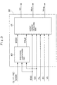
Fig. 2 is a block diagram showing a hydraulic system and an electric system that are applied to the hybrid hydraulic excavator inFig. 1 . -
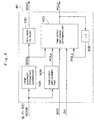
Fig. 3 is a block diagram showing a hybrid control unit inFig. 2 . -
Fig. 4 is a block diagram showing a mode change corresponding part inFig. 3 . -
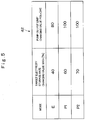
Fig. 5 is an explanatory diagram showing a change value table of a target electricity storage rate and a pump output limit. -
Fig. 6 is a flow chart showing pump output limit change determining processing. -
Fig. 7 is a block diagram showing an output command calculating part inFig. 3 . -
Fig. 8 is an essential part perspective view showing the inside of a cab inFig. 1 . -
Fig. 9 is an explanatory diagram showing an example of a display screen displayed on an in-vehicle monitor. - Hereinafter, a hybrid hydraulic excavator as a hybrid construction machine according to an embodiment in the present invention will be explained as an example with reference to the accompanying drawings.
-
Fig. 1 to Fig. 9 show an embodiment of the present invention. InFig.1 , a hybrid hydraulic excavator 1 (hereinafter, referred to as "hydraulic excavator 1") is provided with anengine 21 and amotor generator 27 to be described later. Thehydraulic excavator 1 includes an automotivelower traveling structure 2 of a crawler type, a revolvingdevice 3 that is provided on thelower traveling structure 2, an upper revolvingstructure 4 that is rotatably mounted on thelower traveling structure 2 through the revolvingdevice 3, and aworking mechanism 11 that is provided in the front side of the upper revolvingstructure 4 and performs an excavating operation of earth and sand and the like. At this time, thelower traveling structure 2 and the upper revolvingstructure 4 configure a vehicle body of thehydraulic excavator 1. - The upper revolving
structure 4 includes ahousing cover 6 that is provided on the revolvingframe 5 to accommodate anengine 21 and the like, and acab 7 for an operator getting in. As shown inFig. 8 , an operator'sseat 8 on which an operator sits is provided in thecab 7, and antraveling operation device 9 that is composed of an operating lever, an operating pedal and the like, and anworking operation device 10 that is composed of an operating lever and the like are provided in the periphery of the operator'sseat 8. Here, theoperation devices operating amount sensors operating amount sensors lower traveling structure 2, a revolving operation of theupper revolving structure 4 or a lifting/tilting operation (excavating operation) of theworking mechanism 11 and the like, for example. Further, an in-vehicle monitor 39 to be described later is provided in thecab 7. - As shown in
Fig. 1 , theworking mechanism 11 is configured of, for example, aboom 11A, anarm 11B, abucket 11C, and aboom cylinder 11D, anarm cylinder 11E and abucket cylinder 11F for driving them. Theboom 11A, thearm 11B and thebucket 11C are pinned to each other. Theworking mechanism 11 is attached to the revolvingframe 5, and extends or contracts thecylinders 11D to 11F to perform a lifting/tilting movement. - Here, the
hydraulic excavator 1 is provided thereon with an electric system that controls amotor generator 27 and the like, and a hydraulic system that controls operations of theworking mechanism 11 and the like. Hereinafter,' an explanation will be made of the system configuration in thehydraulic excavator 1 with reference toFig. 2 to Fig. 9 . - The
engine 21 is mounted on the revolvingframe 5. Theengine 21 is configured of an internal combustion engine such as a diesel engine and the like, for example. Ahydraulic pump 23 and themotor generator 27, which will be described later, are attached mechanically to the output side of theengine 21 for serial connection. Thehydraulic pump 23 and themotor generator 27 are driven by theengine 21. Here, an operation of theengine 21 is controlled by an engine control unit 22 (hereinafter, referred to as "ECU 22"). TheECU 22 controls a rotational speed (engine rotational number) of theengine 21 based upon an engine rotational number command ωe from anHCU 36. The maximum output of theengine 21 is made smaller than the maximum power of thehydraulic pump 23, for example. - The
hydraulic pump 23 is driven by theengine 21. Thehydraulic pump 23 pressurizes hydraulic oil reserved in a tank (not shown), which is supplied to a travelinghydraulic motor 25, a revolvinghydraulic motor 26, thecylinders 11D to 11F of the workingmechanism 11, and the like as pressurized oil. Thehydraulic pump 23 is provided with aload sensor 23A. Theload sensor 23A detects a pump load PL to be outputted to theHCU 36 to be described later. - The
hydraulic pump 23 is connected through acontrol valve 24 to the travelinghydraulic motor 25, the revolvinghydraulic motor 26, and thecylinders 11D to 11F as hydraulic actuators. Thecontrol valve 24 selectively supplies or discharges the pressurized oil supplied from thehydraulic pump 23 to the travelinghydraulic motor 25, the revolvinghydraulic motor 26, and thecylinders 11D to 11F in response to operations to the travelingoperation device 9 and the workingoperation device 10. - Specifically, the pressurized oil is supplied to the traveling
hydraulic motor 25 from thehydraulic pump 23 in response to an operation of the travelingoperation device 9. As a result, the travelinghydraulic motor 25 drives/travels thelower traveling structure 2. The pressurized oil is supplied to the revolvinghydraulic motor 26 from thehydraulic pump 23 in response to an operation of the workingoperation device 10. As a result, the revolvinghydraulic motor 26 operates/revolves the upper revolvingstructure 4. The pressurized oil is supplied to thecylinders 11D to 11F from thehydraulic pump 23 in response to the operation of the workingoperation device 10. As a result, thecylinders 11D to 11F lift/tilt the workingmechanism 11. - The
motor generator 27 is driven by theengine 21. Themotor generator 27 is configured of, for example, a synchronous electric motor and the like. Themotor generator 27 plays two roles of power generation (regeneration) of performing power supply to theelectricity storage device 31 and the revolvingelectric motor 33 by acting as an electric generator by use of theengine 21 as a power source, and power running of assisting in drives of theengine 21 and thehydraulic pump 23 by acting as a motor by use of power from theelectricity storage device 31 and the revolvingelectric motor 33 as a power source. Accordingly, assist torque of themotor generator 27 is added to torque of theengine 21 corresponding to the condition, and thehydraulic pump 23 is driven by the engine torque and the assist torque. An operation of the workingmechanism 11, a travel of the vehicle and the like are performed by the pressurized oil supplied from thehydraulic pump 23. - As shown in
Fig. 2 , themotor generator 27 is connected to a pair ofDC buses first inverter 28. Thefirst inverter 28 is configured by use of a plurality of switching elements such as a transistor and an insulating gate bipolar transistor (IGBT) and the like, for example, and ON/OFF of each of the switching elements is controlled by a motor generator control unit 30 (hereinafter, referred to as "MGCU 30"). TheDC buses - At the power generation of the
motor generator 27, thefirst inverter 28 converts AC power from themotor generator 27 into DC power, which is supplied to theelectricity storage device 31 or the revolvingelectric motor 33. At the power running of themotor generator 27, thefirst inverter 28 converts DC power of theDC buses motor generator 27. TheMGCU 30 controls ON/OFF of each of the switching elements in thefirst inverter 28 based upon a motor generator running/generating power command Wmg from theHUB 36. Thereby, theMGCU 30 controls generator power at the power generation of themotor generator 27 or drive power at the power running of themotor generator 27. - The
electricity storage device 31 is connected electrically to themotor generator 27 through thefirst inverter 28. Theelectricity storage device 31 is configured of, for example, a lithium ion battery and is connected to theDC buses - The
electricity storage device 31 charges power supplied from themotor generator 27 at the power generation of themotor generator 27 and supplies drive power toward themotor generator 27 at the power running (at the assist drive) of themotor generator 27. In addition, theelectricity storage device 31 charges regeneration power supplied from the revolvingelectric motor 33 at the regeneration of the revolvingelectric motor 33 and supplies drive power toward the revolvingelectric motor 33 at the power running of the revolvingelectric motor 33. In this way, theelectricity storage device 31 stores the power generated by themotor generator 27, and further, absorbs the regeneration power generated by the revolvingelectric motor 33 at the revolving braking of thehydraulic excavator 1 to hold the voltage of theDC buses - A charge operation or a discharge operation of the
electricity storage device 31 is controlled by a battery control unit 32 (hereinafter, referred to as "BCU 32"). TheBCU 32 detects a battery electricity storage rate SOC of theelectricity storage device 31 to be outputted to theHCU 36, and controls the charge/discharge of theelectricity storage device 31 such that the battery electricity storage rate SOC becomes a target electricity storage rate SOC0 to be outputted from theHCU 36. - It should be noted that in the present embodiment, a lithium ion battery, for example, having a voltage of 350 V, a discharge capacity of approximately 5 Ah, approximately 30% to 70% of an appropriate use range of the battery electricity storage rate SOC (electricity storage rate) is used in the
electricity storage device 31. The appropriate use range of the battery electricity storage rate SOC and the like are not limited to the above values, but are set as needed in accordance with a specification of theelectricity storage device 31 or the like. - The revolving
electric motor 33 is driven by the power of themotor generator 27 or theelectricity storage device 31. The revolvingelectric motor 33 is configured of a three-phase induction motor, for example, and is provided on the revolvingframe 5 together with the revolvinghydraulic motor 26. The revolvingelectric motor 33 drives the revolvingdevice 3 in cooperation with the revolvinghydraulic motor 26. - As shown in
Fig. 2 , the revolvingelectric motor 33 is connected to theDC buses second inverter 34. The revolvingelectric motor 33 plays two roles of power running of being driven/rotated by receiving power from theelectricity storage device 31 or themotor generator 27, and regeneration of charging theelectricity storage device 31 by generating power with extra torque at the revolving braking. Therefore, the power from themotor generator 27 and the like is supplied through theDC buses electric motor 33 at the power running. Thereby, the revolvingelectric motor 33 generates rotational torque in response to an operation of the workingoperation device 10 to assist in a drive of the revolvinghydraulic motor 26, and drives the revolvingdevice 3 to perform a revolving operation of the upper revolvingstructure 4. - The
second inverter 34 is, as similar to thefirst inverter 28, configured using a plurality of switching elements. ON/OFF of each of the switching elements in thesecond inverter 34 is controlled by a revolving electric motor control unit 35 (hereinafter, referred to as "RMCU 35"). At the power running of the revolvingelectric motor 33, thesecond inverter 34 converts the DC power of theDC buses electric motor 33. At the regeneration of the revolvingelectric motor 33, thesecond inverter 34 converts the AC power from the revolvingelectric motor 33 into DC power to be supplied to theelectricity storage device 31 and the like. - The
RMCU 35 controls ON/OFF of each of the switching elements in thesecond inverter 34 based upon a revolving electric motor running/regenerating power command Wrm from theHCU 36. Thereby, theRMCU 35 controls regeneration power at the regeneration of the revolvingelectric motor 33 and drive power at the power running thereof. - The hybrid control unit (HCU) 36 configures a controller. The
HCU 36 is configured of, for example, a microcomputer, and is connected electrically to theECU 22, theMGCU 30 and theRMCU 35 using a CAN 37 (controller area network) and the like. TheHCU 36 communicates with theECU 22, theMGCU 30 and theRMCU 35, and simultaneously controls theengine 21, themotor generator 27 and the revolvingelectric motor 33. - The
HCU 36 is connected to theoperating amount sensors operation devices load sensor 23A that detects a pump load PL of thehydraulic pump 23. In addition thereto, theHCU 36 is connected to amode selection device 38, the in-vehicle monitor 39 and the like. Thereby, mode information MODE, the battery electricity storage rate SOC, the lever operating amount OA, the pump load PL, engine information EI and various vehicle body information VI are input to theHCU 36. It should be noted that the pump load PL is not necessarily detected directly by theload sensor 23A, but, for example, may be detected indirectly from a pressure (delivery pressure) of hydraulic oil supplied from thehydraulic pump 23. - The
mode selection device 38 is configured of, for example, a switch, a dial, a lever and the like, and selects any one of three kinds of modes composed of an E mode, a P1 mode and a P2 to be described later. Themode selection device 38 is positioned in thecab 7 and is operated by an operator to output the mode information MODE corresponding to the selected mode to theHCU 36. - As shown in
Fig. 8 and Fig. 9 , the in-vehicle monitor 39 is arranged in thecab 7, and displays various pieces of information in regard to the vehicle body such as a remaining amount of fuel, a water temperature of engine cooling water, a working time and an in-compartment temperature. In addition thereto, the in-vehicle monitor 39 is connected to theHCU 36, and is provided with a mode display part 39A. A mode selected from the E mode, the P1 mode and P2 mode by themode selection device 38 is displayed on the mode display part 39A. It should be noted that the in-vehicle monitor 39 may display the mode information MODE (the E mode, the P1 mode or the P2 mode) by connection to themode selection device 38. - The
HCU 36 controls theengine 21, themotor generator 27, and the revolvingelectric motor 33 corresponding to the mode selected by themode selection device 38. Therefore, next an explanation will be made of a specific structure of theHCU 36 with reference toFig. 3 to Fig. 7 . - As shown in
Fig. 3 , theHCU 36 includes a modechange corresponding part 40 and an outputcommand calculating part 41. TheHCU 36 outputs an engine rotational number command ωe, a revolving electric motor running/regenerating power command Wrm and a motor generator running/generating power command Wmg based upon mode information MODE, a battery electricity storage rate SOC, a lever operating amount OA, a pump load PL; engine information EI and various vehicle body information VI. - The mode
change corresponding part 40 calculates a target electricity storage rate SOC0 and a pump output limit POLO based upon the mode information MODE, the battery electricity storage rate SOC and the lever operating amount OA to be outputted. At this time, the target electricity storage rate SOC0 is a target value of the battery electricity storage rate SOC of theelectricity storage device 31. The pump output limit POLO is a limit value of the maximum output in thehydraulic pump 23. - The output
command calculating part 41 calculates an engine rotational number command ωe, a revolving electric motor running/regenerating power command Wrm and a motor generator running/generating power command Wmg based upon the target electricity storage rate SOCO, the pump output limit POLO, the battery electricity storage rate SOC, the lever operating amount OA, the pump load PL, the engine information EI and various vehicle body information VI to be outputted. - Therefore, an explanation will be made of the mode
change corresponding part 40 with reference toFig. 4 to Fig. 6 . The modechange corresponding part 40 determines the target electricity storage rate SOC0 corresponding the mode information MODE, and determines the pump output limit POLO corresponding the mode information MODE, the battery electricity storage rate SOC and the lever operating amount OA. Therefore, the modechange corresponding part 40 receives the mode information MODE by themode selection device 38, the lever operating amount OA by theoperating amount sensor 10A and the battery electricity storage rate SOC transmitted from theBCU 32 as input, and has the target electricity storage rate SOC0 and the pump output limit POLO as output values. The modechange corresponding part 40 includes a target electricity storagerate changing part 40A, a pump outputlimit changing part 40B, a first-order lag filter 40C, a pump output limitchange determining part 40D, and adelay part 40E. - The target electricity storage
rate changing part 40A outputs a target electricity storage rate changing value SOCn. Specifically, the target electricity storagerate changing part 40A selects and outputs a target electricity storage rate changing value SOCn preliminarily set corresponding to the mode (E mode, P1 mode or P2 mode) selected from the input mode information MODE, based upon a changing value table 42 of a target electricity storage rate and a pump output limit shown inFig. 5 . - The pump output
limit changing part 40B outputs a pump output limit changing value POLn. Specifically, the pump outputlimit changing part 40B selects and outputs a pump output limit changing value POLn preliminarily set corresponding to the mode (E mode, P1 mode or P2 mode) selected from the input mode information MODE, based upon the changing value table 42 of the target electricity storage rate and the pump output limit shown inFig. 5 . - Here, the selectable mode includes three kinds of modes of the E mode, the P1 mode and the P2 mode. Among them, the E mode is defined as a mode to be selected in a case where an operator prioritizes fuel consumption over a working amount. As shown in
Fig. 5 , in the E mode, for prioritizing the fuel consumption, the pump output limit changing value POLn is set to a smaller value as compared to the other modes (P1 mode or P2 mode). Accordingly, since it is not necessary for theelectricity storage device 31 to hold so much energy, the target electricity storage rate changing value SOCn is set to a low value (for example, 40%) equal to or less than a half of an appropriate use range (30% to 70%) of the battery electricity storage rate SOC to prioritize the lifetime. - The P1 mode is defined as a mode to be selected in a case where an operator prioritizes a working amount over fuel consumption. In the P1 mode, for prioritizing the working amount, the pump output limit changing value POLn is set to a larger value as compared to the E mode. Accordingly, since it is necessary for the
electricity storage device 31 to hold energy as much as possible, the target electricity storage rate changing value SOCn is set to a high value (for example, 60%) equal to or more than a half of the appropriate use range of the battery electricity storage rate SOC. - Further, the P2 mode is selected at the time of restlessly performing a heavy work, for example, as at a climbing travel and the like, and is defined as a mode to be selected in a case where an operator gives top priority to a continuing force of the work ahead of the lifetime of the
electricity storage device 31. The P2 mode corresponds to a maximum electricity storage rate mode that sets the target electricity storage rate SOC0 to a value close to the maximum value in the appropriate use range of theelectricity storage device 31. - It should be noted that the target electricity storage rate changing value SOCn and the pump output limit changing value POLn of each mode are not limited to those described in
Fig. 5 , but are set as needed corresponding to the specification of thehydraulic excavator 1 and the like. - As shown in
Fig. 4 , the target electricity storage rate changing value SOCn determined by the target electricity storagerate changing part 40A is outputted as the target electricity storage rate SOC0 through the first-order lag filter 40C. At this time, the first-order lag filter 40C has a time constant of approximately several seconds (for example, approximately 3 to 7 seconds). The time constant is set based upon, for example, a time necessary for one operation of each of the revolvingdevice 3 and the workingmechanism 11. Thereby, the target electricity storage rate SOC0 gradually changes from a target electricity storage rate previous value SOCp to a target electricity storage rate changing value SOCn. - At the same time, the target electricity storage rate changing value SOCn outputted from the target electricity storage
rate changing part 40A, the pump output limit changing value POLn outputted from the pump outputlimit changing part 40B and the battery electricity storage rate SOC outputted from theBCU 32 are input to the pump output limitchange determining part 40D, and a pump output limit previous value POLp retained in thedelay part 40E is input thereto. Further, the lever operating amount OA from each of theoperating amount sensors change determining part 40D. The pump output limitchange determining part 40D executes pump output limit change determining processing shown inFig. 6 based upon the inputs. Thereby, the pump output limitchange determining part 40D determines whether to change the pump output limit POLO to the pump output limit changing value POLn or retain the pump output limit POLO to the pump output limit previous value POLp, and outputs the determined pump output limit POLO. - Here, an explanation will be made of the processing at the pump output limit
change determining part 40D with reference toFig. 6 . When the mode is changed, the target electricity storage rate SOCO and the pump output limit POLO are changed at the same time. However, as hereinafter shown, the pump output limit POLO is set to any one of the pump output limit changing value POLn and the pump output limit previous value POLp depending on whether or not the vehicle body is in a non-operating state. - At
step 1, it is determined whether or not the vehicle body is in a non-operating state from a lever operating amount OA. When a determination of "YES" is made atstep 1, since there is no operation of traveling, revolving, lifting/tilting movements of the vehicle body, the process goes to step 2. Atstep 2, a pump output limit POLO is changed to a pump output limit changing value POLn, and the pump output limit POLO is outputted. - On the other hand, when a determination of "NO" is made at
step 1, since an operation of any one of traveling, revolving, lifting/tilting movements of the vehicle body is performed, the process goes to step 3. Atstep 3, the pump output limit POLO is retained to a pump output limit previous value POLp, and the pump output limit POLO is outputted. When steps 2, 3 end, the process returns. - Thereby, the pump output limit
change determining part 40D changes the pump output limit POLO to the pump output limit changing value POLn when the vehicle body is in the non-operating state, and retains the pump output limit POLO to the pump output limit previous value POLp when the vehicle body is in the operating state. - The target electricity storage
rate changing part 40A and the first-order lag filter 40C in the modechange corresponding part 40 configure a target electricity storage rate setting part that sets the target electricity storage rate SOC0 corresponding to the selected mode. In addition, the pump outputlimit changing part 40B and the pump output limitchange determining part 40D in the modechange corresponding part 40 configure a maximum power setting part that increases or decreases the maximum power of thehydraulic pump 23. - Next, an explanation will be made of the output
command calculating part 41 of theHCU 36 with reference toFig. 7 . The outputcommand calculating part 41 calculates an engine rotational number command ωe of theengine 21, a motor generator running/generating power command Wmg of themotor generator 27 and a revolving electric motor running/regenerating power command Wrm of the revolvingelectric motor 33, based upon the target electricity storage rate SOC0 and the pump output limit POLO determined in the modechange corresponding part 40, further, the battery electricity storage rate SOC, the lever operating amount OA, the pump load PL, the engine information EI and various vehicle body information VI to be outputted. The outputcommand calculating part 41 controls theengine 21, themotor generator 27 and the revolvingelectric motor 33 by the commands ωe, Wmg, Wrm such that the battery electricity storage rate SOC approaches the target electricity storage rate SOC0 and the charge or discharge is performed in the vicinity thereof. - An explanation will be made of control processing in a case of controlling a rotational number of the
engine 21 as an example of the outputcommand calculating part 41 with reference toFig. 7 . Hereinafter, a discharge of theelectricity storage device 31 is indicated at plus (+) and a charge thereof is indicated at minus (-), and power running of the electric motor is indicated at plus (+), and power generation and regeneration are indicated at minus (-). - The output
command calculating part 41 includes a target charge/dischargepower calculating part 41A, an engine rotational numbercommand calculating part 41B and an electric motorpower calculating part 41C. The battery electricity storage rate SOC and the target electricity storage rate SOC0 are input to the target charge/dischargepower calculating part 41A. At this time, the target charge/dischargepower calculating part 41A determines target charge/discharge power Wcd such that as an electricity storage rate difference ΔSOC between the battery electricity storage rate SOC and the target electricity storage rate SOC0 is the larger, the electricity storage rate difference ΔSOC is the smaller. Specifically, the target charge/dischargepower calculating part 41A determines and outputs the target charge/discharge power Wcd, for example, such that as a value of the electricity storage rate difference ΔSOC (ΔSOC = SOC - SOC0) and a value of the target charge/discharge power Wcd have a positive correlation. - Next, the target charge/discharge power Wcd and the lever operating amount OA are input to the electric motor
power calculating part 41C. The electric motorpower calculating part 41C determines power running and braking of the revolution by the lever operating amount OA, and outputs the revolving electric motor running/regenerating power command Wrm. Then, the electric motorpower calculating part 41C calculates the motor generator running/generating power command Wmg by a difference between the target charge/discharge power Wcd and the revolving electric motor running/regenerating power command Wrm, and outputs the motor generator running/generating power command Wmg. - Further, the motor generator running/generating power command Wmg, the engine information E1, the pump load PL, and the pump output limit POLO are input to the engine rotational number
command calculating part 41B. When the pump load PL is smaller than the pump output limit POLO, the engine rotational numbercommand calculating part 41B finds engine target output by addition of the pump load PL and the motor generator running/generating power command Wmg. When the pump load PL is larger than the pump output limit POLO, the engine rotational numbercommand calculating part 41B finds engine target output by addition of the pump output limit POLO and the motor generator running/generating power command Wmg. On top of that, the engine rotational numbercommand calculating part 41B calculates the engine rotational number command ωe based upon the engine information E1 such as the present engine rotational number and the like and the engine target output, and outputs the engine rotational number command ωe. - It should be noted that a case where the output
command calculating part 41 calculates the motor generator running/generating power command Wmg, the revolving electric motor running/regenerating power command Wrm and the engine rotational number command ωe based upon the target electricity storage rate SOC0, the pump output limit POLO, the battery electricity storage rate SOC, the lever operating amount OA, the pump load PL and the engine information EI is explained as an example. However, the present invention is not limited thereto, but the outputcommand calculating part 41 may calculate the motor generator running/generating power command Wmg, the revolving electric motor running/regenerating power command Wrm and the engine rotational number command ωe based upon the target electricity storage rate SOC0, the pump output limit POLO, the battery electricity storage rate SOC, the lever operating amount OA, the pump load PL, the engine information EI, and further, various vehicle body information VI such as a vehicle speed, a water cooling temperature and a fuel remaining amount and the like, for example. - The
HCU 36 calculates the motor generator running/generating power command Wmg, the revolving electric motor running/regenerating power command Wrm and the engine rotational number command ωe by the above calculation processing. Then, theHCU 36 outputs the motor generator running/generating power command Wmg to thefirst inverter 28, outputs the revolving electric motor running/regenerating power command Wrm to thesecond inverter 34 and transmits the engine rotational number command ωe to theECU 22. Thereby, theHCU 36 performs realization of an intended vehicle body movement by an operator, and controls of themotor generator 27, the revolvingelectric motor 33 and theengine 21 such that the battery electricity storage rate SOC converges in the target electricity storage rate SOC0 set by the mode. - In this way, according to the present embodiment, the
HCU 36,changes the target electricity storage rate SOCO of theelectricity storage device 31 corresponding to the mode that an operator selects out of the E mode, the P1 mode and the P2 mode by themode selection device 38. Thereby, an operator can actively select priority between the lifetime of theelectricity storage device 31 and the working amount resulting from the stored energy in theelectricity storage device 31. - For example, at a light load, it is possible to lower the target electricity storage rate SOC0 by selecting the E mode. Therefore, the
electricity storage device 31 repeats the charge/discharge in a state where the battery electricity storage rate SOC is low to suppress a degradation of theelectricity storage device 31, making it possible to extend the lifetime of theelectricity storage device 31. On the other hand, at a heavy load, it is possible to increase the target electricity storage rate SOC0 by selecting the P1 mode or the P2 mode. Thereby, since it is possible to reserve large energy in theelectricity storage device 31, power supply to themotor generator 27 is performed for longer hours, making it possible to assist in theengine 21 by power running of themotor generator 27, that is, perform the movement of the vehicle body according to a demand of an operator. - The
HCU 36 sets the pump output limit POLO in the E mode low in the target electricity storage rate SOC0 to be smaller than in the P1 mode or the P2 mode high in the target electricity storage rate SOC0. Thereby, even in the E mode in which the lifetime takes priority, it is possible to limit the maximum output of thehydraulic pump 23 to be a smaller value as compared to the P1 mode or the P2 mode. As a result, for example, since the discharge energy amount of theelectricity storage device 31 by the power running of themotor generator 27 or the revolvingelectric motor 33 can be made small, it is possible to prevent an energy shortage (power shortage) of theelectricity storage device 31. - Since the first-
order lag filter 40C is provided in the output side of the target electricity storagerate changing part 40A, the modechange corresponding part 40 of theHCU 36 gradually changes the target electricity storage rate SOC0 from the target electricity storage rate previous value SOCp to the target electricity storage rate changing value SOCn time-sequentially. Thereby, since it is possible to prevent an abrupt change of the battery electricity storage rate SOC by the mode change, an unexpected vehicle body movement can be prevented. - In addition thereto, the mode
change corresponding part 40 of theHCU 36 changes the pump output limit POLO when the mode is changed by themode selection device 38 and the vehicle body becomes in the non-operating state. Therefore, the maximum power of thehydraulic pump 23 is not changed in the halfway of the operating of the vehicle body such as in the halfway of the traveling of thelower traveling structure 2, in the halfway of the revolving of the upper revolvingstructure 4 and in the halfway of the excavating operation of the workingmechanism 11 and the like, for example, and it is possible to change the maximum power of thehydraulic pump 23 in a stop state of the vehicle body. As a result, even at the time of changing the mode, an unexpected vehicle body movement can be prevented. - The
mode selection device 38 can select the P2 mode in which the target electricity storage rate SOC0 is set to the vicinity of the maximum use range of an appropriate battery electricity storage rate SOC. Thereby, even at the time of restlessly performing a heavy load work such as at the climbing travel and the like, for example, top priority can be given to a work continuing force by selection of the P2 mode by an operator, and it is possible to continue the vehicle body movement for a long time as much as possible. - Further, since there is provided the in-
vehicle monitor 39 that displays the mode selected by themode selection device 38, an operator can easily recognize the mode selected at present by visual contact with the in-vehicle monitor 39. Therefore, since it is possible to easily compare a work demanded by an operator with the present mode, the mode can be quickly changed in a case where both of them are different from each other. - Since the maximum output of the
engine 21 is made smaller than the maximum power of thehydraulic pump 23, it is possible to use theengine 21 that is small in size and is capable of reducing fuel consumption. On the other hand, since the maximum output of theengine 21 is made smaller than the maximum power of thehydraulic pump 23, as compared to a case where the engine output is sufficiently larger than the maximum pump load, a contribution percentage of the engine assist by power running of themotor generator 27 at the vehicle body movement is larger and there is a tendency that the frequency at which theelectricity storage device 31 repeats the charge/discharge becomes high. In contrast, in the present embodiment, the target electricity storage rate SOC0 can be set to a low value by selecting the E mode. As a result, as compared to a case where the target electricity storage rate SOC0 is set to a high value, a degradation of theelectricity storage device 31 can be suppressed. - It should be noted that in the above embodiment, the
mode selection device 38 can select the three kinds of modes (E mode, P1 mode, P2 mode) in which the different target electricity storage rate SOCO and the different pump output limit POLO are set. However, the present invention is not limited thereto, but a mode selection device may select four kinds of modes or more, and a target electricity storage rate or a pump output limit may be controlled more finely according to these modes. The mode selection device may select a fourth mode in which a target electricity storage rate and a pump output limit intermediate between the E mode and the P1 mode are set. Further, the mode selection device may select two kinds of modes by excluding any one of the P1 mode and the P2 mode. - The mode
change corresponding part 40 in the above embodiment gradually changes the target electricity storage rate SOC0 from the target electricity storage rate previous value SOCp to the target electricity storage rate changing value SOCn by the first-order lag filter 40C. However, the present invention is not limited thereto, but it is only required to gradually change the target electricity storage rate SOC0 time-sequentially, and, for example, the target electricity storage rate SOC0 may be changed proportionally from the target electricity storage rate previous value SOCp to the target electricity storage rate changing value SOCn in a predetermined transitional time. - In the above embodiment, the maximum output of the
engine 21 is made smaller than the maximum power of thehydraulic pump 23, but the maximum output of theengine 21 is appropriately set corresponding to a specification of thehydraulic excavator 1 or the like. Therefore, the maximum output of theengine 21 may be approximately close to the maximum power of thehydraulic pump 23, or may be smaller than the maximum power of thehydraulic pump 23. - In the above embodiment, an example of using the lithium ion battery in the
electricity storage device 31 is explained, but a secondary battery (for example, nickel cadmium battery or nickel hydrogen battery) or a capacitor that can supply necessary power may be adopted. In addition, a voltage increase-reduce device such as a DC-DC converter may be provided between an electricity storage device and a DC bus. - In the above embodiment, the rotational number of the
engine 21 is limited corresponding to the pump output limit POLO, but, for example, in a case of using a variable capacity hydraulic pump, a delivery capacity of the hydraulic pump may be changed corresponding to the pump output limit POLO. - The above embodiment is provided with the revolving
hydraulic motor 26 and the revolvingelectric motor 33. However, the present invention is not limited thereto, but, for example, it may be configured that any one of the revolvinghydraulic motor 26 and the revolvingelectric motor 33 may be eliminated. - In the above embodiment, an example of using the
hydraulic excavator 1 of a crawler type as the hybrid construction machine is explained. However, the present invention is not limited thereto, but the present invention may be applied to a hybrid construction machine that is provided with a motor generator jointed to an engine and a hydraulic pump, and an electricity storage device, and for example, may be applied to various types of construction machines such as a wheel type hybrid hydraulic excavator, a hybrid wheel loader or a hybrid dump truck and the like. -
- 1: Hybrid-type hydraulic excavator
- 2: Lower traveling structure (Vehicle body)
- 4: Upper revolving structure (Vehicle body)
- 9: Traveling operation device
- 9A, 10A: Operating amount sensor (Vehicle body operating state detecting device)
- 10: Working operation device
- 11: Working mechanism
- 11D: Boom cylinder (Hydraulic actuator)
- 11E: Arm cylinder (Hydraulic actuator)
- 11F: Bucket cylinder (Hydraulic actuator)
- 21: Engine
- 23: Hydraulic pump
- 25: Traveling hydraulic motor (Hydraulic actuator)
- 26: Revolving hydraulic motor (Hydraulic actuator)
- 27: Motor generator
- 31: Electricity storage device
- 33: Revolving electric motor
- 36: Hybrid control unit (Controller)
- 38: Mode selection device
- 39: In-vehicle monitor
- 40: Mode change corresponding part
- 40A: Target electricity storage rate changing part
- 40B: Pump output limit changing part
- 40C: First-order lag filter
- 40D: Pump output limit change determining part
- 40E: Delay part
- 41: Output command calculating part
Claims (7)
- A hybrid construction machine comprising:an engine that is provided on a vehicle body;a hydraulic pump that is connected mechanically to said engine;a hydraulic actuator that is driven by pressurized oil from said hydraulic pump;a motor generator that is connected mechanically to said engine;an electricity storage device that is connected electrically to said motor generator; anda controller that controls charge/discharge power of said motor generator and said electricity storage device,characterized in that:a mode selection device that selects any one of a plurality of modes in which target electricity storage rates differing from each other are set is further provided, andsaid controller controls the charge/discharge power of said motor generator and said electricity storage device such that an electricity storage rate of said electricity storage device converges with a target electricity storage rate of the mode selected by said mode selection device.
- The hybrid construction machine according to claim 1, wherein
said controller includes a maximum power setting part that increases or decreases maximum power of said hydraulic pump, wherein
said maximum power setting part limits the maximum power of said hydraulic pump to a smaller value according to the lowering of the target electricity storage rate of the mode selected by said mode selection device. - The hybrid construction machine according to claim 1, wherein
said controller continuously and gradually changes a value of the target electricity storage rate from a value before mode change to a value after mode change when the mode is changed by said mode selection device. - The hybrid construction machine according to claim 2, further comprising:a vehicle body operating state detecting device that detects an operating state of said vehicle body, whereinsaid maximum power setting part changes the maximum power of said hydraulic pump when the mode is changed by said mode selection device and a non-operating state of said vehicle body is detected by said vehicle body operating state detecting device.
- The hybrid construction machine according to claim 2, wherein
said mode selection device does not limit the maximum power of said hydraulic pump and can select a maximum electricity storage rate mode in which the target electricity storage rate is set in the vicinity of the maximum electricity storage rate of said electricity storage device. - The hybrid construction machine according to claim 1, further comprising:an in-vehicle monitor that displays the mode selected by said mode selection device.
- The hybrid construction machine according to claim 1, wherein
maximum output of said engine is made smaller than the maximum power of said hydraulic pump.
Applications Claiming Priority (2)
| Application Number | Priority Date | Filing Date | Title |
|---|---|---|---|
| JP2015010340A JP6243856B2 (en) | 2015-01-22 | 2015-01-22 | Hybrid construction machinery |
| PCT/JP2015/084374 WO2016117232A1 (en) | 2015-01-22 | 2015-12-08 | Hybrid construction machine |
Publications (3)
| Publication Number | Publication Date |
|---|---|
| EP3249115A1 true EP3249115A1 (en) | 2017-11-29 |
| EP3249115A4 EP3249115A4 (en) | 2018-09-19 |
| EP3249115B1 EP3249115B1 (en) | 2022-04-06 |
Family
ID=56416792
Family Applications (1)
| Application Number | Title | Priority Date | Filing Date |
|---|---|---|---|
| EP15878921.4A Active EP3249115B1 (en) | 2015-01-22 | 2015-12-08 | Hybrid construction machine |
Country Status (6)
| Country | Link |
|---|---|
| US (1) | US10150465B2 (en) |
| EP (1) | EP3249115B1 (en) |
| JP (1) | JP6243856B2 (en) |
| KR (1) | KR101981406B1 (en) |
| CN (1) | CN106605028B (en) |
| WO (1) | WO2016117232A1 (en) |
Families Citing this family (3)
| Publication number | Priority date | Publication date | Assignee | Title |
|---|---|---|---|---|
| JP6695231B2 (en) * | 2016-07-28 | 2020-05-20 | 日立建機株式会社 | Hybrid construction machinery |
| JP7388954B2 (en) * | 2020-03-11 | 2023-11-29 | 株式会社小松製作所 | Operation guide device |
| CN115259011A (en) * | 2022-07-26 | 2022-11-01 | 中建八局第二建设有限公司 | Building electromechanical comprehensive pipeline lifting vehicle and operation method |
Family Cites Families (7)
| Publication number | Priority date | Publication date | Assignee | Title |
|---|---|---|---|---|
| JP4867665B2 (en) | 2007-01-16 | 2012-02-01 | 株式会社明電舎 | Charge / discharge control device for power storage unit |
| JP5314906B2 (en) * | 2008-02-29 | 2013-10-16 | ニチユ三菱フォークリフト株式会社 | Work vehicle control method and work vehicle |
| JP2012082644A (en) | 2010-10-14 | 2012-04-26 | Hitachi Constr Mach Co Ltd | Construction machine |
| JP5585487B2 (en) | 2011-02-17 | 2014-09-10 | コベルコ建機株式会社 | Power source device for hybrid construction machinery |
| JP5959874B2 (en) * | 2012-02-15 | 2016-08-02 | 日立建機株式会社 | Hybrid work vehicle |
| JP6162969B2 (en) * | 2013-02-04 | 2017-07-12 | 日立建機株式会社 | Work machine |
| CN203924155U (en) * | 2014-06-06 | 2014-11-05 | 山东中川液压有限公司 | High-efficient energy-saving environment friendly oil-liquid hybrid electric excavator |
-
2015
- 2015-01-22 JP JP2015010340A patent/JP6243856B2/en active Active
- 2015-12-08 KR KR1020177005663A patent/KR101981406B1/en active IP Right Grant
- 2015-12-08 WO PCT/JP2015/084374 patent/WO2016117232A1/en active Application Filing
- 2015-12-08 US US15/508,552 patent/US10150465B2/en active Active
- 2015-12-08 EP EP15878921.4A patent/EP3249115B1/en active Active
- 2015-12-08 CN CN201580047735.2A patent/CN106605028B/en active Active
Also Published As
| Publication number | Publication date |
|---|---|
| JP2016132968A (en) | 2016-07-25 |
| EP3249115A4 (en) | 2018-09-19 |
| JP6243856B2 (en) | 2017-12-06 |
| US10150465B2 (en) | 2018-12-11 |
| CN106605028A (en) | 2017-04-26 |
| KR20170037657A (en) | 2017-04-04 |
| CN106605028B (en) | 2020-02-18 |
| US20170274891A1 (en) | 2017-09-28 |
| WO2016117232A1 (en) | 2016-07-28 |
| KR101981406B1 (en) | 2019-05-22 |
| EP3249115B1 (en) | 2022-04-06 |
Similar Documents
| Publication | Publication Date | Title |
|---|---|---|
| KR101539167B1 (en) | Hybrid working machine and method of controlling hybrid working machine | |
| JP5225779B2 (en) | Charge / discharge control method | |
| KR101714948B1 (en) | Construction machine | |
| KR20150069025A (en) | Hybrid work machine | |
| JP6592187B2 (en) | Hybrid construction machinery | |
| US11001154B2 (en) | Hybrid construction machine | |
| WO2016088827A1 (en) | Construction machine | |
| KR20150076245A (en) | Hybrid work machine | |
| US10150465B2 (en) | Hybrid construction machine | |
| US10364549B2 (en) | Hybrid construction machine | |
| EP3342940B1 (en) | Hybrid construction machine | |
| JP6578216B2 (en) | Hybrid construction machine | |
| JP6640650B2 (en) | Construction machinery | |
| CN104781118A (en) | Hybrid shovel and hybrid shovel control method |
Legal Events
| Date | Code | Title | Description |
|---|---|---|---|
| STAA | Information on the status of an ep patent application or granted ep patent |
Free format text: STATUS: THE INTERNATIONAL PUBLICATION HAS BEEN MADE |
|
| PUAI | Public reference made under article 153(3) epc to a published international application that has entered the european phase |
Free format text: ORIGINAL CODE: 0009012 |
|
| STAA | Information on the status of an ep patent application or granted ep patent |
Free format text: STATUS: REQUEST FOR EXAMINATION WAS MADE |
|
| 17P | Request for examination filed |
Effective date: 20170822 |
|
| AK | Designated contracting states |
Kind code of ref document: A1 Designated state(s): AL AT BE BG CH CY CZ DE DK EE ES FI FR GB GR HR HU IE IS IT LI LT LU LV MC MK MT NL NO PL PT RO RS SE SI SK SM TR |
|
| AX | Request for extension of the european patent |
Extension state: BA ME |
|
| DAV | Request for validation of the european patent (deleted) | ||
| DAX | Request for extension of the european patent (deleted) | ||
| A4 | Supplementary search report drawn up and despatched |
Effective date: 20180820 |
|
| RIC1 | Information provided on ipc code assigned before grant |
Ipc: E02F 9/20 20060101AFI20180813BHEP |
|
| GRAP | Despatch of communication of intention to grant a patent |
Free format text: ORIGINAL CODE: EPIDOSNIGR1 |
|
| STAA | Information on the status of an ep patent application or granted ep patent |
Free format text: STATUS: GRANT OF PATENT IS INTENDED |
|
| RIC1 | Information provided on ipc code assigned before grant |
Ipc: E02F 9/22 20060101ALI20211129BHEP Ipc: E02F 9/12 20060101ALI20211129BHEP Ipc: E02F 9/20 20060101AFI20211129BHEP |
|
| INTG | Intention to grant announced |
Effective date: 20211216 |
|
| GRAS | Grant fee paid |
Free format text: ORIGINAL CODE: EPIDOSNIGR3 |
|
| GRAA | (expected) grant |
Free format text: ORIGINAL CODE: 0009210 |
|
| STAA | Information on the status of an ep patent application or granted ep patent |
Free format text: STATUS: THE PATENT HAS BEEN GRANTED |
|
| AK | Designated contracting states |
Kind code of ref document: B1 Designated state(s): AL AT BE BG CH CY CZ DE DK EE ES FI FR GB GR HR HU IE IS IT LI LT LU LV MC MK MT NL NO PL PT RO RS SE SI SK SM TR |
|
| REG | Reference to a national code |
Ref country code: GB Ref legal event code: FG4D |
|
| REG | Reference to a national code |
Ref country code: CH Ref legal event code: EP |
|
| REG | Reference to a national code |
Ref country code: AT Ref legal event code: REF Ref document number: 1481454 Country of ref document: AT Kind code of ref document: T Effective date: 20220415 |
|
| REG | Reference to a national code |
Ref country code: DE Ref legal event code: R096 Ref document number: 602015078122 Country of ref document: DE |
|
| REG | Reference to a national code |
Ref country code: IE Ref legal event code: FG4D |
|
| REG | Reference to a national code |
Ref country code: LT Ref legal event code: MG9D |
|
| REG | Reference to a national code |
Ref country code: NL Ref legal event code: MP Effective date: 20220406 |
|
| REG | Reference to a national code |
Ref country code: AT Ref legal event code: MK05 Ref document number: 1481454 Country of ref document: AT Kind code of ref document: T Effective date: 20220406 |
|
| PG25 | Lapsed in a contracting state [announced via postgrant information from national office to epo] |
Ref country code: NL Free format text: LAPSE BECAUSE OF FAILURE TO SUBMIT A TRANSLATION OF THE DESCRIPTION OR TO PAY THE FEE WITHIN THE PRESCRIBED TIME-LIMIT Effective date: 20220406 |
|
| PG25 | Lapsed in a contracting state [announced via postgrant information from national office to epo] |
Ref country code: SE Free format text: LAPSE BECAUSE OF FAILURE TO SUBMIT A TRANSLATION OF THE DESCRIPTION OR TO PAY THE FEE WITHIN THE PRESCRIBED TIME-LIMIT Effective date: 20220406 Ref country code: PT Free format text: LAPSE BECAUSE OF FAILURE TO SUBMIT A TRANSLATION OF THE DESCRIPTION OR TO PAY THE FEE WITHIN THE PRESCRIBED TIME-LIMIT Effective date: 20220808 Ref country code: NO Free format text: LAPSE BECAUSE OF FAILURE TO SUBMIT A TRANSLATION OF THE DESCRIPTION OR TO PAY THE FEE WITHIN THE PRESCRIBED TIME-LIMIT Effective date: 20220706 Ref country code: LT Free format text: LAPSE BECAUSE OF FAILURE TO SUBMIT A TRANSLATION OF THE DESCRIPTION OR TO PAY THE FEE WITHIN THE PRESCRIBED TIME-LIMIT Effective date: 20220406 Ref country code: HR Free format text: LAPSE BECAUSE OF FAILURE TO SUBMIT A TRANSLATION OF THE DESCRIPTION OR TO PAY THE FEE WITHIN THE PRESCRIBED TIME-LIMIT Effective date: 20220406 Ref country code: GR Free format text: LAPSE BECAUSE OF FAILURE TO SUBMIT A TRANSLATION OF THE DESCRIPTION OR TO PAY THE FEE WITHIN THE PRESCRIBED TIME-LIMIT Effective date: 20220707 Ref country code: FI Free format text: LAPSE BECAUSE OF FAILURE TO SUBMIT A TRANSLATION OF THE DESCRIPTION OR TO PAY THE FEE WITHIN THE PRESCRIBED TIME-LIMIT Effective date: 20220406 Ref country code: ES Free format text: LAPSE BECAUSE OF FAILURE TO SUBMIT A TRANSLATION OF THE DESCRIPTION OR TO PAY THE FEE WITHIN THE PRESCRIBED TIME-LIMIT Effective date: 20220406 Ref country code: BG Free format text: LAPSE BECAUSE OF FAILURE TO SUBMIT A TRANSLATION OF THE DESCRIPTION OR TO PAY THE FEE WITHIN THE PRESCRIBED TIME-LIMIT Effective date: 20220706 Ref country code: AT Free format text: LAPSE BECAUSE OF FAILURE TO SUBMIT A TRANSLATION OF THE DESCRIPTION OR TO PAY THE FEE WITHIN THE PRESCRIBED TIME-LIMIT Effective date: 20220406 |
|
| PG25 | Lapsed in a contracting state [announced via postgrant information from national office to epo] |
Ref country code: RS Free format text: LAPSE BECAUSE OF FAILURE TO SUBMIT A TRANSLATION OF THE DESCRIPTION OR TO PAY THE FEE WITHIN THE PRESCRIBED TIME-LIMIT Effective date: 20220406 Ref country code: PL Free format text: LAPSE BECAUSE OF FAILURE TO SUBMIT A TRANSLATION OF THE DESCRIPTION OR TO PAY THE FEE WITHIN THE PRESCRIBED TIME-LIMIT Effective date: 20220406 Ref country code: LV Free format text: LAPSE BECAUSE OF FAILURE TO SUBMIT A TRANSLATION OF THE DESCRIPTION OR TO PAY THE FEE WITHIN THE PRESCRIBED TIME-LIMIT Effective date: 20220406 Ref country code: IS Free format text: LAPSE BECAUSE OF FAILURE TO SUBMIT A TRANSLATION OF THE DESCRIPTION OR TO PAY THE FEE WITHIN THE PRESCRIBED TIME-LIMIT Effective date: 20220806 |
|
| REG | Reference to a national code |
Ref country code: DE Ref legal event code: R097 Ref document number: 602015078122 Country of ref document: DE |
|
| PG25 | Lapsed in a contracting state [announced via postgrant information from national office to epo] |
Ref country code: SM Free format text: LAPSE BECAUSE OF FAILURE TO SUBMIT A TRANSLATION OF THE DESCRIPTION OR TO PAY THE FEE WITHIN THE PRESCRIBED TIME-LIMIT Effective date: 20220406 Ref country code: SK Free format text: LAPSE BECAUSE OF FAILURE TO SUBMIT A TRANSLATION OF THE DESCRIPTION OR TO PAY THE FEE WITHIN THE PRESCRIBED TIME-LIMIT Effective date: 20220406 Ref country code: RO Free format text: LAPSE BECAUSE OF FAILURE TO SUBMIT A TRANSLATION OF THE DESCRIPTION OR TO PAY THE FEE WITHIN THE PRESCRIBED TIME-LIMIT Effective date: 20220406 Ref country code: EE Free format text: LAPSE BECAUSE OF FAILURE TO SUBMIT A TRANSLATION OF THE DESCRIPTION OR TO PAY THE FEE WITHIN THE PRESCRIBED TIME-LIMIT Effective date: 20220406 Ref country code: DK Free format text: LAPSE BECAUSE OF FAILURE TO SUBMIT A TRANSLATION OF THE DESCRIPTION OR TO PAY THE FEE WITHIN THE PRESCRIBED TIME-LIMIT Effective date: 20220406 Ref country code: CZ Free format text: LAPSE BECAUSE OF FAILURE TO SUBMIT A TRANSLATION OF THE DESCRIPTION OR TO PAY THE FEE WITHIN THE PRESCRIBED TIME-LIMIT Effective date: 20220406 |
|
| PLBE | No opposition filed within time limit |
Free format text: ORIGINAL CODE: 0009261 |
|
| STAA | Information on the status of an ep patent application or granted ep patent |
Free format text: STATUS: NO OPPOSITION FILED WITHIN TIME LIMIT |
|
| 26N | No opposition filed |
Effective date: 20230110 |
|
| PG25 | Lapsed in a contracting state [announced via postgrant information from national office to epo] |
Ref country code: AL Free format text: LAPSE BECAUSE OF FAILURE TO SUBMIT A TRANSLATION OF THE DESCRIPTION OR TO PAY THE FEE WITHIN THE PRESCRIBED TIME-LIMIT Effective date: 20220406 |
|
| PG25 | Lapsed in a contracting state [announced via postgrant information from national office to epo] |
Ref country code: SI Free format text: LAPSE BECAUSE OF FAILURE TO SUBMIT A TRANSLATION OF THE DESCRIPTION OR TO PAY THE FEE WITHIN THE PRESCRIBED TIME-LIMIT Effective date: 20220406 |
|
| REG | Reference to a national code |
Ref country code: CH Ref legal event code: PL |
|
| REG | Reference to a national code |
Ref country code: BE Ref legal event code: MM Effective date: 20221231 |
|
| PG25 | Lapsed in a contracting state [announced via postgrant information from national office to epo] |
Ref country code: LU Free format text: LAPSE BECAUSE OF NON-PAYMENT OF DUE FEES Effective date: 20221208 |
|
| PG25 | Lapsed in a contracting state [announced via postgrant information from national office to epo] |
Ref country code: LI Free format text: LAPSE BECAUSE OF NON-PAYMENT OF DUE FEES Effective date: 20221231 Ref country code: IE Free format text: LAPSE BECAUSE OF NON-PAYMENT OF DUE FEES Effective date: 20221208 Ref country code: CH Free format text: LAPSE BECAUSE OF NON-PAYMENT OF DUE FEES Effective date: 20221231 |
|
| PG25 | Lapsed in a contracting state [announced via postgrant information from national office to epo] |
Ref country code: FR Free format text: LAPSE BECAUSE OF NON-PAYMENT OF DUE FEES Effective date: 20221231 Ref country code: BE Free format text: LAPSE BECAUSE OF NON-PAYMENT OF DUE FEES Effective date: 20221231 |
|
| PGFP | Annual fee paid to national office [announced via postgrant information from national office to epo] |
Ref country code: GB Payment date: 20231102 Year of fee payment: 9 |
|
| PG25 | Lapsed in a contracting state [announced via postgrant information from national office to epo] |
Ref country code: IT Free format text: LAPSE BECAUSE OF FAILURE TO SUBMIT A TRANSLATION OF THE DESCRIPTION OR TO PAY THE FEE WITHIN THE PRESCRIBED TIME-LIMIT Effective date: 20220406 |
|
| PGFP | Annual fee paid to national office [announced via postgrant information from national office to epo] |
Ref country code: DE Payment date: 20231031 Year of fee payment: 9 |
|
| PG25 | Lapsed in a contracting state [announced via postgrant information from national office to epo] |
Ref country code: HU Free format text: LAPSE BECAUSE OF FAILURE TO SUBMIT A TRANSLATION OF THE DESCRIPTION OR TO PAY THE FEE WITHIN THE PRESCRIBED TIME-LIMIT; INVALID AB INITIO Effective date: 20151208 |