EP3248655A1 - Fire suppression container and methods for suppressing a fire with an object within the container - Google Patents
Fire suppression container and methods for suppressing a fire with an object within the container Download PDFInfo
- Publication number
- EP3248655A1 EP3248655A1 EP17172933.8A EP17172933A EP3248655A1 EP 3248655 A1 EP3248655 A1 EP 3248655A1 EP 17172933 A EP17172933 A EP 17172933A EP 3248655 A1 EP3248655 A1 EP 3248655A1
- Authority
- EP
- European Patent Office
- Prior art keywords
- base
- fire
- internal area
- lid
- sleeve
- Prior art date
- Legal status (The legal status is an assumption and is not a legal conclusion. Google has not performed a legal analysis and makes no representation as to the accuracy of the status listed.)
- Granted
Links
Images



Classifications
-
- A—HUMAN NECESSITIES
- A62—LIFE-SAVING; FIRE-FIGHTING
- A62C—FIRE-FIGHTING
- A62C3/00—Fire prevention, containment or extinguishing specially adapted for particular objects or places
- A62C3/07—Fire prevention, containment or extinguishing specially adapted for particular objects or places in vehicles, e.g. in road vehicles
- A62C3/08—Fire prevention, containment or extinguishing specially adapted for particular objects or places in vehicles, e.g. in road vehicles in aircraft
-
- A—HUMAN NECESSITIES
- A62—LIFE-SAVING; FIRE-FIGHTING
- A62C—FIRE-FIGHTING
- A62C3/00—Fire prevention, containment or extinguishing specially adapted for particular objects or places
- A62C3/06—Fire prevention, containment or extinguishing specially adapted for particular objects or places of highly inflammable material, e.g. light metals, petroleum products
-
- A—HUMAN NECESSITIES
- A62—LIFE-SAVING; FIRE-FIGHTING
- A62C—FIRE-FIGHTING
- A62C35/00—Permanently-installed equipment
- A62C35/02—Permanently-installed equipment with containers for delivering the extinguishing substance
-
- A—HUMAN NECESSITIES
- A62—LIFE-SAVING; FIRE-FIGHTING
- A62C—FIRE-FIGHTING
- A62C99/00—Subject matter not provided for in other groups of this subclass
- A62C99/0009—Methods of extinguishing or preventing the spread of fire by cooling down or suffocating the flames
-
- H—ELECTRICITY
- H01—ELECTRIC ELEMENTS
- H01M—PROCESSES OR MEANS, e.g. BATTERIES, FOR THE DIRECT CONVERSION OF CHEMICAL ENERGY INTO ELECTRICAL ENERGY
- H01M10/00—Secondary cells; Manufacture thereof
- H01M10/02—Details
-
- H—ELECTRICITY
- H01—ELECTRIC ELEMENTS
- H01M—PROCESSES OR MEANS, e.g. BATTERIES, FOR THE DIRECT CONVERSION OF CHEMICAL ENERGY INTO ELECTRICAL ENERGY
- H01M10/00—Secondary cells; Manufacture thereof
- H01M10/05—Accumulators with non-aqueous electrolyte
- H01M10/052—Li-accumulators
- H01M10/0525—Rocking-chair batteries, i.e. batteries with lithium insertion or intercalation in both electrodes; Lithium-ion batteries
-
- H—ELECTRICITY
- H01—ELECTRIC ELEMENTS
- H01M—PROCESSES OR MEANS, e.g. BATTERIES, FOR THE DIRECT CONVERSION OF CHEMICAL ENERGY INTO ELECTRICAL ENERGY
- H01M2200/00—Safety devices for primary or secondary batteries
-
- Y—GENERAL TAGGING OF NEW TECHNOLOGICAL DEVELOPMENTS; GENERAL TAGGING OF CROSS-SECTIONAL TECHNOLOGIES SPANNING OVER SEVERAL SECTIONS OF THE IPC; TECHNICAL SUBJECTS COVERED BY FORMER USPC CROSS-REFERENCE ART COLLECTIONS [XRACs] AND DIGESTS
- Y02—TECHNOLOGIES OR APPLICATIONS FOR MITIGATION OR ADAPTATION AGAINST CLIMATE CHANGE
- Y02E—REDUCTION OF GREENHOUSE GAS [GHG] EMISSIONS, RELATED TO ENERGY GENERATION, TRANSMISSION OR DISTRIBUTION
- Y02E60/00—Enabling technologies; Technologies with a potential or indirect contribution to GHG emissions mitigation
- Y02E60/10—Energy storage using batteries
Definitions
- the present disclosure generally relates to a fire suppression apparatus for containing, suppressing, and extinguishing a fire of an object, and more particularly to extinguishing a fire of an object caused by a lithium battery exhibiting thermal runaway.
- Devices exist for attempting to suppress fires and in particular electrical or chemical fires in which water or typical fire extinguishers are insufficient, that include a volume sufficient to contain the electrical device and a covers for containing the fire within the device preventing spread of the fire.
- many of existing devices do not contemplate a thermal runaway reaction or a resulting fire that will continue, but rather are focused on isolating the dangerous condition.
- What is needed is a method for handling a fire, such as a consumer electronics lithium ion battery fire, in a cabin of an aircraft during flight.
- a fire such as a consumer electronics lithium ion battery fire
- a fire suppression apparatus comprising a base that has an opening.
- the base comprises walls defining an internal area, and a sleeve with a portion positioned in the internal area and around a perimeter of the walls.
- the sleeve defines a region of the internal area for placing an object, and the sleeve has an opening for placing the object into the region.
- the base further comprises a first fire suppressing powder positioned in the internal area between the sleeve and the walls.
- the fire suppression apparatus also comprise a lid for covering the opening of the base.
- the lid comprises a cavity, a second fire suppressing powder contained inside the cavity, and a divider positioned to cover the cavity of the lid.
- a method for suppressing a fire of an object comprises placing the object into a region of an internal area of a base defined by a sleeve.
- the base has an opening and walls defining the internal area, and the base includes the sleeve with a portion positioned in the internal area and around a perimeter of the walls that defines the region of the internal area for placing the object.
- the base further comprises a first fire suppressing powder positioned in the internal area between the sleeve and the walls.
- the method also comprises removing the sleeve from the base causing the first fire suppressing powder to collapse on a portion of the region of the internal area for placing the object, and covering the opening of the base with a lid.
- the lid has a cavity and a second fire suppressing powder contained inside the cavity, and the lid comprises a divider positioned to cover the cavity of the lid.
- the method also comprises removing the divider from the lid to release the second fire suppressing powder into the internal area of the base.
- another method for suppressing a fire of an object comprises positioning a first fire suppressing powder in an internal area of a base that has an opening and walls defining the internal area, and the base includes a sleeve in the internal area and around a perimeter of the walls that defines a region of the internal area for placing an object.
- the method also comprises collapsing the first fire suppressing powder on a portion of the region of the internal area for placing the object by removal of the sleeve and covering the opening of the base with a lid.
- the lid has a cavity and a second fire suppressing powder contained inside the cavity.
- the method also comprises releasing the second fire suppressing powder into the internal area of the base.
- a fire suppression, containment, and extinguishing apparatus is described.
- the apparatus may be useful for an aircraft passenger battery fire suppression system to handle lithium battery fires in a cabin of an aircraft carrying passengers to improve safety of passengers on board.
- a base including a fire suppressing powder is used, for example, to engulf a burning consumer electronics device containing lithium ion batteries in flight.
- methods of scrubbing exhaust gasses are described to help prevent noxious fumes from entering the cabin. Additional venting methods are described to vent to an existing aircraft exhaust vent system.
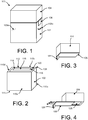
- the apparatus 100 includes a base 102, a lid 104, and a divider 106.
- the lid 104 covers an opening 108 of the base 102.
- the apparatus 100 is a portable container.
- the apparatus 100 may include handles 105a-b on either side of the base 102 for carrying the apparatus 100.
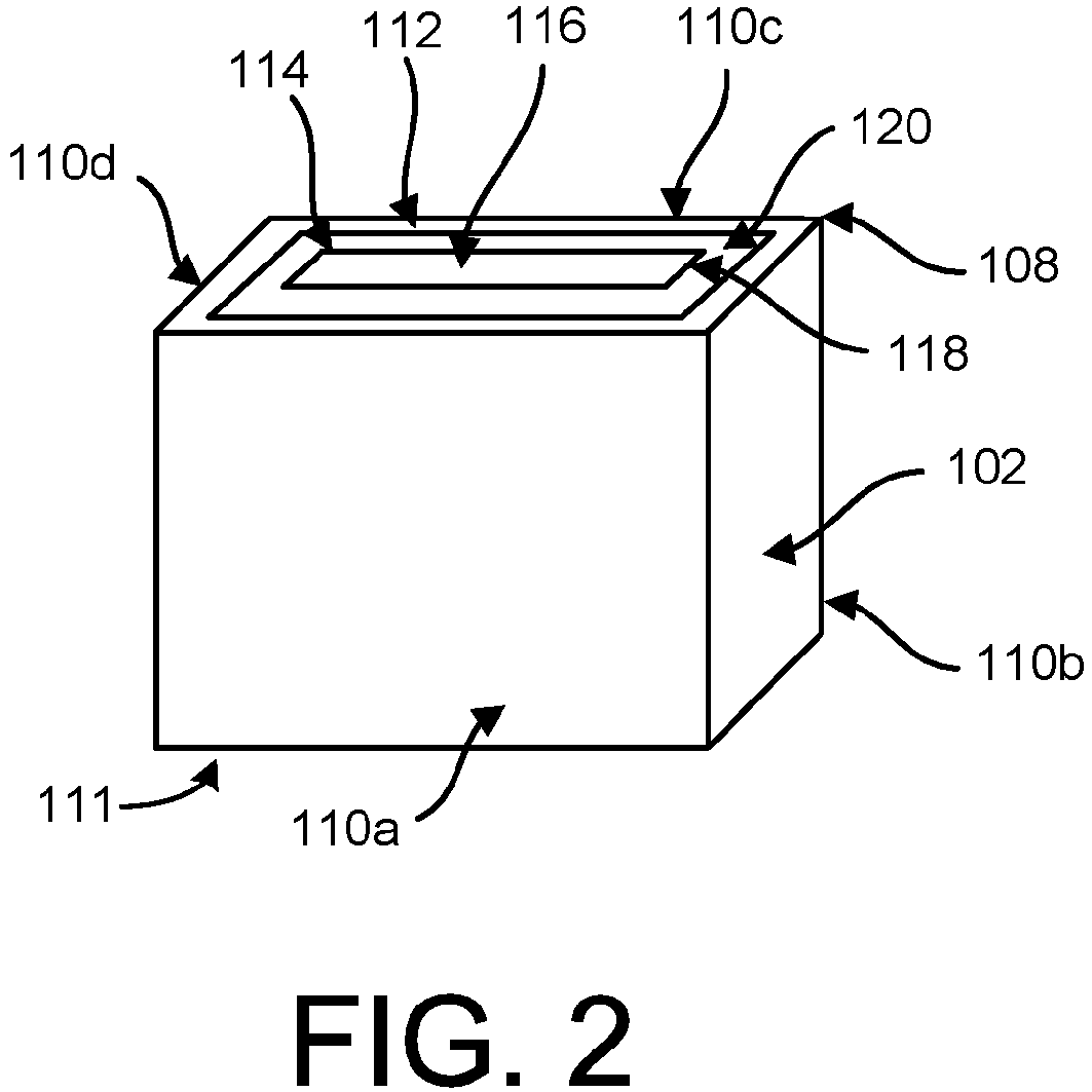
- Figure 2 illustrates an example of the base 102.
- the base 102 has the opening 108 and walls 110a-d and a floor 111 defining an internal area 112, and a sleeve 114 with a portion of the sleeve 114 positioned in the internal area 112 and around a perimeter of the walls 110a-d.
- the internal area 112 may comprise a void of the base 102.
- Figure 2 illustrates an entirety of the sleeve 114 positioned in the internal area 112, however, in other examples, the sleeve 114 may extend out of the base 102.
- the floor 111 of the base 102 may include slots or grooves (not shown) to insert the sleeve 114 into the base 102.
- the sleeve 114 defines a region 116 of the internal area 112 for placing an object (e.g., shown in Figure 5 ), and the sleeve 114 has an opening 118 for placing the object into the region 116.
- the sleeve 114 may be rigid or flexible depending on a material used. Examples of the sleeve 114 include an aluminum or a steel frame.
- the base 102 also includes a first fire suppressing powder 120 positioned in the internal area 112 between the sleeve 114 and the walls 110a-d.
- Figure 3 illustrates an example of the lid 104 that includes a cavity 122 (shown in Figure 8 ), and a divider 106 positioned to cover the cavity 122 of the lid 104.
- FIG 4 illustrates an example of the lid 104 including a second fire suppressing powder 126 contained inside the cavity 122.
- the divider 106 is removable from the lid 104 to release the second fire suppressing powder 126.
- the divider 106 includes one or more divider pull tabs, such as tab 128, attached to the divider 106, and the divider 106 is removable from the lid 104 via the tab 128 to release the second fire suppressing powder 126.
- the tab 128 is shown attached to a side of the divider 106, and the tab 128 may be attached to either side of the divider 106.
- any of the base 102, the lid 104, the sleeve 114, or the divider 106 may be aluminum or steel or a combination of aluminum and steel materials.
- any of the base 102, the lid 104, the sleeve 114, or the divider 106 may include a steel lining to handle high temperatures.
- the first fire suppressing powder 120 may provide sufficient thermal isolation, and act as a liner to the base 102, so that any further thermal liner or thermal barrier of the base 102 is not needed.
- the first fire suppressing powder 120 and the second fire suppressing powder 126 may be any types of powder or substances that are beneficial for suppressing a fire, and the type of powder is dependent on an application of the apparatus 100 as to types of fires to suppress.
- the first fire suppressing powder 120 and the second fire suppressing powder 126 can include one or more of sand, powdered graphite, or copper powder. Additional examples of powders that can be used include talcum powder, baking soda, ABC dry chemical, soda (sodium carbonate), LITH-X (powdered graphite), dry ground dolomite, or soda ash may also be used.
- the powders are fire retardant powders that engulf the fire and prevent spreading of the fire, and the first fire suppressing powder 120 and the second fire suppressing powder 126 can be any combination of powders described herein as well.
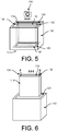
- Figures 5-7 illustrate example use of the base 102 for suppressing, containing, and/or extinguishing a fire of an object.
- the sleeve 114 is shown to include sleeve tabs 130 and 132 attached to sides of the sleeve 114.
- the sleeve tabs 130 and 132 include two sleeve tabs each attached to either side of the sleeve 114.
- An object 134 is positioned into the region 116 of the internal area 112.
- the object 134 is shown as a consumer electronics device, e.g., a digital camera. However, any object or type of object can be positioned into the region 116 based on size of the object and size of the region 116.
- the apparatus 100 is portable, and may include dimensions of about 18-20 inches wide, by 12 inches length, by 12 inches in height as one example. Of course, the apparatus 100 may be smaller or larger depending on an application or types of objects desired to be placed into the apparatus 100.
- the apparatus 100 is scalable such that many different sizes as possible and an aircraft may be provided with multiple apparatuses 100 for different objects, such as a small size apparatus 100 for cameras, mobile phones, etc., and a large size apparatus 100 for computers, video cameras, etc.
- Figure 5 also illustrates that the base 102 can also include a thermal isolation insert 136 positioned at the floor 111 of the base 102 to provide additional thermal isolation.
- the insert 136 may comprise a stainless steel material to handle high temperatures.
- the insert 136 is not included, and the floor 111 of the base 102 itself may comprise stainless steel to handle high temperatures, while a remainder of the base 102 can be aluminum.
- a layer of the first fire suppressing powder 138 is positioned at the floor 111 of the base 102 and on top of the insert 136, if included. The sleeve 114 then extends to the layer of the first fire suppressing powder 120 positioned at the floor 111 of the base 102.
- Figure 6 illustrates the base 102 with the sleeve 114 being removed.
- the sleeve 114 is removable from the base 102 to cause or allow the first fire suppressing powder 120 to collapse on a portion of the region 116 of the internal area 112 for placing the object 134.
- the sleeve 114 is removable from the base 102 via the sleeve tabs 130 and 132 causing the first fire suppressing powder 120 to collapse on a portion of the region 116 of the internal area 112 for placing the object 134.
- the sleeve 114 may be positioned in the internal area 112 spaced apart from the walls 110a-d by about 1-2 inches (which can vary based on width of the apparatus 100), and the space between the sleeve 114 and the walls 110a-d is filled with the first fire suppressing powder 120.
- the space between the sleeve 114 and the walls 110a-d can be filled entirely with the first fire suppressing powder 120 or possibly only partly filled with the first fire suppressing powder 120. In any event, removal of the sleeve 114 allows the first fire suppressing powder 120 to fall onto any object positioned in the region 116.
- the sleeve 114 is removable from the base 102
- the sleeve 114 comprises a flammable material, and based on the sleeve 114 becoming inflamed due to placing an object on fire into the region 116, the first fire suppressing powder 120 collapses on a portion of the region 116 of the internal area 112 once the sleeve 114 burns away.
- the sleeve 114 may comprise a wax material that melts when on fire or due to increased temperatures.
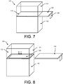
- Figure 7 illustrates an example of the apparatus 100 with the lid 104 attached to the base 102.
- the lid 104 may be snapped onto the base 102 or slide onto the base 102, and can be fully removed. In other examples, the lid 104 is hingedly attached to the base 102 through a hinge 140. Within examples, the lid 104 may overlap the base 102 such that after removal of the divider 106, the opening 108 of the base 102 is enclosed by the lid 104 and the apparatus 100 is fully enclosed. In this way, noxious fumes remain inside the apparatus 100.
- Figure 8 illustrates an example of the apparatus 100 with the lid 104 attached to the base 102, and the divider 106 removed.
- the divider 106 is removable from the lid 104 to release the second fire suppressing powder 126 into the internal area 112 of the base 102.
- the cavity 122 of the lid 104 can be full of the second fire suppressing powder 126, and after removal of the divider 106, the second fire suppressing powder 126 falls down into the internal area 112 of the base 102 and covers the object 134 to further suppress and extinguish the fire.
- the divider 106 can be manually removed by sliding the divider 106 out of the apparatus 100.
- a crew member can carry the apparatus 100 to a point of the object 134 on fire.
- the crew member may use a tool (not shown and may include tongs to grip the object 134, or pliers/vice grips with a safety mechanism or shield to protect the user) for safely handling the object 134 on fire.
- the lid 104 can be removed and the object 134 on fire can be positioned into the region 116 inside the sleeve 114. Following, the sleeve 114 is removed causing the first fire suppressing powder 120 to fall into the region 116 and bury or partially bury the object 134 on fire.
- the object 134 may be fully covered by the first fire suppressing powder 120, and to ensure that the object 134 is fully covered by fire retardants, the lid 104 is then positioned onto the base 102 and the divider 106 is removed causing the second fire suppressing powder 126 in the lid 104 to fall down and bury the object 134 on fire. This can completely bury the object 134 in fire retardant powder and provide thermal insulation between the fire and an ambient environment. As a result, the apparatus 100 contains the fire, suppresses the fire, and extinguishes the fire.
- Both the lid 104 and the base 102 containing fire retardant powders.
- An amount of the first fire suppressing powder 120 contained in the base 102 combined with an amount of the second fire suppressing powder 126 contained in the lid 104 substantially fills the internal area 112 of the base 102.
- Specific amounts of the powder depend on a size and dimensions of the apparatus 100. However, together, amounts of powder contained in the lid 104 and the base 102 can be enough to about fill the internal area 112 of the base 102.
- the lid 104 may contain more amount of powder than in the base 102, or the amount of powder in the lid 104 as compared to the base 102 can be in a ratio of 1:1, or 1:2, or 2:1, depending on sizes of the lid 104 and the base 102.
- Figure 9 illustrates an example of the apparatus 100 with the lid 104 attached to the base 102, and the lid 104 includes venting capabilities.
- the lid 104 is shown to include louvers 150 that can open and close to vent the apparatus 100. In this manner, fumes or smoke can be vented out of the apparatus 100 through the louvers 150.
- FIG 10 illustrates an example of the apparatus 100 with the lid 104 attached to the base 102, and the lid 104 includes an air filtration device 152 adjacent the cavity 122.
- the air filtration device 152 includes the louvers 150 and also a region 154 containing activated carbon and a catalyst for scrubbing air to remove chemicals.
- the air filtration device 152 can reduce noxious fumes from entering a cabin of an aircraft.
- Activated carbon is carbon that has been treated with oxygen to adsorb certain chemicals that are attracted to the activated carbon. Catalysts can be added to enable the air filtration device 152 to attract non-carbon based chemicals as well.
- the air filtration device 152 can filter any fumes resulting from extinguishing the fire.
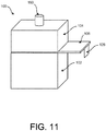
- Figure 11 illustrates an example of the apparatus 100 with the lid 104 attached to the base 102, and the lid 104 includes a vent 160 for connection to a hose enabling exhaustion of fumes.
- the vent 160 can connect to a hose of a portable scrubber that includes activated carbon and a catalyst, or the vent 160 can connect to a hose of the aircraft to vent to an ambient environment outside the aircraft, for example.
- Figure 12 shows a flowchart of an example method 200 for suppressing a fire of the object 134, according to an example.
- Method 200 shown in Figure 12 presents an example of a method that, for example, could be used with the apparatus 100 as shown and described herein, for example. It should be understood that for this and other processes and methods disclosed herein, flowcharts show functionality and operation of one possible implementation of present examples. Alternative implementations are included within the scope of the example of the present disclosure in which functions may be executed out of order from that shown or discussed, including substantially concurrent or in reverse order, depending on the functionality involved, as would be understood by those reasonably skilled in the art.
- the method 200 includes placing the object 134 into the region 116 of the internal area 112 of the base 102 defined by the sleeve 114.
- the base 102 has the opening 108 and the walls 110a-d defining the internal area 112, and the base 102 includes the sleeve 114 with a portion positioned in the internal area 112 and around a perimeter of the walls 110a-d that defines the region 116 of the internal area 112 for placing the object 134.
- the base 102 further comprises the first fire suppressing powder 120 positioned in the internal area 112 between the sleeve 114 and the walls 110a-d.
- the method 200 includes removing the sleeve 114 from the base 102 causing the first fire suppressing powder 120 to collapse on a portion of the region 116 of the internal area 112 for placing the object 134.
- the method 200 includes covering the opening 108 of the base 102 with the lid 104.
- the lid 104 has the cavity 122 and the second fire suppressing powder 126 is contained inside the cavity 122.
- the lid 104 comprises the divider 106 positioned to cover the cavity 122 of the lid 104.
- the method 200 includes removing the divider 106 from the lid 104 to release the second fire suppressing powder 126 into the internal area 112 of the base 102. This causes the object 134 to be covered with fire retardant powder to suppress and extinguish the fire.
- Figure 13 shows a flowchart of an example method for use with the method 200, according to an example.
- functions include removing the divider 106 from the lid 104 to release the second fire suppressing powder 126 into the internal area 112 of the base 102 and substantially covering the object 134 with the second fire suppressing powder 126.
- an amount of the first fire suppressing powder 120 contained in the base 102 combined with an amount of the second fire suppressing powder 126 contained in the lid 104 substantially fills the internal area 112 of the base 102.
- Figure 14 shows a flowchart of another example method 250 for suppressing a fire of the object 134, according to an example.
- Method 250 shown in Figure 12 presents an example of a method that, for example, could be used with the apparatus 100 as shown and described herein, for example.
- the method 250 includes positioning the first fire suppressing powder 120 in the internal area 112 of the base 102 that has the opening 108 and the walls 110a-d defining the internal area 112, and the base 102 includes the sleeve 114 in the internal area 112 and around a perimeter of the walls 110a-d that defines the region 116 of the internal area 112 for placing the object 134.
- the method 250 includes collapsing the first fire suppressing powder 120 on a portion of the region 116 of the internal area 112 for placing the object 134 by removal of the sleeve 114.
- the method 250 includes covering the opening 108 of the base 102 with the lid 104.
- the lid 104 has the cavity 122 and the second fire suppressing powder 126 contained inside the cavity 122.
- the method 250 includes releasing the second fire suppressing powder 126 into the internal area 112 of the base 102.
- FIG. 15 shows a flowchart of an example method for use with the method 250, according to an example. 20.
- the lid 104 includes the divider 106 positioned to cover the cavity 122 of the lid 104.
- functions include removing the divider 106 from the lid 104 to release the second fire suppressing powder 126 into the internal area 112 of the base 102.
- the apparatus 100 may be used in many other applications, such as on commercial and public bus or trains.
- the apparatus 100 is a portable container that can be used for any public or private transportation, or in any setting (not just transportation related). Also, the apparatus 100 can be designed to accommodate any type of object on fire depending on a size of the apparatus 100 as well as a type of fire retardant powder included in the base 102 and the lid 104.
Landscapes
- Health & Medical Sciences (AREA)
- Public Health (AREA)
- Business, Economics & Management (AREA)
- Emergency Management (AREA)
- Chemical & Material Sciences (AREA)
- Engineering & Computer Science (AREA)
- Chemical Kinetics & Catalysis (AREA)
- General Chemical & Material Sciences (AREA)
- Oil, Petroleum & Natural Gas (AREA)
- Fire-Extinguishing Compositions (AREA)
- Fire-Extinguishing By Fire Departments, And Fire-Extinguishing Equipment And Control Thereof (AREA)
- Building Environments (AREA)
Abstract
Description
- The present disclosure generally relates to a fire suppression apparatus for containing, suppressing, and extinguishing a fire of an object, and more particularly to extinguishing a fire of an object caused by a lithium battery exhibiting thermal runaway.
- Several systems have attempted to deal with issues of fire suppression of object due to electrical fires and lithium-ion battery fires in particular. In the aircraft industry, fires that may occur in flight can be very dangerous. Many consumer electrical devices are present onboard the aircraft, including cell phones, computers, card scanners, etc., that utilize lithium batteries, and such batteries if damaged may catch on fire. A lithium battery exhibiting thermal runaway must be disposed of properly to avoid further complications, and often times, onboard an aircraft in flight, proper disposal may be difficult.
- Devices exist for attempting to suppress fires and in particular electrical or chemical fires in which water or typical fire extinguishers are insufficient, that include a volume sufficient to contain the electrical device and a covers for containing the fire within the device preventing spread of the fire. However, many of existing devices do not contemplate a thermal runaway reaction or a resulting fire that will continue, but rather are focused on isolating the dangerous condition.
- What is needed is a method for handling a fire, such as a consumer electronics lithium ion battery fire, in a cabin of an aircraft during flight.
- In one example, a fire suppression apparatus is described that comprises a base that has an opening. The base comprises walls defining an internal area, and a sleeve with a portion positioned in the internal area and around a perimeter of the walls. The sleeve defines a region of the internal area for placing an object, and the sleeve has an opening for placing the object into the region. The base further comprises a first fire suppressing powder positioned in the internal area between the sleeve and the walls. The fire suppression apparatus also comprise a lid for covering the opening of the base. The lid comprises a cavity, a second fire suppressing powder contained inside the cavity, and a divider positioned to cover the cavity of the lid.
- In another example, a method for suppressing a fire of an object is described. The method comprises placing the object into a region of an internal area of a base defined by a sleeve. The base has an opening and walls defining the internal area, and the base includes the sleeve with a portion positioned in the internal area and around a perimeter of the walls that defines the region of the internal area for placing the object. The base further comprises a first fire suppressing powder positioned in the internal area between the sleeve and the walls. The method also comprises removing the sleeve from the base causing the first fire suppressing powder to collapse on a portion of the region of the internal area for placing the object, and covering the opening of the base with a lid. The lid has a cavity and a second fire suppressing powder contained inside the cavity, and the lid comprises a divider positioned to cover the cavity of the lid. The method also comprises removing the divider from the lid to release the second fire suppressing powder into the internal area of the base.
- In another example, another method for suppressing a fire of an object is described that comprises positioning a first fire suppressing powder in an internal area of a base that has an opening and walls defining the internal area, and the base includes a sleeve in the internal area and around a perimeter of the walls that defines a region of the internal area for placing an object. The method also comprises collapsing the first fire suppressing powder on a portion of the region of the internal area for placing the object by removal of the sleeve and covering the opening of the base with a lid. The lid has a cavity and a second fire suppressing powder contained inside the cavity. The method also comprises releasing the second fire suppressing powder into the internal area of the base.
- The features, functions, and advantages that have been discussed can be achieved independently in various examples or may be combined in yet other examples further details of which can be seen with reference to the following description and drawings.
- The novel features believed characteristic of the illustrative examples are set forth in the appended claims. The illustrative examples, however, as well as a preferred mode of use, further objectives and descriptions thereof, will best be understood by reference to the following detailed description of an illustrative example of the present disclosure when read in conjunction with the accompanying drawings.
-
Figure 1 illustrates an example fire suppression apparatus. -
Figure 2 illustrates an example of a base of the apparatus. -
Figure 3 illustrates an example of a lid and a divider of the apparatus. -
Figure 4 illustrates an example of the lid including a second fire suppressing powder contained inside the cavity. -
Figure 5 illustrates an example use of the base for suppressing, containing, and/or extinguishing a fire of an object. -
Figure 6 illustrates the base with the sleeve being removed. -
Figure 7 illustrates an example of the apparatus with the lid attached to the base. -
Figure 8 illustrates an example of the apparatus with the lid attached to the base, and the divider removed. -
Figure 9 illustrates an example of the apparatus with the lid attached to the base, and the lid includes venting capabilities. -
Figure 10 illustrates an example of the apparatus with the lid attached to the base, and the lid includes an air filtration device adjacent the cavity. -
Figure 11 illustrates an example of the apparatus with the lid attached to the base, and the lid includes a vent for connection to a hose enabling exhaustion of fumes. -
Figure 12 shows a flowchart of an example method for suppressing a fire of the object. -
Figure 13 shows a flowchart of an example method for use with the method shown inFigure 12 . -
Figure 14 shows a flowchart of another example method for suppressing a fire of the object. -
Figure 15 shows a flowchart of an example method for use with the method shown inFigure 14 . - Disclosed examples will now be described more fully hereinafter with reference to the accompanying drawings, in which some, but not all of the disclosed examples are shown. Indeed, several different examples may be described and should not be construed as limited to the examples set forth herein. Rather, these embodiments are described so that this disclosure will be thorough and complete and will fully convey the scope of the disclosure to those skilled in the art.
- Within examples, a fire suppression, containment, and extinguishing apparatus is described. The apparatus may be useful for an aircraft passenger battery fire suppression system to handle lithium battery fires in a cabin of an aircraft carrying passengers to improve safety of passengers on board. A base including a fire suppressing powder is used, for example, to engulf a burning consumer electronics device containing lithium ion batteries in flight. In addition, methods of scrubbing exhaust gasses are described to help prevent noxious fumes from entering the cabin. Additional venting methods are described to vent to an existing aircraft exhaust vent system.
- Referring now to
Figure 1 , an examplefire suppression apparatus 100 is illustrated. Theapparatus 100 includes abase 102, alid 104, and adivider 106. Thelid 104 covers an opening 108 of thebase 102. Theapparatus 100 is a portable container. In some examples, as shown inFigure 1 , theapparatus 100 may includehandles 105a-b on either side of thebase 102 for carrying theapparatus 100. -
Figure 2 illustrates an example of thebase 102. Thebase 102 has the opening 108 andwalls 110a-d and afloor 111 defining aninternal area 112, and asleeve 114 with a portion of thesleeve 114 positioned in theinternal area 112 and around a perimeter of thewalls 110a-d. Theinternal area 112 may comprise a void of thebase 102.Figure 2 illustrates an entirety of thesleeve 114 positioned in theinternal area 112, however, in other examples, thesleeve 114 may extend out of thebase 102. Thefloor 111 of thebase 102 may include slots or grooves (not shown) to insert thesleeve 114 into thebase 102. - The
sleeve 114 defines aregion 116 of theinternal area 112 for placing an object (e.g., shown inFigure 5 ), and thesleeve 114 has anopening 118 for placing the object into theregion 116. Thesleeve 114 may be rigid or flexible depending on a material used. Examples of thesleeve 114 include an aluminum or a steel frame. - The base 102 also includes a first
fire suppressing powder 120 positioned in theinternal area 112 between thesleeve 114 and thewalls 110a-d. -
Figure 3 illustrates an example of thelid 104 that includes a cavity 122 (shown inFigure 8 ), and adivider 106 positioned to cover thecavity 122 of thelid 104. -
Figure 4 illustrates an example of thelid 104 including a secondfire suppressing powder 126 contained inside thecavity 122. As shown inFigure 4 , thedivider 106 is removable from thelid 104 to release the secondfire suppressing powder 126. Thedivider 106 includes one or more divider pull tabs, such astab 128, attached to thedivider 106, and thedivider 106 is removable from thelid 104 via thetab 128 to release the secondfire suppressing powder 126. Thetab 128 is shown attached to a side of thedivider 106, and thetab 128 may be attached to either side of thedivider 106. - Any of the
base 102, thelid 104, thesleeve 114, or thedivider 106 may be aluminum or steel or a combination of aluminum and steel materials. In other examples, any of thebase 102, thelid 104, thesleeve 114, or thedivider 106 may include a steel lining to handle high temperatures. In still further examples, the firstfire suppressing powder 120 may provide sufficient thermal isolation, and act as a liner to thebase 102, so that any further thermal liner or thermal barrier of thebase 102 is not needed. - The first
fire suppressing powder 120 and the secondfire suppressing powder 126 may be any types of powder or substances that are beneficial for suppressing a fire, and the type of powder is dependent on an application of theapparatus 100 as to types of fires to suppress. For example, to suppress a fire of a lithium-ion battery, one or both of the firstfire suppressing powder 120 and the secondfire suppressing powder 126 can include one or more of sand, powdered graphite, or copper powder. Additional examples of powders that can be used include talcum powder, baking soda, ABC dry chemical, soda (sodium carbonate), LITH-X (powdered graphite), dry ground dolomite, or soda ash may also be used. The powders are fire retardant powders that engulf the fire and prevent spreading of the fire, and the firstfire suppressing powder 120 and the secondfire suppressing powder 126 can be any combination of powders described herein as well. -
Figures 5-7 illustrate example use of thebase 102 for suppressing, containing, and/or extinguishing a fire of an object. InFigure 5 , thesleeve 114 is shown to includesleeve tabs sleeve 114. Thesleeve tabs sleeve 114. Anobject 134 is positioned into theregion 116 of theinternal area 112. Theobject 134 is shown as a consumer electronics device, e.g., a digital camera. However, any object or type of object can be positioned into theregion 116 based on size of the object and size of theregion 116. Theapparatus 100 is portable, and may include dimensions of about 18-20 inches wide, by 12 inches length, by 12 inches in height as one example. Of course, theapparatus 100 may be smaller or larger depending on an application or types of objects desired to be placed into theapparatus 100. Theapparatus 100 is scalable such that many different sizes as possible and an aircraft may be provided withmultiple apparatuses 100 for different objects, such as asmall size apparatus 100 for cameras, mobile phones, etc., and alarge size apparatus 100 for computers, video cameras, etc. -
Figure 5 also illustrates that the base 102 can also include athermal isolation insert 136 positioned at thefloor 111 of the base 102 to provide additional thermal isolation. As an example, theinsert 136 may comprise a stainless steel material to handle high temperatures. In other examples, theinsert 136 is not included, and thefloor 111 of the base 102 itself may comprise stainless steel to handle high temperatures, while a remainder of the base 102 can be aluminum. A layer of the firstfire suppressing powder 138 is positioned at thefloor 111 of thebase 102 and on top of theinsert 136, if included. Thesleeve 114 then extends to the layer of the firstfire suppressing powder 120 positioned at thefloor 111 of thebase 102. -
Figure 6 illustrates the base 102 with thesleeve 114 being removed. Thesleeve 114 is removable from the base 102 to cause or allow the firstfire suppressing powder 120 to collapse on a portion of theregion 116 of theinternal area 112 for placing theobject 134. Thesleeve 114 is removable from thebase 102 via thesleeve tabs fire suppressing powder 120 to collapse on a portion of theregion 116 of theinternal area 112 for placing theobject 134. Thesleeve 114 may be positioned in theinternal area 112 spaced apart from thewalls 110a-d by about 1-2 inches (which can vary based on width of the apparatus 100), and the space between thesleeve 114 and thewalls 110a-d is filled with the firstfire suppressing powder 120. The space between thesleeve 114 and thewalls 110a-d can be filled entirely with the firstfire suppressing powder 120 or possibly only partly filled with the firstfire suppressing powder 120. In any event, removal of thesleeve 114 allows the firstfire suppressing powder 120 to fall onto any object positioned in theregion 116. - While
Figure 6 illustrates that thesleeve 114 is removable from thebase 102, in other examples, thesleeve 114 comprises a flammable material, and based on thesleeve 114 becoming inflamed due to placing an object on fire into theregion 116, the firstfire suppressing powder 120 collapses on a portion of theregion 116 of theinternal area 112 once thesleeve 114 burns away. As one example, thesleeve 114 may comprise a wax material that melts when on fire or due to increased temperatures. -
Figure 7 illustrates an example of theapparatus 100 with thelid 104 attached to thebase 102. Once theobject 134 on fire is positioned into theregion 116 of thebase 102 and thesleeve 114 is removed, the firstfire suppressing powder 120 collapses on a portion of theregion 116 of theinternal area 112 to cover at least a portion of theobject 134 on fire. This may extinguish the fire, or could extinguish a portion of the fire of theobject 134. Then, by placing thelid 104 to cover theopening 108 of thebase 102, theinternal area 112 of thebase 102 is now enclosed so as to contain the fire in theapparatus 100. - The
lid 104 may be snapped onto the base 102 or slide onto thebase 102, and can be fully removed. In other examples, thelid 104 is hingedly attached to the base 102 through ahinge 140. Within examples, thelid 104 may overlap the base 102 such that after removal of thedivider 106, theopening 108 of thebase 102 is enclosed by thelid 104 and theapparatus 100 is fully enclosed. In this way, noxious fumes remain inside theapparatus 100. -
Figure 8 illustrates an example of theapparatus 100 with thelid 104 attached to thebase 102, and thedivider 106 removed. Thedivider 106 is removable from thelid 104 to release the secondfire suppressing powder 126 into theinternal area 112 of thebase 102. Thecavity 122 of thelid 104 can be full of the secondfire suppressing powder 126, and after removal of thedivider 106, the secondfire suppressing powder 126 falls down into theinternal area 112 of thebase 102 and covers theobject 134 to further suppress and extinguish the fire. Thedivider 106 can be manually removed by sliding thedivider 106 out of theapparatus 100. - As an example use of the
apparatus 100 onboard an aircraft in flight, a crew member can carry theapparatus 100 to a point of theobject 134 on fire. The crew member may use a tool (not shown and may include tongs to grip theobject 134, or pliers/vice grips with a safety mechanism or shield to protect the user) for safely handling theobject 134 on fire. Thelid 104 can be removed and theobject 134 on fire can be positioned into theregion 116 inside thesleeve 114. Following, thesleeve 114 is removed causing the firstfire suppressing powder 120 to fall into theregion 116 and bury or partially bury theobject 134 on fire. At this point, theobject 134 may be fully covered by the firstfire suppressing powder 120, and to ensure that theobject 134 is fully covered by fire retardants, thelid 104 is then positioned onto thebase 102 and thedivider 106 is removed causing the secondfire suppressing powder 126 in thelid 104 to fall down and bury theobject 134 on fire. This can completely bury theobject 134 in fire retardant powder and provide thermal insulation between the fire and an ambient environment. As a result, theapparatus 100 contains the fire, suppresses the fire, and extinguishes the fire. - Both the
lid 104 and the base 102 containing fire retardant powders. An amount of the firstfire suppressing powder 120 contained in the base 102 combined with an amount of the secondfire suppressing powder 126 contained in thelid 104 substantially fills theinternal area 112 of thebase 102. Specific amounts of the powder depend on a size and dimensions of theapparatus 100. However, together, amounts of powder contained in thelid 104 and the base 102 can be enough to about fill theinternal area 112 of thebase 102. By the term "substantially" it is meant that the recited characteristic, parameter, or value need not be achieved exactly, but that deviations or variations, including for example, tolerances, measurement error, measurement accuracy limitations and other factors known to skill in the art, may occur in amounts that do not preclude the effect the characteristic was intended to provide. - In some examples, the
lid 104 may contain more amount of powder than in thebase 102, or the amount of powder in thelid 104 as compared to the base 102 can be in a ratio of 1:1, or 1:2, or 2:1, depending on sizes of thelid 104 and thebase 102. -
Figure 9 illustrates an example of theapparatus 100 with thelid 104 attached to thebase 102, and thelid 104 includes venting capabilities. For example, thelid 104 is shown to includelouvers 150 that can open and close to vent theapparatus 100. In this manner, fumes or smoke can be vented out of theapparatus 100 through thelouvers 150. -
Figure 10 illustrates an example of theapparatus 100 with thelid 104 attached to thebase 102, and thelid 104 includes anair filtration device 152 adjacent thecavity 122. Theair filtration device 152 includes thelouvers 150 and also aregion 154 containing activated carbon and a catalyst for scrubbing air to remove chemicals. Theair filtration device 152 can reduce noxious fumes from entering a cabin of an aircraft. Activated carbon is carbon that has been treated with oxygen to adsorb certain chemicals that are attracted to the activated carbon. Catalysts can be added to enable theair filtration device 152 to attract non-carbon based chemicals as well. Thus, theair filtration device 152 can filter any fumes resulting from extinguishing the fire. -
Figure 11 illustrates an example of theapparatus 100 with thelid 104 attached to thebase 102, and thelid 104 includes avent 160 for connection to a hose enabling exhaustion of fumes. Thevent 160 can connect to a hose of a portable scrubber that includes activated carbon and a catalyst, or thevent 160 can connect to a hose of the aircraft to vent to an ambient environment outside the aircraft, for example. -
Figure 12 shows a flowchart of anexample method 200 for suppressing a fire of theobject 134, according to an example.Method 200 shown inFigure 12 presents an example of a method that, for example, could be used with theapparatus 100 as shown and described herein, for example. It should be understood that for this and other processes and methods disclosed herein, flowcharts show functionality and operation of one possible implementation of present examples. Alternative implementations are included within the scope of the example of the present disclosure in which functions may be executed out of order from that shown or discussed, including substantially concurrent or in reverse order, depending on the functionality involved, as would be understood by those reasonably skilled in the art. - At
block 202, themethod 200 includes placing theobject 134 into theregion 116 of theinternal area 112 of the base 102 defined by thesleeve 114. Thebase 102 has theopening 108 and thewalls 110a-d defining theinternal area 112, and thebase 102 includes thesleeve 114 with a portion positioned in theinternal area 112 and around a perimeter of thewalls 110a-d that defines theregion 116 of theinternal area 112 for placing theobject 134. The base 102 further comprises the firstfire suppressing powder 120 positioned in theinternal area 112 between thesleeve 114 and thewalls 110a-d. - At
block 204, themethod 200 includes removing thesleeve 114 from the base 102 causing the firstfire suppressing powder 120 to collapse on a portion of theregion 116 of theinternal area 112 for placing theobject 134. - At
block 206, themethod 200 includes covering theopening 108 of the base 102 with thelid 104. Thelid 104 has thecavity 122 and the secondfire suppressing powder 126 is contained inside thecavity 122. Thelid 104 comprises thedivider 106 positioned to cover thecavity 122 of thelid 104. - At
block 208, themethod 200 includes removing thedivider 106 from thelid 104 to release the secondfire suppressing powder 126 into theinternal area 112 of thebase 102. This causes theobject 134 to be covered with fire retardant powder to suppress and extinguish the fire. -
Figure 13 shows a flowchart of an example method for use with themethod 200, according to an example. Atblock 210, functions include removing thedivider 106 from thelid 104 to release the secondfire suppressing powder 126 into theinternal area 112 of thebase 102 and substantially covering theobject 134 with the secondfire suppressing powder 126. In this example, an amount of the firstfire suppressing powder 120 contained in the base 102 combined with an amount of the secondfire suppressing powder 126 contained in thelid 104 substantially fills theinternal area 112 of thebase 102. -
Figure 14 shows a flowchart of anotherexample method 250 for suppressing a fire of theobject 134, according to an example.Method 250 shown inFigure 12 presents an example of a method that, for example, could be used with theapparatus 100 as shown and described herein, for example. - At
block 252, themethod 250 includes positioning the firstfire suppressing powder 120 in theinternal area 112 of the base 102 that has theopening 108 and thewalls 110a-d defining theinternal area 112, and thebase 102 includes thesleeve 114 in theinternal area 112 and around a perimeter of thewalls 110a-d that defines theregion 116 of theinternal area 112 for placing theobject 134. - At
block 254, themethod 250 includes collapsing the firstfire suppressing powder 120 on a portion of theregion 116 of theinternal area 112 for placing theobject 134 by removal of thesleeve 114. - At
block 256, themethod 250 includes covering theopening 108 of the base 102 with thelid 104. Thelid 104 has thecavity 122 and the secondfire suppressing powder 126 contained inside thecavity 122. - At
block 258, themethod 250 includes releasing the secondfire suppressing powder 126 into theinternal area 112 of thebase 102. -
Figure 15 shows a flowchart of an example method for use with themethod 250, according to an example. 20. Thelid 104 includes thedivider 106 positioned to cover thecavity 122 of thelid 104. Atblock 260, functions include removing thedivider 106 from thelid 104 to release the secondfire suppressing powder 126 into theinternal area 112 of thebase 102. - Although many examples described herein include use of the
apparatus 100 onboard an aircraft, theapparatus 100 may be used in many other applications, such as on commercial and public bus or trains. Theapparatus 100 is a portable container that can be used for any public or private transportation, or in any setting (not just transportation related). Also, theapparatus 100 can be designed to accommodate any type of object on fire depending on a size of theapparatus 100 as well as a type of fire retardant powder included in thebase 102 and thelid 104. - Further, the disclosure comprises examples according to the following clauses:
- Clause A1. A fire suppression apparatus (100), comprising:
- a base (102) having an opening (108) and comprising:
- walls (110a-d) defining an internal area (112);
- a sleeve (114) with a portion positioned in the internal area (112) and around a perimeter of the walls (110a-d), the sleeve (114) defining a region (116) of the internal area (112) for placing an object, and the sleeve (114) having an opening (118) for placing the object into the region (116);
- a first fire suppressing powder (120) positioned in the internal area (112) between the sleeve (114) and the walls (110a-d); and
- a lid (104) for covering the opening (108) of the base (102), wherein the lid (104) comprises:
- a cavity (122);
- a second fire suppressing powder (126) contained inside the cavity (122); and
- a divider (106) positioned to cover the cavity (122) of the lid (104).
- a base (102) having an opening (108) and comprising:
- Clause A2. The fire suppression apparatus (100) of clause A1, wherein the sleeve (114) is removable from the base (102) causing the first fire suppressing powder (120) to collapse on a portion of the region (116) of the internal area (112) for placing the object.
- Clause A3. The fire suppression apparatus (100) of clause A1 or A2, further comprising one or more sleeve tabs (130, 132) attached to the sleeve (114), wherein the sleeve (114) is removable from the base (102) via the one or more sleeve tabs (130, 132) causing the first fire suppressing powder (120) to collapse on a portion of the region (116) of the internal area (112) for placing the object.
- Clause A4. The fire suppression apparatus (100) of any of clauses A1-A3, wherein the sleeve (114) comprises a flammable material, and based on the sleeve (114) becoming inflamed, the first fire suppressing powder (120) collapses on a portion of the region (116) of the internal area (112) for placing the object.
- Clause A5. The fire suppression apparatus (100) of any of clauses A1-A4, wherein the divider (106) is removable from the lid (104) to release the second fire suppressing powder (126) into the internal area (112) of the base (102).
- Clause A6. The fire suppression apparatus (100) of any of clauses A1-A5, further comprising one or more divider pull tabs (128) attached to the divider, wherein the divider (106) is removable from the lid (104) via the one or more divider pull tabs (128) to release the second fire suppressing powder (126) into the internal area (112) of the base (102).
- Clause A7. The fire suppression apparatus (100) of any of clauses A1-A6, wherein an amount of the first fire suppressing powder (120) contained in the base (102) combined with an amount of the second fire suppressing powder (126) contained in the lid (104) substantially fills the internal area (112) of the base (102).
- Clause A8. The fire suppression apparatus (100) of any of clauses A1-A7, wherein the lid (104) is hingedly attached to the base (102).
- Clause A9. The fire suppression apparatus (100) of any of clauses A1-A8, wherein the lid (104) covers the opening (108) of the base (102) and encloses the internal area (112) of the base (102).
- Clause A10. The fire suppression apparatus (100) of any of clauses A1-A9, wherein the apparatus is a portable container.
- Clause A11. The fire suppression apparatus (100) of any of clauses A1-A10, further comprising a layer of the first fire suppressing powder (138) positioned at a floor (111) of the base (102).
- Clause A12. The fire suppression apparatus (100) of clause All, wherein the sleeve (114) extends to the layer of the first fire suppressing powder (138) positioned at the floor (111) of the base (102).
- Clause A13. The fire suppression apparatus (100) of any of clauses A1-A12, further comprising a thermal isolation insert (136) positioned at a floor (111) of the base (102) to provide additional thermal isolation.
- Clause A14. The fire suppression apparatus (100) of any of clauses A1-A13, wherein one or both of the first fire suppressing powder (120) and the second fire suppressing powder (126) include one or more of sand, powdered graphite, or copper powder.
- Clause A15. The fire suppression apparatus (100) of any of clauses A1-A14, wherein the lid (104) further comprises an air filtration device (152) adjacent the cavity (122).
- Clause A16. The fire suppression apparatus (100) of any of clauses A1-A15, wherein the lid (104) further comprises a vent (160) for connection to a hose enabling exhaustion of fumes.
- Clause A17. A method (200) for suppressing a fire of an object, the method comprising:
- placing the object into a region of an internal area of a base defined by a sleeve (202), wherein the base has an opening and walls defining the internal area, and the base includes the sleeve with a portion positioned in the internal area and around a perimeter of the walls that defines the region of the internal area for placing the object, wherein the base further comprises a first fire suppressing powder positioned in the internal area between the sleeve and the walls;
- removing the sleeve from the base causing the first fire suppressing powder to collapse on a portion of the region of the internal area for placing the object (204);
- covering the opening of the base with a lid, wherein the lid has a cavity and a second fire suppressing powder contained inside the cavity, and wherein the lid comprises a divider positioned to cover the cavity of the lid (206); and
- removing the divider from the lid to release the second fire suppressing powder into the internal area of the base (208).
- Clause A18. The method (200) of clause A17, wherein an amount of the first fire suppressing powder contained in the base combined with an amount of the second fire suppressing powder contained in the lid substantially fills the internal area of the base, and wherein removing the divider from the lid to release the second fire suppressing powder into the internal area of the base comprises substantially covering the object with the second fire suppressing powder (210).
- Clause A19. A method (250) for suppressing a fire of an object, the method comprising:
- positioning a first fire suppressing powder in an internal area of a base that has an opening and walls defining the internal area, and the base includes a sleeve in the internal area and around a perimeter of the walls that defines a region of the internal area for placing an object (252);
- collapsing the first fire suppressing powder on a portion of the region of the internal area for placing the object by removal of the sleeve (254);
- covering the opening of the base with a lid, wherein the lid has a cavity and a second fire suppressing powder contained inside the cavity (256); and
- releasing the second fire suppressing powder into the internal area of the base (258).
- Clause A20. The method (250) of clause A19, wherein the lid comprises a divider positioned to cover the cavity of the lid, and wherein releasing the second fire suppressing powder into the internal area of the base comprises:
- removing the divider from the lid to release the second fire suppressing powder into the internal area of the base (260).
- The description of the different advantageous arrangements has been presented for purposes of illustration and description, and is not intended to be exhaustive or limited to the examples in the form disclosed. Many modifications and variations will be apparent to those of ordinary skill in the art. Further, different advantageous examples may describe different advantages as compared to other advantageous examples. The example or examples selected are chosen and described in order to explain the principles of the examples, the practical application, and to enable others of ordinary skill in the art to understand the disclosure for various examples with various modifications as are suited to the particular use contemplated.
Claims (15)
- A fire suppression apparatus (100), comprising:a base (102) having an opening (108) and comprising:walls (110a-d) defining an internal area (112);a sleeve (114) with a portion positioned in the internal area (112) and around a perimeter of the walls (110a-d), the sleeve (114) defining a region (116) of the internal area (112) for placing an object, and the sleeve (114) having an opening (118) for placing the object into the region (116);a first fire suppressing powder (120) positioned in the internal area (112) between the sleeve (114) and the walls (110a-d); anda lid (104) for covering the opening (108) of the base (102), wherein the lid (104) comprises:a cavity (122);a second fire suppressing powder (126) contained inside the cavity (122); anda divider (106) positioned to cover the cavity (122) of the lid (104).
- The fire suppression apparatus (100) of claim 1, wherein the sleeve (114) is removable from the base (102) causing the first fire suppressing powder (120) to collapse on a portion of the region (116) of the internal area (112) for placing the object.
- The fire suppression apparatus (100) of claim 1 or 2, further comprising one or more sleeve tabs (130, 132) attached to the sleeve (114), wherein the sleeve (114) is removable from the base (102) via the one or more sleeve tabs (130, 132) causing the first fire suppressing powder (120) to collapse on a portion of the region (116) of the internal area (112) for placing the object.
- The fire suppression apparatus (100) of any of claims 1-3, wherein the sleeve (114) comprises a flammable material, and based on the sleeve (114) becoming inflamed, the first fire suppressing powder (120) collapses on a portion of the region (116) of the internal area (112) for placing the object.
- The fire suppression apparatus (100) of any of claims 1-4, wherein the divider (106) is removable from the lid (104) to release the second fire suppressing powder (126) into the internal area (112) of the base (102).
- The fire suppression apparatus (100) of any of claims 1-5, further comprising one or more divider pull tabs (128) attached to the divider, wherein the divider (106) is removable from the lid (104) via the one or more divider pull tabs (128) to release the second fire suppressing powder (126) into the internal area (112) of the base (102).
- The fire suppression apparatus (100) of any of claims 1-6, wherein an amount of the first fire suppressing powder (120) contained in the base (102) combined with an amount of the second fire suppressing powder (126) contained in the lid (104) substantially fills the internal area (112) of the base (102).
- The fire suppression apparatus (100) of any of claims 1-7, wherein the lid (104) covers the opening (108) of the base (102) and encloses the internal area (112) of the base (102).
- The fire suppression apparatus (100) of any of claims 1-8, further comprising a layer of the first fire suppressing powder (138) positioned at a floor (111) of the base (102).
- The fire suppression apparatus (100) of claim 9, wherein the sleeve (114) extends to the layer of the first fire suppressing powder (138) positioned at the floor (111) of the base (102).
- The fire suppression apparatus (100) of any of claims 1-10, further comprising a thermal isolation insert (136) positioned at a floor (111) of the base (102) to provide additional thermal isolation.
- A method (200) for suppressing a fire of an object, the method comprising:placing the object into a region of an internal area of a base defined by a sleeve (202), wherein the base has an opening and walls defining the internal area, and the base includes the sleeve with a portion positioned in the internal area and around a perimeter of the walls that defines the region of the internal area for placing the object, wherein the base further comprises a first fire suppressing powder positioned in the internal area between the sleeve and the walls;removing the sleeve from the base causing the first fire suppressing powder to collapse on a portion of the region of the internal area for placing the object (204);covering the opening of the base with a lid, wherein the lid has a cavity and a second fire suppressing powder contained inside the cavity, and wherein the lid comprises a divider positioned to cover the cavity of the lid (206); andremoving the divider from the lid to release the second fire suppressing powder into the internal area of the base (208).
- The method (200) of claim 12, wherein an amount of the first fire suppressing powder contained in the base combined with an amount of the second fire suppressing powder contained in the lid substantially fills the internal area of the base, and wherein removing the divider from the lid to release the second fire suppressing powder into the internal area of the base comprises substantially covering the object with the second fire suppressing powder (210).
- A method (250) for suppressing a fire of an object, the method comprising:positioning a first fire suppressing powder in an internal area of a base that has an opening and walls defining the internal area, and the base includes a sleeve in the internal area and around a perimeter of the walls that defines a region of the internal area for placing an object (252);collapsing the first fire suppressing powder on a portion of the region of the internal area for placing the object by removal of the sleeve (254);covering the opening of the base with a lid, wherein the lid has a cavity and a second fire suppressing powder contained inside the cavity (256); andreleasing the second fire suppressing powder into the internal area of the base (258).
- The method (250) of claim 14, wherein the lid comprises a divider positioned to cover the cavity of the lid, and wherein releasing the second fire suppressing powder into the internal area of the base comprises:removing the divider from the lid to release the second fire suppressing powder into the internal area of the base (260).
Applications Claiming Priority (1)
| Application Number | Priority Date | Filing Date | Title |
|---|---|---|---|
| US15/165,392 US10173087B2 (en) | 2016-05-26 | 2016-05-26 | Fire suppression apparatuses and methods for suppressing a fire with an object |
Publications (2)
| Publication Number | Publication Date |
|---|---|
| EP3248655A1 true EP3248655A1 (en) | 2017-11-29 |
| EP3248655B1 EP3248655B1 (en) | 2022-12-07 |
Family
ID=58772808
Family Applications (1)
| Application Number | Title | Priority Date | Filing Date |
|---|---|---|---|
| EP17172933.8A Active EP3248655B1 (en) | 2016-05-26 | 2017-05-25 | Fire suppression container and methods for suppressing a fire with an object within the container |
Country Status (3)
| Country | Link |
|---|---|
| US (1) | US10173087B2 (en) |
| EP (1) | EP3248655B1 (en) |
| JP (1) | JP6914725B2 (en) |
Cited By (1)
| Publication number | Priority date | Publication date | Assignee | Title |
|---|---|---|---|---|
| CN111703867A (en) * | 2020-06-09 | 2020-09-25 | 博众精工科技股份有限公司 | Fire water tank and electric vehicle charging and replacing station |
Families Citing this family (3)
| Publication number | Priority date | Publication date | Assignee | Title |
|---|---|---|---|---|
| US11247083B2 (en) * | 2018-06-28 | 2022-02-15 | Cellblock Fcs, Llc | Fire containment device and kit |
| US20210184195A1 (en) * | 2019-12-17 | 2021-06-17 | Ford Global Technologies, Llc | Passive thermal suppression material systems for battery packs |
| US11542091B2 (en) | 2020-07-23 | 2023-01-03 | Cellblock Fcs, Llc | Shipping package for lithium battery |
Citations (3)
| Publication number | Priority date | Publication date | Assignee | Title |
|---|---|---|---|---|
| US20130264346A1 (en) * | 2012-04-05 | 2013-10-10 | The Boeing Company | Fire Extinguishment Container |
| US20150069068A1 (en) * | 2013-09-09 | 2015-03-12 | The Boeing Company | Containers for fire containment |
| US20160059056A1 (en) * | 2014-08-28 | 2016-03-03 | Firetrace Usa, Llc | Methods and Apparatus for Fire Suppressant Panel |
Family Cites Families (8)
| Publication number | Priority date | Publication date | Assignee | Title |
|---|---|---|---|---|
| US1832056A (en) * | 1930-07-25 | 1931-11-17 | Richard V Spencer | Fireproof waste paper basket |
| US4991613A (en) * | 1989-11-06 | 1991-02-12 | Eastman Kodak Company | Method for storing a hazardous liquid |
| JPH0531207A (en) * | 1991-08-01 | 1993-02-09 | Ngk Insulators Ltd | Fire extinguisher in sodium-sulfur battery |
| US20050252915A1 (en) * | 2002-05-17 | 2005-11-17 | Mirror Lite | Explosion resistant waste container |
| US20070119851A1 (en) * | 2004-03-02 | 2007-05-31 | Peter James | Bomb bin |
| CA2545303A1 (en) * | 2005-09-06 | 2007-03-06 | Guy Gettle | Case for small explosive device |
| US8544670B2 (en) * | 2010-04-15 | 2013-10-01 | George Howard Brilmyer | Fire containment case for portable battery operated electronic devices |
| JP6189603B2 (en) * | 2013-02-19 | 2017-08-30 | ホーチキ株式会社 | Fire extinguisher |
-
2016
- 2016-05-26 US US15/165,392 patent/US10173087B2/en active Active
-
2017
- 2017-05-22 JP JP2017100931A patent/JP6914725B2/en active Active
- 2017-05-25 EP EP17172933.8A patent/EP3248655B1/en active Active
Patent Citations (3)
| Publication number | Priority date | Publication date | Assignee | Title |
|---|---|---|---|---|
| US20130264346A1 (en) * | 2012-04-05 | 2013-10-10 | The Boeing Company | Fire Extinguishment Container |
| US20150069068A1 (en) * | 2013-09-09 | 2015-03-12 | The Boeing Company | Containers for fire containment |
| US20160059056A1 (en) * | 2014-08-28 | 2016-03-03 | Firetrace Usa, Llc | Methods and Apparatus for Fire Suppressant Panel |
Cited By (1)
| Publication number | Priority date | Publication date | Assignee | Title |
|---|---|---|---|---|
| CN111703867A (en) * | 2020-06-09 | 2020-09-25 | 博众精工科技股份有限公司 | Fire water tank and electric vehicle charging and replacing station |
Also Published As
| Publication number | Publication date |
|---|---|
| EP3248655B1 (en) | 2022-12-07 |
| JP2018011940A (en) | 2018-01-25 |
| JP6914725B2 (en) | 2021-08-04 |
| US20170340909A1 (en) | 2017-11-30 |
| US10173087B2 (en) | 2019-01-08 |
Similar Documents
| Publication | Publication Date | Title |
|---|---|---|
| EP3248655A1 (en) | Fire suppression container and methods for suppressing a fire with an object within the container | |
| US8544670B2 (en) | Fire containment case for portable battery operated electronic devices | |
| JP6185074B2 (en) | Portable battery-powered fire containment case for electronic devices | |
| US9643036B2 (en) | Fire and smoke containment and extinguishing apparatus | |
| US9578942B2 (en) | Capture apparatus for portable electronic devices | |
| JP6175266B2 (en) | Fire extinguisher | |
| WO2019085274A1 (en) | Battery pack storage device | |
| JP2018538655A5 (en) | ||
| EP2611714A1 (en) | Transporting apparatus for electrochemical energy-storage means | |
| US20190083830A1 (en) | Fire-Extinguishing Bag | |
| US9412985B2 (en) | Safety device for a lithium electrochemical generator battery | |
| US20160107010A1 (en) | Fire suppression packaging | |
| JP2017515764A (en) | Apparatus and method for transporting galvanic cells | |
| DE102013203482B4 (en) | Trolley for tablet computers and control methods | |
| US20160107009A1 (en) | Fire suppression packaging and method of manufacture | |
| CN102639755A (en) | Method for changing used anode, and holder and system for temporarily storing such a used anode | |
| WO2020114536A3 (en) | Protection system for a hazardous load, in particular for electric vehicles which are defective or are involved in an accident, container for said load and method for protecting same | |
| KR20260013465A (en) | battery cabinet | |
| CN108394635A (en) | A kind of dedicated lithium battery storage box of aircraft | |
| US20200101334A1 (en) | Receptacle for suppressing and containing a fire | |
| CN214378697U (en) | Battery storage box and battery storage system | |
| JP2024535863A (en) | Battery pack and energy storage system including same | |
| CN215136239U (en) | Battery protective box and battery assembly | |
| NL2034814B1 (en) | A device, method and detector for the safe storage of lithium-ion powered appliances and for timely warning in case of thermal runaway. | |
| CN118025626B (en) | Battery logistics pallets and their management system |
Legal Events
| Date | Code | Title | Description |
|---|---|---|---|
| PUAI | Public reference made under article 153(3) epc to a published international application that has entered the european phase |
Free format text: ORIGINAL CODE: 0009012 |
|
| STAA | Information on the status of an ep patent application or granted ep patent |
Free format text: STATUS: REQUEST FOR EXAMINATION WAS MADE |
|
| 17P | Request for examination filed |
Effective date: 20170525 |
|
| AK | Designated contracting states |
Kind code of ref document: A1 Designated state(s): AL AT BE BG CH CY CZ DE DK EE ES FI FR GB GR HR HU IE IS IT LI LT LU LV MC MK MT NL NO PL PT RO RS SE SI SK SM TR |
|
| AX | Request for extension of the european patent |
Extension state: BA ME |
|
| STAA | Information on the status of an ep patent application or granted ep patent |
Free format text: STATUS: EXAMINATION IS IN PROGRESS |
|
| 17Q | First examination report despatched |
Effective date: 20181206 |
|
| GRAP | Despatch of communication of intention to grant a patent |
Free format text: ORIGINAL CODE: EPIDOSNIGR1 |
|
| STAA | Information on the status of an ep patent application or granted ep patent |
Free format text: STATUS: GRANT OF PATENT IS INTENDED |
|
| INTG | Intention to grant announced |
Effective date: 20220712 |
|
| GRAS | Grant fee paid |
Free format text: ORIGINAL CODE: EPIDOSNIGR3 |
|
| GRAA | (expected) grant |
Free format text: ORIGINAL CODE: 0009210 |
|
| STAA | Information on the status of an ep patent application or granted ep patent |
Free format text: STATUS: THE PATENT HAS BEEN GRANTED |
|
| AK | Designated contracting states |
Kind code of ref document: B1 Designated state(s): AL AT BE BG CH CY CZ DE DK EE ES FI FR GB GR HR HU IE IS IT LI LT LU LV MC MK MT NL NO PL PT RO RS SE SI SK SM TR |
|
| REG | Reference to a national code |
Ref country code: GB Ref legal event code: FG4D |
|
| REG | Reference to a national code |
Ref country code: CH Ref legal event code: EP Ref country code: AT Ref legal event code: REF Ref document number: 1535951 Country of ref document: AT Kind code of ref document: T Effective date: 20221215 |
|
| REG | Reference to a national code |
Ref country code: DE Ref legal event code: R096 Ref document number: 602017064316 Country of ref document: DE |
|
| REG | Reference to a national code |
Ref country code: IE Ref legal event code: FG4D |
|
| RAP4 | Party data changed (patent owner data changed or rights of a patent transferred) |
Owner name: THE BOEING COMPANY |
|
| REG | Reference to a national code |
Ref country code: LT Ref legal event code: MG9D |
|
| REG | Reference to a national code |
Ref country code: NL Ref legal event code: MP Effective date: 20221207 |
|
| PG25 | Lapsed in a contracting state [announced via postgrant information from national office to epo] |
Ref country code: SE Free format text: LAPSE BECAUSE OF FAILURE TO SUBMIT A TRANSLATION OF THE DESCRIPTION OR TO PAY THE FEE WITHIN THE PRESCRIBED TIME-LIMIT Effective date: 20221207 Ref country code: NO Free format text: LAPSE BECAUSE OF FAILURE TO SUBMIT A TRANSLATION OF THE DESCRIPTION OR TO PAY THE FEE WITHIN THE PRESCRIBED TIME-LIMIT Effective date: 20230307 Ref country code: LT Free format text: LAPSE BECAUSE OF FAILURE TO SUBMIT A TRANSLATION OF THE DESCRIPTION OR TO PAY THE FEE WITHIN THE PRESCRIBED TIME-LIMIT Effective date: 20221207 Ref country code: FI Free format text: LAPSE BECAUSE OF FAILURE TO SUBMIT A TRANSLATION OF THE DESCRIPTION OR TO PAY THE FEE WITHIN THE PRESCRIBED TIME-LIMIT Effective date: 20221207 Ref country code: ES Free format text: LAPSE BECAUSE OF FAILURE TO SUBMIT A TRANSLATION OF THE DESCRIPTION OR TO PAY THE FEE WITHIN THE PRESCRIBED TIME-LIMIT Effective date: 20221207 |
|
| REG | Reference to a national code |
Ref country code: AT Ref legal event code: MK05 Ref document number: 1535951 Country of ref document: AT Kind code of ref document: T Effective date: 20221207 |
|
| PG25 | Lapsed in a contracting state [announced via postgrant information from national office to epo] |
Ref country code: RS Free format text: LAPSE BECAUSE OF FAILURE TO SUBMIT A TRANSLATION OF THE DESCRIPTION OR TO PAY THE FEE WITHIN THE PRESCRIBED TIME-LIMIT Effective date: 20221207 Ref country code: PL Free format text: LAPSE BECAUSE OF FAILURE TO SUBMIT A TRANSLATION OF THE DESCRIPTION OR TO PAY THE FEE WITHIN THE PRESCRIBED TIME-LIMIT Effective date: 20221207 Ref country code: LV Free format text: LAPSE BECAUSE OF FAILURE TO SUBMIT A TRANSLATION OF THE DESCRIPTION OR TO PAY THE FEE WITHIN THE PRESCRIBED TIME-LIMIT Effective date: 20221207 Ref country code: HR Free format text: LAPSE BECAUSE OF FAILURE TO SUBMIT A TRANSLATION OF THE DESCRIPTION OR TO PAY THE FEE WITHIN THE PRESCRIBED TIME-LIMIT Effective date: 20221207 Ref country code: GR Free format text: LAPSE BECAUSE OF FAILURE TO SUBMIT A TRANSLATION OF THE DESCRIPTION OR TO PAY THE FEE WITHIN THE PRESCRIBED TIME-LIMIT Effective date: 20230308 |
|
| P01 | Opt-out of the competence of the unified patent court (upc) registered |
Effective date: 20230516 |
|
| PG25 | Lapsed in a contracting state [announced via postgrant information from national office to epo] |
Ref country code: NL Free format text: LAPSE BECAUSE OF FAILURE TO SUBMIT A TRANSLATION OF THE DESCRIPTION OR TO PAY THE FEE WITHIN THE PRESCRIBED TIME-LIMIT Effective date: 20221207 |
|
| PG25 | Lapsed in a contracting state [announced via postgrant information from national office to epo] |
Ref country code: SM Free format text: LAPSE BECAUSE OF FAILURE TO SUBMIT A TRANSLATION OF THE DESCRIPTION OR TO PAY THE FEE WITHIN THE PRESCRIBED TIME-LIMIT Effective date: 20221207 Ref country code: RO Free format text: LAPSE BECAUSE OF FAILURE TO SUBMIT A TRANSLATION OF THE DESCRIPTION OR TO PAY THE FEE WITHIN THE PRESCRIBED TIME-LIMIT Effective date: 20221207 Ref country code: PT Free format text: LAPSE BECAUSE OF FAILURE TO SUBMIT A TRANSLATION OF THE DESCRIPTION OR TO PAY THE FEE WITHIN THE PRESCRIBED TIME-LIMIT Effective date: 20230410 Ref country code: EE Free format text: LAPSE BECAUSE OF FAILURE TO SUBMIT A TRANSLATION OF THE DESCRIPTION OR TO PAY THE FEE WITHIN THE PRESCRIBED TIME-LIMIT Effective date: 20221207 Ref country code: CZ Free format text: LAPSE BECAUSE OF FAILURE TO SUBMIT A TRANSLATION OF THE DESCRIPTION OR TO PAY THE FEE WITHIN THE PRESCRIBED TIME-LIMIT Effective date: 20221207 Ref country code: AT Free format text: LAPSE BECAUSE OF FAILURE TO SUBMIT A TRANSLATION OF THE DESCRIPTION OR TO PAY THE FEE WITHIN THE PRESCRIBED TIME-LIMIT Effective date: 20221207 |
|
| PG25 | Lapsed in a contracting state [announced via postgrant information from national office to epo] |
Ref country code: SK Free format text: LAPSE BECAUSE OF FAILURE TO SUBMIT A TRANSLATION OF THE DESCRIPTION OR TO PAY THE FEE WITHIN THE PRESCRIBED TIME-LIMIT Effective date: 20221207 Ref country code: IS Free format text: LAPSE BECAUSE OF FAILURE TO SUBMIT A TRANSLATION OF THE DESCRIPTION OR TO PAY THE FEE WITHIN THE PRESCRIBED TIME-LIMIT Effective date: 20230407 Ref country code: AL Free format text: LAPSE BECAUSE OF FAILURE TO SUBMIT A TRANSLATION OF THE DESCRIPTION OR TO PAY THE FEE WITHIN THE PRESCRIBED TIME-LIMIT Effective date: 20221207 |
|
| REG | Reference to a national code |
Ref country code: DE Ref legal event code: R097 Ref document number: 602017064316 Country of ref document: DE |
|
| PLBE | No opposition filed within time limit |
Free format text: ORIGINAL CODE: 0009261 |
|
| STAA | Information on the status of an ep patent application or granted ep patent |
Free format text: STATUS: NO OPPOSITION FILED WITHIN TIME LIMIT |
|
| PG25 | Lapsed in a contracting state [announced via postgrant information from national office to epo] |
Ref country code: DK Free format text: LAPSE BECAUSE OF FAILURE TO SUBMIT A TRANSLATION OF THE DESCRIPTION OR TO PAY THE FEE WITHIN THE PRESCRIBED TIME-LIMIT Effective date: 20221207 |
|
| 26N | No opposition filed |
Effective date: 20230908 |
|
| PG25 | Lapsed in a contracting state [announced via postgrant information from national office to epo] |
Ref country code: SI Free format text: LAPSE BECAUSE OF FAILURE TO SUBMIT A TRANSLATION OF THE DESCRIPTION OR TO PAY THE FEE WITHIN THE PRESCRIBED TIME-LIMIT Effective date: 20221207 |
|
| REG | Reference to a national code |
Ref country code: CH Ref legal event code: PL |
|
| PG25 | Lapsed in a contracting state [announced via postgrant information from national office to epo] |
Ref country code: MC Free format text: LAPSE BECAUSE OF FAILURE TO SUBMIT A TRANSLATION OF THE DESCRIPTION OR TO PAY THE FEE WITHIN THE PRESCRIBED TIME-LIMIT Effective date: 20221207 |
|
| REG | Reference to a national code |
Ref country code: BE Ref legal event code: MM Effective date: 20230531 |
|
| PG25 | Lapsed in a contracting state [announced via postgrant information from national office to epo] |
Ref country code: MC Free format text: LAPSE BECAUSE OF FAILURE TO SUBMIT A TRANSLATION OF THE DESCRIPTION OR TO PAY THE FEE WITHIN THE PRESCRIBED TIME-LIMIT Effective date: 20221207 Ref country code: LU Free format text: LAPSE BECAUSE OF NON-PAYMENT OF DUE FEES Effective date: 20230525 Ref country code: LI Free format text: LAPSE BECAUSE OF NON-PAYMENT OF DUE FEES Effective date: 20230531 Ref country code: CH Free format text: LAPSE BECAUSE OF NON-PAYMENT OF DUE FEES Effective date: 20230531 |
|
| REG | Reference to a national code |
Ref country code: IE Ref legal event code: MM4A |
|
| PG25 | Lapsed in a contracting state [announced via postgrant information from national office to epo] |
Ref country code: IE Free format text: LAPSE BECAUSE OF NON-PAYMENT OF DUE FEES Effective date: 20230525 |
|
| PG25 | Lapsed in a contracting state [announced via postgrant information from national office to epo] |
Ref country code: IE Free format text: LAPSE BECAUSE OF NON-PAYMENT OF DUE FEES Effective date: 20230525 |
|
| PG25 | Lapsed in a contracting state [announced via postgrant information from national office to epo] |
Ref country code: IT Free format text: LAPSE BECAUSE OF FAILURE TO SUBMIT A TRANSLATION OF THE DESCRIPTION OR TO PAY THE FEE WITHIN THE PRESCRIBED TIME-LIMIT Effective date: 20221207 Ref country code: BE Free format text: LAPSE BECAUSE OF NON-PAYMENT OF DUE FEES Effective date: 20230531 |
|
| PG25 | Lapsed in a contracting state [announced via postgrant information from national office to epo] |
Ref country code: BG Free format text: LAPSE BECAUSE OF FAILURE TO SUBMIT A TRANSLATION OF THE DESCRIPTION OR TO PAY THE FEE WITHIN THE PRESCRIBED TIME-LIMIT Effective date: 20221207 |
|
| PG25 | Lapsed in a contracting state [announced via postgrant information from national office to epo] |
Ref country code: BG Free format text: LAPSE BECAUSE OF FAILURE TO SUBMIT A TRANSLATION OF THE DESCRIPTION OR TO PAY THE FEE WITHIN THE PRESCRIBED TIME-LIMIT Effective date: 20221207 |
|
| PGFP | Annual fee paid to national office [announced via postgrant information from national office to epo] |
Ref country code: DE Payment date: 20250529 Year of fee payment: 9 |
|
| PGFP | Annual fee paid to national office [announced via postgrant information from national office to epo] |
Ref country code: GB Payment date: 20250527 Year of fee payment: 9 |
|
| PGFP | Annual fee paid to national office [announced via postgrant information from national office to epo] |
Ref country code: FR Payment date: 20250526 Year of fee payment: 9 |
|
| PG25 | Lapsed in a contracting state [announced via postgrant information from national office to epo] |
Ref country code: CY Free format text: LAPSE BECAUSE OF FAILURE TO SUBMIT A TRANSLATION OF THE DESCRIPTION OR TO PAY THE FEE WITHIN THE PRESCRIBED TIME-LIMIT; INVALID AB INITIO Effective date: 20170525 |
|
| PG25 | Lapsed in a contracting state [announced via postgrant information from national office to epo] |
Ref country code: HU Free format text: LAPSE BECAUSE OF FAILURE TO SUBMIT A TRANSLATION OF THE DESCRIPTION OR TO PAY THE FEE WITHIN THE PRESCRIBED TIME-LIMIT; INVALID AB INITIO Effective date: 20170525 |
|
| PG25 | Lapsed in a contracting state [announced via postgrant information from national office to epo] |
Ref country code: TR Free format text: LAPSE BECAUSE OF FAILURE TO SUBMIT A TRANSLATION OF THE DESCRIPTION OR TO PAY THE FEE WITHIN THE PRESCRIBED TIME-LIMIT Effective date: 20221207 |