EP3248563B1 - Probe placement table and medical equipment - Google Patents
Probe placement table and medical equipment Download PDFInfo
- Publication number
- EP3248563B1 EP3248563B1 EP16863198.4A EP16863198A EP3248563B1 EP 3248563 B1 EP3248563 B1 EP 3248563B1 EP 16863198 A EP16863198 A EP 16863198A EP 3248563 B1 EP3248563 B1 EP 3248563B1
- Authority
- EP
- European Patent Office
- Prior art keywords
- conductive
- ring
- holding table
- disposed
- medical
- Prior art date
- Legal status (The legal status is an assumption and is not a legal conclusion. Google has not performed a legal analysis and makes no representation as to the accuracy of the status listed.)
- Active
Links
Images





Classifications
-
- A—HUMAN NECESSITIES
- A61—MEDICAL OR VETERINARY SCIENCE; HYGIENE
- A61B—DIAGNOSIS; SURGERY; IDENTIFICATION
- A61B8/00—Diagnosis using ultrasonic, sonic or infrasonic waves
- A61B8/42—Details of probe positioning or probe attachment to the patient
-
- A—HUMAN NECESSITIES
- A61—MEDICAL OR VETERINARY SCIENCE; HYGIENE
- A61B—DIAGNOSIS; SURGERY; IDENTIFICATION
- A61B5/00—Measuring for diagnostic purposes; Identification of persons
- A61B5/70—Means for positioning the patient in relation to the detecting, measuring or recording means
- A61B5/704—Tables
-
- A—HUMAN NECESSITIES
- A61—MEDICAL OR VETERINARY SCIENCE; HYGIENE
- A61B—DIAGNOSIS; SURGERY; IDENTIFICATION
- A61B50/00—Containers, covers, furniture or holders specially adapted for surgical or diagnostic appliances or instruments, e.g. sterile covers
- A61B50/10—Furniture specially adapted for surgical or diagnostic appliances or instruments
- A61B50/15—Mayo stands; Tables
-
- A—HUMAN NECESSITIES
- A61—MEDICAL OR VETERINARY SCIENCE; HYGIENE
- A61B—DIAGNOSIS; SURGERY; IDENTIFICATION
- A61B50/00—Containers, covers, furniture or holders specially adapted for surgical or diagnostic appliances or instruments, e.g. sterile covers
- A61B50/20—Holders specially adapted for surgical or diagnostic appliances or instruments
-
- A—HUMAN NECESSITIES
- A61—MEDICAL OR VETERINARY SCIENCE; HYGIENE
- A61B—DIAGNOSIS; SURGERY; IDENTIFICATION
- A61B50/00—Containers, covers, furniture or holders specially adapted for surgical or diagnostic appliances or instruments, e.g. sterile covers
- A61B50/30—Containers specially adapted for packaging, protecting, dispensing, collecting or disposing of surgical or diagnostic appliances or instruments
- A61B2050/3008—Containers specially adapted for packaging, protecting, dispensing, collecting or disposing of surgical or diagnostic appliances or instruments having multiple compartments
-
- A—HUMAN NECESSITIES
- A61—MEDICAL OR VETERINARY SCIENCE; HYGIENE
- A61B—DIAGNOSIS; SURGERY; IDENTIFICATION
- A61B2560/00—Constructional details of operational features of apparatus; Accessories for medical measuring apparatus
- A61B2560/04—Constructional details of apparatus
- A61B2560/0443—Modular apparatus
-
- A—HUMAN NECESSITIES
- A61—MEDICAL OR VETERINARY SCIENCE; HYGIENE
- A61B—DIAGNOSIS; SURGERY; IDENTIFICATION
- A61B2560/00—Constructional details of operational features of apparatus; Accessories for medical measuring apparatus
- A61B2560/04—Constructional details of apparatus
- A61B2560/0456—Apparatus provided with a docking unit
-
- A—HUMAN NECESSITIES
- A61—MEDICAL OR VETERINARY SCIENCE; HYGIENE
- A61B—DIAGNOSIS; SURGERY; IDENTIFICATION
- A61B5/00—Measuring for diagnostic purposes; Identification of persons
- A61B5/24—Detecting, measuring or recording bioelectric or biomagnetic signals of the body or parts thereof
- A61B5/316—Modalities, i.e. specific diagnostic methods
- A61B5/318—Heart-related electrical modalities, e.g. electrocardiography [ECG]
- A61B5/344—Foetal cardiography
-
- G—PHYSICS
- G01—MEASURING; TESTING
- G01Q—SCANNING-PROBE TECHNIQUES OR APPARATUS; APPLICATIONS OF SCANNING-PROBE TECHNIQUES, e.g. SCANNING PROBE MICROSCOPY [SPM]
- G01Q70/00—General aspects of SPM probes, their manufacture or their related instrumentation, insofar as they are not specially adapted to a single SPM technique covered by group G01Q60/00
- G01Q70/02—Probe holders
-
- H—ELECTRICITY
- H01—ELECTRIC ELEMENTS
- H01R—ELECTRICALLY-CONDUCTIVE CONNECTIONS; STRUCTURAL ASSOCIATIONS OF A PLURALITY OF MUTUALLY-INSULATED ELECTRICAL CONNECTING ELEMENTS; COUPLING DEVICES; CURRENT COLLECTORS
- H01R39/00—Rotary current collectors, distributors or interrupters
- H01R39/02—Details for dynamo electric machines
- H01R39/08—Slip-rings
-
- H—ELECTRICITY
- H01—ELECTRIC ELEMENTS
- H01R—ELECTRICALLY-CONDUCTIVE CONNECTIONS; STRUCTURAL ASSOCIATIONS OF A PLURALITY OF MUTUALLY-INSULATED ELECTRICAL CONNECTING ELEMENTS; COUPLING DEVICES; CURRENT COLLECTORS
- H01R39/00—Rotary current collectors, distributors or interrupters
- H01R39/02—Details for dynamo electric machines
- H01R39/38—Brush holders
- H01R39/40—Brush holders enabling brush movement within holder during current collection
Definitions
- the present disclosure relates generally to medical instruments, and more specifically to a medical probe holding table for holding medical probes.
- a fetal heart monitoring equipment often monitors several pregnant women at the same time, so the equipment must be equipped with a plurality of medical probes. Accordingly, it is important to place the medical probes at positions easily accessible for medical staff.
- medical probes are disposed on a top or sides of a medical equipment. According to the traditional way of disposing medical probes, the medical probes can not be moved, and when there are many medical probes they would overlay each other, therefore, the medical staff still cannot easily to take the medical probes. It is not easy to change the number of the medical probes, if more medical probes are used, it would be difficult for a user to take and place the medical probes.
- the disclosure provides a medical probe holding table for holding medical probes.
- positions of the medical probes may be changed.
- a medical probe holding table for holding medical probes comprising: a faceplate; a first ring; a second ring; and a fixing plate supporting the faceplate, wherein the first ring is rotably connected to the second ring, wherein one of the first ring and the second ring is fixedly connected to the faceplate, and the other is fixedly connected to the fixing plate, and wherein the faceplate is rotatably connected to the fixing plate, a plurality of probe placement units for installing medical probes are disposed on the faceplate, and each of the probe placement units is in electrical communication with an external power.
- each of the probe placement units may comprise a socket electrically connected to a corresponding medical probe and a probe slot receiving the medical probe.
- the medical probe holding table for holding medical probes comprises a first ring and a second ring.
- the first ring is rotatablely connected to the second ring, and one of the first ring and the second ring is fixedly connected to the faceplate, and the other one is fixedly connected to the fixing plate.
- first ring may be sleeved on outside of the second ring, and the first ring and the second ring may be concentric rings.
- first groove and a second groove may be respectively disposed on adjacent sides of the first and second rings, and rolls may be disposed between the first and second grooves.
- the faceplate may have a supporting plate disposed thereon.
- the supporting plate may have a shape of ring, and the supporting plate may be disposed on a lower surface of the faceplate.
- the supporting plate may have a first locating pin disposed thereon
- the fixing plate may have a second locating pin disposed thereon.
- a locating hole in one of the first and second rings may be correspondingly connected to the first locating pin
- a locating hole in the other one of the first and second rings may be correspondingly connected to the second locating pin.
- one of the first and second rings may be fastened to the supporting plate by screws, and the other one of the first and second rings may be fastened to the fixing plate by screws.
- a through hole may be formed in the middle of the faceplate, circular conductive rails may be disposed on an inner sidewall of the through hole, the conductive components may be fixedly arranged on the fixing plate, and the conductive components may be electrically connected to the conductive rails, and the probe placement unit may be electrically connected to the conductive rails.
- the conductive components may be evenly disposed on the the fixing plate.
- a fixing mount for fixing the conductive rails may be disposed on the inner sidewall of the through hole, and the conductive rails may be embedded in the fixing mount.
- the fixing mount may be snapped to the conductive rails.
- lugs may be disposed on a side of the fixing mount opposite to the conductive rails, and the lugs may be electrically connected to the conductive rails.
- each of the conductive components may comprise a base and a conductive connector.
- the base may be fixed onto the fixing plate, and the conductive connector may be connected to the base by a connecting rod, the connecting rod may extend in a radial direction of the conductive rails, the conductive connector may be conductive connected to the conductive rails, and an elastic member may be sleeved on the connecting rod, and the elastic member may be compressed between the conductive connector and the conductive rails.
- the base may comprise a bottom portion fixedly connected to the fixing plate and a supporting portion fixedly connected to the bottom portion, a sleeve may be disposed on the supporting portion, an opening end of the sleeve may direct to the conductive rails, and an opposite end of the sleeve may be closed, and the connecting rod and the elastic member may both be received in the sleeve, and both ends of the elastic member respectively may abut on the conductive connector and the closed end of the sleeve.
- a plurality of sleeves may be disposed on the supporting portion of the base, and each of the sleeves may correspond to mounting of one connecting rod, one elastic member, and one conductive connector, and each of the conductive connectors may be electrically connected to a corresponding one of the conductive rails.
- each of the conductive components may comprise a spacing element, and an end of the connecting rod away from the conductive connector may pass through from the closed end of the sleeve to be snapped to the spacing element.
- the spacing element may be a retaining ring, and an end of the connecting rod away from the conductive connector may have a clamping slot. Moreover, the retaining ring may be snapped to the retaining ring.
- the conductive connector may comprise a conductive roller, a holder, and a shaft.
- the conductive roller may be rotatably disposed on the holder by the shaft, the holder may be connected to the connecting rod, and the conductive roller may be in electrical communication with the conductive rails
- an end of the connecting rod away the conductive connector may have a terminal disposed thereon
- the medical equipment comprises a medical probe holding table for holding medical probes and a plurality of power consumption units.
- the medical probe holding table for holding medical probes comprises: a faceplate; a first ring; a second ring; and a fixing plate supporting the faceplate, wherein the first ring is rotably connected to the second ring, wherein one of the first ring and the second ring is fixedly connected to the faceplate, and the other is fixedly connected to the fixing plate, and wherein the faceplate, a plurality of probe placement units for installing medical probes are disposed on the faceplate, and each of the probe placement units is in electrical communication with an external power.
- the power consumption units are circularly disposed on the faceplate, and each of the power consumption units is electrically connected to the medical probe holding table for holding medical probes.
- CN 203122359 U discloses a device for fetal monitoring suitable for holding medical probes.
- the faceplate is rotatably connected to the fixing plate. That is, the medical probes are installed on the rotatably faceplate, and every probe placement unit may ensure electrical communication with the external power. Therefore, the medical staff can arbitrarily use any of the medical probes on the probe placement unit by rotatating the faceplate to make the medical probe face to the patient, and avoid stacking of the medical probes. So it is easy for the medical staff to distinguish and pick up these medical probes. The medical staff can arbitrarily use any of the medical probes on the faceplate, operation is facilitated and wroking efficiency is increased accordingly.
- the medical equipment of using the same also has advantages of the above.
- the disclosure provides a medical equipment.
- the medical equipment comprises a medical probe holding table 10 for holding medical probes and a plurality of power consumption units 20.
- the power consumption units 20 are circularly disposed on a faceplate, and each of the power consumption units 20 is electrically connected to the medical probe holding table for holding medical probes.
- a plurality of medical probes 21 may be disposed in the medical probe holding table 10 for holding medical probes via a plurality of probe placement units.
- the probe placement units are used for installing the medical probes. It may be understood that the probe placement unit may be used for other parallel power consumption units 20.
- the medical probe 21 is just an example, and others are omitted for sake of simplicity.
- the medical probe holding table 10 for holding medical probes comprises a faceplate 11 and a fixing plate 12 for supporting the faceplate 11.
- the faceplate 11 is rotatably connected to the fixing plate 12.
- a plurality of probe placement units for installing medical probes 21 are disposed on the faceplate 11, and each of the probe placement units 14 is electrically connected to an external power.
- the faceplate 11 is rotatably connected to the fixing plate 12 in the medical probe holding table 10 for holding medical probes of the disclosure.
- the medical probes are disposed on the rotatable faceplate. Every probe placement unit 14 is electrically connected to the external power reliably.
- the medical staff can select any one of the medical probes 21 on the probe placement unit 14 according to their requirement, and align the medical probe 21 to the patient by rotatating the faceplate 11, such as to avoid stacking of the plurality of medical probes 21. Therefore, the medical staff may easily distinguish and move these medical probes. Since the medical staff can arbitrarily use any medical probe 21 on the faceplate 11, operation is facilitated and operation efficiency is increased.
- the faceplate 11 may comprise a circular structure with a through hole 111 formed in the middle thereof.
- a plurality of probe placement units 14 may be disposed on a circular upper surface of the faceplate.
- the probe placement units 14 may be evenly diposed on the circular surface of the faceplate 11, so as to arrange the medical probes 21 as more as possible and expand the capacity of the faceplate 11 for receiving the medical probes 21.
- the circular surface of the faceplate 11 may be arched, that is, the probe placement units 14 are disposed on the arched and raised upper surface of the faceplate 11, so as to facilitate to take the medical probes 21.
- each of the probe placement units 14 may comprise a socket 141 electrically connected to one of the medical probes 21 and a probe slot 142 receiving the medical probe 21.
- the medical probe 21 may include one or more rechargeable batteries
- the socket 141 may be a rechargeable fixed socket which may recharge the rechargeable battery.
- the socket 141 may have an elastic clip disposed thereon for fixing the medical probe 21.
- the probe slot 142 is used for retractably receiving the medical probe 21. When the medical probe 21 is used, the medical probe 21 is pulled out from the probe slot 142, and after used, the medical probe 21 may be automatically retracted back to the probe slot 142.
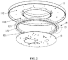
- the bottom surface of the faceplate 11 has a supporting plate 112 disposed thereon.
- the supporting plate 112 has a shape of ring.
- the shape of the supporting plate 112 is corresponding to the shape of the faceplate 11.
- the supporting plate 112 is used for enhancing the strength and the bearing capacity of the faceplate 11, such that the supporting plate 112 may deform under the pressure of an increased number of the medical probes 21.
- the fixing plate 12 is a circular slab.
- the fixing plate 12 is provided with respect to the through hole 111 of the faceplate 11.
- the center region of the fixing plate 12 is provided with an assembly mounting region.
- the components comprise a main control board of an ultrasonic equipment, a management circuit board of the medical probe 21, and motherboard of a monitor and other equipments.
- the medical probe holding table 10 for holding medical probes further comprises a turntable 15.
- the turntable 15 is positioned between the faceplate 11 and the fixing plate 12 and rotatably connects the faceplate 11 to the fixing plate 12.
- the turntable 15 comprises a first ring 151 and a second ring 152.
- a radius of the first ring 151 is larger than that of the second ring 152, and the first ring 151 is positioned on the outside of the second ring 152.
- the first ring 151 and the second ring 152 are concentric rings.
- the first ring 151 is rotatablely connected to the second ring 152.
- the first ring 151 and the second ring 152 may be rotated about a common center axis respectively without interfering with each other. So that the faceplate 11 and the fixing plate 12 may be rotated about the common center axis respectively without interfering with each other.
- the first ring 151 is fixedly connected to the faceplate 11, and the second ring 152 is fixedly connected to the fixing plate 12.
- the first ring 151 is fixedly connected to the supporting plate 112 of the faceplate 11.
- the first ring 151 may be fastened to the supporting plate 112 via screws
- the second ring 152 may be fastened to the fixing plate 12 via screws.
- the supporting plate 112 may have a first locating pin 113 disposed thereon
- the fixing plate 12 may have a second locating pin 121 disposed on.
- the first ring 151 and the second ring 152 each respectively defines a locating hole (not shown).
- the locating hole of the first ring 151 is correspondingly connected to the first locating pin 113, and the locating hole of the second ring 152 is correspondingly connected to the second locating pin 121, so as to perform positiong of the supporting plate 112 and the fixing plate 12 with respect to each other when they are connected to different the rings on the turntable 15.
- There are pluralities of the first locating pins 113, the second locating pins 121, and, correspondingly, the positiong holes are evenly diposed, so as to ensure the first ring 151 is concentric with the faceplate 11, the second ring 152 is concentric with the fixing plate 12, thereby the turntable 15 may be steadily rotated with the faceplate 11 and the fixing plate 12 without displacement.
- the first ring 151 may be fixedly connected to the fixing plate 12, and the second ring 152 may be fixedly connected to the supporting plate 112 of the faceplate 11.
- the fixing plate 12 and the faceplate 11 may be rotated with respect to each other.
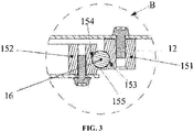
- a first groove 153 and a second groove 154 are disposed on adjacent sides of the first ring 151 and the second ring 152, respectively.
- Rolls 16 are disposed between the first groove 153 and the second groove 154. That is, the first groove 153 is defined in an internal sidewall of the first ring 151, and the second groove 154 is defined in an outside sidewall of the second ring 152.
- the first groove 153 and the second groove 154 each has a cross section of a semi-circular groove.
- the first groove 153 and the second groove 154 are disposed opposite to each other, so as to form a channel having a cross section of round.
- the rolls 16, being disposed between the first groove 153 and the second groove 154, may roll along the channel.
- the rolls 16 may roll in the channel to reduce a frictional force between the first ring 151 and the second ring 152.
- the first groove 153 is located at a lower position in a middle portion of the internal sidewall of the first ring 151, and the second groove 154 is locateded at a middle position of the outside sidewall of the second ring 152.
- the first ring 151 and the second ring 152 may be partially displaced up and down, such that the first ring 151, being slightly higher than the second ring 152, may be conveniently connected to the faceplate 11, and the second ring 152 which is slightly lower may be conveniently connected to the fixing plate 12.
- a spacing plate 155 pionting to the second ring 152 may be disposed in the bottom of the first ring 151. The spacing plate 155 may avoid the rolls 16 from rolling out. The rolls 16 may be balls.
- first ring 151 and the second ring 152 may be stacked with a same axial.
- the ring located on the upper is fixedly connected to the faceplate 11, and the ring located on the down is fixedly connected to the fixing plate 12.
- grooves may be formed in the opposide sides of the first ring 151 and f the second ring 152, and the rolls may roll along the grooves. In this way, it is also possible to make the faceplate 11 and the fixing plate 12 rotate with respect to each other without interfering with each other.
- circular electric conductive rails 17 are disposed on the inner sidewall of the through hole 111 of the faceplate 11.
- Conductive components 18 are fixedly arranged on the fixing plate 12.
- the fixing plate 12 may be fastened to the bottoms of the conductive components 18 via screw, clamping, or welding.
- the conductive components 18 may be electrically connected to an external power.
- the conductive components 18 may be electrically connected to the conductive rails 17 which are electrically connected to the probe placement unit 14, so the probe placement unit 14 may be electrically connected to the external power.
- the plurality of the conductive components 18 may be evenly diposed on the the fixing plate 12. That is, the conductive components 18 are evenly diposed with respect to the conductive rails 17.
- the conductive components 18 may keep the electrical connection between the conductive components 18 and the conductive rails 17, so as to avoid break of the whole circuit due to a single damaged conductive component 18.
- a fixing mount 115 for fixing the conductive rails 17 is disposed on the inner sidewall of the through hole 111, and the conductive rails 17 are embeded in the fixing mount 115.
- the conductive rails 17 may be embeded in the fixing mount 115 by assembling and injection molding.
- some clamps or climps for fixing the conductive rails 17 may be disposed on the inner sidewall of the fixing mount 115, such that the fixing mount 115 may be snaped to the conductive rails 17 by clamping or climping.
- each conductive component 18 comprises a base 181 fixed onto the fixing plate 12 and an electric conductive connector 182.
- the conductive connector 182 is connected to the base 181 by a connecting rod 183, and the conductive connector 182 is electrically connected to one of the conductive rails 17.
- An elastic member 184 is sleeved on the connecting rod 183.
- the conductive connector 182 may have a relative elastic displacement in a radial direction of the conductive rails 17 by the elastic member 184 and the base 181.
- the extention direction of the elastic member 184 directs to the corresponding conductive rail 17.
- the conductive connector 182 may have a relative elastic displacement in a radial direction of the corresponding conductive rail 17 by the elastic member 184 and the base 181.
- the conductive connector 182 may be reliably connected to the inner sidewall of the conductive rail 17 under the elastic force of the elastic member 184, so as to achieve reliable conductivity.
- each conductive component 18 comprises a base 181 and a conductive connector 182.
- the base 181 is fixed to the fixing plate 12.
- the base 181 comprises a bottom portion 185 fixedly connected to the fixing plate 12 and a supporting portion 186 fixedly connected to the bottom portion 185.
- a sleeve 187 is sleeved on the supporting portion 186. An opening end of the sleeve 187 directs to the conductive rails 17, and the opposite end is closed (closed end).
- the conductive connector 182 is connected to the base 181 by the connecting rod 183 extending in the radial direction of the corresponding conductive rail 17.
- the conductive connector 182 is electrically connected to the conductive rail 17.
- Each of the conductive component 18 further comprises a spacing element 188.
- An end of the connecting rod 183 away the conductive connector 182 passes the sleeve 187 and is snapped to the spacing element.
- the spacing element 188 may be a retaining ring, and an end of the connecting rod 183 away from the conductive connector 182 has a clamping slot. The retaining ring may be snapped onto the clamping slot.
- the elastic member 184 is sleeved on the connecting rod 183, and the connecting rod 183 and the elastic member 184 are bothreceived in the sleeve 187.
- the ends of the elastic member 184 respectively abut on the conductive connector and the closed end of the sleeve 187.
- the elastic member 184 may be a spring, a spring washer or other resilient material having extensibiity.
- the elastic member 184 is provided to abut on the corresponding conductive connector 182 and the base 181, such that the conductive connector 182 is prevented from being in rigid contact with the conductive connector 182, which may result in an unadjustable pressureon the conductive rails 17.
- the elastic force of the elastic member 184 may cause the conductive connector 182 to stably contact with the conductive rails 17 and there is still a certain space for displacement/deformation.
- each conductive connector 182 comprises an electric conductive roller 1821, a holder 1822 and a shaft 1823.
- the conductive roller 1821 is rotatably disposed on the holder 1822 by the shaft 1823.
- the holder 1822 is connected to a corresponding connecting rod 183.
- the conductive roller 1821 is in electric communication with the conductive rails 17.
- the faceplate 11 may drive the conductive rails 17 to rotate, and roating of the conductive rails 17 may drive the conductive roller 1821 to roll. Since the friction between the conductive rails 17 and the conductive roller 1821 is rolling friction, wearing of the parts is significantly reduced, thereby the reliability of the product is enhanced.
- a plurality of sleeves 187 are disposed on the the supporting portion of base 181.
- Each sleeve 187 is corresponding to mounting of one connecting rod 183, one elastic member 184, and one conductive connector 182.
- a plurality of conductive rails 17 are provided, and each of the conductive connectors 182 is electrically connected to one corresponding conductive rail 17.
- At least two conductive rails 17 are provided.
- Each of the conductive components 18 is provided with a corresponding number of the conductive connectors 182 connected the conductive rails 17.
- a plurality of sets of power supply components may be provided to cooperate with the conductive rails 17 at different angles, so that two or even mor power supply circuits can be formed between the faceplate 11 and the fixing plate 12 to meet the requirement of power if a different number of medical probes 21 are provided on the faceplate 11.
- the conductive connector 182 of the conductive component 18 may be an electric brush passing the base 181.
- the elastic member 184 is placed between and abut on the electric brush and the base 181.
- the elastic force of the elastic member 184 may force the electric brush and the conductive rails 17 to elastically displace with respect to each other in the radial direction of the conductive rails 17 when the electric brush is slidably connected to the conductive rails 17.
- the structure of the electric brush may include, but is not limited to, a filament, a plate and so on.
- each connecting rod 183 away the conductive connector has a terminal disposed thereon (no shown).
- Lugs 117 are disposed on the side of the fixing mount 115 opposite to the conductive rails.
- the lugs 117 are electrically connected to the conductive rails 17.
- the terminals and the lugs 117 may facilitate electrical connecting of the wires 40 and the connecting rods 183 to the conductive rails 17, thus facilitating wiring of the medical equipment.
- the medical equipment provided in the disclosure further comprises a frame 30.
- the medical probe holding table 10 for holding medical probes may be placed on the frame 30, so as to facilitate movement of the medical probe holding table 10 for holding medical probes.
Landscapes
- Health & Medical Sciences (AREA)
- Life Sciences & Earth Sciences (AREA)
- Surgery (AREA)
- General Health & Medical Sciences (AREA)
- Public Health (AREA)
- Engineering & Computer Science (AREA)
- Biomedical Technology (AREA)
- Heart & Thoracic Surgery (AREA)
- Medical Informatics (AREA)
- Molecular Biology (AREA)
- Veterinary Medicine (AREA)
- Animal Behavior & Ethology (AREA)
- Nuclear Medicine, Radiotherapy & Molecular Imaging (AREA)
- Physics & Mathematics (AREA)
- Pathology (AREA)
- Biophysics (AREA)
- Radiology & Medical Imaging (AREA)
- Accommodation For Nursing Or Treatment Tables (AREA)
Description
- The present disclosure relates generally to medical instruments, and more specifically to a medical probe holding table for holding medical probes.
- A fetal heart monitoring equipment often monitors several pregnant women at the same time, so the equipment must be equipped with a plurality of medical probes. Accordingly, it is important to place the medical probes at positions easily accessible for medical staff. At present, medical probes are disposed on a top or sides of a medical equipment. According to the traditional way of disposing medical probes, the medical probes can not be moved, and when there are many medical probes they would overlay each other, therefore, the medical staff still cannot easily to take the medical probes. It is not easy to change the number of the medical probes, if more medical probes are used, it would be difficult for a user to take and place the medical probes.
- In order to overcome the shortcomings mentioned above, the disclosure provides a medical probe holding table for holding medical probes. In the medical probe holding table, positions of the medical probes may be changed.
- In order to solve the technical problems, the disclosure is as follows:
A medical probe holding table for holding medical probes comprising: a faceplate; a first ring; a second ring; and a fixing plate supporting the faceplate, wherein the first ring is rotably connected to the second ring, wherein one of the first ring and the second ring is fixedly connected to the faceplate, and the other is fixedly connected to the fixing plate, and wherein the faceplate is rotatably connected to the fixing plate, a plurality of probe placement units for installing medical probes are disposed on the faceplate, and each of the probe placement units is in electrical communication with an external power. - Further, each of the probe placement units may comprise a socket electrically connected to a corresponding medical probe and a probe slot receiving the medical probe.
- According to the present invention, the medical probe holding table for holding medical probes comprises a first ring and a second ring. The first ring is rotatablely connected to the second ring, and one of the first ring and the second ring is fixedly connected to the faceplate, and the other one is fixedly connected to the fixing plate.
- Further, the first ring may be sleeved on outside of the second ring, and the first ring and the second ring may be concentric rings.
- Further, a first groove and a second groove may be respectively disposed on adjacent sides of the first and second rings, and rolls may be disposed between the first and second grooves.
- Further, the faceplate may have a supporting plate disposed thereon. Moreover, the supporting plate may have a shape of ring, and the supporting plate may be disposed on a lower surface of the faceplate.
- Further, the supporting plate may have a first locating pin disposed thereon, and the fixing plate may have a second locating pin disposed thereon. Moreover, a locating hole in one of the first and second rings may be correspondingly connected to the first locating pin, and a locating hole in the other one of the first and second rings may be correspondingly connected to the second locating pin.
- Further, one of the first and second rings may be fastened to the supporting plate by screws, and the other one of the first and second rings may be fastened to the fixing plate by screws.
- Further, a through hole may be formed in the middle of the faceplate, circular conductive rails may be disposed on an inner sidewall of the through hole, the conductive components may be fixedly arranged on the fixing plate, and the conductive components may be electrically connected to the conductive rails, and the probe placement unit may be electrically connected to the conductive rails.
- Further, the conductive components may be evenly disposed on the the fixing plate.
- Further, a fixing mount for fixing the conductive rails may be disposed on the inner sidewall of the through hole, and the conductive rails may be embedded in the fixing mount.
- Further, the fixing mount may be snapped to the conductive rails.
- Further, lugs may be disposed on a side of the fixing mount opposite to the conductive rails, and the lugs may be electrically connected to the conductive rails.
- Further, each of the conductive components may comprise a base and a conductive connector. Moreover, the base may be fixed onto the fixing plate, and the conductive connector may be connected to the base by a connecting rod, the connecting rod may extend in a radial direction of the conductive rails, the conductive connector may be conductive connected to the conductive rails, and an elastic member may be sleeved on the connecting rod, and the elastic member may be compressed between the conductive connector and the conductive rails.
- Further, the base may comprise a bottom portion fixedly connected to the fixing plate and a supporting portion fixedly connected to the bottom portion, a sleeve may be disposed on the supporting portion, an opening end of the sleeve may direct to the conductive rails, and an opposite end of the sleeve may be closed, and the connecting rod and the elastic member may both be received in the sleeve, and both ends of the elastic member respectively may abut on the conductive connector and the closed end of the sleeve.
- Further, a plurality of sleeves may be disposed on the supporting portion of the base, and each of the sleeves may correspond to mounting of one connecting rod, one elastic member, and one conductive connector, and each of the conductive connectors may be electrically connected to a corresponding one of the conductive rails.
- Further, each of the conductive components may comprise a spacing element, and an end of the connecting rod away from the conductive connector may pass through from the closed end of the sleeve to be snapped to the spacing element.
- Further, the spacing element may be a retaining ring, and an end of the connecting rod away from the conductive connector may have a clamping slot. Moreover, the retaining ring may be snapped to the retaining ring.
- Further, the conductive connector may comprise a conductive roller, a holder, and a shaft. Moreover, the conductive roller may be rotatably disposed on the holder by the shaft, the holder may be connected to the connecting rod, and the conductive roller may be in electrical communication with the conductive rails
- Further, an end of the connecting rod away the conductive connector may have a terminal disposed thereon
- Further, a medical equipment is provided. The medical equipment comprises a medical probe holding table for holding medical probes and a plurality of power consumption units.
- Further, the medical probe holding table for holding medical probes comprises: a faceplate; a first ring; a second ring; and a fixing plate supporting the faceplate, wherein the first ring is rotably connected to the second ring, wherein one of the first ring and the second ring is fixedly connected to the faceplate, and the other is fixedly connected to the fixing plate, and wherein the faceplate, a plurality of probe placement units for installing medical probes are disposed on the faceplate, and each of the probe placement units is in electrical communication with an external power.
- Further, in this embodiment the power consumption units are circularly disposed on the faceplate, and each of the power consumption units is electrically connected to the medical probe holding table for holding medical probes.
-
CN 203122359 U discloses a device for fetal monitoring suitable for holding medical probes. Compared with the related art, in the medical probe holding table for holding medical probes according to the present invention, the faceplate is rotatably connected to the fixing plate. That is, the medical probes are installed on the rotatably faceplate, and every probe placement unit may ensure electrical communication with the external power. Therefore, the medical staff can arbitrarily use any of the medical probes on the probe placement unit by rotatating the faceplate to make the medical probe face to the patient, and avoid stacking of the medical probes. So it is easy for the medical staff to distinguish and pick up these medical probes. The medical staff can arbitrarily use any of the medical probes on the faceplate, operation is facilitated and wroking efficiency is increased accordingly. - The medical equipment of using the same also has advantages of the above.
-
-
Fig. 1 is a perspective view showing the medical probe holding table for holding medical probes of an embodiment of the disclosure. -
Fig. 2 is a bottom view showing the medical probe holding table for holding medical probes ofFig. 1 . -
Fig. 3 is a cross section view showing a part B of the medical probe holding table for holding medical probes ofFig. 2 . -
Fig. 4 is a perspective view showing the medical probe holding table for holding medical probes of another embodiment of the disclosure. -
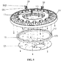
Fig. 5 is a perspective exploded view showing the medical probe holding table for holding medical probes ofFig. 4 . -
Fig. 6 . is a sectional view showing the medical probe holding table for holding medical probes ofFig. 4 . -
Fig. 7 is a partial magnification view showing a part A of the medical probe holding table for holding medical probes ofFig. 4 . -
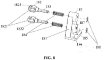
Fig. 8 is a perspective exploded view showing a conductive component of the medical probe holding table for holding medical probes ofFig. 4 . -
Fig. 9 is a perspective exploded view showing the conductive connector of the conductive component ofFig. 8 . -
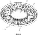
Fig. 10 is a bottom view showing the medical probe holding table for holding medical probes ofFig. 4 . -
- 10-medical probe holding table for holding medical probes;
- 11-faceplate;
- 111-through hole;
- 112; supporting plate;
- 113: first locating pin;
- 115: fixing mount;
- 12: fixing plate;
- 121: second locating pin;
- 14: probe placement unit;
- 15: turntable;
- 151: first ring;
- 152: second ring;
- 153: first groove;
- 154: second groove;
- 155: spacing plate;
- 16: roll;
- 17: conductive rail;
- 18: conductive component;
- 181: base;
- 182: conductive connector;
- 1821: conductive roller;
- 1822: holder;
- 1823: shaft;
- 183: connecting rod;
- 184: elastic member;
- 185: bottom portion;
- 186: supporting portion;
- 187: sleeve;
- 188: spacing element;
- 20: power consumption unit;
- 21: medical probe;
- 30: frame; and
- 40: wire
- Embodiments of the disclosure will now be described in detail. It may be understand that the disclosure may be varied in different embodiments without departing the scope of the disclosure. Hereinafter, the disclosure will be explained with reference to the accompanying drawings. By means of the drawings the essentially means of the disclosure shall be illustrated, rather than to limit the disclosure.
- The disclosure provides a medical equipment. The medical equipment comprises a medical probe holding table 10 for holding medical probes and a plurality of
power consumption units 20. Thepower consumption units 20 are circularly disposed on a faceplate, and each of thepower consumption units 20 is electrically connected to the medical probe holding table for holding medical probes. As shown inFig. 1 , a plurality ofmedical probes 21 may be disposed in the medical probe holding table 10 for holding medical probes via a plurality of probe placement units. The probe placement units are used for installing the medical probes. It may be understood that the probe placement unit may be used for other parallelpower consumption units 20. In this embodiment, themedical probe 21 is just an example, and others are omitted for sake of simplicity. - According to the invention, the medical probe holding table 10 for holding medical probes comprises a
faceplate 11 and a fixingplate 12 for supporting thefaceplate 11. Thefaceplate 11 is rotatably connected to the fixingplate 12. A plurality of probe placement units for installingmedical probes 21 are disposed on thefaceplate 11, and each of theprobe placement units 14 is electrically connected to an external power. - The
faceplate 11 is rotatably connected to the fixingplate 12 in the medical probe holding table 10 for holding medical probes of the disclosure. The medical probes are disposed on the rotatable faceplate. Everyprobe placement unit 14 is electrically connected to the external power reliably. The medical staff can select any one of themedical probes 21 on theprobe placement unit 14 according to their requirement, and align themedical probe 21 to the patient by rotatating thefaceplate 11, such as to avoid stacking of the plurality ofmedical probes 21. Therefore, the medical staff may easily distinguish and move these medical probes. Since the medical staff can arbitrarily use anymedical probe 21 on thefaceplate 11, operation is facilitated and operation efficiency is increased. - The
faceplate 11 may comprise a circular structure with a throughhole 111 formed in the middle thereof. A plurality ofprobe placement units 14 may be disposed on a circular upper surface of the faceplate. Theprobe placement units 14 may be evenly diposed on the circular surface of thefaceplate 11, so as to arrange themedical probes 21 as more as possible and expand the capacity of thefaceplate 11 for receiving the medical probes 21. In addition, the circular surface of thefaceplate 11 may be arched, that is, theprobe placement units 14 are disposed on the arched and raised upper surface of thefaceplate 11, so as to facilitate to take the medical probes 21. - As shown in
Fig. 4 , each of theprobe placement units 14 may comprise asocket 141 electrically connected to one of themedical probes 21 and aprobe slot 142 receiving themedical probe 21. It may be understood that themedical probe 21 may include one or more rechargeable batteries, and thesocket 141 may be a rechargeable fixed socket which may recharge the rechargeable battery. Thesocket 141 may have an elastic clip disposed thereon for fixing themedical probe 21. Theprobe slot 142 is used for retractably receiving themedical probe 21. When themedical probe 21 is used, themedical probe 21 is pulled out from theprobe slot 142, and after used, themedical probe 21 may be automatically retracted back to theprobe slot 142. - In the embodiment shown in
Fig. 2 , the bottom surface of thefaceplate 11 has a supportingplate 112 disposed thereon. The supportingplate 112 has a shape of ring. The shape of the supportingplate 112 is corresponding to the shape of thefaceplate 11. The supportingplate 112 is used for enhancing the strength and the bearing capacity of thefaceplate 11, such that the supportingplate 112 may deform under the pressure of an increased number of the medical probes 21. - The fixing
plate 12 is a circular slab. The fixingplate 12 is provided with respect to the throughhole 111 of thefaceplate 11. The center region of the fixingplate 12 is provided with an assembly mounting region. The components comprise a main control board of an ultrasonic equipment, a management circuit board of themedical probe 21, and motherboard of a monitor and other equipments. When the fixingplate 12 is positioned on the work table for the medical staff, thefaceplate 11 on which the plurality of medical probes are placed can be fixed, so as to facilitate the medical staff to take and place the medical probes 21. - In the specific embodiment, the medical probe holding table 10 for holding medical probes further comprises a
turntable 15. Theturntable 15 is positioned between thefaceplate 11 and the fixingplate 12 and rotatably connects thefaceplate 11 to the fixingplate 12. Specifically, as shown inFig. 3 , theturntable 15 comprises afirst ring 151 and asecond ring 152. A radius of thefirst ring 151 is larger than that of thesecond ring 152, and thefirst ring 151 is positioned on the outside of thesecond ring 152. Thefirst ring 151 and thesecond ring 152 are concentric rings. Thefirst ring 151 is rotatablely connected to thesecond ring 152. Thefirst ring 151 and thesecond ring 152 may be rotated about a common center axis respectively without interfering with each other. So that thefaceplate 11 and the fixingplate 12 may be rotated about the common center axis respectively without interfering with each other. - In the specific embodiment, the
first ring 151 is fixedly connected to thefaceplate 11, and thesecond ring 152 is fixedly connected to the fixingplate 12. Specifically, thefirst ring 151 is fixedly connected to the supportingplate 112 of thefaceplate 11. Thefirst ring 151 may be fastened to the supportingplate 112 via screws, and thesecond ring 152 may be fastened to the fixingplate 12 via screws. Moreover, the supportingplate 112 may have afirst locating pin 113 disposed thereon, and the fixingplate 12 may have asecond locating pin 121 disposed on. Thefirst ring 151 and thesecond ring 152 each respectively defines a locating hole (not shown). The locating hole of thefirst ring 151 is correspondingly connected to thefirst locating pin 113, and the locating hole of thesecond ring 152 is correspondingly connected to thesecond locating pin 121, so as to perform positiong of the supportingplate 112 and the fixingplate 12 with respect to each other when they are connected to different the rings on theturntable 15. There are pluralities of the first locating pins 113, the second locating pins 121, and, correspondingly, the positiong holes are evenly diposed, so as to ensure thefirst ring 151 is concentric with thefaceplate 11, thesecond ring 152 is concentric with the fixingplate 12, thereby theturntable 15 may be steadily rotated with thefaceplate 11 and the fixingplate 12 without displacement. - In other embodiments, the
first ring 151 may be fixedly connected to the fixingplate 12, and thesecond ring 152 may be fixedly connected to the supportingplate 112 of thefaceplate 11. As long as thefirst ring 151 and thesecond ring 152 are fixedly connected to the fixingplate 12 and thefaceplate 11, respectively, and thefirst ring 151 and thesecond ring 152 may be rotated with respect to each other, the fixingplate 12 and thefaceplate 11 may be rotated with respect to each other. - As shown in
Fig. 3 , in a further embodiment, afirst groove 153 and asecond groove 154 are disposed on adjacent sides of thefirst ring 151 and thesecond ring 152, respectively.Rolls 16 are disposed between thefirst groove 153 and thesecond groove 154. That is, thefirst groove 153 is defined in an internal sidewall of thefirst ring 151, and thesecond groove 154 is defined in an outside sidewall of thesecond ring 152. Thefirst groove 153 and thesecond groove 154 each has a cross section of a semi-circular groove. Moreover, thefirst groove 153 and thesecond groove 154 are disposed opposite to each other, so as to form a channel having a cross section of round. Therolls 16, being disposed between thefirst groove 153 and thesecond groove 154, may roll along the channel. When thefirst ring 151 and thesecond ring 152 are rotated with respect to each other, therolls 16 may roll in the channel to reduce a frictional force between thefirst ring 151 and thesecond ring 152. - In one embodiment, the
first groove 153 is located at a lower position in a middle portion of the internal sidewall of thefirst ring 151, and thesecond groove 154 is locateded at a middle position of the outside sidewall of thesecond ring 152. When thefirst ring 151 is sleeved on the outside of thesecond ring 152 and the first and second grooves are opposite to each other, thefirst ring 151 and thesecond ring 152 may be partially displaced up and down, such that thefirst ring 151, being slightly higher than thesecond ring 152, may be conveniently connected to thefaceplate 11, and thesecond ring 152 which is slightly lower may be conveniently connected to the fixingplate 12. Aspacing plate 155 pionting to thesecond ring 152 may be disposed in the bottom of thefirst ring 151. Thespacing plate 155 may avoid therolls 16 from rolling out. Therolls 16 may be balls. - In other embodiments, the
first ring 151 and thesecond ring 152 may be stacked with a same axial. The ring located on the upper is fixedly connected to thefaceplate 11, and the ring located on the down is fixedly connected to the fixingplate 12. In addition, in the stacked structure, grooves may be formed in the opposide sides of thefirst ring 151 and f thesecond ring 152, and the rolls may roll along the grooves. In this way, it is also possible to make thefaceplate 11 and the fixingplate 12 rotate with respect to each other without interfering with each other. - As shown in
Figs. 4 and5 , in one embodiment, circular electricconductive rails 17 are disposed on the inner sidewall of the throughhole 111 of thefaceplate 11.Conductive components 18 are fixedly arranged on the fixingplate 12. The fixingplate 12 may be fastened to the bottoms of theconductive components 18 via screw, clamping, or welding. - The
conductive components 18 may be electrically connected to an external power. Theconductive components 18 may be electrically connected to theconductive rails 17 which are electrically connected to theprobe placement unit 14, so theprobe placement unit 14 may be electrically connected to the external power. Moreover, the plurality of theconductive components 18 may be evenly diposed on the the fixingplate 12. That is, theconductive components 18 are evenly diposed with respect to the conductive rails 17. Theconductive components 18 may keep the electrical connection between theconductive components 18 and theconductive rails 17, so as to avoid break of the whole circuit due to a single damagedconductive component 18. - As shown in
Figs. 6 and7 , in one embodiment, a fixingmount 115 for fixing theconductive rails 17 is disposed on the inner sidewall of the throughhole 111, and theconductive rails 17 are embeded in the fixingmount 115. Theconductive rails 17 may be embeded in the fixingmount 115 by assembling and injection molding. In the specific embodiment, some clamps or climps for fixing theconductive rails 17 may be disposed on the inner sidewall of the fixingmount 115, such that the fixingmount 115 may be snaped to theconductive rails 17 by clamping or climping. - In the specific embodiment, each
conductive component 18 comprises a base 181 fixed onto the fixingplate 12 and an electricconductive connector 182. Theconductive connector 182 is connected to thebase 181 by a connectingrod 183, and theconductive connector 182 is electrically connected to one of the conductive rails 17. Anelastic member 184 is sleeved on the connectingrod 183. Theconductive connector 182 may have a relative elastic displacement in a radial direction of theconductive rails 17 by theelastic member 184 and thebase 181. The extention direction of theelastic member 184 directs to the correspondingconductive rail 17. Theconductive connector 182 may have a relative elastic displacement in a radial direction of the correspondingconductive rail 17 by theelastic member 184 and thebase 181. Theconductive connector 182 may be reliably connected to the inner sidewall of theconductive rail 17 under the elastic force of theelastic member 184, so as to achieve reliable conductivity. - As shown in
Fig. 8 , in the specific embodiment, eachconductive component 18 comprises abase 181 and aconductive connector 182. Thebase 181 is fixed to the fixingplate 12. Thebase 181 comprises abottom portion 185 fixedly connected to the fixingplate 12 and a supportingportion 186 fixedly connected to thebottom portion 185. Asleeve 187 is sleeved on the supportingportion 186. An opening end of thesleeve 187 directs to theconductive rails 17, and the opposite end is closed (closed end). - The
conductive connector 182 is connected to thebase 181 by the connectingrod 183 extending in the radial direction of the correspondingconductive rail 17. Theconductive connector 182 is electrically connected to theconductive rail 17. Each of theconductive component 18 further comprises aspacing element 188. An end of the connectingrod 183 away theconductive connector 182 passes thesleeve 187 and is snapped to the spacing element. Specifically, thespacing element 188 may be a retaining ring, and an end of the connectingrod 183 away from theconductive connector 182 has a clamping slot. The retaining ring may be snapped onto the clamping slot. - The
elastic member 184 is sleeved on the connectingrod 183, and the connectingrod 183 and theelastic member 184 are bothreceived in thesleeve 187. The ends of theelastic member 184 respectively abut on the conductive connector and the closed end of thesleeve 187. It may be appreciated, theelastic member 184 may be a spring, a spring washer or other resilient material having extensibiity. - In each
conductive component 18, theelastic member 184 is provided to abut on the correspondingconductive connector 182 and thebase 181, such that theconductive connector 182 is prevented from being in rigid contact with theconductive connector 182, which may result in an unadjustable pressureon the conductive rails 17. When the direction of extension of theelastic member 184 is directed to theconductive rails 17, the elastic force of theelastic member 184 may cause theconductive connector 182 to stably contact with theconductive rails 17 and there is still a certain space for displacement/deformation. When thefaceplate 11 drives theconductive rails 17 to rotate, it is difficult to ensure that the movement path of theconductive rails 17 is a perfect circular shape, however, a deformation resulted from this may be offseted by the contraction of theelastic member 184 abutting on theconductive connector 182, so that the relation rotation of thefaceplate 11 and the fixingplate 12 is smooth and the power supply between each other is stable. - As shown in
Fig. 9 , in the specific embodiment, eachconductive connector 182 comprises an electricconductive roller 1821, aholder 1822 and ashaft 1823. Theconductive roller 1821 is rotatably disposed on theholder 1822 by theshaft 1823. Theholder 1822 is connected to a corresponding connectingrod 183. Theconductive roller 1821 is in electric communication with the conductive rails 17. Thefaceplate 11 may drive theconductive rails 17 to rotate, and roating of theconductive rails 17 may drive theconductive roller 1821 to roll. Since the friction between theconductive rails 17 and theconductive roller 1821 is rolling friction, wearing of the parts is significantly reduced, thereby the reliability of the product is enhanced. - In the specific embodiment, a plurality of
sleeves 187 are disposed on the the supporting portion ofbase 181. Eachsleeve 187 is corresponding to mounting of one connectingrod 183, oneelastic member 184, and oneconductive connector 182. Moreover, a plurality ofconductive rails 17 are provided, and each of theconductive connectors 182 is electrically connected to one correspondingconductive rail 17. At least twoconductive rails 17 are provided. Each of theconductive components 18 is provided with a corresponding number of theconductive connectors 182 connected the conductive rails 17. Meanwhile, a plurality of sets of power supply components may be provided to cooperate with theconductive rails 17 at different angles, so that two or even mor power supply circuits can be formed between thefaceplate 11 and the fixingplate 12 to meet the requirement of power if a different number ofmedical probes 21 are provided on thefaceplate 11. - In other embodiments, it would be understood that the
conductive connector 182 of theconductive component 18 may be an electric brush passing thebase 181. Theelastic member 184 is placed between and abut on the electric brush and thebase 181. The elastic force of theelastic member 184 may force the electric brush and theconductive rails 17 to elastically displace with respect to each other in the radial direction of theconductive rails 17 when the electric brush is slidably connected to the conductive rails 17. The structure of the electric brush may include, but is not limited to, a filament, a plate and so on. - As shown in
Fig. 10 , in one embodiment, the end of each connectingrod 183 away the conductive connector has a terminal disposed thereon (no shown).Lugs 117 are disposed on the side of the fixingmount 115 opposite to the conductive rails. Thelugs 117 are electrically connected to the conductive rails 17. The terminals and thelugs 117 may facilitate electrical connecting of thewires 40 and the connectingrods 183 to theconductive rails 17, thus facilitating wiring of the medical equipment. - As shown in
Fig. 10 , in one embodiment, the medical equipment provided in the disclosure further comprises aframe 30. The medical probe holding table 10 for holding medical probes may be placed on theframe 30, so as to facilitate movement of the medical probe holding table 10 for holding medical probes. - The embodiments described above are merely some perefable ones, and the disclosure is not limited to any specific details of these embodiments. An ordinary person skilled in the art would readily appreciate that modifications or changes based on the principles of the disclosure. Accordingly, the scope of the invention should be limited solely by the appended claims.
Claims (20)
- A medical probe holding table (10) for holding medical probes, comprising:a faceplate (11);a first ring (151);a second ring (152); anda fixing plate (12) for supporting the faceplate (11),wherein the first ring (151) is rotatably connected to the second ring (152), whereinone of the first ring (151) and the second ring (152) is fixedly connected to the faceplate (11), and the other is fixedly connected to the fixing plate (12), andwherein the faceplate (11) is rotatably connected to the fixing plate (12), a plurality of probe placement units (14) for installing medical probes (21) are disposed on the faceplate (11), and each of the probe placement units (14) is in electrical communication with an external power.
- The medical probe holding table (10) according to claim 1, wherein each of the probe placement units (14) comprises: a socket (141) electrically connected to a corresponding medical probe (21), and a probe slot (142) receiving the medical probe (21).
- The medical probe holding table (10) according to claim 1, wherein the first ring (151) is sleeved outside of the second ring (152), and the first ring (151) and the second ring (152) are concentric rings.
- The medical probe holding table (10) according to claim 3, wherein a first groove (153) and a second groove (154) are respectively disposed on adjacent sides of the first ring (151) and the second ring (152), and rolls (16) are disposed between the first groove (153) and the second groove (154).
- The medical probe holding table (10) according to claim 1, wherein a supporting plate (112) is disposed on the faceplate (11) and has a shape of ring and is disposed on a lower surface of the faceplate (11).
- The medical probe holding table (10) according to claim 5, wherein a first locating pin (113) is disposed on the supporting plate (112) and a second locating pin (121) is disposed on the fixing plate (12), and
wherein a locating hole in one of the first (151) and second (152) rings is connected to the first locating pin (113), and a locating hole in the other of the first (151) and second (152) rings is connected to the second locating pin (121). - The medical probe holding table (10) according to claim 5, wherein one of the first (151) and second (152) rings is fastened to the supporting plate (112) by screws, and the other of the first (151) and second (152) rings is fastened to the fixing plate (12) by screws.
- The medical probe holding table (10) according to claim 1, wherein a through hole (111) is formed in the middle of the faceplate (11), a circular conductive rail (17) is disposed on an inner sidewall of the through hole (111),
wherein a conductive component (18) is fixedly arranged on the fixing plate (12), and
wherein the conductive component (18) is electrically connected to the conductive rail (17), and the probe placement unit (14) is electrically connected to the conductive rail (17). - The medical probe holding table (10) according to claim 8, wherein the conductive component (18) is disposed in a plurality and evenly disposed on the fixing plate (12).
- The medical probe holding table (10) according to claim 8, wherein a fixing mount (115) for fixing the conductive rails (17) is disposed on the inner sidewall of the through hole (111), and the conductive rails (17) are embedded in the fixing mount (115).
- The medical probe holding table (10) according to claim 10, wherein the fixing mount (115) is snapped to the conductive rail (17).
- The medical probe holding table (10) according to claim 10, wherein lugs (117) are disposed on a side of the fixing mount (115) opposite to the conductive rails (17) and electrically connected to the conductive rail (17).
- The medical probe holding table (10) according to claim 8, wherein the conductive component (18) comprises a base (181) and a conductive connector (182),
wherein the base (181) is fixed onto the fixing plate (12), and the conductive connector (182) is connected to the base (181) by a connecting rod (183),
wherein the connecting rod (183) extends in a radial direction of the conductive rail (17), and the conductive connector (182) is conductively connected to the conductive rail (17), and
wherein an elastic member (184) is sleeved on the connecting rod (183), and is compressed between the conductive connector (182) and the conductive rail (17). - The medical probe holding table (10) according to claim 13, wherein the base (181) comprises: a bottom portion (185) fixedly connected to the fixing plate (12); and a supporting portion (186) fixedly connected to the bottom portion (185),
wherein a sleeve (187) is disposed on the supporting portion (186), an opening end of the sleeve (187) directs to the conductive rails (17), and an opposite end of the sleeve (187) is closed, and
wherein the connecting rod (183) and the elastic member (184) are both received in the sleeve (187), and both ends of the elastic member (184) respectively abut on the conductive connector (182) and the closed end of the sleeve (187). - The medical probe holding table (10) according to claim 14, wherein a plurality of sleeves (187) are disposed on the supporting portion (186) of the base (181), and each of the sleeves (187) is corresponding to mounting of one connecting rod (183), one elastic member (184), and one conductive connector (182), and
wherein each of the conductive connectors (182) is electrically connected to one corresponding conductive rail (17). - The medical probe holding table (10) according to claim 13, wherein the conductive component (18) further comprises a spacing element (188), and an end of the connecting rod (183) away from the conductive connector (182) passes through the closed end of the sleeve (187) and is snapped to the spacing element (188).
- The medical probe holding table (10) according to claim 16, wherein the spacing element (188) is a retaining ring, and
wherein an end of the connecting rod (183) away from the conductive connector (182) has a clamping slot, and the retaining ring is snapped to the clamping slot. - The medical probe holding table (10) according to claim 13, wherein the conductive connector (182) comprises a conductive roller (1821), a holder (1822), and a shaft (1823), and
wherein the conductive roller (1821) is rotatably disposed on the holder (1822) by the shaft (1823), the holder (1822) is connected to the connecting rod (183), and the conductive roller (1821) is in electrical communication with the conductive rail (17). - The medical probe holding table (10) according to claim 13, wherein an end of the connecting rod (183) away the conductive connector (182) has a terminal disposed thereon.
- The medical probe holding table (10) according to claim 1, comprising
a plurality of power consumption units (20), circularly disposed on the faceplate (11), wherein each of the power consumption units (20) is electrically connected to the medical probe holding table (10).
Applications Claiming Priority (3)
| Application Number | Priority Date | Filing Date | Title |
|---|---|---|---|
| CN201620317840.5U CN205598015U (en) | 2016-04-15 | 2016-04-15 | Probe is placed platform and is adopted its platform truck |
| CN201620318233.0U CN205693117U (en) | 2016-04-15 | 2016-04-15 | Rotating disk electric power-feeding structure and use the armarium of this structure |
| PCT/CN2016/110712 WO2017177712A1 (en) | 2016-04-15 | 2016-12-19 | Probe placement table and medical equipment |
Publications (3)
| Publication Number | Publication Date |
|---|---|
| EP3248563A1 EP3248563A1 (en) | 2017-11-29 |
| EP3248563A4 EP3248563A4 (en) | 2018-10-03 |
| EP3248563B1 true EP3248563B1 (en) | 2020-04-29 |
Family
ID=60041375
Family Applications (1)
| Application Number | Title | Priority Date | Filing Date |
|---|---|---|---|
| EP16863198.4A Active EP3248563B1 (en) | 2016-04-15 | 2016-12-19 | Probe placement table and medical equipment |
Country Status (3)
| Country | Link |
|---|---|
| US (1) | US10512447B2 (en) |
| EP (1) | EP3248563B1 (en) |
| WO (1) | WO2017177712A1 (en) |
Families Citing this family (2)
| Publication number | Priority date | Publication date | Assignee | Title |
|---|---|---|---|---|
| US20190100275A1 (en) * | 2017-10-03 | 2019-04-04 | PalTorc, Inc. | Smart crank control for e-bike |
| CN116053873A (en) * | 2023-02-24 | 2023-05-02 | 深圳市默孚龙科技有限公司 | rolling slip ring |
Family Cites Families (19)
| Publication number | Priority date | Publication date | Assignee | Title |
|---|---|---|---|---|
| US3652972A (en) * | 1971-01-25 | 1972-03-28 | James W Kreider | Turntable device |
| US3794952A (en) * | 1972-09-26 | 1974-02-26 | J Dowis | Lazy susan assembly |
| US4046511A (en) * | 1975-06-16 | 1977-09-06 | Union Carbide Corporation | Pipettor apparatus |
| US4016511A (en) | 1975-12-19 | 1977-04-05 | The United States Of America As Represented By The Secretary Of The Air Force | Programmable variable length high speed digital delay line |
| US5178546A (en) | 1991-12-19 | 1993-01-12 | Itt Corporation | Contact apparatus for coupling terminals which move with respect to one another |
| CN2647261Y (en) | 2003-08-11 | 2004-10-13 | 英华 | Multifunction B type ultrasound probe cable holder |
| US7296775B2 (en) * | 2005-07-26 | 2007-11-20 | Mayer Peter L | Continuously rotatable electronic-device organizer |
| DE102005046465B4 (en) | 2005-09-22 | 2009-04-02 | Frank Hartwig | power distribution |
| TWI393309B (en) * | 2010-01-20 | 2013-04-11 | Powertech Ind Ltd | Reversable and concealable electrical power receptacle |
| CN201806784U (en) | 2010-10-15 | 2011-04-27 | 深圳市理邦精密仪器股份有限公司 | Probe rack structure |
| CN203122359U (en) | 2013-01-25 | 2013-08-14 | 深圳市理邦精密仪器股份有限公司 | Probe fixing structure and fetal monitoring device with probe fixing structure |
| US9054476B1 (en) * | 2013-06-10 | 2015-06-09 | Jason L. Reynolds | Rotary appliance base assembly |
| CN103607530A (en) | 2013-11-18 | 2014-02-26 | 徐州洞山果品科技开发有限公司 | A movable probe |
| CN204034030U (en) | 2014-07-16 | 2014-12-24 | 广州三瑞医疗器械有限公司 | Intapartum labo monitorin analgesic apparatus |
| CN204049874U (en) | 2014-09-03 | 2014-12-31 | 田云 | B ultrasonic specialty uses equipment display unit |
| CN204494332U (en) | 2015-03-30 | 2015-07-22 | 广州市锐鹰舞台设备有限公司 | A kind of rotary lamp frame |
| CN204863260U (en) | 2015-07-09 | 2015-12-16 | 宋文超 | Novel from brush B ultrasonic probe bracket |
| CN205693117U (en) | 2016-04-15 | 2016-11-16 | 深圳市理邦精密仪器股份有限公司 | Rotating disk electric power-feeding structure and use the armarium of this structure |
| CN205598015U (en) | 2016-04-15 | 2016-09-28 | 深圳市理邦精密仪器股份有限公司 | Probe is placed platform and is adopted its platform truck |
-
2016
- 2016-12-19 EP EP16863198.4A patent/EP3248563B1/en active Active
- 2016-12-19 US US15/528,326 patent/US10512447B2/en active Active
- 2016-12-19 WO PCT/CN2016/110712 patent/WO2017177712A1/en not_active Ceased
Non-Patent Citations (1)
| Title |
|---|
| None * |
Also Published As
| Publication number | Publication date |
|---|---|
| WO2017177712A1 (en) | 2017-10-19 |
| EP3248563A1 (en) | 2017-11-29 |
| US20180192992A1 (en) | 2018-07-12 |
| US10512447B2 (en) | 2019-12-24 |
| EP3248563A4 (en) | 2018-10-03 |
Similar Documents
| Publication | Publication Date | Title |
|---|---|---|
| US8096817B2 (en) | Rotatable and foldable electrical plug connector | |
| EP2615701A1 (en) | Power supply with detachable multi-directional plug | |
| US20130244462A1 (en) | Power socket and electrical connector assembly | |
| US7503779B1 (en) | Electronic device having foldable plug | |
| US10512447B2 (en) | Probe holding table and medical device | |
| KR20110120483A (en) | Terminal connection module and terminal connection device having the same | |
| CN102957034A (en) | Socket combination | |
| US20070026694A1 (en) | Continuously rotatable electronic-device organizer | |
| JP2010515057A5 (en) | ||
| CN104584336A (en) | Outlet unit facilitating plug separation, and multi-outlet device using same | |
| EP3846290A1 (en) | Wiring device for switch socket | |
| CN111817238A (en) | A plug-in box with a plug-in drive mechanism | |
| US11990780B2 (en) | Electronic device and charging foot seat thereof | |
| CN219436323U (en) | Plane slip ring, rotary conductive assembly and telescopic data line assembly | |
| US4713014A (en) | Quick-release multi-module terminating assembly | |
| CN110676661A (en) | a socket | |
| CN213093524U (en) | Rotatable plug | |
| CN110233402A (en) | Guide tracked removable wiring board | |
| CN205693117U (en) | Rotating disk electric power-feeding structure and use the armarium of this structure | |
| US9385495B1 (en) | Weight supporting slip ring | |
| CN120691192A (en) | Slip Ring Brush Holder | |
| CN210465608U (en) | Electronic board detection tool | |
| CN210779343U (en) | Socket | |
| KR20130129542A (en) | Battery connecting jig | |
| CN213484056U (en) | A plug-in UPS |
Legal Events
| Date | Code | Title | Description |
|---|---|---|---|
| STAA | Information on the status of an ep patent application or granted ep patent |
Free format text: STATUS: UNKNOWN |
|
| STAA | Information on the status of an ep patent application or granted ep patent |
Free format text: STATUS: THE INTERNATIONAL PUBLICATION HAS BEEN MADE |
|
| PUAI | Public reference made under article 153(3) epc to a published international application that has entered the european phase |
Free format text: ORIGINAL CODE: 0009012 |
|
| STAA | Information on the status of an ep patent application or granted ep patent |
Free format text: STATUS: REQUEST FOR EXAMINATION WAS MADE |
|
| 17P | Request for examination filed |
Effective date: 20170517 |
|
| AK | Designated contracting states |
Kind code of ref document: A1 Designated state(s): AL AT BE BG CH CY CZ DE DK EE ES FI FR GB GR HR HU IE IS IT LI LT LU LV MC MK MT NL NO PL PT RO RS SE SI SK SM TR |
|
| AX | Request for extension of the european patent |
Extension state: BA ME |
|
| RIN1 | Information on inventor provided before grant (corrected) |
Inventor name: WANG, GONGHUA Inventor name: WU, YONG Inventor name: GUO, CHUANXI Inventor name: YANG, KAI |
|
| A4 | Supplementary search report drawn up and despatched |
Effective date: 20180903 |
|
| RIC1 | Information provided on ipc code assigned before grant |
Ipc: A61B 50/15 20160101ALI20180827BHEP Ipc: H01R 35/04 20060101ALI20180827BHEP Ipc: A61B 50/24 20160101AFI20180827BHEP Ipc: A61B 50/30 20160101ALN20180827BHEP Ipc: H01R 39/08 20060101ALI20180827BHEP Ipc: H01R 39/28 20060101ALI20180827BHEP Ipc: A61B 50/20 20160101ALI20180827BHEP Ipc: A61B 5/0444 20060101ALN20180827BHEP Ipc: H01R 39/12 20060101ALI20180827BHEP |
|
| DAV | Request for validation of the european patent (deleted) | ||
| DAX | Request for extension of the european patent (deleted) | ||
| STAA | Information on the status of an ep patent application or granted ep patent |
Free format text: STATUS: EXAMINATION IS IN PROGRESS |
|
| 17Q | First examination report despatched |
Effective date: 20190814 |
|
| REG | Reference to a national code |
Ref country code: DE Ref legal event code: R079 Ref document number: 602016035391 Country of ref document: DE Free format text: PREVIOUS MAIN CLASS: A61B0050240000 Ipc: A61B0050200000 |
|
| GRAP | Despatch of communication of intention to grant a patent |
Free format text: ORIGINAL CODE: EPIDOSNIGR1 |
|
| RIC1 | Information provided on ipc code assigned before grant |
Ipc: A61B 5/0444 20060101ALN20191114BHEP Ipc: A61B 50/15 20160101ALI20191114BHEP Ipc: A61B 50/20 20160101AFI20191114BHEP Ipc: A61B 5/00 20060101ALN20191114BHEP Ipc: H01R 39/40 20060101ALN20191114BHEP Ipc: H01R 39/08 20060101ALN20191114BHEP Ipc: A61B 50/30 20160101ALN20191114BHEP |
|
| STAA | Information on the status of an ep patent application or granted ep patent |
Free format text: STATUS: GRANT OF PATENT IS INTENDED |
|
| INTG | Intention to grant announced |
Effective date: 20191219 |
|
| GRAS | Grant fee paid |
Free format text: ORIGINAL CODE: EPIDOSNIGR3 |
|
| GRAA | (expected) grant |
Free format text: ORIGINAL CODE: 0009210 |
|
| STAA | Information on the status of an ep patent application or granted ep patent |
Free format text: STATUS: THE PATENT HAS BEEN GRANTED |
|
| AK | Designated contracting states |
Kind code of ref document: B1 Designated state(s): AL AT BE BG CH CY CZ DE DK EE ES FI FR GB GR HR HU IE IS IT LI LT LU LV MC MK MT NL NO PL PT RO RS SE SI SK SM TR |
|
| REG | Reference to a national code |
Ref country code: GB Ref legal event code: FG4D |
|
| REG | Reference to a national code |
Ref country code: CH Ref legal event code: EP |
|
| REG | Reference to a national code |
Ref country code: DE Ref legal event code: R096 Ref document number: 602016035391 Country of ref document: DE |
|
| REG | Reference to a national code |
Ref country code: AT Ref legal event code: REF Ref document number: 1262181 Country of ref document: AT Kind code of ref document: T Effective date: 20200515 |
|
| REG | Reference to a national code |
Ref country code: IE Ref legal event code: FG4D |
|
| REG | Reference to a national code |
Ref country code: NL Ref legal event code: MP Effective date: 20200429 |
|
| REG | Reference to a national code |
Ref country code: LT Ref legal event code: MG4D |
|
| PG25 | Lapsed in a contracting state [announced via postgrant information from national office to epo] |
Ref country code: LT Free format text: LAPSE BECAUSE OF FAILURE TO SUBMIT A TRANSLATION OF THE DESCRIPTION OR TO PAY THE FEE WITHIN THE PRESCRIBED TIME-LIMIT Effective date: 20200429 Ref country code: GR Free format text: LAPSE BECAUSE OF FAILURE TO SUBMIT A TRANSLATION OF THE DESCRIPTION OR TO PAY THE FEE WITHIN THE PRESCRIBED TIME-LIMIT Effective date: 20200730 Ref country code: SE Free format text: LAPSE BECAUSE OF FAILURE TO SUBMIT A TRANSLATION OF THE DESCRIPTION OR TO PAY THE FEE WITHIN THE PRESCRIBED TIME-LIMIT Effective date: 20200429 Ref country code: FI Free format text: LAPSE BECAUSE OF FAILURE TO SUBMIT A TRANSLATION OF THE DESCRIPTION OR TO PAY THE FEE WITHIN THE PRESCRIBED TIME-LIMIT Effective date: 20200429 Ref country code: IS Free format text: LAPSE BECAUSE OF FAILURE TO SUBMIT A TRANSLATION OF THE DESCRIPTION OR TO PAY THE FEE WITHIN THE PRESCRIBED TIME-LIMIT Effective date: 20200829 Ref country code: PT Free format text: LAPSE BECAUSE OF FAILURE TO SUBMIT A TRANSLATION OF THE DESCRIPTION OR TO PAY THE FEE WITHIN THE PRESCRIBED TIME-LIMIT Effective date: 20200831 Ref country code: NO Free format text: LAPSE BECAUSE OF FAILURE TO SUBMIT A TRANSLATION OF THE DESCRIPTION OR TO PAY THE FEE WITHIN THE PRESCRIBED TIME-LIMIT Effective date: 20200729 |
|
| REG | Reference to a national code |
Ref country code: AT Ref legal event code: MK05 Ref document number: 1262181 Country of ref document: AT Kind code of ref document: T Effective date: 20200429 |
|
| PG25 | Lapsed in a contracting state [announced via postgrant information from national office to epo] |
Ref country code: RS Free format text: LAPSE BECAUSE OF FAILURE TO SUBMIT A TRANSLATION OF THE DESCRIPTION OR TO PAY THE FEE WITHIN THE PRESCRIBED TIME-LIMIT Effective date: 20200429 Ref country code: BG Free format text: LAPSE BECAUSE OF FAILURE TO SUBMIT A TRANSLATION OF THE DESCRIPTION OR TO PAY THE FEE WITHIN THE PRESCRIBED TIME-LIMIT Effective date: 20200729 Ref country code: LV Free format text: LAPSE BECAUSE OF FAILURE TO SUBMIT A TRANSLATION OF THE DESCRIPTION OR TO PAY THE FEE WITHIN THE PRESCRIBED TIME-LIMIT Effective date: 20200429 Ref country code: HR Free format text: LAPSE BECAUSE OF FAILURE TO SUBMIT A TRANSLATION OF THE DESCRIPTION OR TO PAY THE FEE WITHIN THE PRESCRIBED TIME-LIMIT Effective date: 20200429 |
|
| PG25 | Lapsed in a contracting state [announced via postgrant information from national office to epo] |
Ref country code: AL Free format text: LAPSE BECAUSE OF FAILURE TO SUBMIT A TRANSLATION OF THE DESCRIPTION OR TO PAY THE FEE WITHIN THE PRESCRIBED TIME-LIMIT Effective date: 20200429 Ref country code: NL Free format text: LAPSE BECAUSE OF FAILURE TO SUBMIT A TRANSLATION OF THE DESCRIPTION OR TO PAY THE FEE WITHIN THE PRESCRIBED TIME-LIMIT Effective date: 20200429 |
|
| PG25 | Lapsed in a contracting state [announced via postgrant information from national office to epo] |
Ref country code: CZ Free format text: LAPSE BECAUSE OF FAILURE TO SUBMIT A TRANSLATION OF THE DESCRIPTION OR TO PAY THE FEE WITHIN THE PRESCRIBED TIME-LIMIT Effective date: 20200429 Ref country code: RO Free format text: LAPSE BECAUSE OF FAILURE TO SUBMIT A TRANSLATION OF THE DESCRIPTION OR TO PAY THE FEE WITHIN THE PRESCRIBED TIME-LIMIT Effective date: 20200429 Ref country code: DK Free format text: LAPSE BECAUSE OF FAILURE TO SUBMIT A TRANSLATION OF THE DESCRIPTION OR TO PAY THE FEE WITHIN THE PRESCRIBED TIME-LIMIT Effective date: 20200429 Ref country code: IT Free format text: LAPSE BECAUSE OF FAILURE TO SUBMIT A TRANSLATION OF THE DESCRIPTION OR TO PAY THE FEE WITHIN THE PRESCRIBED TIME-LIMIT Effective date: 20200429 Ref country code: EE Free format text: LAPSE BECAUSE OF FAILURE TO SUBMIT A TRANSLATION OF THE DESCRIPTION OR TO PAY THE FEE WITHIN THE PRESCRIBED TIME-LIMIT Effective date: 20200429 Ref country code: SM Free format text: LAPSE BECAUSE OF FAILURE TO SUBMIT A TRANSLATION OF THE DESCRIPTION OR TO PAY THE FEE WITHIN THE PRESCRIBED TIME-LIMIT Effective date: 20200429 Ref country code: AT Free format text: LAPSE BECAUSE OF FAILURE TO SUBMIT A TRANSLATION OF THE DESCRIPTION OR TO PAY THE FEE WITHIN THE PRESCRIBED TIME-LIMIT Effective date: 20200429 Ref country code: ES Free format text: LAPSE BECAUSE OF FAILURE TO SUBMIT A TRANSLATION OF THE DESCRIPTION OR TO PAY THE FEE WITHIN THE PRESCRIBED TIME-LIMIT Effective date: 20200429 |
|
| REG | Reference to a national code |
Ref country code: DE Ref legal event code: R097 Ref document number: 602016035391 Country of ref document: DE |
|
| PG25 | Lapsed in a contracting state [announced via postgrant information from national office to epo] |
Ref country code: SK Free format text: LAPSE BECAUSE OF FAILURE TO SUBMIT A TRANSLATION OF THE DESCRIPTION OR TO PAY THE FEE WITHIN THE PRESCRIBED TIME-LIMIT Effective date: 20200429 Ref country code: PL Free format text: LAPSE BECAUSE OF FAILURE TO SUBMIT A TRANSLATION OF THE DESCRIPTION OR TO PAY THE FEE WITHIN THE PRESCRIBED TIME-LIMIT Effective date: 20200429 |
|
| PLBE | No opposition filed within time limit |
Free format text: ORIGINAL CODE: 0009261 |
|
| STAA | Information on the status of an ep patent application or granted ep patent |
Free format text: STATUS: NO OPPOSITION FILED WITHIN TIME LIMIT |
|
| 26N | No opposition filed |
Effective date: 20210201 |
|
| PG25 | Lapsed in a contracting state [announced via postgrant information from national office to epo] |
Ref country code: SI Free format text: LAPSE BECAUSE OF FAILURE TO SUBMIT A TRANSLATION OF THE DESCRIPTION OR TO PAY THE FEE WITHIN THE PRESCRIBED TIME-LIMIT Effective date: 20200429 |
|
| REG | Reference to a national code |
Ref country code: CH Ref legal event code: PL |
|
| PG25 | Lapsed in a contracting state [announced via postgrant information from national office to epo] |
Ref country code: MC Free format text: LAPSE BECAUSE OF FAILURE TO SUBMIT A TRANSLATION OF THE DESCRIPTION OR TO PAY THE FEE WITHIN THE PRESCRIBED TIME-LIMIT Effective date: 20200429 |
|
| REG | Reference to a national code |
Ref country code: BE Ref legal event code: MM Effective date: 20201231 |
|
| PG25 | Lapsed in a contracting state [announced via postgrant information from national office to epo] |
Ref country code: LU Free format text: LAPSE BECAUSE OF NON-PAYMENT OF DUE FEES Effective date: 20201219 Ref country code: IE Free format text: LAPSE BECAUSE OF NON-PAYMENT OF DUE FEES Effective date: 20201219 |
|
| PG25 | Lapsed in a contracting state [announced via postgrant information from national office to epo] |
Ref country code: CH Free format text: LAPSE BECAUSE OF NON-PAYMENT OF DUE FEES Effective date: 20201231 Ref country code: LI Free format text: LAPSE BECAUSE OF NON-PAYMENT OF DUE FEES Effective date: 20201231 |
|
| PG25 | Lapsed in a contracting state [announced via postgrant information from national office to epo] |
Ref country code: TR Free format text: LAPSE BECAUSE OF FAILURE TO SUBMIT A TRANSLATION OF THE DESCRIPTION OR TO PAY THE FEE WITHIN THE PRESCRIBED TIME-LIMIT Effective date: 20200429 Ref country code: MT Free format text: LAPSE BECAUSE OF FAILURE TO SUBMIT A TRANSLATION OF THE DESCRIPTION OR TO PAY THE FEE WITHIN THE PRESCRIBED TIME-LIMIT Effective date: 20200429 Ref country code: CY Free format text: LAPSE BECAUSE OF FAILURE TO SUBMIT A TRANSLATION OF THE DESCRIPTION OR TO PAY THE FEE WITHIN THE PRESCRIBED TIME-LIMIT Effective date: 20200429 |
|
| PG25 | Lapsed in a contracting state [announced via postgrant information from national office to epo] |
Ref country code: MK Free format text: LAPSE BECAUSE OF FAILURE TO SUBMIT A TRANSLATION OF THE DESCRIPTION OR TO PAY THE FEE WITHIN THE PRESCRIBED TIME-LIMIT Effective date: 20200429 |
|
| PG25 | Lapsed in a contracting state [announced via postgrant information from national office to epo] |
Ref country code: BE Free format text: LAPSE BECAUSE OF NON-PAYMENT OF DUE FEES Effective date: 20201231 |
|
| PGFP | Annual fee paid to national office [announced via postgrant information from national office to epo] |
Ref country code: GB Payment date: 20251229 Year of fee payment: 10 |
|
| PGFP | Annual fee paid to national office [announced via postgrant information from national office to epo] |
Ref country code: FR Payment date: 20251230 Year of fee payment: 10 |
|
| PGFP | Annual fee paid to national office [announced via postgrant information from national office to epo] |
Ref country code: DE Payment date: 20251231 Year of fee payment: 10 |