EP3247671B1 - Mattress manufacturing process and apparatus - Google Patents
Mattress manufacturing process and apparatus Download PDFInfo
- Publication number
- EP3247671B1 EP3247671B1 EP16703881.9A EP16703881A EP3247671B1 EP 3247671 B1 EP3247671 B1 EP 3247671B1 EP 16703881 A EP16703881 A EP 16703881A EP 3247671 B1 EP3247671 B1 EP 3247671B1
- Authority
- EP
- European Patent Office
- Prior art keywords
- foam layer
- bucket assembly
- innercore unit
- assembly
- foam
- Prior art date
- Legal status (The legal status is an assumption and is not a legal conclusion. Google has not performed a legal analysis and makes no representation as to the accuracy of the status listed.)
- Active
Links
Images


Classifications
-
- B—PERFORMING OPERATIONS; TRANSPORTING
- B68—SADDLERY; UPHOLSTERY
- B68G—METHODS, EQUIPMENT, OR MACHINES FOR USE IN UPHOLSTERING; UPHOLSTERY NOT OTHERWISE PROVIDED FOR
- B68G7/00—Making upholstery
- B68G7/02—Making upholstery from waddings, fleeces, mats, or the like
-
- A—HUMAN NECESSITIES
- A47—FURNITURE; DOMESTIC ARTICLES OR APPLIANCES; COFFEE MILLS; SPICE MILLS; SUCTION CLEANERS IN GENERAL
- A47C—CHAIRS; SOFAS; BEDS
- A47C27/00—Spring, stuffed or fluid mattresses or cushions specially adapted for chairs, beds or sofas
- A47C27/14—Spring, stuffed or fluid mattresses or cushions specially adapted for chairs, beds or sofas with foamed material inlays
- A47C27/15—Spring, stuffed or fluid mattresses or cushions specially adapted for chairs, beds or sofas with foamed material inlays consisting of two or more layers
-
- B—PERFORMING OPERATIONS; TRANSPORTING
- B29—WORKING OF PLASTICS; WORKING OF SUBSTANCES IN A PLASTIC STATE IN GENERAL
- B29C—SHAPING OR JOINING OF PLASTICS; SHAPING OF MATERIAL IN A PLASTIC STATE, NOT OTHERWISE PROVIDED FOR; AFTER-TREATMENT OF THE SHAPED PRODUCTS, e.g. REPAIRING
- B29C65/00—Joining or sealing of preformed parts, e.g. welding of plastics materials; Apparatus therefor
- B29C65/002—Joining methods not otherwise provided for
-
- B—PERFORMING OPERATIONS; TRANSPORTING
- B68—SADDLERY; UPHOLSTERY
- B68G—METHODS, EQUIPMENT, OR MACHINES FOR USE IN UPHOLSTERING; UPHOLSTERY NOT OTHERWISE PROVIDED FOR
- B68G15/00—Auxiliary devices and tools specially for upholstery
- B68G15/005—Worktables or workframes
-
- B—PERFORMING OPERATIONS; TRANSPORTING
- B29—WORKING OF PLASTICS; WORKING OF SUBSTANCES IN A PLASTIC STATE IN GENERAL
- B29L—INDEXING SCHEME ASSOCIATED WITH SUBCLASS B29C, RELATING TO PARTICULAR ARTICLES
- B29L2031/00—Other particular articles
- B29L2031/751—Mattresses, cushions
Definitions
- the present disclosure generally relates to mattress manufacture, and more particularly, to an automated foam layer placement apparatus for accurately securing one or more foam layers onto an innercore unit and bucket assembly.
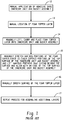
- a typical process flow 10 for placing and gluing a foam layer onto an innercore unit and foam encased bucket assembly includes one or more operators physically applying adhesive to the top surface of the innercore unit and bucket assembly. Generally, this requires a first step 12 of applying (e.g., spraying) the adhesive onto the top surface of the assembly. Once the adhesive is applied, the one or more operators locate the desired foam layer for placement as shown in step 13.
- step 15 The operators then lift and carry the foam layer, and place the foam layer onto the innercore unit and bucket assembly as provided in step 14. As shown in step 15, the operators then manually stretch certain portions of the foam layer so as to completely cover any underlying top surface of the innercore unit and bucket assembly. Likewise, portions of the foam layer that extend beyond the top surface of the innercore unit and bucket assembly are lifted and realigned with an edge of the top surface. The operators then smooth out the surface and may push down on the foam layer to insure sufficient contact with the applied adhesive as provided in step 16. If the mattress build specifications require additional foam layers, the operators then locate the particular foam layer and repeat the above described process as provided in step 17.
- the above process has inherent variability as these particular steps are operator driven and manually performed.
- Application of the adhesive itself can vary across the top surface of the innercore unit and bucket assembly since the amounts are not regulated leading to frequent instances of inadequate adhesive as well as excessive application.
- Inadequate glue as well as variability across the surface can lead to failures, which directly affect quality.
- Excessive adhesive application translates directly to increased costs.
- the time to perform the above described processes can be lengthy and can be a source of error when the wrong foam layer is located and placed. Still further, any pressure applied by the operator is highly variable.
- the process for accurately securing one or more foam layers onto an innercore unit and bucket assembly comprises automatically sizing the foam layer by compressing and stretching the foam layer to define a nominal size; automatically applying an adhesive to a top surface of an innercore unit and bucket assembly; automatically aligning the inner core unit and bucket assembly to a base corner datum; and automatically lifting and placing the foam layer onto the top surface of the innercore unit and bucket assembly using the base corner datum as a reference point.
- An automated system for placing and securing one or more foam layers onto an innercore unit and bucket assembly comprises an adhesive application station for receiving an innercore unit and bucket assembly, the adhesive application station comprising a movable surface to support the innercore unit and bucket assembly and a bridge spaced from and spanning the movable surface, the bridge comprising one or more adhesive applicators oriented to discharge a controlled amount of adhesive in a defined pattern onto the a surface of the innercore unit and bucket assembly; an innercore unit and bucket assembly alignment station comprising a movable surface and an adjustable frame assembly configured to align the innercore unit and bucket assembly to a known datum point on the movable surface; a foam pick and placement station comprising a sizing table configured to compress and stretch the one or more foam layers to a nominal size; a lifting assembly comprising a plurality of lifting units spaced about an adjustable frame assembly so as to provide lifting and release of the foam layer from the sizing table when in use, and a robotic arm coupled to the adjustable frame assembly and configured to move the
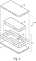
- FIG. 2 depicts an exemplary exploded perspective view of an innercore unit and bucket assembly with foam topper layers generally designated by reference numeral 20 employed in construction of the mattress.
- the bucket 22 generally includes a planar base layer 24 dimensioned to approximate the length and width dimensions of the intended mattress.
- the base layer 24 may consist of foam, fiber pad or it may comprise a wooden, cardboard, or plastic structure selected to provide support to the various components that define the mattress, e.g., innercore unit, side, end rails, and the like.
- stiffer or more compliant base layers may be chosen.
- the base layer 24 may be formed of a high density polyurethane foam layer (20-170 pounds-force, also referred to as the indention load deflection (ILD)), or several foam layers (20-170 pounds-force ILD each), that alone or in combination, provide a density and rigidity suitable for the intended mattress manufacture.
- foams or fiber pads may be used. Such a choice is well within the skill of an ordinary practitioner.
- An end and side rail assembly 26 which can be manufactured as a single piece or as multiple pieces, is affixed about the perimeter of the planar base layer 24 to define the bucket.
- the end and side rail assembly 26 is typically constructed from a dense natural and/or synthetic foam material of the type commonly used in the bedding arts.
- the foam may be (but is not limited to) latex, polyurethane, or other foam products commonly known and used in the bedding and seating arts and having a suitable density.
- a typical density is about, but not limited to 1.0 to 3.0 lb/ft 3 and more typically 1.5 to 1.9 lb/ft 3 , and a hardness of 35 to 70 ILD, and more typically 40 to 65.
- foam is the high density polyurethane foam and is commercially available from the Foamex Corporation in Linwood, Ill.
- any foam having a relatively high indention load deflection (ILD) would be satisfactory for the manufacture of the end and side rail assembly.
- ILD indention load deflection
- foam compositions other than one having this specific density and ILD can be used.
- foams of various types, densities, and ILDs may be desirable in order to provide a range of comfort parameters to the buyer.
- the size of the end and side rail assembly 26 can vary according to the mattress size and application, but each rail typically measures 3-10 inches (7.5-25 cm) in thickness.
- the depicted end and side rails are typically equal in width, and their length is chosen to correspond to the length of the size of mattress desired.
- the length of rails can be about 78.5 inches (200 cm), although the length can vary to accommodate the width of the header or footer, if the header or footer is to extend across the full width of the base platform 102.
- the header/footer piece typically has a thickness of about 3-10 inches (7.7-25 cm), and the width is chosen to correspond to the width of the size of mattress desired. In the case of a regular king size mattress the width would be about 75.25 inches (191 cm), and for a queen size mattress, the width would be about 59.25 inches (151 cm), depending on how the foam rails are arranged to form the perimeter sidewall.
- the end and side rail assembly 26 can be mounted or attached to base layer 24 by conventional means, such as (but not limited to) gluing, stapling, heat fusion or welding, or stitching.
- the bucket 22 formed of the base layer 24 and end and side rail assembly 26 as constructed defines a well or cavity 28.
- the well or cavity 28 provides a space in which the innercore unit 30 can be inserted.
- the innercore unit 30 may be comprised of conventional helical or semi-helical coil springs and/or foam known and used in the art today.
- the coil springs may be open or encased in a fabric material, either individually in pockets, in groups, or in strings joined by fabric, all of which are well-known in the bedding art.
- Marshall Construction one form of spring assembly construction has been known as Marshall Construction.
- Marshall Construction individual wire coils are each encapsulated in fabric pockets and attached together in strings which are arranged to form a closely packed array of coils in the general size of the mattress. Examples of such construction are disclosed in U.S. Pat. No. 685,160 , U.S. Pat. No. 4,234,983 , U.S. Pat. No.
- the innercore unit may be formed of foam or a combination of foam and coils springs.
- the foam in some embodiments, can be a monolithic block of a single type of resilient foam selected from foams having a range of densities (themselves well-known in the art) or multiple foam layers for supporting one or more occupants during sleep.
- foam within the innercore unit is made of any industry-standard natural and/or synthetic foams, such as (but not limited to) latex, polyurethane, or other foam products commonly known and used in the bedding and seating arts having a density of 1.5 to 1.9 lb/ft 3 and 20 to 35 pounds-force ILD.
- foam compositions other than one having this specific density and ILD can be used.
- foams of various types, densities, and ILDs may be desirable in order to provide a range of comfort parameters to the buyer.
- the foam innercore unit may comprise one or more horizontal layers of multiple types of foams arranged in a sandwich arrangement. This sandwich of different foams, laminated together, may be substituted for a homogeneous foam block of a single density and/or ILD.
- the foam core may comprise one or more vertical regions of different foam compositions (including vertical regions having multiple horizontal layers), where the different foams are arranged to provide different amounts of support (also referred to as "firmness” in the art) in different regions of the sleeping surface.
- the present disclosure is not limited to any particular type of foam density or ILD or even to a homogenous density/ILD throughout the foam core.
- the innercore unit may comprise one or more air bladders by themselves or in combination with coil springs, foam, or combinations thereof.
- the innercore unit and bucket assembly are then overlayed with one or more foam topper layers 32 on the top surfaces, and the whole assembly is encased within a ticking, often quilted, that is sewn closed around its periphery to a border or boxing. After assembly, the mattress can be covered by any other decorative covering or pillow-top.
- the apparatus and process are directed to precision placement and securement of the one or more foam top layers 32 to the top surface of the innercore unit and bucket assembly.
- the resulting mattress is not intended to be limited and may be of any type, dimension, and/or shape.
- the mattress may be a foam mattress, a coiled mattress, a foam and coil mattress, an air mattress, combinations thereof, or the like.
- the mattress is square or rectangular-shaped and has a thickness ranging from about 4 inches to about 20 inches.
- the length and width can vary depending on the intended application and typically has a width of about 2 feet to about 7 feet and a length of about 4 feet to about 10 feet, although custom sizes may require smaller or larger dimensions.
- the apparatus generally designated by reference numeral 50, includes an adhesive applicator station 100 for automatically applying controlled amounts of adhesive in a desired pattern onto a top surface of an innercore unit and bucket assembly (or in the case where one foam layer has already been placed and adhesively secured, onto the top surface of the foam layer); an innercore unit and bucket assembly alignment station 150 for automatically aligning and accurately defining a position thereof; automated delivery/transfer of a foam layer from an automated guide vehicle to the sizing table (not shown), a foam layer sizing and robotic transfer station 200 for automatically delivering, locating, sizing, picking, and placing one or more foam layers onto the innercore unit and bucket assembly; and a compression station 300 for compressing the foam layer(s) onto the innercore unit and bucket assembly to provide consistent adhesion of the foam layer to the underlying top surface of the innercore unit and bucket assembly.
- an adhesive applicator station 100 for automatically applying controlled amounts of adhesive in a desired pattern onto a top surface of an innercore unit and bucket assembly (or in the case where one foam layer has already been
- each station includes a movable surface (e.g., a conveyor rotatably driven by a motor) to define a travel path of the innercore unit and bucket assembly during alignment and as the foam layer(s) is placed thereon.
- a movable surface e.g., a conveyor rotatably driven by a motor
- the apparatus 50 is not intended to be limited to the particular configuration as shown. Other variations and configurations will be apparent to those skilled in the art in view of this disclosure.
- the movable surfaces of the stations, 100, 150, and 300 are generally coplanar to each other to permit transfer into and out of the respective stations as will be described in greater detail below.
- the tables supporting the various movable surfaces may also be interconnected to provide greater stability or may be fixedly attached to the ground.
- the foam layer sizing and robotic transfer station 200 is adjacent to the serially aligned adhesive applicator station 100, innercore unit and bucket assembly alignment station 150, and the compression station 300. In the embodiment as shown, the foam layer sizing and robotic transfer station 200 is immediately adjacent to the innercore unit and bucket assembly alignment station 150 to minimize the travel of the robot to effect placement of the foam layer from the sizing table onto the innercore unit and bucket assembly within the innercore unit and bucket assembly alignment station 150.
- the apparatus and process is operably linked to a programmable logic control system (PLC system) or serial bus system and/or manufacturing execution solution (MES system) to plan and schedule the different process steps as well as minimize and/or eliminate manual labor, which represents a significant departure from prior art assembly processes.
- PLC system programmable logic control system
- MES system manufacturing execution solution
- Each station is configured to communicate with the MES system, which are commercially available from a variety of suppliers, e.g., Preactor from Siemens AG. Designing the appropriate algorithms to perform the various steps to plan, schedule, operate, and control the system is well within the skill of those in the art.
- the data and inputs for operating the systems are generally available to an operator via a computer interactive display.
- Suitable actuators include servomotors, stepper motors, pneumatic actuators, hydraulic actuators, and the like.
- FIG. 4 there is shown a top down view of the adhesive applicator station 100, which includes a table 101 having a generally planar support surface 102 configured to support the innercore unit and bucket assembly during the process of applying adhesive to the innercore unit and bucket assembly.
- the support surface 102 can be elevated relative to ground and may include a movable support surface (i.e., a conveyor) for transferring the innercore unit and bucket assembly into and out of the station.
- the movable support surface is not intended to be limited to any particular type and may include a plurality of rollers and/or a rotatable belt rotatably driven by a motor for automatically moving the innercore unit and the bucket assembly into and/or out of the adhesive application station. Adjustment to the speed of the movable support surface allows for tailored feed rates to pair the adhesive application with placement of the foam layer or the like, thereby providing reproducible adhesive volume application in a desired pattern.
- the adhesive applicator station 100 further includes a bridge 106 carried by supports 108, wherein the bridge laterally spans across the length or width dimension of the support surface 102.
- the bridge may be mounted directly to the underlying support surface 102.
- the bridge 106 generally spans a width dimension of the support surface, which during operation extends beyond a width dimension of the innercore unit and bucket assembly.
- the bridge is elevated relative to the support surface and positioned proximate to the innercore unit and bucket assembly alignment station 150, wherein the bridge is at a height from the support surface effective to permit clearance of the innercore unit and bucket assembly, with or without additional foam layers disposed thereon.
- the bridge may be vertically movable, which is desired for the glue application to achieve consistent glue spray patterns.
- the bridge has coupled thereto one or more adhesive applicators 110, which may be statically or dynamically mounted to the bridge.
- the adhesive applicators are oriented to apply a desired pattern of adhesive to a top surface of an underlying innercore unit and bucket assembly (or foam layer if one is already placed and secured thereto). In this manner, adhesive may be applied to the top surface as the innercore unit and bucket assembly (or foam layer) as the assembly is conveyed into and from the adhesive applicator station.
- the adhesive applicator(s) is configured to provide a controlled amount of adhesive in a desired pattern to the top surfaces innercore unit and bucket assembly (or foam layer).
- the adhesive applicator(s) may be moveable across the bridge so that application of the adhesive can be optimally located for each size and/or type of innercore unit and bucket assembly and/or foam layer as well as providing a desired pattern of the adhesive.
- the application of the adhesive may be intermittent or continuous. Similarly, the adhesive may be applied to the entire top surface or to selected portions thereof as may be desired in some applications.
- the adhesive applicator includes a plurality of nozzles in fluid communication with a source of adhesive such as a hot melt adhesive.
- the adhesive applicator may be coupled to a motion detector system or sensor system (not shown) for actuating the nozzles as the innercore unit and bucket assembly is transferred into and/or out of the adhesive application station 100.
- Adhesive application can be triggered by the product presence sensors in conjunction with PLC logic code to ensure exact start and stop of adhesive application for the particular mattress size.
- the PLC/MES system may be programed to adjust the adhesive application based on the type of foam topper (density and ILD) and foam layer sequence (e.g., third foam layer on the inner core unit and bucket assembly which is close to the mattress surface assumes incremental movement and can require a different glue pattern compare to other stackedly arranged foam layers, e.g., additional foam layers and/or the first foam layer disposed on the innercore unit and bucket assembly).
- the adhesive applicator 110 is a dual pump spray system that provides a metered volume and the nozzles therein are configured to provide a desired pattern of an adhesive through the use of the programmable logic control device and/or glue spray pattern code/logic.
- actuation of the adhesive applicator can be configured to occur upon detection by the motion detector system of the leading edge of the innercore unit and bucket assembly traveling underneath the adhesive applicator and discontinued upon detection of the trailing edge of the bucket.
- the automation provided by the adhesive applicator(s) provides controlled adhesive application and patterning, thereby allowing for significantly more consistent and repeatable application of the adhesive as compared to prior art processes.
- significant cost savings can be realized relative to the prior art manual spray application of the adhesive by an operator.
- the innercore unit and bucket assembly alignment station 150 shown in FIGS. 6-7 includes a support surface 152 for supporting the innercore unit and bucket assembly during alignment as well as during foam layer placement.
- the support surface 152 may include a movable support surface for transferring the innercore unit and bucket assembly into and out of the station.
- the movable support surface is not intended to be limited to any particular type and may include a plurality of rollers and/or a rotatable belt rotatably driven by a motor for automatically moving the innercore unit and the bucket assembly into and/or out of the adhesive application station.
- the alignment station 150 further includes an adjustable rail assembly 160 for aligning the innercore unit and bucket assembly to a precise reproducible location.
- the rail assembly generally includes two reference rails 162, 164 that collectively define a base datum corner of the innercore unit and bucket assembly when seated against these rails.
- Reference rail 162 extends along a side of the support surface 152 (i.e., the x-direction and is generally parallel to the travel path of the innercore unit and bucket assembly) and reference rail 164 is transverse to the support surface 152 and is positioned at the edge of the support surface 152 (i.e., the y-direction and is generally perpendicular to the travel path of the innercore and bucket assembly).
- Reference rail 162 may be fixedly mounted to the side 167 of the support surface 152.
- Reference rail 164 is disposed at support surface end 169 generally perpendicular to the travel path of the innercore unit and bucket assembly. Both rails 162, 164 may be vertically retractable with respect to ground via an actuator controlled by the PLC system. During the alignment process, reference rail 164 is in the raised position as shown and during transfer from one station to another, the rail may be retracted so as to permit the innercore unit and bucket assembly to travel unimpeded along the travel path.
- the adjustable rail assembly further includes movable rails 166 and 168, wherein the rails 162, 164, 166, and 168, collectively frame the innercore unit and bucket assembly during the alignment process with movable rails 166 and 168 pushing the innercore unit and bucket assembly against the reference rails, thereby establishing a base datum reference indicative of the exact position and orientation of the innercore unit and bucket assembly.
- Movable rail 166 is positioned parallel to the travel path of the innercore unit and bucket assembly and is configured to move in the y-direction so as to compress against a sidewall of the innercore unit and bucket assembly when in use and movable rail 168 is configured to push against a sidewall of the innercore unit and bucket assembly in the x-direction.
- Each of the rails 162, 164, 166, and 168 includes a planar surface perpendicular to the support surface. In this manner, during alignment the movable rails 166, 168 serve to push the innercore unit and bucket assembly against reference rails 162, 164 such that a corner of the innercore unit and bucket assembly is seated against reference rails 162, 164 at a precise, reproducible location and orientation.
- Movable rail 166 is movably disposed on a support surface 170 that is adjacent and coplanar to end 171 of the support surface 152.
- Support surface 170 includes one or more track guides 174 that are generally perpendicular to the travel path of the innercore unit and bucket assembly.
- An arm 176 is attached at one end to a back side of the rail 166 and at the other end movably coupled to the track guide.
- the particular numbers of arms attached to the rail 166, three of which are shown, are not intended to be limited.
- At least one arm is operably linked to rail 166.
- the number of track guides is not intended to be limited and will generally correspond to the number of arms.
- An actuator controlled by the PLC system is operably linked to the arm to selectively move rail 166 along the track guide 174.
- Movable rail 168 is attached to a hinge 178 at one end 179 and to a retractable arm 180 at about the other end 182.
- the retractable arm 180 provides rotation about an axis of the hinge 178 such that when in use the rail 168 is positioned to be parallel to a sidewall of the innercore unit and bucket assembly and when not in use the rail is retracted away from the sidewall. As shown, retraction of the arm 180 in the direction shown by arrow 182 swings the rail 168 out of the travel path of the innercore unit and bucket assembly.
- the hinge 178 (and rail 168) is movably coupled to guide rails 176 to effect linear movement of the rail along the travel path if the innercore unit and bucket assembly.
- the movable rail may further include a stop (not shown) for receiving the rail when retracted.
- the stop may be magnetic and may include a recess for receiving the rail.
- One or more actuators e.g., servomotors, two of which are shown, are operably linked to the rail 168 to provide extension and retraction of rail as well as to movement of the rail along the guide rails.
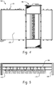
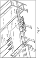
- the foam layer sizing and robotic transfer station 200 which generally includes a robotic lifting assembly 202 and a foam layer sizing table 204.
- the robotic lifting assembly 202 moves in response to command signals to lift a nominally sized foam layer from the sizing table 204 and precisely place the foam layer onto the innercore unit and bucket assembly.
- the robotic lifting assembly 202 generally includes a multi-axis functional robot 205 and a lifting assembly 206 attached to an arm 207 of the multi-axis functional robot.
- the robot itself is not intended to be limited and is commercially available from numerous sources.
- An exemplary industrial robot for picking and placing the foam layer is commercially available from ABB Ltd.
- the sizing table 204 includes a generally planar surface 250 for supporting the foam layer during the sizing process.
- the planar surface 250 may include a plurality of perforations 252 extending through the surface.
- the sizing table 204 further includes an adjustable rail assembly 254 shown more clearly in FIG. 10 for sizing the foam layer to a nominal size and providing a precise reproducible location to the apparatus.
- nominal size is to be accorded its usual and customary meaning. In general, nominal size refers to a standardized dimension specific to the intended mattress dimension, e.g., twin, queen and the like.
- the nominally sized foam layer will generally be sized to match the length and width dimensions of the innercore unit and bucket assembly (or foam layer disposed thereon) to which the nominally sized foam layer is to be attached.
- the adjustable rail assembly 254 is configured to frame the foam layer as shown in FIG. 9 and automatically compress the foam layer to less than nominal size followed by stretching of the foam layer to the nominal size defined by the programmed specification for the particular foam layer, which is then lifted and subsequently placed on the innercore unit and bucket assembly via the robotic lifting assembly 202.
- the adjustable rail assembly 254 provides a base datum corner 256 for the foam layer, which is then matched with the base datum corner of the aligned innercore unit and bucket assembly to provide precise placement and orientation of the foam layer onto the innercore unit and bucket assembly.
- the adjustable rail assembly 254 generally includes two reference rails 258, 260 adjustably positioned on the sizing table 204 that generally intersect at one end at a right angle on the table at a known location so as to collectively define the base datum corner 256 for the foam layer when seated against these rails.
- Reference rail generally 258 generally corresponds to a width dimension of the foam layer and reference rail 260 generally corresponds to a length dimension of the foam layer.
- the adjustable rail assembly further includes movable rails 262 and 264, wherein the rails 258, 260, 262, and 264 collectively frame the foam layer during the sizing process with the movable rails 262 and 264 aligning the foam layer, which is then compressed by the rails 258, 260, 262, and 264.
- the rails may be of unitary construction or may comprise segments of equal or differing lengths, wherein each segment may be independently controlled by an actuator, e.g., a pneumatic actuator.
- Movable rail 262 is positioned parallel to reference rail 258 and movable rail 264 is positioned parallel to reference rail 260 so as to define the adjustable rail assembly 254.
- Each of the rails 258, 260, 262, and 264 includes a planar surface perpendicular to surface 250. In this manner, during sizing the rails 258, 260, 262, 264 serve to compress the foam layer against the respective opposing rail.
- the surface 250 further includes one or more track guides 270 that are generally perpendicular to rails 258, 260, 262, and 264.
- the rails are operably coupled to the track guides 270 via an arm 272 attached at one end to a back side of the rails and at the other end movably coupled to the track guide.
- the particular numbers of arms attached to the rails are not intended to be limited. At least one arm is operably linked to the rail.
- the number of track guides is not intended to be limited and will generally correspond to the number of arms.
- An actuator such as a servomotor controlled by the PLC system is operably linked to the arms to selectively and precisely move the rails along the corresponding track guide 270.
- Movable rails 262 and 264 include longer track guides to accommodate different size foam layers whereas rails 258 and 260 include shorter track guides to provide compression of the foam layer during the sizing process.
- Each of the rails 258, 260, 262, and 264 further includes a gripper assembly for clamping onto the foam layer during the stretching step of the sizing process.
- the foam layer is first compressed against the rails to less than nominal size.
- the gripper assemblies disposed on the rails 258, 260, 262, 264 are actuated to clamp downward onto the foam layer and rails 262, 264 are then moved to a predefined position.
- the movement of rails 262, 264 to the predefined position stretches the foam layer to its nominal size as defined by the foam layer specification.
- the gripper assemblies 280 are generally pivotably coupled to and spaced about the rails to provide controlled gripping of the foam at the edge and stretching.
- the particular gripper assemblies 280 are not intended to be limited.
- An exemplary gripper assembly is shown in FIGS. 11-13 , wherein the gripper assembly 280 generally includes an actuator 282, e.g., a linear actuator or the like, that is coupled at one end to bar 284 and at the other end to a second actuator 285 disposed underneath the table 204 via a link 286 engaged within track guide 270.
- Actuation of the second actuator effects precision movement of the rail e.g., rail 258, across the surface 252 of the sizing table 204.
- the bar 284 is pivotably coupled to the rail and attached to a pivotably movable upper plate 288.
- the rail further includes a lower plate 290 upon which an outer periphery of the foam layer is generally disposed on after the foam layer is placed on the sizing table and compressed.
- Actuation of the actuator 284 pivotably lowers the movable upper plate 288 so as to sandwich the outer periphery of the foam layer between the movable upper plate 288 and the lower plate 290.
- Subsequent movement of the second actuator outwardly from the foam layer causes the rails to stretch the foam layer. Movement across the table is carefully controlled so that the foam layer is stretched to its nominal size.
- sensors may be located on the rails to assist in aligning the gripper assemblies to the edges of the foam layer.
- Servomotors may be employed to move the rails to the programmed position, e.g., moves the rails including the gripper assemblies to contact foam layer
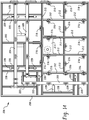
- the lifting assembly 206 includes a frame 208 with a primary beam 210 bisecting the frame 208 at about a midpoint. Secondary beams 212 are coupled to the beam 210 and/or the frame 206 to define a rectangularly shaped portion of the lifting assembly having attached thereto statically positioned lifting units 216 in a spaced arrangement about the rectangularly shaped portion, wherein the rectangularly shaped portion overlays a major portion of an underlying foam layer.
- the lifting assembly 206 further includes support beams 220 for supporting movable beams 222, 224, and 226 mounted thereto. Each movable beam 222, 224, and 226 includes additional lifting units 216 spacedly arranged on the beams.
- the position of the lifting units 216 may be adjustable on the rail.
- the position of these movable beams 222, 224, and 226 can be selected and optimized based on the dimensions of the foam layer to be lifted corresponding to the mattress size.
- movable beam 222 can be selectively moved to accommodate the manufacture of mattresses having various lengths e.g., standard, long, extra-long, etc.
- movable beams 224 and 226 can be selectively moved to accommodate the manufacture of mattresses having various widths, e.g., twin, full, queen, king, etc.
- the movable beams are generally positioned to overlay an edge of the underlying foam layer that is outside the area overlayed by the statically positioned rectangular shaped portion discussed above.
- the position of the movable beams can be programmed in the PLC system. Precise movement of the rails can be provided by precision ball bearing slides or the like.
- An attachment plate 214 is centrally located on the frame and provides the means for attaching the arm to the lifting assembly.
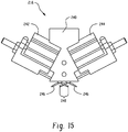
- each one of the lifting units 216 generally includes a head 240 that supports two slides 242, 244, each of which is provided with one or more retractable angled needles 246 (shown extended from the head).
- the needles on one slide face towards the needles of the other slide, sloping one towards the others.
- the needles are at an angle relative to a foam layer of about 30 (150) to about 60 (120) degrees in most embodiments, although angles greater or less than this range can be used. In one embodiment, the needles are at an angle of 45 (135) degrees.
- the needles from the respective slides are spaced by a gap 248 such that the needles from the opposing slides overlap when extended into the foam layer.
- Both of the slides, and with them the needles that are fixed to them, are controlled and movable in opposite directions between an idle position, in which the needles on one slide are retracted and are at a distance from those on the other slide, and an active position, in which the needles of the two slides move forward, cross each other and sloping penetrate into the element to be picked up and, with the help of a flat head, they are able to gather it and transfer it according to requirements.
- An exemplary needle gripper is commercially available from Schmalz Inc.
- Exemplary needle grippers are disclosed in U.S. Patent No. 8,104,807 and are commercially available from Schmalz, Inc.
- FIG. 16 depicts the lifting assembly 206 positioned to lift an exemplary underlying foam layer 500 that has previously been compressed and stretched to a nominal size.
- the movable beams 222 and 224 are optimally positioned such that lift units 216 are at positions disposed over a peripheral edge of the foam layer as well as spacedly and uniformly arranged over an interior region of the foam layer so as to lift the foam layer and maintain its nominal size.
- movable beam 226 is not needed to lift this particular sized foam layer and is positioned such that the lifting units disposed thereon do not overlay the foam layer.
- the sizing table 204 ( Fig 9 ) first receives a foam layer from a delivery system, e.g., manually placed by an operator or through an automated guide vehicle or robotic assist via grippers, or the like.
- the movable rail sections on the sizing table 204 are activated to match the size of the foam layer being sized.
- the actuators e.g., servomotors, are configured and programmed to move the rails until it contacts the foam layer.
- the adjustable rail assembly 254 holds the foam as it is transported to the base corner datum.
- the gripping assemblies 280 are then activated and the foam layer is stretched to its nominal size, which matches the length and width dimensions of the innercore unit and bucket assembly.
- the lifting assembly 206 is then robotically lowered onto the foam layer and the lifting units incorporating needles are activated to engage the foam layer.
- the foam layer at its nominal size is then placed onto the innercore unit and bucket assembly using the base corner datums as a reference point to provide precise placement of the foam layer.
- the sizing function may incorporate variable compression forces, variable stretching forces, and clamping based on the foam type with real time adjustments to achieve the intended functional value desired. Consequently, sizing of the foam layer will reduce process variability by providing consistency in terms of the size and precise placement of the foam layer onto the previously aligned and known position of the innercore unit and bucket assembly.
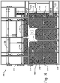
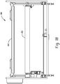
- the compression station 300 generally includes a support surface 302 coplanar and serially connected to the support surface of the alignment station 150.
- the support surface 302 may include a movable support surface for transferring the innercore unit and bucket assembly with the foam layer(s) thereon into and out of the station.
- the movable support surface is not intended to be limited to any particular type and may include a plurality of rollers and/or a rotatable belt rotatably driven by a motor for automatically moving the innercore unit and the bucket assembly into and/or out of the adhesive application station.
- the compression station 300 further includes a vertically movable platen 304 disposed above the support surface.
- the platen 304 may be driven by actuators (not shown), e.g., pneumatic actuators, hydraulic actuators, or the like that move the platen vertically upward and downward such that when the innercore unit and bucket assembly having the foam layers disposed therein are transferred to the compression station, the platen is lowered to compress the assembly.
- actuators e.g., pneumatic actuators, hydraulic actuators, or the like that move the platen vertically upward and downward such that when the innercore unit and bucket assembly having the foam layers disposed therein are transferred to the compression station, the platen is lowered to compress the assembly.
- the compression of the assembly provides a predetermined and programmed pressure on the assembly to provide consistent and uniform downward pressure across the surface of uppermost foam layer, which serves to maximize contact of the adhesive between the various layers, thereby minimizing the amount of adhesive used compared to the prior art as well as providing reproducibility with regard to adhesive strength.
- the platen 304 has a substantially planar surface that contacts the surface of the uppermost foam layer.
- the platen is generally dimensioned such that the substantially planar surface can be configured to provide a constant pressure across the entire surface of whatever size foam layer the platen contacts. As such, the platen is generally dimensioned to be larger than the largest size mattress being assembled.
- the substantially planar surface may be formed of a single piece construction or may be formed of plates. In some embodiments, the individual plates may be independently actuatable so as to exert differing pressures as may be desired in some applications.
- the apparatus can be fully automated via a programmable logic control and/or manufacturing execution solution system (i.e., the PLC/MES system) using a radio frequency identification tag (RFID) for component identification.
- RFID tags may be affixed to the innercore unit and bucket assembly and/or foam layers and/or storage areas corresponding to the particular component for wireless recognition by the PLC/MES system. In this manner, orders can be managed and scheduled from the PLC/MES system.
- each of the various steps for placing and securing the foam layers onto the innercore unit and bucket assembly can be fully automated via the programmable logic control/manufacturing execution solution system, thereby requiring no operator interaction.
- Use of RFID tags for component identification enhances changeovers and allows for simple correction for variation between different innercore and bucket assembly types as well as different foam layer types.
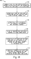
- the process 400 of operating the apparatus 50 generally includes a first step 402 of delivering a foam layer to the robotic foam layer sizing and robotic transfer station 200.
- This step is automatically performed. For example, an operator manually places the foam on the automated guide vehicle which can be programmed to automatically locate and transfer a desired foam layer to the sizing and transfer station.
- the foam layer is then sized in the sizing station, which first compresses and then stretches the foam layer to a nominal size as shown in step 404.
- an innercore and bucket assembly Prior to or simultaneously with the location and sizing of the foam layer, an innercore and bucket assembly is provided to the adhesive application station 100 as shown in step 406.
- the innercore unit and bucket assembly can be directly fed from an innercore unit and bucket assembly apparatus.
- An exemplary innercore unit and bucket assembly apparatus is disclosed in US Patent Application No. 14/481,419 entitled: Mattress Manufacturing Process and Apparatus to Michael DiMarco and filed on September 9, 2014.
- the innercore unit and bucket assembly can be transferred to the conveyor of the adhesive application station where a predetermined pattern and volume of adhesive is then applied to the top surface.
- the innercore unit and bucket assembly with the applied adhesive is then transferred to the alignment station 150 for alignment. All four sides are aligned as shown in step 408, wherein the coordinates are provided to the programmable logic control system.
- the foam layer at the nominal size is then picked up from the foam layer sizing and robotic transfer station 200 and placed on the top surface of the aligned inner core unit and bucket assembly as shown in step 410. In this manner, the foam layer is precisely placed on the top surface of the innercore unit and bucket assembly (or previously deposited foam layer) and onto a controlled amount and defined pattern of adhesive. The process is then repeated until all foam layers for the mattress design build are placed as provided in step 412.
- the assembly is transferred to the compression station, wherein downward pressure is applied onto the assembly to insure maximum and consistent adhesion of the foam layer to the innercore unit and bucket assembly.
- the programmable logic control system may be programmed to provide the step of compression after each foam layer is adhesively placed, after selected foam layers are placed, or after all of the layers are placed. The system provides latitude as to when this may occur.
Description
- The present disclosure generally relates to mattress manufacture, and more particularly, to an automated foam layer placement apparatus for accurately securing one or more foam layers onto an innercore unit and bucket assembly.
- Current processes for manufacturing the mattress include numerous steps utilizing manual labor including, among others, the process of adhesively securing one or more foam top layers, i.e., topper layers, onto a top surface provided by innercore unit and foam encased bucket assembly. For example, as shown in prior art
FIG. 1 , a typical process flow 10 for placing and gluing a foam layer onto an innercore unit and foam encased bucket assembly includes one or more operators physically applying adhesive to the top surface of the innercore unit and bucket assembly. Generally, this requires afirst step 12 of applying (e.g., spraying) the adhesive onto the top surface of the assembly. Once the adhesive is applied, the one or more operators locate the desired foam layer for placement as shown instep 13. The operators then lift and carry the foam layer, and place the foam layer onto the innercore unit and bucket assembly as provided instep 14. As shown instep 15, the operators then manually stretch certain portions of the foam layer so as to completely cover any underlying top surface of the innercore unit and bucket assembly. Likewise, portions of the foam layer that extend beyond the top surface of the innercore unit and bucket assembly are lifted and realigned with an edge of the top surface. The operators then smooth out the surface and may push down on the foam layer to insure sufficient contact with the applied adhesive as provided instep 16. If the mattress build specifications require additional foam layers, the operators then locate the particular foam layer and repeat the above described process as provided instep 17. - Not surprisingly, the above process has inherent variability as these particular steps are operator driven and manually performed. Application of the adhesive itself can vary across the top surface of the innercore unit and bucket assembly since the amounts are not regulated leading to frequent instances of inadequate adhesive as well as excessive application. Inadequate glue as well as variability across the surface can lead to failures, which directly affect quality. Excessive adhesive application, translates directly to increased costs. Moreover, the time to perform the above described processes can be lengthy and can be a source of error when the wrong foam layer is located and placed. Still further, any pressure applied by the operator is highly variable.
- Disclosed herein are processes and systems for manufacturing a mattress. The process for accurately securing one or more foam layers onto an innercore unit and bucket assembly comprises automatically sizing the foam layer by compressing and stretching the foam layer to define a nominal size; automatically applying an adhesive to a top surface of an innercore unit and bucket assembly; automatically aligning the inner core unit and bucket assembly to a base corner datum; and automatically lifting and placing the foam layer onto the top surface of the innercore unit and bucket assembly using the base corner datum as a reference point.
- An automated system for placing and securing one or more foam layers onto an innercore unit and bucket assembly is also disclosed, The system comprises an adhesive application station for receiving an innercore unit and bucket assembly, the adhesive application station comprising a movable surface to support the innercore unit and bucket assembly and a bridge spaced from and spanning the movable surface, the bridge comprising one or more adhesive applicators oriented to discharge a controlled amount of adhesive in a defined pattern onto the a surface of the innercore unit and bucket assembly; an innercore unit and bucket assembly alignment station comprising a movable surface and an adjustable frame assembly configured to align the innercore unit and bucket assembly to a known datum point on the movable surface; a foam pick and placement station comprising a sizing table configured to compress and stretch the one or more foam layers to a nominal size; a lifting assembly comprising a plurality of lifting units spaced about an adjustable frame assembly so as to provide lifting and release of the foam layer from the sizing table when in use, and a robotic arm coupled to the adjustable frame assembly and configured to move the adjustable frame assembly from the sizing table to the innercore unit and bucket assembly alignment station; and a compression station comprising a vertically adjustable platen spaced above a movable surface.
- The disclosure may be understood more readily by reference to the following detailed description of the various features of the disclosure and the examples included therein.
- Referring now to the figures wherein the like elements are numbered alike:
- Prior Art Figure (
FIG.) 1 depicts an exemplary process flow for manufacture of foam topper layers onto an innercore unit and bucket assembly; -
FIG. 2 illustrates an exploded perspective view of an exemplary assembled innercore unit and bucket assembly including a foam topper layer disposed thereon; -
FIG. 3 depicts a perspective view of an apparatus for accurately securing one or more foam topper layers onto an innercore unit and bucket assembly in accordance with an embodiment of the present disclosure; -
FIG. 4 depicts a perspective top down view of an adhesive applicator station utilized in the apparatus ofFIG. 3 ; -
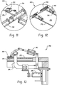
FIG. 5 depicts a side view of an exemplary glue bridge for the adhesive applicator station ofFIG. 4 ; -
FIG. 6 depicts partial perspective views of an innercore unit and bucket assembly alignment station utilized in the apparatus ofFIG. 3 ; -
FIG. 7 also depicts partial perspective views of an innercore unit and bucket assembly alignment station utilized in the apparatus ofFIG.3 ; -
FIG. 8 depicts a perspective view of a foam layer sizing and robotic transfer station utilized in the apparatus ofFIG. 3 ; -
FIG. 9 depicts a perspective view of an exemplary sizing table utilized in the foam layer sizing and robotic transfer station ofFIG. 8 ; -
FIG. 10 provides a top down view of the exemplary sizing table with positioning of the lifting units utilized in the foam layer sizing and robotic transfer station of FIG. - 8; -
FIG. 11 illustrates front and rear facing perspective views of a gripper assembly for use in compressing and stretching a foam layer in the foam layer sizing and robotic transfer station in accordance with an embodiment of the present disclosure; -
FIG. 12 also illustrates front and rear facing perspective views of a gripper assembly for use in compressing and stretching a foam layer in the foam layer sizing and robotic transfer station in accordance with an embodiment of the present disclosure -
FIG. 13 illustrates a sectional view of the gripper assembly ofFIGS. 11-12 ; -
FIG. 14 provides a top down view of the lifting assembly for use in the foam layer sizing and robotic transfer station in accordance with an embodiment of the present disclosure; -
FIG. 15 depicts an exemplary lifting unit for use in the lifting assembly in accordance with the present disclosure; and -
FIG. 16 depicts the lifting assembly positioned to lift a foam layer from the sizing table ofFIG. 9 ; -
FIG. 17 depicts a perspective view and an end on view, respectively, of a compression station utilized in the apparatus ofFIG. 3 ; -
FIG. 18 also depicts a perspective view and an end on view, respectively, of a compression station utilized in the apparatus ofFIG. 3 ; and -
FIG. 19 illustrates an exemplary process flow for assembling a foam topper layer(s) onto an innercore unit and bucket assembly in accordance with the present disclosure. - Disclosed herein are an apparatus and automated process for accurately placing and securing one or more foam layers onto an innercore unit and bucket assembly.
FIG. 2 depicts an exemplary exploded perspective view of an innercore unit and bucket assembly with foam topper layers generally designated byreference numeral 20 employed in construction of the mattress. Thebucket 22 generally includes aplanar base layer 24 dimensioned to approximate the length and width dimensions of the intended mattress. Thebase layer 24 may consist of foam, fiber pad or it may comprise a wooden, cardboard, or plastic structure selected to provide support to the various components that define the mattress, e.g., innercore unit, side, end rails, and the like. Depending on the innercore unit selected and its inherent stiffness, stiffer or more compliant base layers may be chosen. By way of example, thebase layer 24 may be formed of a high density polyurethane foam layer (20-170 pounds-force, also referred to as the indention load deflection (ILD)), or several foam layers (20-170 pounds-force ILD each), that alone or in combination, provide a density and rigidity suitable for the intended mattress manufacture. Other foams or fiber pads may be used. Such a choice is well within the skill of an ordinary practitioner. - An end and
side rail assembly 26, which can be manufactured as a single piece or as multiple pieces, is affixed about the perimeter of theplanar base layer 24 to define the bucket. The end andside rail assembly 26 is typically constructed from a dense natural and/or synthetic foam material of the type commonly used in the bedding arts. The foam may be (but is not limited to) latex, polyurethane, or other foam products commonly known and used in the bedding and seating arts and having a suitable density. A typical density is about, but not limited to 1.0 to 3.0 lb/ft3 and more typically 1.5 to 1.9 lb/ft3, and a hardness of 35 to 70 ILD, and more typically 40 to 65. One example of such a foam is the high density polyurethane foam and is commercially available from the Foamex Corporation in Linwood, Ill. Alternatively, any foam having a relatively high indention load deflection (ILD) would be satisfactory for the manufacture of the end and side rail assembly. Although a specific foam composition is described, those skilled in the art will realize that foam compositions other than one having this specific density and ILD can be used. For example, foams of various types, densities, and ILDs may be desirable in order to provide a range of comfort parameters to the buyer. - The size of the end and
side rail assembly 26 can vary according to the mattress size and application, but each rail typically measures 3-10 inches (7.5-25 cm) in thickness. The depicted end and side rails are typically equal in width, and their length is chosen to correspond to the length of the size of mattress desired. For a regular king size or queen size mattress, the length of rails can be about 78.5 inches (200 cm), although the length can vary to accommodate the width of the header or footer, if the header or footer is to extend across the full width of thebase platform 102. Similarly, the header/footer piece typically has a thickness of about 3-10 inches (7.7-25 cm), and the width is chosen to correspond to the width of the size of mattress desired. In the case of a regular king size mattress the width would be about 75.25 inches (191 cm), and for a queen size mattress, the width would be about 59.25 inches (151 cm), depending on how the foam rails are arranged to form the perimeter sidewall. - The end and
side rail assembly 26 can be mounted or attached tobase layer 24 by conventional means, such as (but not limited to) gluing, stapling, heat fusion or welding, or stitching. - The
bucket 22 formed of thebase layer 24 and end andside rail assembly 26 as constructed defines a well orcavity 28. The well orcavity 28 provides a space in which theinnercore unit 30 can be inserted. - As noted above, the
innercore unit 30 may be comprised of conventional helical or semi-helical coil springs and/or foam known and used in the art today. The coil springs may be open or encased in a fabric material, either individually in pockets, in groups, or in strings joined by fabric, all of which are well-known in the bedding art. For many years, one form of spring assembly construction has been known as Marshall Construction. In Marshall Construction, individual wire coils are each encapsulated in fabric pockets and attached together in strings which are arranged to form a closely packed array of coils in the general size of the mattress. Examples of such construction are disclosed inU.S. Pat. No. 685,160 ,U.S. Pat. No. 4,234,983 ,U.S. Pat. No. 4,234,984 ,U.S. Pat. No. 4,439,977 ,U.S. Pat. No. 4,451,946 ,U.S. Pat. No. 4,523,344 ,U.S. Pat. No. 4,578,834 ,U.S. Pat. No. 5,016,305 andU.S. Pat. No. 5,621,935 . - Alternatively, the innercore unit may be formed of foam or a combination of foam and coils springs. The foam, in some embodiments, can be a monolithic block of a single type of resilient foam selected from foams having a range of densities (themselves well-known in the art) or multiple foam layers for supporting one or more occupants during sleep. In one embodiment, foam within the innercore unit is made of any industry-standard natural and/or synthetic foams, such as (but not limited to) latex, polyurethane, or other foam products commonly known and used in the bedding and seating arts having a density of 1.5 to 1.9 lb/ft3 and 20 to 35 pounds-force ILD. Although a specific foam composition is described, those skilled in the art will realize that foam compositions other than one having this specific density and ILD can be used. For example, foams of various types, densities, and ILDs may be desirable in order to provide a range of comfort parameters to the buyer.
- In an alternative embodiment, the foam innercore unit may comprise one or more horizontal layers of multiple types of foams arranged in a sandwich arrangement. This sandwich of different foams, laminated together, may be substituted for a homogeneous foam block of a single density and/or ILD.
- In a further embodiment, the foam core may comprise one or more vertical regions of different foam compositions (including vertical regions having multiple horizontal layers), where the different foams are arranged to provide different amounts of support (also referred to as "firmness" in the art) in different regions of the sleeping surface.
- Accordingly, the present disclosure is not limited to any particular type of foam density or ILD or even to a homogenous density/ILD throughout the foam core.
- Still further, the innercore unit may comprise one or more air bladders by themselves or in combination with coil springs, foam, or combinations thereof.
- The innercore unit and bucket assembly are then overlayed with one or more foam topper layers 32 on the top surfaces, and the whole assembly is encased within a ticking, often quilted, that is sewn closed around its periphery to a border or boxing. After assembly, the mattress can be covered by any other decorative covering or pillow-top. In the present disclosure, the apparatus and process are directed to precision placement and securement of the one or more foam top layers 32 to the top surface of the innercore unit and bucket assembly.
- The resulting mattress is not intended to be limited and may be of any type, dimension, and/or shape. For example, the mattress may be a foam mattress, a coiled mattress, a foam and coil mattress, an air mattress, combinations thereof, or the like. Typically, the mattress is square or rectangular-shaped and has a thickness ranging from about 4 inches to about 20 inches. The length and width can vary depending on the intended application and typically has a width of about 2 feet to about 7 feet and a length of about 4 feet to about 10 feet, although custom sizes may require smaller or larger dimensions.
- Turning now to
FIG. 3 , the apparatus, generally designated byreference numeral 50, includes anadhesive applicator station 100 for automatically applying controlled amounts of adhesive in a desired pattern onto a top surface of an innercore unit and bucket assembly (or in the case where one foam layer has already been placed and adhesively secured, onto the top surface of the foam layer); an innercore unit and bucketassembly alignment station 150 for automatically aligning and accurately defining a position thereof; automated delivery/transfer of a foam layer from an automated guide vehicle to the sizing table (not shown), a foam layer sizing androbotic transfer station 200 for automatically delivering, locating, sizing, picking, and placing one or more foam layers onto the innercore unit and bucket assembly; and acompression station 300 for compressing the foam layer(s) onto the innercore unit and bucket assembly to provide consistent adhesion of the foam layer to the underlying top surface of the innercore unit and bucket assembly. - As shown, the
adhesive applicator station 100, innercore unit and bucketassembly alignment station 150, and thecompression station 300 are serially aligned with one another as shown, wherein each station includes a movable surface (e.g., a conveyor rotatably driven by a motor) to define a travel path of the innercore unit and bucket assembly during alignment and as the foam layer(s) is placed thereon. However, it should be apparent that theapparatus 50 is not intended to be limited to the particular configuration as shown. Other variations and configurations will be apparent to those skilled in the art in view of this disclosure. - The movable surfaces of the stations, 100, 150, and 300 are generally coplanar to each other to permit transfer into and out of the respective stations as will be described in greater detail below. The tables supporting the various movable surfaces may also be interconnected to provide greater stability or may be fixedly attached to the ground. The foam layer sizing and
robotic transfer station 200 is adjacent to the serially alignedadhesive applicator station 100, innercore unit and bucketassembly alignment station 150, and thecompression station 300. In the embodiment as shown, the foam layer sizing androbotic transfer station 200 is immediately adjacent to the innercore unit and bucketassembly alignment station 150 to minimize the travel of the robot to effect placement of the foam layer from the sizing table onto the innercore unit and bucket assembly within the innercore unit and bucketassembly alignment station 150. - The apparatus and process is operably linked to a programmable logic control system (PLC system) or serial bus system and/or manufacturing execution solution (MES system) to plan and schedule the different process steps as well as minimize and/or eliminate manual labor, which represents a significant departure from prior art assembly processes. Each station is configured to communicate with the MES system, which are commercially available from a variety of suppliers, e.g., Preactor from Siemens AG. Designing the appropriate algorithms to perform the various steps to plan, schedule, operate, and control the system is well within the skill of those in the art. The data and inputs for operating the systems are generally available to an operator via a computer interactive display. The various actuators controlled by the system employed to automate the process are not intended to be limited to any particular type, e.g., pneumatic, hydraulic, electrical, and the like. Suitable actuators include servomotors, stepper motors, pneumatic actuators, hydraulic actuators, and the like.
- Referring now to
FIG. 4 , there is shown a top down view of theadhesive applicator station 100, which includes a table 101 having a generallyplanar support surface 102 configured to support the innercore unit and bucket assembly during the process of applying adhesive to the innercore unit and bucket assembly. Thesupport surface 102 can be elevated relative to ground and may include a movable support surface (i.e., a conveyor) for transferring the innercore unit and bucket assembly into and out of the station. The movable support surface is not intended to be limited to any particular type and may include a plurality of rollers and/or a rotatable belt rotatably driven by a motor for automatically moving the innercore unit and the bucket assembly into and/or out of the adhesive application station. Adjustment to the speed of the movable support surface allows for tailored feed rates to pair the adhesive application with placement of the foam layer or the like, thereby providing reproducible adhesive volume application in a desired pattern. - As shown more clearly in
FIG. 5 , theadhesive applicator station 100 further includes abridge 106 carried bysupports 108, wherein the bridge laterally spans across the length or width dimension of thesupport surface 102. Optionally, the bridge may be mounted directly to theunderlying support surface 102. As shown, thebridge 106 generally spans a width dimension of the support surface, which during operation extends beyond a width dimension of the innercore unit and bucket assembly. The bridge is elevated relative to the support surface and positioned proximate to the innercore unit and bucketassembly alignment station 150, wherein the bridge is at a height from the support surface effective to permit clearance of the innercore unit and bucket assembly, with or without additional foam layers disposed thereon. In some embodiments, the bridge may be vertically movable, which is desired for the glue application to achieve consistent glue spray patterns. The bridge has coupled thereto one or moreadhesive applicators 110, which may be statically or dynamically mounted to the bridge. The adhesive applicators are oriented to apply a desired pattern of adhesive to a top surface of an underlying innercore unit and bucket assembly (or foam layer if one is already placed and secured thereto). In this manner, adhesive may be applied to the top surface as the innercore unit and bucket assembly (or foam layer) as the assembly is conveyed into and from the adhesive applicator station. - The adhesive applicator(s) is configured to provide a controlled amount of adhesive in a desired pattern to the top surfaces innercore unit and bucket assembly (or foam layer). In some embodiments, the adhesive applicator(s) may be moveable across the bridge so that application of the adhesive can be optimally located for each size and/or type of innercore unit and bucket assembly and/or foam layer as well as providing a desired pattern of the adhesive.
- In the foregoing embodiments, the application of the adhesive may be intermittent or continuous. Similarly, the adhesive may be applied to the entire top surface or to selected portions thereof as may be desired in some applications. In one embodiment, the adhesive applicator includes a plurality of nozzles in fluid communication with a source of adhesive such as a hot melt adhesive. The adhesive applicator may be coupled to a motion detector system or sensor system (not shown) for actuating the nozzles as the innercore unit and bucket assembly is transferred into and/or out of the
adhesive application station 100. Adhesive application can be triggered by the product presence sensors in conjunction with PLC logic code to ensure exact start and stop of adhesive application for the particular mattress size. The PLC/MES system may be programed to adjust the adhesive application based on the type of foam topper (density and ILD) and foam layer sequence (e.g., third foam layer on the inner core unit and bucket assembly which is close to the mattress surface assumes incremental movement and can require a different glue pattern compare to other stackedly arranged foam layers, e.g., additional foam layers and/or the first foam layer disposed on the innercore unit and bucket assembly).. In one embodiment, theadhesive applicator 110 is a dual pump spray system that provides a metered volume and the nozzles therein are configured to provide a desired pattern of an adhesive through the use of the programmable logic control device and/or glue spray pattern code/logic. For example, actuation of the adhesive applicator can be configured to occur upon detection by the motion detector system of the leading edge of the innercore unit and bucket assembly traveling underneath the adhesive applicator and discontinued upon detection of the trailing edge of the bucket. The automation provided by the adhesive applicator(s) provides controlled adhesive application and patterning, thereby allowing for significantly more consistent and repeatable application of the adhesive as compared to prior art processes. Moreover, by providing a specific pattern and volume of adhesive, significant cost savings can be realized relative to the prior art manual spray application of the adhesive by an operator. - The innercore unit and bucket
assembly alignment station 150 shown inFIGS. 6-7 includes asupport surface 152 for supporting the innercore unit and bucket assembly during alignment as well as during foam layer placement. Thesupport surface 152 may include a movable support surface for transferring the innercore unit and bucket assembly into and out of the station. The movable support surface is not intended to be limited to any particular type and may include a plurality of rollers and/or a rotatable belt rotatably driven by a motor for automatically moving the innercore unit and the bucket assembly into and/or out of the adhesive application station. - The
alignment station 150 further includes anadjustable rail assembly 160 for aligning the innercore unit and bucket assembly to a precise reproducible location. The rail assembly generally includes tworeference rails Reference rail 162 extends along a side of the support surface 152 (i.e., the x-direction and is generally parallel to the travel path of the innercore unit and bucket assembly) andreference rail 164 is transverse to thesupport surface 152 and is positioned at the edge of the support surface 152 (i.e., the y-direction and is generally perpendicular to the travel path of the innercore and bucket assembly).Reference rail 162 may be fixedly mounted to theside 167 of thesupport surface 152.Reference rail 164 is disposed atsupport surface end 169 generally perpendicular to the travel path of the innercore unit and bucket assembly. Bothrails reference rail 164 is in the raised position as shown and during transfer from one station to another, the rail may be retracted so as to permit the innercore unit and bucket assembly to travel unimpeded along the travel path. - The adjustable rail assembly further includes
movable rails rails movable rails Movable rail 166 is positioned parallel to the travel path of the innercore unit and bucket assembly and is configured to move in the y-direction so as to compress against a sidewall of the innercore unit and bucket assembly when in use andmovable rail 168 is configured to push against a sidewall of the innercore unit and bucket assembly in the x-direction. Each of therails movable rails reference rails reference rails -
Movable rail 166 is movably disposed on asupport surface 170 that is adjacent and coplanar to end 171 of thesupport surface 152.Support surface 170 includes one or more track guides 174 that are generally perpendicular to the travel path of the innercore unit and bucket assembly. Anarm 176 is attached at one end to a back side of therail 166 and at the other end movably coupled to the track guide. The particular numbers of arms attached to therail 166, three of which are shown, are not intended to be limited. At least one arm is operably linked torail 166. Likewise, the number of track guides is not intended to be limited and will generally correspond to the number of arms. An actuator controlled by the PLC system is operably linked to the arm to selectively moverail 166 along thetrack guide 174. -
Movable rail 168 is attached to ahinge 178 at oneend 179 and to aretractable arm 180 at about theother end 182. Theretractable arm 180 provides rotation about an axis of thehinge 178 such that when in use therail 168 is positioned to be parallel to a sidewall of the innercore unit and bucket assembly and when not in use the rail is retracted away from the sidewall. As shown, retraction of thearm 180 in the direction shown byarrow 182 swings therail 168 out of the travel path of the innercore unit and bucket assembly. The hinge 178 (and rail 168) is movably coupled to guiderails 176 to effect linear movement of the rail along the travel path if the innercore unit and bucket assembly. When the arm is extended, travel of the rail168 along theguide rails 176 permits therail 168 to push against a sidewall of the innercore unit and bucket assembly. Optionally, the movable rail may further include a stop (not shown) for receiving the rail when retracted. The stop may be magnetic and may include a recess for receiving the rail. One or more actuators, e.g., servomotors, two of which are shown, are operably linked to therail 168 to provide extension and retraction of rail as well as to movement of the rail along the guide rails. - Turning now to
FIG. 8 , there is shown the foam layer sizing androbotic transfer station 200, which generally includes arobotic lifting assembly 202 and a foam layer sizing table 204. Therobotic lifting assembly 202 moves in response to command signals to lift a nominally sized foam layer from the sizing table 204 and precisely place the foam layer onto the innercore unit and bucket assembly. Therobotic lifting assembly 202 generally includes a multi-axisfunctional robot 205 and a liftingassembly 206 attached to anarm 207 of the multi-axis functional robot. The robot itself is not intended to be limited and is commercially available from numerous sources. An exemplary industrial robot for picking and placing the foam layer is commercially available from ABB Ltd. - As shown in
FIGS. 9-10 , the sizing table 204 includes a generallyplanar surface 250 for supporting the foam layer during the sizing process. Theplanar surface 250 may include a plurality ofperforations 252 extending through the surface. The sizing table 204 further includes anadjustable rail assembly 254 shown more clearly inFIG. 10 for sizing the foam layer to a nominal size and providing a precise reproducible location to the apparatus. As used herein, the term nominal size is to be accorded its usual and customary meaning. In general, nominal size refers to a standardized dimension specific to the intended mattress dimension, e.g., twin, queen and the like. The nominally sized foam layer will generally be sized to match the length and width dimensions of the innercore unit and bucket assembly (or foam layer disposed thereon) to which the nominally sized foam layer is to be attached. Theadjustable rail assembly 254 is configured to frame the foam layer as shown inFIG. 9 and automatically compress the foam layer to less than nominal size followed by stretching of the foam layer to the nominal size defined by the programmed specification for the particular foam layer, which is then lifted and subsequently placed on the innercore unit and bucket assembly via therobotic lifting assembly 202. As will be discussed in greater detail below, theadjustable rail assembly 254 provides abase datum corner 256 for the foam layer, which is then matched with the base datum corner of the aligned innercore unit and bucket assembly to provide precise placement and orientation of the foam layer onto the innercore unit and bucket assembly. - The
adjustable rail assembly 254 generally includes tworeference rails base datum corner 256 for the foam layer when seated against these rails. Reference rail generally 258 generally corresponds to a width dimension of the foam layer andreference rail 260 generally corresponds to a length dimension of the foam layer. - The adjustable rail assembly further includes
movable rails rails movable rails rails -
Movable rail 262 is positioned parallel toreference rail 258 andmovable rail 264 is positioned parallel toreference rail 260 so as to define theadjustable rail assembly 254. Each of therails surface 250. In this manner, during sizing therails - The
surface 250 further includes one or more track guides 270 that are generally perpendicular torails arm 272 attached at one end to a back side of the rails and at the other end movably coupled to the track guide. The particular numbers of arms attached to the rails are not intended to be limited. At least one arm is operably linked to the rail. Likewise, the number of track guides is not intended to be limited and will generally correspond to the number of arms. An actuator such as a servomotor controlled by the PLC system is operably linked to the arms to selectively and precisely move the rails along thecorresponding track guide 270.Movable rails rails - Each of the
rails rails rails gripper assemblies 280 are generally pivotably coupled to and spaced about the rails to provide controlled gripping of the foam at the edge and stretching. - The
particular gripper assemblies 280 are not intended to be limited. An exemplary gripper assembly is shown inFIGS. 11-13 , wherein thegripper assembly 280 generally includes anactuator 282, e.g., a linear actuator or the like, that is coupled at one end to bar 284 and at the other end to asecond actuator 285 disposed underneath the table 204 via alink 286 engaged withintrack guide 270. Actuation of the second actuator effects precision movement of the rail e.g.,rail 258, across thesurface 252 of the sizing table 204. Thebar 284 is pivotably coupled to the rail and attached to a pivotably movableupper plate 288. The rail further includes alower plate 290 upon which an outer periphery of the foam layer is generally disposed on after the foam layer is placed on the sizing table and compressed. Actuation of theactuator 284 pivotably lowers the movableupper plate 288 so as to sandwich the outer periphery of the foam layer between the movableupper plate 288 and thelower plate 290. Subsequent movement of the second actuator outwardly from the foam layer causes the rails to stretch the foam layer. Movement across the table is carefully controlled so that the foam layer is stretched to its nominal size. - In one embodiment, sensors may be located on the rails to assist in aligning the gripper assemblies to the edges of the foam layer. Servomotors may be employed to move the rails to the programmed position, e.g., moves the rails including the gripper assemblies to contact foam layer
- As shown more clearly in
FIG. 14 , the liftingassembly 206 includes aframe 208 with aprimary beam 210 bisecting theframe 208 at about a midpoint.Secondary beams 212 are coupled to thebeam 210 and/or theframe 206 to define a rectangularly shaped portion of the lifting assembly having attached thereto statically positioned liftingunits 216 in a spaced arrangement about the rectangularly shaped portion, wherein the rectangularly shaped portion overlays a major portion of an underlying foam layer. The liftingassembly 206 further includes support beams 220 for supportingmovable beams movable beam additional lifting units 216 spacedly arranged on the beams. In some embodiments, the position of the liftingunits 216 may be adjustable on the rail. The position of thesemovable beams movable beam 222 can be selectively moved to accommodate the manufacture of mattresses having various lengths e.g., standard, long, extra-long, etc. whereasmovable beams attachment plate 214 is centrally located on the frame and provides the means for attaching the arm to the lifting assembly. - As shown more clearly in
FIG. 15 , each one of the liftingunits 216 generally includes ahead 240 that supports twoslides gap 248 such that the needles from the opposing slides overlap when extended into the foam layer. - Both of the slides, and with them the needles that are fixed to them, are controlled and movable in opposite directions between an idle position, in which the needles on one slide are retracted and are at a distance from those on the other slide, and an active position, in which the needles of the two slides move forward, cross each other and sloping penetrate into the element to be picked up and, with the help of a flat head, they are able to gather it and transfer it according to requirements. An exemplary needle gripper is commercially available from Schmalz Inc. Exemplary needle grippers are disclosed in
U.S. Patent No. 8,104,807 and are commercially available from Schmalz, Inc. -
FIG. 16 depicts the liftingassembly 206 positioned to lift an exemplaryunderlying foam layer 500 that has previously been compressed and stretched to a nominal size. Themovable beams lift units 216 are at positions disposed over a peripheral edge of the foam layer as well as spacedly and uniformly arranged over an interior region of the foam layer so as to lift the foam layer and maintain its nominal size. In the embodiment shown,movable beam 226 is not needed to lift this particular sized foam layer and is positioned such that the lifting units disposed thereon do not overlay the foam layer. - During operation, the sizing table 204 (
Fig 9 ) first receives a foam layer from a delivery system, e.g., manually placed by an operator or through an automated guide vehicle or robotic assist via grippers, or the like. The movable rail sections on the sizing table 204 are activated to match the size of the foam layer being sized. The actuators, e.g., servomotors, are configured and programmed to move the rails until it contacts the foam layer. Theadjustable rail assembly 254 holds the foam as it is transported to the base corner datum. Thegripping assemblies 280 are then activated and the foam layer is stretched to its nominal size, which matches the length and width dimensions of the innercore unit and bucket assembly. The liftingassembly 206 is then robotically lowered onto the foam layer and the lifting units incorporating needles are activated to engage the foam layer. The foam layer at its nominal size is then placed onto the innercore unit and bucket assembly using the base corner datums as a reference point to provide precise placement of the foam layer. - Advantageously, the sizing function may incorporate variable compression forces, variable stretching forces, and clamping based on the foam type with real time adjustments to achieve the intended functional value desired. Consequently, sizing of the foam layer will reduce process variability by providing consistency in terms of the size and precise placement of the foam layer onto the previously aligned and known position of the innercore unit and bucket assembly.
- As shown in
FIGS. 17-18 , thecompression station 300 generally includes asupport surface 302 coplanar and serially connected to the support surface of thealignment station 150. Thesupport surface 302 may include a movable support surface for transferring the innercore unit and bucket assembly with the foam layer(s) thereon into and out of the station. The movable support surface is not intended to be limited to any particular type and may include a plurality of rollers and/or a rotatable belt rotatably driven by a motor for automatically moving the innercore unit and the bucket assembly into and/or out of the adhesive application station. - The
compression station 300 further includes a verticallymovable platen 304 disposed above the support surface. Theplaten 304 may be driven by actuators (not shown), e.g., pneumatic actuators, hydraulic actuators, or the like that move the platen vertically upward and downward such that when the innercore unit and bucket assembly having the foam layers disposed therein are transferred to the compression station, the platen is lowered to compress the assembly. The compression of the assembly provides a predetermined and programmed pressure on the assembly to provide consistent and uniform downward pressure across the surface of uppermost foam layer, which serves to maximize contact of the adhesive between the various layers, thereby minimizing the amount of adhesive used compared to the prior art as well as providing reproducibility with regard to adhesive strength. - The
platen 304 has a substantially planar surface that contacts the surface of the uppermost foam layer. The platen is generally dimensioned such that the substantially planar surface can be configured to provide a constant pressure across the entire surface of whatever size foam layer the platen contacts. As such, the platen is generally dimensioned to be larger than the largest size mattress being assembled. The substantially planar surface may be formed of a single piece construction or may be formed of plates. In some embodiments, the individual plates may be independently actuatable so as to exert differing pressures as may be desired in some applications. - As noted above, the apparatus can be fully automated via a programmable logic control and/or manufacturing execution solution system (i.e., the PLC/MES system) using a radio frequency identification tag (RFID) for component identification. By way of example, RFID tags may be affixed to the innercore unit and bucket assembly and/or foam layers and/or storage areas corresponding to the particular component for wireless recognition by the PLC/MES system. In this manner, orders can be managed and scheduled from the PLC/MES system. Still further, each of the various steps for placing and securing the foam layers onto the innercore unit and bucket assembly can be fully automated via the programmable logic control/manufacturing execution solution system, thereby requiring no operator interaction. Use of RFID tags for component identification enhances changeovers and allows for simple correction for variation between different innercore and bucket assembly types as well as different foam layer types.
- Turning now to
FIG. 19 , theprocess 400 of operating theapparatus 50 generally includes afirst step 402 of delivering a foam layer to the robotic foam layer sizing androbotic transfer station 200. This step is automatically performed. For example, an operator manually places the foam on the automated guide vehicle which can be programmed to automatically locate and transfer a desired foam layer to the sizing and transfer station. The foam layer is then sized in the sizing station, which first compresses and then stretches the foam layer to a nominal size as shown instep 404. - Prior to or simultaneously with the location and sizing of the foam layer, an innercore and bucket assembly is provided to the
adhesive application station 100 as shown instep 406. In one embodiment, the innercore unit and bucket assembly can be directly fed from an innercore unit and bucket assembly apparatus. An exemplary innercore unit and bucket assembly apparatus is disclosed inUS Patent Application No. 14/481,419 alignment station 150 for alignment. All four sides are aligned as shown instep 408, wherein the coordinates are provided to the programmable logic control system. - The foam layer at the nominal size is then picked up from the foam layer sizing and
robotic transfer station 200 and placed on the top surface of the aligned inner core unit and bucket assembly as shown instep 410. In this manner, the foam layer is precisely placed on the top surface of the innercore unit and bucket assembly (or previously deposited foam layer) and onto a controlled amount and defined pattern of adhesive. The process is then repeated until all foam layers for the mattress design build are placed as provided instep 412. - Subsequent to foam placement on the innercore and bucket assembly (or previously deposited foam layer), the assembly is transferred to the compression station, wherein downward pressure is applied onto the assembly to insure maximum and consistent adhesion of the foam layer to the innercore unit and bucket assembly. In situations where multiple foam layers are placed, the programmable logic control system may be programmed to provide the step of compression after each foam layer is adhesively placed, after selected foam layers are placed, or after all of the layers are placed. The system provides latitude as to when this may occur.
- This written description uses examples to disclose the invention, including the best mode, and also to enable any person skilled in the art to make and use the invention. The patentable scope of the invention is defined by the claims, and may include other examples that occur to those skilled in the art. Such other examples are intended to be within the scope of the claims if they have structural elements that do not differ from the literal language of the claims, or if they include equivalent structural elements with insubstantial differences from the literal languages of the claims.
Claims (19)
- A process for accurately securing one or more foam layers onto an innercore unit and bucket assembly, the process comprising:automatically sizing the foam layer by compressing and stretching the foam layer to define a nominal size;automatically applying an adhesive to a top surface of an innercore unit and bucket assembly;automatically aligning the inner core unit and bucket assembly to a base corner datum; andautomatically lifting and placing the nominally sized foam layer onto the top surface of the innercore unit and bucket assembly using the base corner datum as a reference point.
- The process of claim 1, further comprising compressing the foam layer onto the innercore unit and bucket assembly.
- The process of claim 1, wherein the innercore unit comprises spring coils, foam, and combinations thereof.
- The process of claim 1, wherein automatically applying an adhesive to a top surface of the innercore unit and bucket assembly comprises detecting a leading edge of the innercore unit and bucket assembly and applying a controlled amount of the adhesive in a particular pattern onto the top surface and discontinuing the adhesive upon detection of a trailing edge of the innercore unit and bucket assembly.
- The process of claim 1, wherein automatically aligning the inner core unit and bucket assembly to a base corner datum comprises pushing the inner core unit and bucket assembly into a corner defined by reference rails at right angles to each other.
- The process of claim 1, wherein automatically lifting and placing the foam layer onto the top surface of the innercore unit and bucket assembly using the base corner datum as a reference point comprises attaching the foam layer to a lifting assembly via a needle gripper, wherein the needle gripper comprises retractable angled needles configured to engage the foam layer when extended.
- The process of claim 1, wherein compressing and stretching of the foam layer comprises disposing an adjustable rail assembly about the foam layer configured to compress and stretch the foam layer to a nominal size.
- The process of claim 7, wherein the adjustable rail assembly comprises:a pair of longitudinal rails and a pair of transverse rails to frame a periphery of the foam layer, each rail having a contact surface perpendicular to the planar surface to provide compression of the foam layer when in use; andone or more adjustable clamps disposed on each rail having a fixed portion carried by the rail and configured to slide underneath the foam layer upon compression and an adjustable portion configured to clamp down on the foam layer to permit stretching of the foam layer to a nominal size when in use.
- The process of claim 8, wherein compressing the foam layer comprises simultaneously moving a selected one or both of the longitudinal rails towards each other and moving a selected one or both of the transverse rails towards each other.
- The process of claim 8, wherein stretching the foam layer comprises gripping an edge of the foam layer with each one of the longitudinal and transverse rails; and simultaneously moving a selected one or both of the longitudinal rails away from each other and moving a selected one or both of the transverse rails away from each other.
- An automated system for placing and securing one or more foam layers onto an innercore unit and bucket assembly, the system comprising:an adhesive application station (100) for receiving an innercore unit and bucket assembly, the adhesive application station comprising a movable surface to support the innercore unit and bucket assembly and a bridge (106) spaced from and spanning the movable surface, the bridge (106) comprising one or more adhesive applicators (110) oriented to discharge a controlled amount of adhesive in a defined pattern onto the a surface of the innercore unit and bucket assembly;an innercore unit and bucket assembly alignment station (150) comprising a movable surface and an adjustable frame assembly configured to align the innercore unit and bucket assembly to a known datum point on the movable surface;a foam pick and placement station comprising a sizing table configured to compress and stretch the one or more foam layers to a nominal size;a lifting assembly (206) comprising a plurality of lifting units (216) spaced about an adjustable frame assembly so as to provide lifting and release of the foam layer from the sizing table (204) when in use, and a robotic arm coupled to the adjustable frame assembly and configured to move the adjustable frame assembly from the sizing table (204) to the innercore unit and bucket assembly alignment station (150); anda compression station (300) comprising a vertically adjustable platen (304) spaced above a movable surface.
- The automated system of claim 11, wherein the movable surfaces of the adhesive application station, the innercore unit and bucket assembly alignment station, and the compression station are serially aligned and coplanar to one another to receive and discharge the innercore unit and bucket assembly during processing, and wherein the foam pick and placement station is immediately adjacent to the innercore unit and bucket assembly alignment station.
- The automated system of claim 11, further comprising a manufacturing execution system and programmable logic control for planning, scheduling, and controlling the adhesive application station, the innercore unit and bucket assembly alignment station, the lifting assembly, and the compression station.
- The automated system of claim 11, wherein each one of the plurality of lifting units comprises a housing supporting two slides, each slide provided with one or more of the retractable angled needles, wherein the one or more retractable angled needles on one slide face toward the one or more retractable angled needles of the other slide.
- The automated system of claim 14, wherein the angle of the one or more retractable needles in one slide is in a range of about 30 degrees to about 60 degrees relative to the plane of the foam layer and the angle of the one or more retractable needles in the other slide is in a range of about 120 to about 150 degrees relative to the plane of the foam layer such that the one or more retractable needles in the one slide and the other slide converge upon extension from the respective sliding.
- The automated system of claim 14, wherein the angle of the one or more retractable needles in one slide is about 45 degrees relative to the plane of the foam layer and the angle of the one or more retractable needles in the other slide is about 135 degrees relative to the plane of the foam layer such that the one or more retractable needles in the one slide and the other slide converge upon extension from the respective sliding.
- The automated system of claim 11, wherein the adhesive application station further comprises a motion sensor for detecting a leading and trailing edge of the innercore unit and bucket assembly.
- The automated system of claim 11, wherein the sizing table comprises an adjustable rail assembly comprising a pair of longitudinal rails and a pair of transverse rails to frame a periphery of the foam layer, each rail having a contact surface perpendicular to the planar surface to provide compression of the foam layer when in use; and one or more adjustable clamps disposed on each rail having a fixed portion carried by the rail and configured to slide underneath the foam layer upon compression and an adjustable portion configured to clamp down on the foam layer to permit stretching of the foam layer to a nominal size when in use.
- The automated system of claim 11, wherein the sizing table further comprises a plurality of perforations in fluid communication with a vacuum.
Applications Claiming Priority (2)
| Application Number | Priority Date | Filing Date | Title |
|---|---|---|---|
| US201562106938P | 2015-01-23 | 2015-01-23 | |
| PCT/US2016/014473 WO2016118829A1 (en) | 2015-01-23 | 2016-01-22 | Mattress manufacturing process and apparatus |
Publications (2)
| Publication Number | Publication Date |
|---|---|
| EP3247671A1 EP3247671A1 (en) | 2017-11-29 |
| EP3247671B1 true EP3247671B1 (en) | 2018-12-19 |
Family
ID=55346206
Family Applications (1)
| Application Number | Title | Priority Date | Filing Date |
|---|---|---|---|
| EP16703881.9A Active EP3247671B1 (en) | 2015-01-23 | 2016-01-22 | Mattress manufacturing process and apparatus |
Country Status (6)
| Country | Link |
|---|---|
| US (1) | US10172474B2 (en) |
| EP (1) | EP3247671B1 (en) |
| CN (1) | CN107207239B (en) |
| CA (1) | CA2974523C (en) |
| TR (1) | TR201902742T4 (en) |
| WO (1) | WO2016118829A1 (en) |
Families Citing this family (3)
| Publication number | Priority date | Publication date | Assignee | Title |
|---|---|---|---|---|
| CN110448096B (en) * | 2019-07-23 | 2022-01-28 | 林长贞 | Mattress arrangement method and device |
| CN111466747B (en) * | 2020-05-21 | 2022-06-17 | 重庆工程职业技术学院 | Intelligent control debugging device and method for micro embedded computer for smart home |
| TR202008802A1 (en) * | 2020-06-08 | 2021-12-21 | Elektroteks Elektronik Tekstil Sanayi Ve Ticaret Ltd Sirketi | A HANDLING MECHANISM TO BE USED IN BED MANUFACTURING |
Family Cites Families (91)
| Publication number | Priority date | Publication date | Assignee | Title |
|---|---|---|---|---|
| US685160A (en) | 1900-09-01 | 1901-10-22 | James Marshall | Mattress. |
| US1733660A (en) | 1926-02-26 | 1929-10-29 | Simmons Co | Wireworking mechanism |
| US1706267A (en) | 1926-03-08 | 1929-03-19 | Lyon Iron Works | Basket truck |
| US2604210A (en) | 1950-12-13 | 1952-07-22 | Boone Thetford Bolton | Carrying device |
| US3279631A (en) | 1964-04-02 | 1966-10-18 | American Sugar | Transfer trailer |
| US3689106A (en) | 1970-12-03 | 1972-09-05 | Saginaw Products Corp | Baggage cart |
| US3720329A (en) | 1971-03-16 | 1973-03-13 | American Air Filter Co | Palletized cargo trailer |
| US3934740A (en) | 1973-10-29 | 1976-01-27 | Rumell James A | Transport vehicle with tiltable chassis |
| US3885691A (en) | 1974-05-16 | 1975-05-27 | Knapp Corp | Mobile home carrying trailer |
| US4020959A (en) | 1975-07-14 | 1977-05-03 | Caterpillar Tractor Co. | Cart construction |
| US4000870A (en) | 1975-09-08 | 1977-01-04 | Western Gear Corporation | Modular system for quick conversion of aircraft passenger compartments to cargo baggage/compartments |
| US4049286A (en) | 1976-01-12 | 1977-09-20 | Saginaw Products Corporation | Latch assembly for containerized baggage trailer |
| US4074505A (en) | 1977-01-03 | 1978-02-21 | Sealed Air Corporation | Method and apparatus for packaging articles |
| US4439977A (en) | 1977-05-05 | 1984-04-03 | Simmons U.S.A. Corporation | Method and apparatus for making a series of pocketed coil springs |
| US4234983A (en) | 1978-10-02 | 1980-11-25 | Simmons Company | Thermally welded spring pockets |
| DE2856600A1 (en) | 1978-12-29 | 1980-07-10 | Roesler Maschf J | Automatic mattress conveyor unit - is used to move mattresses made from foam materials from stack to covering machine and includes jib with trolley and fitted lifting device |
| US4234984A (en) | 1979-03-19 | 1980-11-25 | Simmons Company | Pocketed spring assembly |
| US4274168A (en) | 1979-09-17 | 1981-06-23 | Depowski Norma M | Patient transfer apparatus |
| US4355940A (en) | 1980-05-21 | 1982-10-26 | Derickson Edward E | Automatic loading platform and method of using same |
| US4459663A (en) | 1981-07-02 | 1984-07-10 | American Business Computer | Data processing machine and method of allocating inventory stock for generating work orders for producing manufactured components |
| US4451946A (en) | 1981-11-20 | 1984-06-05 | Simmons U.S.A. Corporation | Pocketed spring assembly |
| US4523344A (en) | 1982-09-17 | 1985-06-18 | Simmons U.S.A. Corporation | Independent block assembly of springs |
| JPS59162056U (en) | 1983-04-14 | 1984-10-30 | 植野 精一 | A bed that can be expanded and contracted to any size |
| US4541768A (en) | 1983-10-13 | 1985-09-17 | Fmc Corporation | Container trailer |
| US4578834A (en) | 1984-03-09 | 1986-04-01 | Simmons U.S.A. Corporation | Innerspring construction |
| US4565046A (en) | 1984-12-24 | 1986-01-21 | Simmons U.S.A. Corporation | Apparatus for manufacturing pocketed coil springs |
| ATE69372T1 (en) | 1985-08-13 | 1991-11-15 | William Brian Plewright | VEHICLE FOR PATIENT TRANSFER AND TRANSPORTATION. |
| DE3540233A1 (en) * | 1985-11-13 | 1987-05-14 | Josef Roesler | Assembly table with turning device, preferably for use in mattress manufacture |
| USD303030S (en) | 1986-03-14 | 1989-08-22 | Goldston Roland H | Cart for transporting mattress or the like |
| US4806061A (en) | 1986-09-18 | 1989-02-21 | Automation Sales, Inc. | Trailer and trailer unloading system |
| JPS6397445A (en) | 1986-10-13 | 1988-04-28 | Suehiro Sharyo Seisakusho:Kk | Trailer |
| DE3724125A1 (en) | 1987-07-21 | 1989-02-02 | Bavaria Cargo Tech | ROLLER CONVEYOR |
| DE3922305A1 (en) * | 1988-07-12 | 1990-01-18 | Betere Fab Lucia Antonio | METHOD AND SYSTEM FOR THE PRODUCTION OF MATTRESSES |
| US4873732A (en) | 1988-10-24 | 1989-10-17 | Roberto Perez | Trauma stretcher |
| US5326212A (en) | 1989-01-12 | 1994-07-05 | Roberts Hardy G | Sectional van trailer having detachable, interchangeable compartments capable of forming a continuous van body |
| BE1003536A4 (en) | 1989-10-05 | 1992-04-14 | B Linea | Construction for spring mattresses, pillows and the like and method for manufacturing of the construction. |
| DE8911949U1 (en) | 1989-10-06 | 1991-02-07 | Kuka Schweissanlagen + Roboter Gmbh, 8900 Augsburg, De | |
| DE4307142C1 (en) | 1993-03-06 | 1994-05-11 | Peguform Werke Gmbh | Grab on robot arm for flat flexible plastics items - has hollow spreader forming pressure accumulator for tools in mountings at sides |
| US5478190A (en) | 1994-03-15 | 1995-12-26 | Helton; Jesse D. | Roll-off trailer with cargo controlling mechanism |
| US6079941A (en) | 1995-08-14 | 2000-06-27 | Lee Inventions, Inc. | Moving system |
| US5621935A (en) | 1994-09-08 | 1997-04-22 | Simmons Company | Method and apparatus for providing improved pocketed innerspring constructions |
| US5495809A (en) | 1994-11-07 | 1996-03-05 | Carbo; Paul L. | Movable platform having removable wheels for orientation changing |
| WO1996027553A1 (en) | 1995-03-05 | 1996-09-12 | New Technology I Lidköping Ab | Apparatus for the manufacture of innerspring constructions |
| US5613287A (en) | 1995-06-07 | 1997-03-25 | Simmons Company | Method for forming strings of pocketed springs |
| US5704624A (en) | 1995-10-27 | 1998-01-06 | Davis; Gerald J. | Scuba gear cart having multi-transport surfaces |
| DE19629606C2 (en) | 1996-07-23 | 2001-05-10 | Fillmatic Polsterindustriemasc | Device for packaging mattresses surrounded by a fabric cover |
| US5746877A (en) | 1996-09-10 | 1998-05-05 | Simmons Company | Apparatus for mattress innerspring construction |
| US6178723B1 (en) | 1999-06-07 | 2001-01-30 | L&P Property Management Company | Method of packaging a bedding product |
| US6386560B2 (en) | 2000-04-25 | 2002-05-14 | Joseph P. Calender | Dolly for large appliances |
| US20030149608A1 (en) | 2002-02-06 | 2003-08-07 | Kall Jonathan J. | Suite of configurable supply chain infrastructure modules for deploying collaborative e-manufacturing solutions |
| US20050256776A1 (en) | 2002-04-30 | 2005-11-17 | Bayoumi Deia S | Industrial it system for production of distribution power transformers |
| US6860493B2 (en) | 2002-05-03 | 2005-03-01 | Precision Wire Racks & Carts, Inc. | Nestable cart |
| ITMI20020972A1 (en) | 2002-05-09 | 2003-11-10 | Sapsa Bedding S R L | PROCESS AND PLANT FOR THE CONTINUOUS MANUFACTURE OF A FOAM LAYER |
| US6889967B2 (en) * | 2002-09-27 | 2005-05-10 | Gerber Technology, Inc. | Perforated vacuum hold down surface |
| US20040261186A1 (en) | 2002-10-15 | 2004-12-30 | Dreamwell, Ltd. | Methods for manufacturing encased mattresses |
| US20040227086A1 (en) | 2003-03-07 | 2004-11-18 | Pfizer Inc | Method and device for NIR reflection spectroscopy |
| ATE340117T1 (en) | 2003-04-23 | 2006-10-15 | Borrmann Gmbh | FORK PALLET TRUCKS |
| US6817578B1 (en) | 2003-04-28 | 2004-11-16 | The Boeing Company | Enhanced aerial delivery system (EADS) platform |
| US7389249B2 (en) | 2003-06-11 | 2008-06-17 | Taiwan Semiconductor Manufacturing Co., Ltd. | Automated supply management method for dynamically fulfilling a customer requested order |
| SE526984C2 (en) * | 2003-11-13 | 2005-11-29 | Pergo Europ Ab | Process for the manufacture of decorative laminate |
| US7147106B2 (en) | 2004-01-23 | 2006-12-12 | Sealy Technology Llc | Mattress and bedding package with full perimeter protection and handling piece |
| US7007790B2 (en) | 2004-05-06 | 2006-03-07 | Brannon James D | Loading platform with twin roller conveyors |
| JP4026773B2 (en) | 2004-05-24 | 2007-12-26 | 株式会社前川製作所 | Method and apparatus for gripping and moving food |
| US7364775B2 (en) | 2004-11-09 | 2008-04-29 | Nordson Corporation | Closed loop adhesive registration system |
| US7383676B1 (en) | 2005-03-10 | 2008-06-10 | Atlanta Attachment Company | Packaging machine for bedding products |
| US7789986B2 (en) | 2006-03-06 | 2010-09-07 | Haworth, Inc. | Process and apparatus for edge wrapping upholstered articles |
| US7465143B1 (en) | 2006-06-21 | 2008-12-16 | Adams Bill J | Load control system for a roll off trailer |
| US20080012260A1 (en) | 2006-07-12 | 2008-01-17 | Cormark, Inc. | Pallet dolly |
| ES2294947B1 (en) | 2006-09-27 | 2009-02-16 | Airbus España, S.L. | MOBILE TRANSPORT PLATFORM FOR THE HANDLING OF AIRCRAFT PARTS. |
| WO2008134362A1 (en) | 2007-04-24 | 2008-11-06 | Magline, Inc. | Cart for loads |
| DE202007008971U1 (en) | 2007-06-27 | 2008-11-06 | Weber, Erhard, Dr. | Foam spacers for filling mattress cores, upholstery and pillows |
| JP4971506B2 (en) | 2008-02-22 | 2012-07-11 | スピュール アーゲー | Pocket spring row assembly equipment |
| ITMO20080200A1 (en) * | 2008-07-23 | 2010-01-24 | Aper S R L | MACHINE FOR GLUE SHEETS IN POROUS MATERIAL |
| US7690096B1 (en) * | 2008-09-19 | 2010-04-06 | Dreamwell, Ltd. | Method of manufacturing an aged mattress assembly |
| IT1394473B1 (en) | 2008-12-22 | 2012-07-05 | Resta Srl | PACKAGING FOR MATTRESSES AND EQUIPMENT FOR THE REALIZATION OF SUCH PACKAGING |
| US20100281666A1 (en) | 2009-05-06 | 2010-11-11 | Lin-Yao Tseng | Assembling device for bed assembly |
| PL2316783T3 (en) | 2009-10-27 | 2013-03-29 | Spuehl Ag | Device and method for conveying springs |
| IT1397845B1 (en) | 2010-02-04 | 2013-02-04 | Gimatic Spa | NEEDLE PNEUMATIC CALIPER |
| WO2011140568A2 (en) | 2010-05-07 | 2011-11-10 | Skinit, Inc. | Systems and methods of on demand manufacturing of customized products |
| US8596611B1 (en) | 2010-05-14 | 2013-12-03 | Eric Fountain | Motorized platform hoist apparatus |
| US8403353B2 (en) | 2010-10-15 | 2013-03-26 | Andrew Fink Marine Limited | Boat trailer with rotatable support frame |
| US9192266B2 (en) | 2011-03-04 | 2015-11-24 | Wilton Industries, Inc. | Movable support device |
| HUP1100526A2 (en) | 2011-09-20 | 2013-04-29 | Gaalhab Szivacsfeldolgozo Kft | Method for producing foam coating, and mattress and foam product produced this method |
| DE202011110569U1 (en) | 2011-09-26 | 2014-10-09 | J. Schmalz Gmbh | Device for gripping workpieces |
| US8979099B1 (en) | 2012-01-31 | 2015-03-17 | Bruce G. Ellis | Foldable and width adjustable pallet jack |
| DE202012100849U1 (en) | 2012-02-03 | 2012-04-03 | Ibg Automation Gmbh | Needle gripper for textile and foam boards |
| US8851488B2 (en) | 2012-06-15 | 2014-10-07 | Iscar Gse Corp. | Modular cargo dolly |
| CN103231619A (en) * | 2013-04-19 | 2013-08-07 | 王敬达 | Preparation equipment for large-size fine embossed metal plate |
| US20150183567A1 (en) | 2013-12-30 | 2015-07-02 | Eric Marshall TeVault | Mattress package |
| US20150203221A1 (en) * | 2014-01-10 | 2015-07-23 | C3 Corporation | System and method for packaging a foam product |
| USD744713S1 (en) | 2014-02-24 | 2015-12-01 | Michael Della Polla | Furniture and mattress dolly |
-
2016
- 2016-01-22 US US15/003,929 patent/US10172474B2/en active Active
- 2016-01-22 EP EP16703881.9A patent/EP3247671B1/en active Active
- 2016-01-22 TR TR2019/02742T patent/TR201902742T4/en unknown
- 2016-01-22 CA CA2974523A patent/CA2974523C/en active Active
- 2016-01-22 WO PCT/US2016/014473 patent/WO2016118829A1/en active Application Filing
- 2016-01-22 CN CN201680006846.3A patent/CN107207239B/en active Active
Non-Patent Citations (1)
| Title |
|---|
| None * |
Also Published As
| Publication number | Publication date |
|---|---|
| US20160213161A1 (en) | 2016-07-28 |
| WO2016118829A1 (en) | 2016-07-28 |
| CA2974523A1 (en) | 2016-07-28 |
| TR201902742T4 (en) | 2019-03-21 |
| CN107207239B (en) | 2020-10-23 |
| CA2974523C (en) | 2023-12-12 |
| EP3247671A1 (en) | 2017-11-29 |
| US10172474B2 (en) | 2019-01-08 |
| CN107207239A (en) | 2017-09-26 |
Similar Documents
| Publication | Publication Date | Title |
|---|---|---|
| US9862553B2 (en) | Mattress manufacturing process and apparatus | |
| EP3247670B1 (en) | Mattress manufacturing process and apparatus | |
| EP3247672B1 (en) | Automated mattress manufacturing process and apparatus | |
| US9839301B2 (en) | Mattress manufacturing process and apparatus | |
| EP3247671B1 (en) | Mattress manufacturing process and apparatus | |
| EP3247673B1 (en) | Mattress manufacturing process and apparatus | |
| CA2903688C (en) | Mattress manufacturing process and apparatus |
Legal Events
| Date | Code | Title | Description |
|---|---|---|---|
| STAA | Information on the status of an ep patent application or granted ep patent |
Free format text: STATUS: THE INTERNATIONAL PUBLICATION HAS BEEN MADE |
|
| PUAI | Public reference made under article 153(3) epc to a published international application that has entered the european phase |
Free format text: ORIGINAL CODE: 0009012 |
|
| STAA | Information on the status of an ep patent application or granted ep patent |
Free format text: STATUS: REQUEST FOR EXAMINATION WAS MADE |
|
| 17P | Request for examination filed |
Effective date: 20170715 |
|
| AK | Designated contracting states |
Kind code of ref document: A1 Designated state(s): AL AT BE BG CH CY CZ DE DK EE ES FI FR GB GR HR HU IE IS IT LI LT LU LV MC MK MT NL NO PL PT RO RS SE SI SK SM TR |
|
| AX | Request for extension of the european patent |
Extension state: BA ME |
|
| DAV | Request for validation of the european patent (deleted) | ||
| DAX | Request for extension of the european patent (deleted) | ||
| GRAP | Despatch of communication of intention to grant a patent |
Free format text: ORIGINAL CODE: EPIDOSNIGR1 |
|
| STAA | Information on the status of an ep patent application or granted ep patent |
Free format text: STATUS: GRANT OF PATENT IS INTENDED |
|
| INTG | Intention to grant announced |
Effective date: 20180606 |
|
| GRAS | Grant fee paid |
Free format text: ORIGINAL CODE: EPIDOSNIGR3 |
|
| GRAJ | Information related to disapproval of communication of intention to grant by the applicant or resumption of examination proceedings by the epo deleted |
Free format text: ORIGINAL CODE: EPIDOSDIGR1 |
|
| GRAL | Information related to payment of fee for publishing/printing deleted |
Free format text: ORIGINAL CODE: EPIDOSDIGR3 |
|
| STAA | Information on the status of an ep patent application or granted ep patent |
Free format text: STATUS: REQUEST FOR EXAMINATION WAS MADE |
|
| GRAR | Information related to intention to grant a patent recorded |
Free format text: ORIGINAL CODE: EPIDOSNIGR71 |
|
| STAA | Information on the status of an ep patent application or granted ep patent |
Free format text: STATUS: GRANT OF PATENT IS INTENDED |
|
| INTC | Intention to grant announced (deleted) | ||
| GRAA | (expected) grant |
Free format text: ORIGINAL CODE: 0009210 |
|
| STAA | Information on the status of an ep patent application or granted ep patent |
Free format text: STATUS: THE PATENT HAS BEEN GRANTED |
|
| INTG | Intention to grant announced |
Effective date: 20181031 |
|
| AK | Designated contracting states |
Kind code of ref document: B1 Designated state(s): AL AT BE BG CH CY CZ DE DK EE ES FI FR GB GR HR HU IE IS IT LI LT LU LV MC MK MT NL NO PL PT RO RS SE SI SK SM TR |
|
| REG | Reference to a national code |
Ref country code: GB Ref legal event code: FG4D |
|
| REG | Reference to a national code |
Ref country code: CH Ref legal event code: EP |
|
| REG | Reference to a national code |
Ref country code: IE Ref legal event code: FG4D |
|
| REG | Reference to a national code |
Ref country code: DE Ref legal event code: R096 Ref document number: 602016008443 Country of ref document: DE |
|
| REG | Reference to a national code |
Ref country code: AT Ref legal event code: REF Ref document number: 1078477 Country of ref document: AT Kind code of ref document: T Effective date: 20190115 |
|
| REG | Reference to a national code |
Ref country code: NL Ref legal event code: MP Effective date: 20181219 |
|
| PG25 | Lapsed in a contracting state [announced via postgrant information from national office to epo] |
Ref country code: FI Free format text: LAPSE BECAUSE OF FAILURE TO SUBMIT A TRANSLATION OF THE DESCRIPTION OR TO PAY THE FEE WITHIN THE PRESCRIBED TIME-LIMIT Effective date: 20181219 Ref country code: LT Free format text: LAPSE BECAUSE OF FAILURE TO SUBMIT A TRANSLATION OF THE DESCRIPTION OR TO PAY THE FEE WITHIN THE PRESCRIBED TIME-LIMIT Effective date: 20181219 Ref country code: HR Free format text: LAPSE BECAUSE OF FAILURE TO SUBMIT A TRANSLATION OF THE DESCRIPTION OR TO PAY THE FEE WITHIN THE PRESCRIBED TIME-LIMIT Effective date: 20181219 Ref country code: LV Free format text: LAPSE BECAUSE OF FAILURE TO SUBMIT A TRANSLATION OF THE DESCRIPTION OR TO PAY THE FEE WITHIN THE PRESCRIBED TIME-LIMIT Effective date: 20181219 Ref country code: NO Free format text: LAPSE BECAUSE OF FAILURE TO SUBMIT A TRANSLATION OF THE DESCRIPTION OR TO PAY THE FEE WITHIN THE PRESCRIBED TIME-LIMIT Effective date: 20190319 Ref country code: BG Free format text: LAPSE BECAUSE OF FAILURE TO SUBMIT A TRANSLATION OF THE DESCRIPTION OR TO PAY THE FEE WITHIN THE PRESCRIBED TIME-LIMIT Effective date: 20190319 |
|
| REG | Reference to a national code |
Ref country code: LT Ref legal event code: MG4D |
|
| REG | Reference to a national code |
Ref country code: AT Ref legal event code: MK05 Ref document number: 1078477 Country of ref document: AT Kind code of ref document: T Effective date: 20181219 |
|
| PG25 | Lapsed in a contracting state [announced via postgrant information from national office to epo] |
Ref country code: AL Free format text: LAPSE BECAUSE OF FAILURE TO SUBMIT A TRANSLATION OF THE DESCRIPTION OR TO PAY THE FEE WITHIN THE PRESCRIBED TIME-LIMIT Effective date: 20181219 Ref country code: SE Free format text: LAPSE BECAUSE OF FAILURE TO SUBMIT A TRANSLATION OF THE DESCRIPTION OR TO PAY THE FEE WITHIN THE PRESCRIBED TIME-LIMIT Effective date: 20181219 Ref country code: GR Free format text: LAPSE BECAUSE OF FAILURE TO SUBMIT A TRANSLATION OF THE DESCRIPTION OR TO PAY THE FEE WITHIN THE PRESCRIBED TIME-LIMIT Effective date: 20190320 Ref country code: RS Free format text: LAPSE BECAUSE OF FAILURE TO SUBMIT A TRANSLATION OF THE DESCRIPTION OR TO PAY THE FEE WITHIN THE PRESCRIBED TIME-LIMIT Effective date: 20181219 |
|
| PG25 | Lapsed in a contracting state [announced via postgrant information from national office to epo] |
Ref country code: NL Free format text: LAPSE BECAUSE OF FAILURE TO SUBMIT A TRANSLATION OF THE DESCRIPTION OR TO PAY THE FEE WITHIN THE PRESCRIBED TIME-LIMIT Effective date: 20181219 |
|
| PG25 | Lapsed in a contracting state [announced via postgrant information from national office to epo] |
Ref country code: CZ Free format text: LAPSE BECAUSE OF FAILURE TO SUBMIT A TRANSLATION OF THE DESCRIPTION OR TO PAY THE FEE WITHIN THE PRESCRIBED TIME-LIMIT Effective date: 20181219 Ref country code: PT Free format text: LAPSE BECAUSE OF FAILURE TO SUBMIT A TRANSLATION OF THE DESCRIPTION OR TO PAY THE FEE WITHIN THE PRESCRIBED TIME-LIMIT Effective date: 20190419 Ref country code: ES Free format text: LAPSE BECAUSE OF FAILURE TO SUBMIT A TRANSLATION OF THE DESCRIPTION OR TO PAY THE FEE WITHIN THE PRESCRIBED TIME-LIMIT Effective date: 20181219 Ref country code: PL Free format text: LAPSE BECAUSE OF FAILURE TO SUBMIT A TRANSLATION OF THE DESCRIPTION OR TO PAY THE FEE WITHIN THE PRESCRIBED TIME-LIMIT Effective date: 20181219 Ref country code: IT Free format text: LAPSE BECAUSE OF FAILURE TO SUBMIT A TRANSLATION OF THE DESCRIPTION OR TO PAY THE FEE WITHIN THE PRESCRIBED TIME-LIMIT Effective date: 20181219 |
|
| PG25 | Lapsed in a contracting state [announced via postgrant information from national office to epo] |
Ref country code: SK Free format text: LAPSE BECAUSE OF FAILURE TO SUBMIT A TRANSLATION OF THE DESCRIPTION OR TO PAY THE FEE WITHIN THE PRESCRIBED TIME-LIMIT Effective date: 20181219 Ref country code: RO Free format text: LAPSE BECAUSE OF FAILURE TO SUBMIT A TRANSLATION OF THE DESCRIPTION OR TO PAY THE FEE WITHIN THE PRESCRIBED TIME-LIMIT Effective date: 20181219 Ref country code: IS Free format text: LAPSE BECAUSE OF FAILURE TO SUBMIT A TRANSLATION OF THE DESCRIPTION OR TO PAY THE FEE WITHIN THE PRESCRIBED TIME-LIMIT Effective date: 20190419 Ref country code: EE Free format text: LAPSE BECAUSE OF FAILURE TO SUBMIT A TRANSLATION OF THE DESCRIPTION OR TO PAY THE FEE WITHIN THE PRESCRIBED TIME-LIMIT Effective date: 20181219 Ref country code: SM Free format text: LAPSE BECAUSE OF FAILURE TO SUBMIT A TRANSLATION OF THE DESCRIPTION OR TO PAY THE FEE WITHIN THE PRESCRIBED TIME-LIMIT Effective date: 20181219 |
|
| REG | Reference to a national code |
Ref country code: CH Ref legal event code: PL |
|
| REG | Reference to a national code |
Ref country code: DE Ref legal event code: R097 Ref document number: 602016008443 Country of ref document: DE |
|
| PG25 | Lapsed in a contracting state [announced via postgrant information from national office to epo] |
Ref country code: LU Free format text: LAPSE BECAUSE OF NON-PAYMENT OF DUE FEES Effective date: 20190122 |
|
| REG | Reference to a national code |
Ref country code: BE Ref legal event code: MM Effective date: 20190131 |
|
| PLBE | No opposition filed within time limit |
Free format text: ORIGINAL CODE: 0009261 |
|
| STAA | Information on the status of an ep patent application or granted ep patent |
Free format text: STATUS: NO OPPOSITION FILED WITHIN TIME LIMIT |
|
| REG | Reference to a national code |
Ref country code: IE Ref legal event code: MM4A |
|
| PG25 | Lapsed in a contracting state [announced via postgrant information from national office to epo] |
Ref country code: MC Free format text: LAPSE BECAUSE OF FAILURE TO SUBMIT A TRANSLATION OF THE DESCRIPTION OR TO PAY THE FEE WITHIN THE PRESCRIBED TIME-LIMIT Effective date: 20181219 Ref country code: AT Free format text: LAPSE BECAUSE OF FAILURE TO SUBMIT A TRANSLATION OF THE DESCRIPTION OR TO PAY THE FEE WITHIN THE PRESCRIBED TIME-LIMIT Effective date: 20181219 Ref country code: DK Free format text: LAPSE BECAUSE OF FAILURE TO SUBMIT A TRANSLATION OF THE DESCRIPTION OR TO PAY THE FEE WITHIN THE PRESCRIBED TIME-LIMIT Effective date: 20181219 |
|
| 26N | No opposition filed |
Effective date: 20190920 |
|
| PG25 | Lapsed in a contracting state [announced via postgrant information from national office to epo] |
Ref country code: BE Free format text: LAPSE BECAUSE OF NON-PAYMENT OF DUE FEES Effective date: 20190131 |
|
| PG25 | Lapsed in a contracting state [announced via postgrant information from national office to epo] |
Ref country code: LI Free format text: LAPSE BECAUSE OF NON-PAYMENT OF DUE FEES Effective date: 20190131 Ref country code: CH Free format text: LAPSE BECAUSE OF NON-PAYMENT OF DUE FEES Effective date: 20190131 |
|
| PG25 | Lapsed in a contracting state [announced via postgrant information from national office to epo] |
Ref country code: IE Free format text: LAPSE BECAUSE OF NON-PAYMENT OF DUE FEES Effective date: 20190122 |
|
| PG25 | Lapsed in a contracting state [announced via postgrant information from national office to epo] |
Ref country code: SI Free format text: LAPSE BECAUSE OF FAILURE TO SUBMIT A TRANSLATION OF THE DESCRIPTION OR TO PAY THE FEE WITHIN THE PRESCRIBED TIME-LIMIT Effective date: 20181219 |
|
| PG25 | Lapsed in a contracting state [announced via postgrant information from national office to epo] |
Ref country code: MT Free format text: LAPSE BECAUSE OF NON-PAYMENT OF DUE FEES Effective date: 20190122 |
|
| PG25 | Lapsed in a contracting state [announced via postgrant information from national office to epo] |
Ref country code: CY Free format text: LAPSE BECAUSE OF FAILURE TO SUBMIT A TRANSLATION OF THE DESCRIPTION OR TO PAY THE FEE WITHIN THE PRESCRIBED TIME-LIMIT Effective date: 20181219 |
|
| PG25 | Lapsed in a contracting state [announced via postgrant information from national office to epo] |
Ref country code: HU Free format text: LAPSE BECAUSE OF FAILURE TO SUBMIT A TRANSLATION OF THE DESCRIPTION OR TO PAY THE FEE WITHIN THE PRESCRIBED TIME-LIMIT; INVALID AB INITIO Effective date: 20160122 |
|
| PG25 | Lapsed in a contracting state [announced via postgrant information from national office to epo] |
Ref country code: MK Free format text: LAPSE BECAUSE OF FAILURE TO SUBMIT A TRANSLATION OF THE DESCRIPTION OR TO PAY THE FEE WITHIN THE PRESCRIBED TIME-LIMIT Effective date: 20181219 |
|
| PGFP | Annual fee paid to national office [announced via postgrant information from national office to epo] |
Ref country code: FR Payment date: 20230125 Year of fee payment: 8 |
|
| PGFP | Annual fee paid to national office [announced via postgrant information from national office to epo] |
Ref country code: TR Payment date: 20230120 Year of fee payment: 8 Ref country code: GB Payment date: 20230127 Year of fee payment: 8 Ref country code: DE Payment date: 20230127 Year of fee payment: 8 |
|
| P01 | Opt-out of the competence of the unified patent court (upc) registered |
Effective date: 20230630 |