EP3247458B1 - Patientenüberwachungssystem - Google Patents
Patientenüberwachungssystem Download PDFInfo
- Publication number
- EP3247458B1 EP3247458B1 EP17722495.3A EP17722495A EP3247458B1 EP 3247458 B1 EP3247458 B1 EP 3247458B1 EP 17722495 A EP17722495 A EP 17722495A EP 3247458 B1 EP3247458 B1 EP 3247458B1
- Authority
- EP
- European Patent Office
- Prior art keywords
- patient
- restraint
- model
- images
- monitoring system
- Prior art date
- Legal status (The legal status is an assumption and is not a legal conclusion. Google has not performed a legal analysis and makes no representation as to the accuracy of the status listed.)
- Active
Links
Images


Classifications
-
- A—HUMAN NECESSITIES
- A61—MEDICAL OR VETERINARY SCIENCE; HYGIENE
- A61N—ELECTROTHERAPY; MAGNETOTHERAPY; RADIATION THERAPY; ULTRASOUND THERAPY
- A61N5/00—Radiation therapy
- A61N5/10—X-ray therapy; Gamma-ray therapy; Particle-irradiation therapy
- A61N5/1048—Monitoring, verifying, controlling systems and methods
- A61N5/1049—Monitoring, verifying, controlling systems and methods for verifying the position of the patient with respect to the radiation beam
-
- A—HUMAN NECESSITIES
- A61—MEDICAL OR VETERINARY SCIENCE; HYGIENE
- A61B—DIAGNOSIS; SURGERY; IDENTIFICATION
- A61B90/00—Instruments, implements or accessories specially adapted for surgery or diagnosis and not covered by any of the groups A61B1/00 - A61B50/00, e.g. for luxation treatment or for protecting wound edges
- A61B90/10—Instruments, implements or accessories specially adapted for surgery or diagnosis and not covered by any of the groups A61B1/00 - A61B50/00, e.g. for luxation treatment or for protecting wound edges for stereotaxic surgery, e.g. frame-based stereotaxis
- A61B90/14—Fixators for body parts, e.g. skull clamps; Constructional details of fixators, e.g. pins
-
- G—PHYSICS
- G06—COMPUTING OR CALCULATING; COUNTING
- G06T—IMAGE DATA PROCESSING OR GENERATION, IN GENERAL
- G06T7/00—Image analysis
- G06T7/0002—Inspection of images, e.g. flaw detection
- G06T7/0012—Biomedical image inspection
- G06T7/0014—Biomedical image inspection using an image reference approach
- G06T7/0016—Biomedical image inspection using an image reference approach involving temporal comparison
-
- G—PHYSICS
- G06—COMPUTING OR CALCULATING; COUNTING
- G06T—IMAGE DATA PROCESSING OR GENERATION, IN GENERAL
- G06T7/00—Image analysis
- G06T7/50—Depth or shape recovery
- G06T7/521—Depth or shape recovery from laser ranging, e.g. using interferometry; from the projection of structured light
-
- G—PHYSICS
- G06—COMPUTING OR CALCULATING; COUNTING
- G06T—IMAGE DATA PROCESSING OR GENERATION, IN GENERAL
- G06T7/00—Image analysis
- G06T7/50—Depth or shape recovery
- G06T7/55—Depth or shape recovery from multiple images
- G06T7/593—Depth or shape recovery from multiple images from stereo images
-
- G—PHYSICS
- G06—COMPUTING OR CALCULATING; COUNTING
- G06T—IMAGE DATA PROCESSING OR GENERATION, IN GENERAL
- G06T7/00—Image analysis
- G06T7/70—Determining position or orientation of objects or cameras
- G06T7/73—Determining position or orientation of objects or cameras using feature-based methods
- G06T7/75—Determining position or orientation of objects or cameras using feature-based methods involving models
-
- G—PHYSICS
- G06—COMPUTING OR CALCULATING; COUNTING
- G06T—IMAGE DATA PROCESSING OR GENERATION, IN GENERAL
- G06T7/00—Image analysis
- G06T7/90—Determination of colour characteristics
-
- A—HUMAN NECESSITIES
- A61—MEDICAL OR VETERINARY SCIENCE; HYGIENE
- A61B—DIAGNOSIS; SURGERY; IDENTIFICATION
- A61B34/00—Computer-aided surgery; Manipulators or robots specially adapted for use in surgery
- A61B34/10—Computer-aided planning, simulation or modelling of surgical operations
- A61B2034/101—Computer-aided simulation of surgical operations
- A61B2034/105—Modelling of the patient, e.g. for ligaments or bones
-
- A—HUMAN NECESSITIES
- A61—MEDICAL OR VETERINARY SCIENCE; HYGIENE
- A61B—DIAGNOSIS; SURGERY; IDENTIFICATION
- A61B90/00—Instruments, implements or accessories specially adapted for surgery or diagnosis and not covered by any of the groups A61B1/00 - A61B50/00, e.g. for luxation treatment or for protecting wound edges
- A61B90/30—Devices for illuminating a surgical field, the devices having an interrelation with other surgical devices or with a surgical procedure
- A61B2090/309—Devices for illuminating a surgical field, the devices having an interrelation with other surgical devices or with a surgical procedure using white LEDs
-
- A—HUMAN NECESSITIES
- A61—MEDICAL OR VETERINARY SCIENCE; HYGIENE
- A61B—DIAGNOSIS; SURGERY; IDENTIFICATION
- A61B90/00—Instruments, implements or accessories specially adapted for surgery or diagnosis and not covered by any of the groups A61B1/00 - A61B50/00, e.g. for luxation treatment or for protecting wound edges
- A61B90/36—Image-producing devices or illumination devices not otherwise provided for
- A61B90/37—Surgical systems with images on a monitor during operation
- A61B2090/371—Surgical systems with images on a monitor during operation with simultaneous use of two cameras
-
- A—HUMAN NECESSITIES
- A61—MEDICAL OR VETERINARY SCIENCE; HYGIENE
- A61B—DIAGNOSIS; SURGERY; IDENTIFICATION
- A61B90/00—Instruments, implements or accessories specially adapted for surgery or diagnosis and not covered by any of the groups A61B1/00 - A61B50/00, e.g. for luxation treatment or for protecting wound edges
- A61B90/10—Instruments, implements or accessories specially adapted for surgery or diagnosis and not covered by any of the groups A61B1/00 - A61B50/00, e.g. for luxation treatment or for protecting wound edges for stereotaxic surgery, e.g. frame-based stereotaxis
- A61B90/14—Fixators for body parts, e.g. skull clamps; Constructional details of fixators, e.g. pins
- A61B90/18—Retaining sheets, e.g. immobilising masks made from a thermoplastic material
-
- A—HUMAN NECESSITIES
- A61—MEDICAL OR VETERINARY SCIENCE; HYGIENE
- A61N—ELECTROTHERAPY; MAGNETOTHERAPY; RADIATION THERAPY; ULTRASOUND THERAPY
- A61N5/00—Radiation therapy
- A61N5/10—X-ray therapy; Gamma-ray therapy; Particle-irradiation therapy
- A61N5/1048—Monitoring, verifying, controlling systems and methods
- A61N5/1049—Monitoring, verifying, controlling systems and methods for verifying the position of the patient with respect to the radiation beam
- A61N2005/1059—Monitoring, verifying, controlling systems and methods for verifying the position of the patient with respect to the radiation beam using cameras imaging the patient
-
- A—HUMAN NECESSITIES
- A61—MEDICAL OR VETERINARY SCIENCE; HYGIENE
- A61N—ELECTROTHERAPY; MAGNETOTHERAPY; RADIATION THERAPY; ULTRASOUND THERAPY
- A61N5/00—Radiation therapy
- A61N5/10—X-ray therapy; Gamma-ray therapy; Particle-irradiation therapy
- A61N2005/1092—Details
- A61N2005/1097—Means for immobilizing the patient
-
- G—PHYSICS
- G06—COMPUTING OR CALCULATING; COUNTING
- G06T—IMAGE DATA PROCESSING OR GENERATION, IN GENERAL
- G06T15/00—Three-dimensional [3D] image rendering
- G06T15/04—Texture mapping
-
- G—PHYSICS
- G06—COMPUTING OR CALCULATING; COUNTING
- G06T—IMAGE DATA PROCESSING OR GENERATION, IN GENERAL
- G06T2207/00—Indexing scheme for image analysis or image enhancement
- G06T2207/30—Subject of image; Context of image processing
- G06T2207/30196—Human being; Person
Definitions
- the present invention relates to a patient monitoring system, in particular to a patient monitoring system including a patient restraint for immobilizing a patient during treatment.
- Radiotherapy consists of projecting onto a predetermined region of a patient's body, a radiation beam so as to eliminate or reduce malignant or benign tumors existing therein as well as treating non-cancerous ailments. Such treatment is usually carried out periodically and repeatedly. At each medical intervention, the patient must be positioned with respect to the radiation source in order to irradiate the selected region with the highest possible accuracy to avoid radiating adjacent tissue on which radiation beams would be harmful. If movement of a patient is detected during treatment, the treatment should be halted to avoid irradiating areas of a patient other than the treatment location.
- images of a patient are obtained using a stereoscopic camera of a speckled pattern projected onto a portion of the patient being monitored.
- a model generation module determines transformations to identify and match corresponding portions of these images received by the left and right lenses of the stereoscopic camera. These matches are then utilized to generate a 3D model of the patient which is compared with a stored reference model of the surface of the patient when correctly positioned to confirm the patient is in the correct position.
- a comparison involves undertaking Procrustes analysis to determine a transformation which minimizes the differences in position between points on the surface of a patient identified by data generated based on live images and points on the stored reference model of the surface of a patient.
- a patient restraint such as a mask is normally made out of a thermoplastic material which is heated prior to an initial treatment session.
- the mask is then molded to a patient's head by being placed over the patient's face and then allowed to set.
- the resultant head mask completely encloses a patient's head and thus restricts movement and allows a patient to be placed into a fixed position for each treatment session. Examples of such full head masks are disclosed in WO03/061477 and WO04/032781 .
- a full-head mask is an improvement on immobilizing a patient solely with a chin strap, as the mask completely obscures a patient's face, it is not possible to monitor for movement of the face during treatment. This problem has been addressed by using an alternative head mask described US8662083 which includes an aperture arranged to leave a patient's face substantially free to allow for monitoring by a stereoscopic camera.
- a patient monitoring system comprising: a projector operable to project a pattern of light onto a patient undergoing treatment, a patient restraint operable to restrain a patient relative to a treatment apparatus; a camera system operable to obtain images of the patient and the patient restraint; and a model generation module operable to process images obtained by the camera system to generate a model of the surface of a portion of a patient appearing in the images, characterized in that at least a portion of the patient restraint is coloured such that a pattern of projected light projected by the projector onto a surface of the patient restraint is substantially absorbed by the patient restraint so as not to be readily apparent in the portion of the obtained images corresponding to the patient restraint.
- the color of the restraint being substantially black so as to absorb a substantial proportion of the projected light.
- the color of the patient restraint may be selected so as to correspond to a color associated with the wavelength of the projected light so that the projection of the light onto the surface of the restraint is not readily apparent.
- the coloring of a restraint may be achieved by the inclusion of a suitable dye within the thermoplastic from which a restraint is formed.
- a suitable coloring may be applied to the exterior of the restraint after the restraint has been molded.
- the camera system may comprise a stereoscopic camera system.
- the projector may comprise a speckle projector operable to project a pseudo-random pattern of light onto the surface of a patient being monitored.
- the model generation module may be arranged to identify corresponding portions of stereoscopic images obtained by the camera system by matching representations of corresponding portions of the projected pattern of light and is inhibited from generating a model of the colored portion of the patient restraint where the pattern of light is substantially absorbed. This reduces the ability of the modeling system to match portions of images corresponding to the patient restraint. Where matches occur they are much more likely to correspond to the surface of the patient and hence the accuracy of the system is improved.
- the restraint may be selected to have low reflectivity so as to reduce the incidents of specular highlights appearing in images of the restraint and the structure of the restraint is selected so that holes and perforations appearing in images of the restraint obtained by a patient monitor are of a different size to portions of a pattern of light projected onto the restraint utilized by the modelling system to identify corresponding portions of stereoscopic images.
- a projector may project structured light onto a patient undergoing treatment.
- the model generation module may process images obtained by the camera system to identify portions of the images corresponding to the color of the colored restraint.
- a patient monitoring system as set out in claim 5.
- the model generation module may process images obtained by the camera system to generate a model of the surface of a portion of a patient appearing in the images and process the further images to texture render the generated model of the portion of the patient.
- the model generation module may then monitor the position of a patient on the basis of the portion of the generated model which is not texture rendered a color corresponding to the color of the patient restraint.
- the patient monitoring system may compare the portion of the generated model which is not texture rendered a color corresponding to the color of the patient restraint with a stored model of the surface of a patient and generate positioning instructions to match the portion for the generated model with the stored model.
- the colored portion of the patient restraint may be patterned and the patient monitoring system is configured to identify portions of a generated model texture rendered with the pattern corresponding to the pattern appearing on the colored portion of the patient restraint.
- colored portion of the patient restraint may be a border around an aperture in the restraint and the patient monitoring system may monitor the position of a patient on the basis of the portion of the generated model which is contained within the section of a model texture rendered a color corresponding to the colored border.
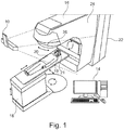
- the patient monitoring system comprises a camera system 10 which in this embodiment comprises a stereoscopic camera system that is connected by wiring (not shown) to a computer 14.
- the computer 14 is also connected to treatment apparatus 16 such as a linear accelerator for applying radiotherapy.
- treatment apparatus 16 such as a linear accelerator for applying radiotherapy.
- a mechanical couch 18 is provided as part of the treatment apparatus upon which a patient 20 lies during treatment.
- the treatment apparatus 16 and the mechanical couch 18 are arranged such that, under the control of the computer 14, the relative positions of the mechanical couch 18 and the treatment apparatus 16 may be varied, laterally, vertically, longitudinally and rotationally as is indicated in the figure by the arrows adjacent the couch.
- the treatment apparatus 16 comprises a main body 22 from which extends a gantry 24.
- a collimator 26 is provided at the end of the gantry 24 remote from the main body 22 of the treatment apparatus 16.
- the gantry 24, under the control of the computer 14 is arranged to rotate about an axis passing through the center of the main body 22 of the treatment apparatus 16. Additionally the location of irradiation by the treatment apparatus may also be varied by rotating the collimator 26 at the end of the gantry 24.
- a patient restraint in the form of a head mask 21 is used to restrain the head 19 of the patient 20 undergoing treatment.
- the camera system 10 obtains video images of the patient 20 lying on the mechanical couch 18. These video images are passed via the wiring to the computer 14.
- the computer 14 then processes the images of the patient 20 to generate a model of the surface of the patient being treated.
- the model of the surface of the patient will comprise a model of the surface of a portion of the patient's head and face.
- This model can be compared with a model of the patient generated during earlier treatment sessions.
- the difference between a current model surface and a target model surface obtained from an earlier session is identified and the positioning instructions necessary to align the surfaces are determined and sent to the mechanical couch 18.
- the computer 14 sends instructions to the treatment apparatus 16 to cause treatment to be halted until a patient 20 can be repositioned.
- a random pattern of light is projected onto the surface of the patient 20. This assists the computer 14 when identifying corresponding portions of stereoscopic images of the patient 20.
- the head mask 21 is colored so that the projected pattern of light onto the head mask 21 is not readily apparent in images obtained by the stereoscopic camera 10. This can be achieved by coloring the head mask 21 a matt black color so that the projected light is substantially absorbed by the head mask 21. Alternatively the color of the mask 21 could be selected to be substantially similar to the color of the projected light.
- Coloring the head mask 21 in this way inhibits the matching algorithm from identifying matches in the portions of the stereoscopic images corresponding to the head mask 21.
- the model generated by the computer 14 avoids incorporating portions of the surface of the head mask 21 into the model. This improves the accuracy with which a patient can be positioned since the match between the generated model and a previously stored model corresponds only to the surface of the patient 20.
- Figure 2 is a front view of a head restraint blank 21 in accordance with the present embodiment of the present invention.
- the blank 21 is also illustrated in Figure 3 which comprises a schematic perspective view of the head restraint blank 21 after deformation by a patient's head 19.
- the head mask 21 comprises a rigid U-shaped frame 28 with an integrally formed perforated sheet 30.
- the perforated sheet 30 is made from a thermoplastic which when heated can be deformed by being placed over a patient's head.
- the head mask 21 is made of any thermoplastic which is suitable for being deformed over the patient's head without causing discomfort, i.e. the thermoplastic must soften at a temperature low enough so the patient's skin is not burnt.
- Suitable thermoplastics that melt or soften at temperatures ranging from 50°C. to 100°C include poly (ethyleneadipate), poly (epsilon-caprolactone), polyvinyl stearate, cellulose acetate, butyrate and ethyl cellulose poly (propylene oxide) containing comonomers, trans polyisoprene and cis polyisoprene based thermoplastic materials, and polycaprolactone based materials.
- the head mask 21 is colored black so as to absorb a significant proportion of patterned light projected onto its surface such that the patterned light is not readily discernible in obtained images of the head mask 21.
- the head mask 21 can be colored during the molding of the thermoplastic using a suitable pigment, or post-molding using a coating. Suitable coatings will include deep-black chalkboard paint such as is used to blacken the interiors of optical telescopes to minimize stray light in the light path. If a coating is used the coating should preferably be hypoallergenic so as to minimize the risk of reaction with a patient's skin.
- the perforated sheet 30 has three large apertures comprising a main central aperture 32 and two subsidiary triangular apertures 34,36 provided either side of the main central aperture 32.
- a series of screw holes 35 are provided in the frame 28 enabling the frame 28 to be attached to a restraint platform.
- the arrangement of the apertures 32,34,36 in the perforated sheet 30 is such that when the head mask 21 is deformed by being placed over the patient's face, the perforated sheet 30 is molded and stretched to sculpt the contours of the patient's head 19 whilst leaving the patient's face, including eyes, nose and mouth, to be uncovered.
- the portions of the perforated sheet 30 between the apertures 32,34,36 are stretched so as to form a chin strap 38 and a pair of accompanying side struts 40 either side of the patient's face which together act to restrain the patient's head 19 in place whilst giving the deformed sheet 30 substantial structural rigidity thus ensuring that despite the fact that the patient's face is unenclosed, the mask acts to retain the patient's head 19 in a fixed position when it lies on a cushion 42 provided as part of a restraint platform.
- non-contact motion detection systems such as Vision RT's AlignRT RTM system such as is disclosed in US7889906 .
- the perforated sheet 30 before being deformed substantially fills the entirety of the U-shaped frame 28 with the edge 44 of the perforated sheet 30 at the open end of the U-shaped frame 28 following a serpentine curve initially running approximately perpendicularly to the arms of the frame 28 before moving away from the apex of the U-shaped frame 28 so as to provide a small additional protrusion 46 in the central portion of the sheet 30.
- this protrusion 46 is such to enable the portion of the perforated sheet 30 to form a chin strap 38 which encloses a patient's chin when the head mask 21 has been deformed.
- the main central aperture 32 comprises a central rectangular portion 48 and two adjacent wing portions 50,52 where, the central rectangular portion 48 extends across the middle third of the perforated sheet 30 with the longer sides of the central rectangular portion 48 running parallel with the arms of the U-shaped frame 28.
- the two wing portions 50,52 each comprise right angled triangular openings each with bases extending half way down the long sides of the central rectangular portion 48 and with each wing portion 50,52 having an apex level with the edge 53 of the central rectangular portion 48 remote from the edge 44 of the perforated sheet 30 half way between the long side of the central rectangular portion 48 and the edge 55 of the U-shape frame 28.
- some areas of the sheet 30 are left free of perforations. More specifically, other than in a central area 54 of the section of the sheet 30 and a band 56 immediately adjacent to the open end of the U-shaped frame 28, the portion of the sheet 30 adjacent to the open end of the U-shaped frame 28 is left free from perforations. In use this causes the central area 54 and the section of sheet 30 immediately adjacent to the open end of the U-shaped frame 28 to deform more easily and so accommodate the shape of a patient's chin. Also a band 57 of sheet 30 running across the edge of the main aperture 32 remote from the open end of the U-shaped frame 30 extending across to the arms of the frame 28 is also left free from perforations.
- the two subsidiary triangular apertures 34,36 each comprise a right-angled triangular opening.
- the two subsidiary triangular apertures 34,36 lie either side of the main central aperture 32 with a base adjacent to the arms of the U-shaped frame 28 and apex level with the end of the edge of the central rectangular portion 48 of the main central aperture 32 with the hypotenuses of the winged portions 50,52 of the main aperture 32 and the triangular apertures 34,36 being parallel to each other.
- the edges of main aperture 32 and the two subsidiary triangular apertures 34,36 define the edges of a pair of strips 58,60 of the perforated sheet 30 lying either side of the main aperture 32 connecting the U-shaped frame 28 with the portion of the sheet 30 adjacent to the open end of the U-shaped frame 28.
- these strips 58,60 are deformed so as to form the struts 40 connecting the chin strap 38 formed from the portion of the sheet 30 adjacent to the open end of the U-shaped frame 28 with a portion of the U-shaped frame 28 further from the open end of the frame 28.
- the perforated sheet 30 will resist further deformation when placed under tension.
- the lower portion of the deformed sheet 30 acts to retain a patient's head 19 in position as this portion of the sheet 30 forms a chin strap 38 which prevents movement of a patient's chin away from the plane of the U-shaped frame 28.
- the portion of the perforated sheet 30 remote from the open end of the U-shaped frame 28 prevents the forehead of a patient 20 from being moved away the plane of the U-shaped frame 28.
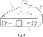
- Figure 4 is a front perspective view of a stereoscopic camera system 10 of the patient monitoring system of Figure 1 .
- the stereoscopic camera system 10 comprises a housing 64 which is connected to a bracket 66 via a hinge 68.
- the bracket 66 enables the stereoscopic camera system 10 to be attached in a fixed location to the ceiling of a treatment room whilst the hinge 68 permits the orientation of the stereoscopic camera system 10 to be orientated relative to the bracket 66 so that the stereoscopic camera system 10 is arranged to view a patient 20 on a mechanical couch 18.
- a pair of lenses 70L,70R is mounted at either end of the front surface 71 of the housing 64. These lenses 70L,70R are positioned in front of image detectors such as CMOS active pixel sensors or charge coupled devices (not shown) contained within the housing 64. The image detectors are arranged behind the lenses 70L,70R so as to capture images of a patient 20 via the lenses 70L,70R.
- the housing 64 may be made of a material such as lead which provides very good shielding from radiation and thereby reduce the extent to which energetic particles generate random errors in images obtained by the image detectors.
- a speckle projector 72 is provided in the middle of the front surface 71 of the housing 64 between the two lenses 70L,70R.
- the speckle projector 72 is arranged to illuminate a patient 20 with a pseudo random speckled pattern of infrared light so that when images of a patient 20 are captured by the two image detectors corresponding portions of captured images can be distinguished.
- the speckle projector comprises a light source such as a LED and a film with a random speckle pattern printed on the film. In use light from the light source is projected via the film and as a result a pattern consisting of light and dark areas is projected onto the surface of a patient 20.
- images of the projected speckle pattern are captured by the stereoscopic camera system 10 the images can then be processed to determine the positions of a set of points on the surface of the patient and hence the positioning of the patient can be monitored.
- Figure 5 is a schematic block diagram of the computer 14 of the patient monitor of Figure 1 .
- the computer 14 is configured by software either provided on a disc 74 or by receiving an electrical signal 76 via a communications network into a number of functional modules 78-86.
- the functional modules 78-86 illustrated in Figure 5 are purely notional in order to assist with the understanding of the working of the claimed invention and may not in certain embodiments directly correspond with blocks of code in the source code for the software. In other embodiments the functions performed by the illustrated functional modules 78-86 may be divided between different modules or may be performed by the re-use of the same modules for different functions.
- the functional modules 78-86 comprise: a 3D position determination module 78 for processing images received from the stereoscopic camera system 10, a model generation module 80 for processing data generated by the 3D position determination module 78 and converting the data into a 3D wire mesh model of an imaged surface; a generated model store 82 for storing a 3D wire mesh model of an imaged surface; a target model store 84 for storing a previously generated 3D wire mesh model; and a matching module 86 for determining rotations and translations required to match a generated model with a target model;
- these images are processed by the 3D position determination module 78.
- This processing enables the 3D position determination module 78 to identify 3D positions of points on the surface of a patient 20. This is achieved by the 3D position determination module 78 identifying corresponding points in pairs of images obtained by the lenses 70L,70R of the stereoscopic camera system 10 and then determining 3D positions for those points based on the relative positions of corresponding points in obtained pairs of images and stored data identifying the relative positions of cameras obtaining the images.
- the stereoscopic camera system 10 includes a speckle projector 72 arranged to project a pseudo-random speckle pattern onto the patient 20 being imaged so that different portions of the surface of the patient 20 can be more easily distinguished.
- the size of the speckle pattern is selected so that different patterns will be apparent in different image patches.
- Figure 6 is an illustrative example of an image captured by the stereoscopic camera system 10 of the head of mannequin enclosed by a head mask 21 onto which a speckle pattern is projected.
- the speckle pattern is visible in the portions of the image corresponding to the face of the mannequin.
- the speckle pattern is not visible.
- the position data generated by the 3D position determination module 78 is then passed to the model generation module 80 which processes the position data to generate a 3D wire mesh model of the surface of a patient 20 imaged by the stereoscopic cameras 10.
- the 3D position determination module 78 is less likely to be able to identify corresponding portions in the stereoscopic images obtained by the stereoscopic camera 10 for these regions of the image and hence these areas are less likely to be included in a 3D wire mesh model generated by the model generation module 80.
- the 3D model comprises a triangulated wire mesh model where the vertices of the model correspond to the 3D positions determined by the 3D position determination module 78.
- the generated model store 82 When such a model has been determined it is stored in the generated model store 82.
- Figure 7 is an illustrative example of a 3D position data and a generated wire 3D wire mesh model corresponding to a front view of the mannequin shown in Figure 6 .
- individual 3D position points are shown as individual dots whereas in the central portion of the image where the density of 3D position data exceeds a threshold, the model is shown as a continuous surface.
- the matching module 86 is then invoked to determine a matching translation and rotation between the generated model based on the current images being obtained by the stereoscopic cameras 10 and a previously generated model surface of the patient stored in the target model store 84.
- the determined translation and rotation can then be sent as instructions to the mechanical couch 18 to cause the couch to position the patient 20 in the same position relative to the treatment apparatus 16 as they were when they were previously treated.
- the stereoscopic cameras 10 can continue to monitor the patient 20 and any variation in position can be identified by generating further model surfaces and comparing those generated surfaces with the target model stored in the target model store 84. If it is determined that a patient has moved out of position, the treatment apparatus 16 can be halted and the patient 20 repositioned, thereby avoiding irradiating the wrong parts of the patient 20.
- the head mask 21 being colored black
- the head mask 21 could be of any color which absorbs light corresponding in color to the projected speckle pattern or other projected light or otherwise reduces the visibility of the projected speckle pattern or other projected light in images captured by the stereoscopic camera 10.
- a head mask 21 might be colored red so as to match the color of the speckle pattern or other light projected onto the surface of patient.
- thermoplastic head masks 21 for restraining a patient 20 during stereotactic brain surgery
- the present invention also extends to and is equally applicable to other forms of restraint for use in relation any form of treatment such as radiotherapy or the like where high accuracy of patient positioning is required.
- restraints will include full body restraints which mold to the shape of a patient to fix a patient relative to a positioning couch and other types of restraint which are molded to the surface of a patient and set so as to limit patient motion or to cause a patient to adopt a specified pose or orientation. In all such cases such restraints may be colored so as to reduce the generation of matches by a patient monitoring system.
- a head mask 21 which is colored black, it will also be appreciated that in other embodiments only a portion of the restraint might be colored.
- the processing module could then be arranged to limit the generation of a 3D wire mesh model to points within the boundary.
- a restraint will be substantially dull and nonreflective so as to minimize specular highlights which might appear in images of the restraint which may be matched.
- a restraint will be designed so as to avoid having features of a size corresponding to the size of image patch used to identify corresponding features in stereoscopic image.
- the size of holes or perforations will be selected so as to be of a different size to the size of features matched in an image.
- a head mask in which the color of the head mask 21 is selected so as to impede the ability of a 3D position determination module 78 to identify corresponding portions of stereoscopic images
- the color of the restraint might be selected to be such to be easily detectable within images and the 3D position determination module 78 might be arranged to identify such sections of images and ignore such colored sections when attempting to identify matches.
- the restraint or a portion of the restraint adjacent the area of the patient being imaged, might be colored in an easily distinguishable color, for example, green.
- the captured images will also include portions of the restraint which will be easily identifiable by the color or range of colors of the pixels making up the image corresponding to the specific identifiable color of the restraint.
- the 3D position determination module 78 could then be arranged so as not to process pixels of the identified color or range of colors corresponding to the head mask 21 when attempting to identify corresponding portions of stereoscopic images.
- a combination of image processing can take place where images of the colored restraint are not matched because the projected light is either absorbed to the extent that the images are not readily apparent, or the absorbtion by the restraint is such that the images are still apparent and the color of the restraint enables the images to be distinguished from the images of the patient and therefore not matched by the 3D position determination module 78.
- the patient restraint might have a distinguishable pattern to further aid or enable distinction between images of the patient and the patient restraint and the prevention of matching.
- the monitoring system could generate a model in a conventional way and instead utilize the color of the restraint to identify portions of a model which correspond to the surface of a patient and only utilize those portions of a model to monitor the position of a patient.
- an additional color camera might be included in the stereoscopic camera system 10 used to monitor a patient.
- image data captured by the additional color camera could then be utilized to texture render the generated model.
- the texture rendered model could then be further processed by removing portions of the model which correspond to the color of the restraint so that the remaining portion of the model corresponded to a portion of the surface of the patient being monitored and this model could then be utilized to position the patient for treatment.
- the model generation module could then utilize the color of the colored restraint to identify portions of an image corresponding to a restraint and avoid utilizing such portions of an image to generate a model of the surface of a patient or alternatively could use the identified color of portions of images to identify portions of a model corresponding to a restraint and avoid using such portions of a model when monitoring for movement of a patient.
- structured light might be used e.g. for example a grid pattern might be projected onto the surface of the patient and the computer 14 may be arranged to generate a model of the surface of a patient 20 on the basis of the distortion of the light pattern.
- the camera system 10 may not be a stereoscopic camera system.
- the above described embodiments enable positioning of the patient with greater accuracy by generating a model of the patient without matching images of the patient restraint.
- This is achieved in alternative ways, either by physically preventing the patient restraint from being imaged by making it from a color that substantially absorbs the projected light, or using a distinguishably colored patient restraint and processing the images of the portion of the patient being monitored such that the images of the patient restraint are not matched or by texture rendering the portion of the patient being monitored using image data from an additional camera and removing the portions of model corresponding in color to the color of a restraint prior to utilizing the model to position a patient.
Landscapes
- Engineering & Computer Science (AREA)
- Health & Medical Sciences (AREA)
- Physics & Mathematics (AREA)
- Biomedical Technology (AREA)
- Life Sciences & Earth Sciences (AREA)
- General Physics & Mathematics (AREA)
- Theoretical Computer Science (AREA)
- Computer Vision & Pattern Recognition (AREA)
- Nuclear Medicine, Radiotherapy & Molecular Imaging (AREA)
- General Health & Medical Sciences (AREA)
- Animal Behavior & Ethology (AREA)
- Pathology (AREA)
- Veterinary Medicine (AREA)
- Public Health (AREA)
- Surgery (AREA)
- Radiology & Medical Imaging (AREA)
- Medical Informatics (AREA)
- Oral & Maxillofacial Surgery (AREA)
- Molecular Biology (AREA)
- Heart & Thoracic Surgery (AREA)
- Neurosurgery (AREA)
- Optics & Photonics (AREA)
- Quality & Reliability (AREA)
- Radiation-Therapy Devices (AREA)
Claims (13)
- Patientenüberwachungssystem, mit:einem Projektor (72), der zur Projektion eines Lichtmusters auf einen Patienten (20) betreibbar ist, der sich einer Behandlung unterzieht;einer Patientenhalteeinrichtung (21), die zum Halten eines Patienten relativ zu einer Behandlungsvorrichtung (16) betreibbar ist;einem Kamerasystem (10), das zur Erlangung von Bildern des Patienten und der Patientenhalteeinrichtung betreibbar ist; undeinem Modellerzeugungsmodul (80), das zur Verarbeitung der durch das Kamerasystem (10) erlangten Bilder zur Erzeugung eines Modells der Oberfläche eines Abschnitts eines in den Bildern erscheinenden Patienten betreibbar ist;dadurch gekennzeichnet, dass zumindest ein Abschnitt der Patientenhalteeinrichtung (21) derart eingefärbt ist, dass ein projiziertes Lichtmuster, das von dem Projektor (72) auf eine Oberfläche der Patientenhalteeinrichtung projiziert wird, im Wesentlichen von der Patientenhalteeinrichtung derart absorbiert wird, dass es in dem der Patientenhalteeinrichtung entsprechenden Abschnitt der erlangten Bilder nicht leicht sichtbar ist.
- Patientenüberwachungssystem nach Anspruch 1, wobei das Kamerasystem (10) umfasst
ein stereoskopisches Kamerasystem; und der Projektor einen Speckle-Projektor (72) umfasst, der zur Projektion eines pseudozufälligen Lichtmusters auf die Oberfläche eines zu überwachenden Patienten betreibbar ist. - Patientenüberwachungssystem nach Anspruch 2, wobei die Struktur der Halteeinrichtung (21) derart ist, dass Löcher und Perforationen in der Halteeinrichtung, die in durch das Kamerasystem (10) erlangten Bildern der Halteeinrichtung erscheinen, von verschiedener Größe in Bezug auf Abschnitte eines auf die Halteeinrichtung projizierten Lichtmusters sind, das von dem Modellerzeugungsmodul zur Identifizierung entsprechender Abschnitte stereoskopischer Bilder verwendet wird.
- Patientenüberwachungssystem nach Anspruch 1, wobei der Projektor dazu betreibbar ist, ein strukturiertes Licht auf einen Patienten zu projizieren, der sich einer Behandlung unterzieht.
- Patientenüberwachungssystem, mit:einem Projektor (72), der zur Projektion eines Lichtmusters auf einen Patienten betreibbar ist, der sich einer Behandlung unterzieht;einer Patientenhalteeinrichtung, die zum Halten eines Patienten relativ zu einer Behandlungsvorrichtung betreibbar ist;einem Kamerasystem (10), das zur Erlangung von Bildern des Patienten und der Patientenhalteeinrichtung betreibbar ist; undeinem Modellerzeugungsmodul (80), das zur Verarbeitung der durch das Kamerasystem (10) erlangten Bilder betreibbar ist, um ein Modell der Oberfläche eines Abschnitts eines in den Bildern erscheinenden Patienten zu erzeugen;dadurch gekennzeichnet, dass zumindest ein Abschnitt der Patientenhalteeinrichtung eingefärbt ist, und das Modellerzeugungsmodul zur Verarbeitung von durch das Kamerasystem erlangten Bildern zur Identifizierung von der Farbe der eingefärbten Patientenhalteeinrichtung entsprechenden Abschnitten der Bilder und zur Vermeidung einer Verwendung der identifizierten Abschnitte der Bilder betreibbar ist, die der Farbe der eingefärbten Patientenhalteeinrichtung entsprechen, um ein Modell der Oberfläche eines Abschnitts eines in den Bildern erscheinenden Patienten zu erzeugen.
- Patientenüberwachungssystem nach Anspruch 5, wobei das Modellerzeugungsmodul zur Verarbeitung von durch das Kamerasystem erlangten Bildern zur Erzeugung eines Modells der Oberfläche eines Abschnitts eines in den Bildern erscheinenden Patienten betreibbar ist; zur Verarbeitung der weiteren Bilder zu einer texturierten Widergabe des erzeugten Modells des Abschnitts des Patienten;
und zur Überwachung der Position eines Patienten auf der Grundlage des Abschnitts des erzeugten Modells, der keine texturierte Widergabe mit einer Farbe ist, die der Farbe der Patientenhalteeinrichtung entspricht. - Patientenüberwachungssystem nach Anspruch 6, wobei das Patientenüberwachungssystem zum Vergleich des Abschnitts des erzeugten Modells, der keine texturierte Widergabe mit einer der Farbe der Patientenhalteeinrichtung entsprechenden Farbe ist, mit einem gespeicherten Modell der Oberfläche eines Patienten und zur Erzeugung von Positionierungsanweisungen betreibbar ist, um den Abschnitt des erzeugten Modells mit dem gespeicherten Modell abzustimmen.
- Patientenüberwachungssystem nach Anspruch 6, wobei der eingefärbte Abschnitt der Patientenhalteeinrichtung gemustert ist, und das Patientenüberwachungssystem dazu eingerichtet ist, Abschnitte eines erzeugten Modells zu identifizieren, die mit dem Muster texturiert widergegeben sind, das dem auf dem eingefärbten Abschnitt der Patientenhalteeinrichtung erscheinenden Muster entspricht.
- Patientenüberwachungssystem nach Anspruch 6, wobei der eingefärbte Abschnitt der Patientenhalteeinrichtung ein Rand um eine Öffnung in der Halteeinrichtung ist, und das Patientenüberwachungssystem dazu eingerichtet ist, die Position eines Patienten auf der Grundlage des Abschnitts des erzeugten Modells zu überwachen, der innerhalb der Sektion eines Modells enthalten ist, die mit einer Farbe texturiert wiedergegeben ist, die dem eingefärbten Rand entspricht.
- Patientenüberwachungssystem nach einem der vorstehenden Ansprüche, wobei der farbige Teil der Patientenhalteeinrichtung schwarz eingefärbt ist.
- Patientenüberwachungssystem nach einem der vorstehenden Ansprüche, wobei der eingefärbte Abschnitt der Halteeinrichtung einen Thermoplast umfasst.
- Patientenüberwachungssystem nach einem der vorstehenden Ansprüche, wobei die Oberfläche der Halteeinrichtung ein geringes Reflexionsvermögen aufweist.
- Patientenüberwachungssystem nach einem der vorstehenden Ansprüche, wobei die Halteeinrichtung eine Kopfmaske umfasst.
Priority Applications (2)
| Application Number | Priority Date | Filing Date | Title |
|---|---|---|---|
| EP19156000.2A EP3593859B1 (de) | 2016-04-13 | 2017-04-10 | Patientenüberwachungssystem |
| EP21161546.3A EP3875148A1 (de) | 2016-04-13 | 2017-04-10 | Patientenüberwachungssystem |
Applications Claiming Priority (2)
| Application Number | Priority Date | Filing Date | Title |
|---|---|---|---|
| US15/098,094 US9789338B1 (en) | 2016-04-13 | 2016-04-13 | Patient monitoring system |
| PCT/GB2017/051003 WO2017178804A1 (en) | 2016-04-13 | 2017-04-10 | A patient monitoring system |
Related Child Applications (3)
| Application Number | Title | Priority Date | Filing Date |
|---|---|---|---|
| EP19156000.2A Division EP3593859B1 (de) | 2016-04-13 | 2017-04-10 | Patientenüberwachungssystem |
| EP19156000.2A Division-Into EP3593859B1 (de) | 2016-04-13 | 2017-04-10 | Patientenüberwachungssystem |
| EP21161546.3A Division EP3875148A1 (de) | 2016-04-13 | 2017-04-10 | Patientenüberwachungssystem |
Publications (2)
| Publication Number | Publication Date |
|---|---|
| EP3247458A1 EP3247458A1 (de) | 2017-11-29 |
| EP3247458B1 true EP3247458B1 (de) | 2019-03-13 |
Family
ID=58692525
Family Applications (3)
| Application Number | Title | Priority Date | Filing Date |
|---|---|---|---|
| EP21161546.3A Pending EP3875148A1 (de) | 2016-04-13 | 2017-04-10 | Patientenüberwachungssystem |
| EP17722495.3A Active EP3247458B1 (de) | 2016-04-13 | 2017-04-10 | Patientenüberwachungssystem |
| EP19156000.2A Active EP3593859B1 (de) | 2016-04-13 | 2017-04-10 | Patientenüberwachungssystem |
Family Applications Before (1)
| Application Number | Title | Priority Date | Filing Date |
|---|---|---|---|
| EP21161546.3A Pending EP3875148A1 (de) | 2016-04-13 | 2017-04-10 | Patientenüberwachungssystem |
Family Applications After (1)
| Application Number | Title | Priority Date | Filing Date |
|---|---|---|---|
| EP19156000.2A Active EP3593859B1 (de) | 2016-04-13 | 2017-04-10 | Patientenüberwachungssystem |
Country Status (6)
| Country | Link |
|---|---|
| US (2) | US9789338B1 (de) |
| EP (3) | EP3875148A1 (de) |
| JP (1) | JP6847125B2 (de) |
| CN (2) | CN109069862B (de) |
| GB (1) | GB2553026B (de) |
| WO (1) | WO2017178804A1 (de) |
Cited By (1)
| Publication number | Priority date | Publication date | Assignee | Title |
|---|---|---|---|---|
| EP3557531B1 (de) * | 2018-04-18 | 2026-04-01 | Vision RT Limited | Kameraüberwachungssystem zur überwachung eines patienten in einem bohrungsbasierten medizinischen system |
Families Citing this family (11)
| Publication number | Priority date | Publication date | Assignee | Title |
|---|---|---|---|---|
| US20180235554A1 (en) * | 2017-02-16 | 2018-08-23 | Eric A Burgett | Patient-Specific Restraining Device and Integrated Dosimetry System |
| US20180311512A1 (en) | 2017-04-28 | 2018-11-01 | C-Rad Positioning Ab | Patient monitoring |
| US11590364B2 (en) * | 2017-07-21 | 2023-02-28 | Varian Medical Systems International Ag | Material inserts for radiation therapy |
| US11712579B2 (en) * | 2017-07-21 | 2023-08-01 | Varian Medical Systems, Inc. | Range compensators for radiation therapy |
| US11182954B2 (en) * | 2018-09-07 | 2021-11-23 | Hivemapper Inc. | Generating three-dimensional geo-registered maps from image data |
| CN109498053A (zh) * | 2019-01-23 | 2019-03-22 | 中国人民解放军陆军特色医学中心 | 一种pet检查头部固定装置 |
| US11986032B2 (en) * | 2019-11-15 | 2024-05-21 | The Moses H. Cone Memorial Hospital Operating Corporation | Method of clothed treatment during radiation therapy and garment for same |
| CA3207401A1 (en) | 2021-02-11 | 2022-08-18 | James L. Robar | Patient-specific immobilization structure and system and method for fabrication thereof |
| CN114452546B (zh) * | 2021-09-26 | 2025-01-03 | 西安大医集团股份有限公司 | 放疗监测系统及其控制方法 |
| EP4385449A1 (de) | 2022-12-16 | 2024-06-19 | Caranx Medical SAS | System und computersystem zur positionierung eines moduls |
| US20240416147A1 (en) | 2023-06-14 | 2024-12-19 | Vision Rt Limited | Hybrid continuous positive pressure and surface imaging system and method |
Family Cites Families (34)
| Publication number | Priority date | Publication date | Assignee | Title |
|---|---|---|---|---|
| DE10031074A1 (de) | 2000-06-30 | 2002-01-31 | Schwerionenforsch Gmbh | Vorrichtung zur Bestrahlung eines Tumorgewebes |
| WO2003061477A1 (en) | 2002-01-23 | 2003-07-31 | Med-Tec Iowa, Inc. | Hermoplastic patient restraint member for radiation therapy |
| GB2390792B (en) | 2002-07-08 | 2005-08-31 | Vision Rt Ltd | Image processing system for use with a patient positioning device |
| US20040053237A1 (en) * | 2002-09-13 | 2004-03-18 | Yingjie Liu | Microfluidic channels with attached biomolecules |
| EP1545364B1 (de) | 2002-10-04 | 2006-04-12 | Med-Tec Iowa, Inc. | Verstärkte thermoplastische patientenhalterung für radiotherapie |
| US20040159325A1 (en) * | 2003-02-19 | 2004-08-19 | Med-Tec | Indexing system for radiation therapy |
| RU2245096C1 (ru) * | 2003-06-17 | 2005-01-27 | Голубцов Константин Васильевич | Способ диагностики дефектов зрения и устройство для его осуществления |
| CN1522674A (zh) * | 2003-09-04 | 2004-08-25 | 高春平 | 可重复定位的躯干部立体定位方法和装置 |
| GB2464856B (en) | 2004-09-24 | 2010-06-30 | Vision Rt Ltd | Image processing system for use with a patient positioning device |
| US7379531B2 (en) * | 2005-06-13 | 2008-05-27 | Siemens Medical Solutions Health Services Corporation | Beam therapy treatment user interface monitoring and recording system |
| CN101282760A (zh) * | 2005-08-11 | 2008-10-08 | 纳沃特克医药有限公司 | 利用基于放射性的位置传感器的医疗系统和方法 |
| GB2455926B (en) * | 2006-01-30 | 2010-09-01 | Axellis Ltd | Method of preparing a medical restraint |
| JP4651591B2 (ja) * | 2006-08-17 | 2011-03-16 | 三菱電機株式会社 | 位置決め装置 |
| WO2009086332A1 (en) * | 2007-12-21 | 2009-07-09 | Koning Corporation | The methods and apparatus of cone beam ct imaging and image-guided procedures |
| WO2015187620A1 (en) * | 2014-06-02 | 2015-12-10 | The Trustees Of Dartmouth College | Surgical navigation with stereovision and associated methods |
| US7729473B2 (en) * | 2008-07-29 | 2010-06-01 | Elekta Ab (Publ) | Image-guided multi-source radiotherapy |
| WO2010063008A2 (en) * | 2008-11-26 | 2010-06-03 | Oregon Health & Science University | Head and neck radiation localization using oral appliance |
| GB2467160B (en) | 2009-01-26 | 2011-12-14 | Vision Rt Ltd | A blank for a head restraint |
| DE102009034823B4 (de) * | 2009-07-27 | 2014-02-27 | Schreiner Group Gmbh & Co. Kg | Etikett, Verwendung eines erhabenen Strukturmerkmals, Injektionsvorrichtung und Verfahren zur Herstellung eines Etiketts |
| US8235530B2 (en) * | 2009-12-07 | 2012-08-07 | C-Rad Positioning Ab | Object positioning with visual feedback |
| US8805048B2 (en) * | 2010-04-01 | 2014-08-12 | Mark Batesole | Method and system for orthodontic diagnosis |
| EP2568882B1 (de) * | 2010-05-12 | 2017-09-13 | Trophy | Ausrichtungsvorrichtung für intraorales zahnröntgen |
| WO2013155388A1 (en) * | 2012-04-12 | 2013-10-17 | University Of Florida Research Foundation, Inc. | Ambiguity-free optical tracking system |
| GB2501308A (en) * | 2012-04-19 | 2013-10-23 | Vision Rt Ltd | Matching the position of an object to a target model using rigid transformations |
| GB2549022B (en) | 2012-04-26 | 2017-11-29 | Vision Rt Ltd | A method of determining the 3D positions of points on the surface of an object |
| WO2013185087A1 (en) * | 2012-06-07 | 2013-12-12 | The Trustees Of Dartmouth College | Methods and systems for intraoperative tumor margin assessment in surgical cavities and resected tissue specimens |
| EP2687159B1 (de) * | 2012-07-20 | 2016-06-29 | Deutschmann, Heinrich | Patientenpositionierungs- und Abbildungssystem |
| WO2014024115A1 (en) * | 2012-08-09 | 2014-02-13 | Koninklijke Philips N.V. | System and method for radiotherapeutic treatment |
| GB2506903A (en) * | 2012-10-12 | 2014-04-16 | Vision Rt Ltd | Positioning patient for radio-therapy using 3D models and reflective markers |
| KR102093533B1 (ko) * | 2013-05-16 | 2020-03-25 | 주식회사 쿠라레 | 메타크릴 수지 조성물 및 그 성형체 |
| RU2677765C2 (ru) * | 2013-07-10 | 2019-01-21 | Конинклейке Филипс Н.В. | Система для скрининга состояния оксигенации субъекта |
| ES2666346T3 (es) * | 2013-11-08 | 2018-05-04 | Reginald Nieberding | Kit para la inmovilización de una parte del cuerpo de un ser humano |
| WO2015191605A1 (en) * | 2014-06-09 | 2015-12-17 | The Johns Hopkins University | Virtual rigid body optical tracking system and method |
| GB201420950D0 (en) * | 2014-11-25 | 2015-01-07 | Sck Cen | Mask for radiation dosimetry |
-
2016
- 2016-04-13 US US15/098,094 patent/US9789338B1/en active Active
-
2017
- 2017-04-10 EP EP21161546.3A patent/EP3875148A1/de active Pending
- 2017-04-10 EP EP17722495.3A patent/EP3247458B1/de active Active
- 2017-04-10 CN CN201780023071.5A patent/CN109069862B/zh active Active
- 2017-04-10 EP EP19156000.2A patent/EP3593859B1/de active Active
- 2017-04-10 GB GB1709809.6A patent/GB2553026B/en active Active
- 2017-04-10 CN CN202110314283.7A patent/CN113198113B/zh active Active
- 2017-04-10 WO PCT/GB2017/051003 patent/WO2017178804A1/en not_active Ceased
- 2017-04-10 JP JP2018552709A patent/JP6847125B2/ja active Active
- 2017-09-07 US US15/698,034 patent/US10441818B2/en active Active
Non-Patent Citations (1)
| Title |
|---|
| None * |
Cited By (1)
| Publication number | Priority date | Publication date | Assignee | Title |
|---|---|---|---|---|
| EP3557531B1 (de) * | 2018-04-18 | 2026-04-01 | Vision RT Limited | Kameraüberwachungssystem zur überwachung eines patienten in einem bohrungsbasierten medizinischen system |
Also Published As
| Publication number | Publication date |
|---|---|
| GB2553026B (en) | 2018-09-19 |
| EP3593859A1 (de) | 2020-01-15 |
| US20170296845A1 (en) | 2017-10-19 |
| GB201709809D0 (en) | 2017-08-02 |
| US20170368370A1 (en) | 2017-12-28 |
| US9789338B1 (en) | 2017-10-17 |
| CN113198113B (zh) | 2023-09-15 |
| EP3247458A1 (de) | 2017-11-29 |
| EP3875148A1 (de) | 2021-09-08 |
| US10441818B2 (en) | 2019-10-15 |
| CN109069862A (zh) | 2018-12-21 |
| JP6847125B2 (ja) | 2021-03-24 |
| EP3593859B1 (de) | 2021-05-19 |
| WO2017178804A1 (en) | 2017-10-19 |
| JP2019511316A (ja) | 2019-04-25 |
| GB2553026A (en) | 2018-02-21 |
| CN113198113A (zh) | 2021-08-03 |
| CN109069862B (zh) | 2021-04-27 |
Similar Documents
| Publication | Publication Date | Title |
|---|---|---|
| EP3247458B1 (de) | Patientenüberwachungssystem | |
| US12121751B2 (en) | Patient monitor | |
| US7348974B2 (en) | Image processing system for use with a patient positioning device | |
| EP3294414B1 (de) | System zur überwachung der strahlungsdosierung | |
| CN106999727B (zh) | 标定用于放射治疗设备的患者监测系统的方法 | |
| JP7156824B2 (ja) | 患者モニタリングシステム | |
| JP5274526B2 (ja) | 皮膚線量表示装置及び皮膚線量表示方法 | |
| CN111052186B (zh) | 患者监测系统生成的模型的准确度的测量方法和设备 |
Legal Events
| Date | Code | Title | Description |
|---|---|---|---|
| STAA | Information on the status of an ep patent application or granted ep patent |
Free format text: STATUS: UNKNOWN |
|
| STAA | Information on the status of an ep patent application or granted ep patent |
Free format text: STATUS: EXAMINATION IS IN PROGRESS |
|
| PUAI | Public reference made under article 153(3) epc to a published international application that has entered the european phase |
Free format text: ORIGINAL CODE: 0009012 |
|
| 17P | Request for examination filed |
Effective date: 20170620 |
|
| AK | Designated contracting states |
Kind code of ref document: A1 Designated state(s): AL AT BE BG CH CY CZ DE DK EE ES FI FR GB GR HR HU IE IS IT LI LT LU LV MC MK MT NL NO PL PT RO RS SE SI SK SM TR |
|
| AX | Request for extension of the european patent |
Extension state: BA ME |
|
| GRAJ | Information related to disapproval of communication of intention to grant by the applicant or resumption of examination proceedings by the epo deleted |
Free format text: ORIGINAL CODE: EPIDOSDIGR1 |
|
| STAA | Information on the status of an ep patent application or granted ep patent |
Free format text: STATUS: GRANT OF PATENT IS INTENDED |
|
| GRAP | Despatch of communication of intention to grant a patent |
Free format text: ORIGINAL CODE: EPIDOSNIGR1 |
|
| DAV | Request for validation of the european patent (deleted) | ||
| DAX | Request for extension of the european patent (deleted) | ||
| INTG | Intention to grant announced |
Effective date: 20181001 |
|
| GRAS | Grant fee paid |
Free format text: ORIGINAL CODE: EPIDOSNIGR3 |
|
| GRAA | (expected) grant |
Free format text: ORIGINAL CODE: 0009210 |
|
| STAA | Information on the status of an ep patent application or granted ep patent |
Free format text: STATUS: THE PATENT HAS BEEN GRANTED |
|
| AK | Designated contracting states |
Kind code of ref document: B1 Designated state(s): AL AT BE BG CH CY CZ DE DK EE ES FI FR GB GR HR HU IE IS IT LI LT LU LV MC MK MT NL NO PL PT RO RS SE SI SK SM TR |
|
| REG | Reference to a national code |
Ref country code: GB Ref legal event code: FG4D |
|
| REG | Reference to a national code |
Ref country code: CH Ref legal event code: EP Ref country code: AT Ref legal event code: REF Ref document number: 1106900 Country of ref document: AT Kind code of ref document: T Effective date: 20190315 |
|
| REG | Reference to a national code |
Ref country code: IE Ref legal event code: FG4D |
|
| REG | Reference to a national code |
Ref country code: DE Ref legal event code: R096 Ref document number: 602017002725 Country of ref document: DE |
|
| REG | Reference to a national code |
Ref country code: SE Ref legal event code: TRGR |
|
| REG | Reference to a national code |
Ref country code: NL Ref legal event code: MP Effective date: 20190313 |
|
| REG | Reference to a national code |
Ref country code: LT Ref legal event code: MG4D |
|
| PG25 | Lapsed in a contracting state [announced via postgrant information from national office to epo] |
Ref country code: NO Free format text: LAPSE BECAUSE OF FAILURE TO SUBMIT A TRANSLATION OF THE DESCRIPTION OR TO PAY THE FEE WITHIN THE PRESCRIBED TIME-LIMIT Effective date: 20190613 Ref country code: FI Free format text: LAPSE BECAUSE OF FAILURE TO SUBMIT A TRANSLATION OF THE DESCRIPTION OR TO PAY THE FEE WITHIN THE PRESCRIBED TIME-LIMIT Effective date: 20190313 Ref country code: LT Free format text: LAPSE BECAUSE OF FAILURE TO SUBMIT A TRANSLATION OF THE DESCRIPTION OR TO PAY THE FEE WITHIN THE PRESCRIBED TIME-LIMIT Effective date: 20190313 |
|
| PG25 | Lapsed in a contracting state [announced via postgrant information from national office to epo] |
Ref country code: GR Free format text: LAPSE BECAUSE OF FAILURE TO SUBMIT A TRANSLATION OF THE DESCRIPTION OR TO PAY THE FEE WITHIN THE PRESCRIBED TIME-LIMIT Effective date: 20190614 Ref country code: NL Free format text: LAPSE BECAUSE OF FAILURE TO SUBMIT A TRANSLATION OF THE DESCRIPTION OR TO PAY THE FEE WITHIN THE PRESCRIBED TIME-LIMIT Effective date: 20190313 Ref country code: HR Free format text: LAPSE BECAUSE OF FAILURE TO SUBMIT A TRANSLATION OF THE DESCRIPTION OR TO PAY THE FEE WITHIN THE PRESCRIBED TIME-LIMIT Effective date: 20190313 Ref country code: LV Free format text: LAPSE BECAUSE OF FAILURE TO SUBMIT A TRANSLATION OF THE DESCRIPTION OR TO PAY THE FEE WITHIN THE PRESCRIBED TIME-LIMIT Effective date: 20190313 Ref country code: BG Free format text: LAPSE BECAUSE OF FAILURE TO SUBMIT A TRANSLATION OF THE DESCRIPTION OR TO PAY THE FEE WITHIN THE PRESCRIBED TIME-LIMIT Effective date: 20190613 Ref country code: RS Free format text: LAPSE BECAUSE OF FAILURE TO SUBMIT A TRANSLATION OF THE DESCRIPTION OR TO PAY THE FEE WITHIN THE PRESCRIBED TIME-LIMIT Effective date: 20190313 |
|
| REG | Reference to a national code |
Ref country code: AT Ref legal event code: MK05 Ref document number: 1106900 Country of ref document: AT Kind code of ref document: T Effective date: 20190313 |
|
| PG25 | Lapsed in a contracting state [announced via postgrant information from national office to epo] |
Ref country code: AL Free format text: LAPSE BECAUSE OF FAILURE TO SUBMIT A TRANSLATION OF THE DESCRIPTION OR TO PAY THE FEE WITHIN THE PRESCRIBED TIME-LIMIT Effective date: 20190313 Ref country code: CZ Free format text: LAPSE BECAUSE OF FAILURE TO SUBMIT A TRANSLATION OF THE DESCRIPTION OR TO PAY THE FEE WITHIN THE PRESCRIBED TIME-LIMIT Effective date: 20190313 Ref country code: ES Free format text: LAPSE BECAUSE OF FAILURE TO SUBMIT A TRANSLATION OF THE DESCRIPTION OR TO PAY THE FEE WITHIN THE PRESCRIBED TIME-LIMIT Effective date: 20190313 Ref country code: SK Free format text: LAPSE BECAUSE OF FAILURE TO SUBMIT A TRANSLATION OF THE DESCRIPTION OR TO PAY THE FEE WITHIN THE PRESCRIBED TIME-LIMIT Effective date: 20190313 Ref country code: PT Free format text: LAPSE BECAUSE OF FAILURE TO SUBMIT A TRANSLATION OF THE DESCRIPTION OR TO PAY THE FEE WITHIN THE PRESCRIBED TIME-LIMIT Effective date: 20190713 Ref country code: EE Free format text: LAPSE BECAUSE OF FAILURE TO SUBMIT A TRANSLATION OF THE DESCRIPTION OR TO PAY THE FEE WITHIN THE PRESCRIBED TIME-LIMIT Effective date: 20190313 Ref country code: RO Free format text: LAPSE BECAUSE OF FAILURE TO SUBMIT A TRANSLATION OF THE DESCRIPTION OR TO PAY THE FEE WITHIN THE PRESCRIBED TIME-LIMIT Effective date: 20190313 Ref country code: IT Free format text: LAPSE BECAUSE OF FAILURE TO SUBMIT A TRANSLATION OF THE DESCRIPTION OR TO PAY THE FEE WITHIN THE PRESCRIBED TIME-LIMIT Effective date: 20190313 |
|
| PG25 | Lapsed in a contracting state [announced via postgrant information from national office to epo] |
Ref country code: SM Free format text: LAPSE BECAUSE OF FAILURE TO SUBMIT A TRANSLATION OF THE DESCRIPTION OR TO PAY THE FEE WITHIN THE PRESCRIBED TIME-LIMIT Effective date: 20190313 Ref country code: PL Free format text: LAPSE BECAUSE OF FAILURE TO SUBMIT A TRANSLATION OF THE DESCRIPTION OR TO PAY THE FEE WITHIN THE PRESCRIBED TIME-LIMIT Effective date: 20190313 |
|
| REG | Reference to a national code |
Ref country code: DE Ref legal event code: R097 Ref document number: 602017002725 Country of ref document: DE |
|
| REG | Reference to a national code |
Ref country code: BE Ref legal event code: MM Effective date: 20190430 |
|
| PG25 | Lapsed in a contracting state [announced via postgrant information from national office to epo] |
Ref country code: IS Free format text: LAPSE BECAUSE OF FAILURE TO SUBMIT A TRANSLATION OF THE DESCRIPTION OR TO PAY THE FEE WITHIN THE PRESCRIBED TIME-LIMIT Effective date: 20190713 Ref country code: AT Free format text: LAPSE BECAUSE OF FAILURE TO SUBMIT A TRANSLATION OF THE DESCRIPTION OR TO PAY THE FEE WITHIN THE PRESCRIBED TIME-LIMIT Effective date: 20190313 Ref country code: LU Free format text: LAPSE BECAUSE OF NON-PAYMENT OF DUE FEES Effective date: 20190410 |
|
| PLBE | No opposition filed within time limit |
Free format text: ORIGINAL CODE: 0009261 |
|
| STAA | Information on the status of an ep patent application or granted ep patent |
Free format text: STATUS: NO OPPOSITION FILED WITHIN TIME LIMIT |
|
| PG25 | Lapsed in a contracting state [announced via postgrant information from national office to epo] |
Ref country code: MC Free format text: LAPSE BECAUSE OF FAILURE TO SUBMIT A TRANSLATION OF THE DESCRIPTION OR TO PAY THE FEE WITHIN THE PRESCRIBED TIME-LIMIT Effective date: 20190313 Ref country code: DK Free format text: LAPSE BECAUSE OF FAILURE TO SUBMIT A TRANSLATION OF THE DESCRIPTION OR TO PAY THE FEE WITHIN THE PRESCRIBED TIME-LIMIT Effective date: 20190313 |
|
| 26N | No opposition filed |
Effective date: 20191216 |
|
| PG25 | Lapsed in a contracting state [announced via postgrant information from national office to epo] |
Ref country code: SI Free format text: LAPSE BECAUSE OF FAILURE TO SUBMIT A TRANSLATION OF THE DESCRIPTION OR TO PAY THE FEE WITHIN THE PRESCRIBED TIME-LIMIT Effective date: 20190313 Ref country code: BE Free format text: LAPSE BECAUSE OF NON-PAYMENT OF DUE FEES Effective date: 20190430 |
|
| PG25 | Lapsed in a contracting state [announced via postgrant information from national office to epo] |
Ref country code: TR Free format text: LAPSE BECAUSE OF FAILURE TO SUBMIT A TRANSLATION OF THE DESCRIPTION OR TO PAY THE FEE WITHIN THE PRESCRIBED TIME-LIMIT Effective date: 20190313 |
|
| PG25 | Lapsed in a contracting state [announced via postgrant information from national office to epo] |
Ref country code: IE Free format text: LAPSE BECAUSE OF NON-PAYMENT OF DUE FEES Effective date: 20190410 |
|
| PG25 | Lapsed in a contracting state [announced via postgrant information from national office to epo] |
Ref country code: CY Free format text: LAPSE BECAUSE OF FAILURE TO SUBMIT A TRANSLATION OF THE DESCRIPTION OR TO PAY THE FEE WITHIN THE PRESCRIBED TIME-LIMIT Effective date: 20190313 |
|
| PG25 | Lapsed in a contracting state [announced via postgrant information from national office to epo] |
Ref country code: MT Free format text: LAPSE BECAUSE OF FAILURE TO SUBMIT A TRANSLATION OF THE DESCRIPTION OR TO PAY THE FEE WITHIN THE PRESCRIBED TIME-LIMIT Effective date: 20190313 Ref country code: HU Free format text: LAPSE BECAUSE OF FAILURE TO SUBMIT A TRANSLATION OF THE DESCRIPTION OR TO PAY THE FEE WITHIN THE PRESCRIBED TIME-LIMIT; INVALID AB INITIO Effective date: 20170410 |
|
| PG25 | Lapsed in a contracting state [announced via postgrant information from national office to epo] |
Ref country code: MK Free format text: LAPSE BECAUSE OF FAILURE TO SUBMIT A TRANSLATION OF THE DESCRIPTION OR TO PAY THE FEE WITHIN THE PRESCRIBED TIME-LIMIT Effective date: 20190313 |
|
| PGFP | Annual fee paid to national office [announced via postgrant information from national office to epo] |
Ref country code: DE Payment date: 20250325 Year of fee payment: 9 |
|
| PGFP | Annual fee paid to national office [announced via postgrant information from national office to epo] |
Ref country code: CH Payment date: 20250501 Year of fee payment: 9 |
|
| PGFP | Annual fee paid to national office [announced via postgrant information from national office to epo] |
Ref country code: SE Payment date: 20260326 Year of fee payment: 10 |
|
| PGFP | Annual fee paid to national office [announced via postgrant information from national office to epo] |
Ref country code: GB Payment date: 20260326 Year of fee payment: 10 |
|
| PGFP | Annual fee paid to national office [announced via postgrant information from national office to epo] |
Ref country code: FR Payment date: 20260326 Year of fee payment: 10 |