EP3247449B1 - Microneedle array - Google Patents
Microneedle array Download PDFInfo
- Publication number
- EP3247449B1 EP3247449B1 EP16704294.4A EP16704294A EP3247449B1 EP 3247449 B1 EP3247449 B1 EP 3247449B1 EP 16704294 A EP16704294 A EP 16704294A EP 3247449 B1 EP3247449 B1 EP 3247449B1
- Authority
- EP
- European Patent Office
- Prior art keywords
- article
- microneedle
- microneedles
- tip
- hollow
- Prior art date
- Legal status (The legal status is an assumption and is not a legal conclusion. Google has not performed a legal analysis and makes no representation as to the accuracy of the status listed.)
- Active
Links
Images


Classifications
-
- A—HUMAN NECESSITIES
- A61—MEDICAL OR VETERINARY SCIENCE; HYGIENE
- A61M—DEVICES FOR INTRODUCING MEDIA INTO, OR ONTO, THE BODY; DEVICES FOR TRANSDUCING BODY MEDIA OR FOR TAKING MEDIA FROM THE BODY; DEVICES FOR PRODUCING OR ENDING SLEEP OR STUPOR
- A61M37/00—Other apparatus for introducing media into the body; Percutany, i.e. introducing medicines into the body by diffusion through the skin
- A61M37/0015—Other apparatus for introducing media into the body; Percutany, i.e. introducing medicines into the body by diffusion through the skin by using microneedles
-
- A—HUMAN NECESSITIES
- A61—MEDICAL OR VETERINARY SCIENCE; HYGIENE
- A61B—DIAGNOSIS; SURGERY; IDENTIFICATION
- A61B5/00—Measuring for diagnostic purposes; Identification of persons
- A61B5/145—Measuring characteristics of blood in vivo, e.g. gas concentration or pH-value ; Measuring characteristics of body fluids or tissues, e.g. interstitial fluid or cerebral tissue
- A61B5/14507—Measuring characteristics of blood in vivo, e.g. gas concentration or pH-value ; Measuring characteristics of body fluids or tissues, e.g. interstitial fluid or cerebral tissue specially adapted for measuring characteristics of body fluids other than blood
- A61B5/1451—Measuring characteristics of blood in vivo, e.g. gas concentration or pH-value ; Measuring characteristics of body fluids or tissues, e.g. interstitial fluid or cerebral tissue specially adapted for measuring characteristics of body fluids other than blood for interstitial fluid
- A61B5/14514—Measuring characteristics of blood in vivo, e.g. gas concentration or pH-value ; Measuring characteristics of body fluids or tissues, e.g. interstitial fluid or cerebral tissue specially adapted for measuring characteristics of body fluids other than blood for interstitial fluid using means for aiding extraction of interstitial fluid, e.g. microneedles or suction
-
- A—HUMAN NECESSITIES
- A61—MEDICAL OR VETERINARY SCIENCE; HYGIENE
- A61B—DIAGNOSIS; SURGERY; IDENTIFICATION
- A61B5/00—Measuring for diagnostic purposes; Identification of persons
- A61B5/15—Devices for taking samples of blood
- A61B5/150007—Details
- A61B5/150015—Source of blood
- A61B5/150022—Source of blood for capillary blood or interstitial fluid
-
- A—HUMAN NECESSITIES
- A61—MEDICAL OR VETERINARY SCIENCE; HYGIENE
- A61B—DIAGNOSIS; SURGERY; IDENTIFICATION
- A61B5/00—Measuring for diagnostic purposes; Identification of persons
- A61B5/15—Devices for taking samples of blood
- A61B5/150007—Details
- A61B5/150374—Details of piercing elements or protective means for preventing accidental injuries by such piercing elements
- A61B5/150381—Design of piercing elements
- A61B5/150389—Hollow piercing elements, e.g. canulas, needles, for piercing the skin
- A61B5/150396—Specific tip design, e.g. for improved penetration characteristics
-
- A—HUMAN NECESSITIES
- A61—MEDICAL OR VETERINARY SCIENCE; HYGIENE
- A61B—DIAGNOSIS; SURGERY; IDENTIFICATION
- A61B5/00—Measuring for diagnostic purposes; Identification of persons
- A61B5/15—Devices for taking samples of blood
- A61B5/150007—Details
- A61B5/150374—Details of piercing elements or protective means for preventing accidental injuries by such piercing elements
- A61B5/150381—Design of piercing elements
- A61B5/150389—Hollow piercing elements, e.g. canulas, needles, for piercing the skin
- A61B5/150404—Specific design of proximal end
-
- A—HUMAN NECESSITIES
- A61—MEDICAL OR VETERINARY SCIENCE; HYGIENE
- A61B—DIAGNOSIS; SURGERY; IDENTIFICATION
- A61B5/00—Measuring for diagnostic purposes; Identification of persons
- A61B5/15—Devices for taking samples of blood
- A61B5/150977—Arrays of piercing elements for simultaneous piercing
- A61B5/150984—Microneedles or microblades
-
- A—HUMAN NECESSITIES
- A61—MEDICAL OR VETERINARY SCIENCE; HYGIENE
- A61M—DEVICES FOR INTRODUCING MEDIA INTO, OR ONTO, THE BODY; DEVICES FOR TRANSDUCING BODY MEDIA OR FOR TAKING MEDIA FROM THE BODY; DEVICES FOR PRODUCING OR ENDING SLEEP OR STUPOR
- A61M37/00—Other apparatus for introducing media into the body; Percutany, i.e. introducing medicines into the body by diffusion through the skin
- A61M2037/0007—Other apparatus for introducing media into the body; Percutany, i.e. introducing medicines into the body by diffusion through the skin having means for enhancing the permeation of substances through the epidermis, e.g. using suction or depression, electric or magnetic fields, sound waves or chemical agents
-
- A—HUMAN NECESSITIES
- A61—MEDICAL OR VETERINARY SCIENCE; HYGIENE
- A61M—DEVICES FOR INTRODUCING MEDIA INTO, OR ONTO, THE BODY; DEVICES FOR TRANSDUCING BODY MEDIA OR FOR TAKING MEDIA FROM THE BODY; DEVICES FOR PRODUCING OR ENDING SLEEP OR STUPOR
- A61M37/00—Other apparatus for introducing media into the body; Percutany, i.e. introducing medicines into the body by diffusion through the skin
- A61M37/0015—Other apparatus for introducing media into the body; Percutany, i.e. introducing medicines into the body by diffusion through the skin by using microneedles
- A61M2037/0023—Drug applicators using microneedles
-
- A—HUMAN NECESSITIES
- A61—MEDICAL OR VETERINARY SCIENCE; HYGIENE
- A61M—DEVICES FOR INTRODUCING MEDIA INTO, OR ONTO, THE BODY; DEVICES FOR TRANSDUCING BODY MEDIA OR FOR TAKING MEDIA FROM THE BODY; DEVICES FOR PRODUCING OR ENDING SLEEP OR STUPOR
- A61M37/00—Other apparatus for introducing media into the body; Percutany, i.e. introducing medicines into the body by diffusion through the skin
- A61M37/0015—Other apparatus for introducing media into the body; Percutany, i.e. introducing medicines into the body by diffusion through the skin by using microneedles
- A61M2037/003—Other apparatus for introducing media into the body; Percutany, i.e. introducing medicines into the body by diffusion through the skin by using microneedles having a lumen
-
- A—HUMAN NECESSITIES
- A61—MEDICAL OR VETERINARY SCIENCE; HYGIENE
- A61M—DEVICES FOR INTRODUCING MEDIA INTO, OR ONTO, THE BODY; DEVICES FOR TRANSDUCING BODY MEDIA OR FOR TAKING MEDIA FROM THE BODY; DEVICES FOR PRODUCING OR ENDING SLEEP OR STUPOR
- A61M37/00—Other apparatus for introducing media into the body; Percutany, i.e. introducing medicines into the body by diffusion through the skin
- A61M37/0015—Other apparatus for introducing media into the body; Percutany, i.e. introducing medicines into the body by diffusion through the skin by using microneedles
- A61M2037/0053—Methods for producing microneedles
-
- A—HUMAN NECESSITIES
- A61—MEDICAL OR VETERINARY SCIENCE; HYGIENE
- A61M—DEVICES FOR INTRODUCING MEDIA INTO, OR ONTO, THE BODY; DEVICES FOR TRANSDUCING BODY MEDIA OR FOR TAKING MEDIA FROM THE BODY; DEVICES FOR PRODUCING OR ENDING SLEEP OR STUPOR
- A61M37/00—Other apparatus for introducing media into the body; Percutany, i.e. introducing medicines into the body by diffusion through the skin
- A61M37/0015—Other apparatus for introducing media into the body; Percutany, i.e. introducing medicines into the body by diffusion through the skin by using microneedles
- A61M2037/0061—Methods for using microneedles
Definitions
- Transdermal and topical drug delivery can be used for therapeutic treatment, but the number of molecules that can be effectively delivered using these routes can be limited by the barrier properties of skin.
- the main barrier to transport of molecules through the skin is the stratum corneum (the outermost layer of the skin).
- the stratum corneum is a complex structure of compact keratinized cell remnants separated by lipid domains.
- the stratum corneum is formed of keratinocytes, which comprise the majority of epidermal cells that lose their nuclei and become corneocytes. These dead cells comprise the stratum corneum, which has a thickness of only about 10-30 microns and protects the body from invasion by exogenous substances and the outward migration of endogenous fluids and dissolved molecules.
- Various skin treatment methods include the use of microneedles, laser ablation, RF ablation, heat ablation, sonophoresis, iontophoresis, or a combination thereof.
- microneedles or micro-pins Devices including arrays of relatively small structures, sometimes referred to as microneedles or micro-pins, have been disclosed for use in connection with the delivery of therapeutic agents and other substances through the skin and other surfaces.
- the devices are typically pressed against the skin in an effort to pierce the stratum corneum such that the therapeutic agents and other substances can sequentially or simultaneously pass through that layer and into the tissues below.
- Microneedles of these devices pierce the stratum corneum upon contact, making a plurality of microscopic slits which serve as passageways through which molecules of active components can be delivered into the body.
- the microneedle device can be provided with a reservoir for temporarily retaining an active component in liquid form prior to delivering the active component through the stratum corneum.
- the microneedles can be hollow to provide a liquid flow path directly from the reservoir and through the microneedles to enable delivery of the therapeutic substance through the skin.
- active component(s) may be coated on the microneedle array and delivered directly through the skin after the stratum corneum has been punctured.
- Microneedle arrays can be used in conjunction with an injection and infusion apparatus (i.e., an "applicator” that applies the hollow microneedles to the skin and facilitates infusion of a substance through the hollow microneedles) capable of being used several times or as a single-use device.
- an injection and infusion apparatus i.e., an "applicator” that applies the hollow microneedles to the skin and facilitates infusion of a substance through the hollow microneedles
- the microneedle arrays are generally used once and then discarded.
- US 2011/0172609 A1 discloses a device for delivering a drug to a subject.
- the device includes a drug reservoir, a conduit coupled to the drug reservoir and a microneedle component.
- the microneedle component includes a body, an engagement structure coupling the microneedle component to the conduit, a hollow microneedle extending from the body, and a handling feature located on the body.
- DE 10 2008 052 749 A1 discloses a needle having a piercing end comprising a shape of an obliquely truncated cylinder or frustum.
- US 2011/0046556 A1 discloses a device for local anesthesia injection.
- the device comprises a cone with a base on the bottom and a chamber and a flange on the top, having a delivery device connect to the flange, with a plurality of conduits that run from the chamber to a plurality of needles that extend out from the base and having a foam ring attached to the base covering the needles.
- an interaction between an article comprising a plurality of hollow microneedles and a skin surface against which the article is urged can result in undesirable effects on the penetration of at least one microneedle of the plurality into the skin.
- one of the effects can be significant variability in the depth of penetration into the skin by one or more of the microneedles in the array.
- the present inventors recognized the consistency of penetration depth can be controlled by including several features into the design of the article.
- the inventive design features result in the ability to rapidly, effectively and consistently insert the needles to a desired depth in the skin and quickly deliver a pharmaceutically-effective dose in a variety of skin locations.
- certain features of the inventive design permit simpler, more robust processes to be used for the manufacture of the articles.
- the present disclosure generally relates to articles comprising microneedles and their use to deliver materials through the surface of skin or remove biological fluids through the surface of skin.
- the present disclosure relates to an article comprising an array of a plurality of microneedles that is configured to provide consistent depths of penetration for each microneedle of the plurality of microneedles by facilitating the contact between microneedles and skin and by reducing the possibility of contact between skin and non-microneedle surfaces during the use of the articles.
- the article can comprise a first side, a second side opposite the first side, and at least three hollow microneedles.
- the first side can comprise a central cavity portion and a platform portion that projects from the first side and that is not coplanar with the central cavity portion.
- the microneedles can extend from the platform portion in a first direction.
- the platform portion can substantially surround the central cavity portion and can comprise an inner perimeter proximate the central cavity portion and an outer perimeter distal the central cavity portion.
- Each of the at least three microneedles comprises a body that comprises an outer surface; a base segment having a base and a first shape that is defined by a first section of the outer surface; a tip segment having a tip and a second shape that is defined by a second section of the outer surface, wherein the second shape is distinct from the first shape; a transition plane that delineates the base segment and the tip segment; and a central axis.
- a first angle, defined by the central axis of each of the at least three microneedles and a shortest line extending from the outer perimeter of the platform and through the transition plane of the at least one microneedle, is greater than 50° and less than or equal to about 85°. In any embodiment, the first angle can be about 65° to about 75°, inclusive. In any of the above embodiments, the first angle can be about 70°.
- the article can comprise a first side, a second side opposite the first side, and at least three hollow microneedles.
- the first side can comprise a central cavity portion and a platform portion that projects from the first side and that is not coplanar with the central cavity portion.
- the microneedles can extend from the platform portion in a first direction.
- the platform portion can substantially surround the central cavity portion and can comprise an inner perimeter proximate the central cavity portion and an outer perimeter distal the central cavity portion.
- Each of the at least three microneedles comprises a body that comprises an outer surface; a base segment having a base and a first shape that is defined by a first section of the outer surface; a tip segment having a tip and a second shape that is defined by a second section of the outer surface, wherein the second shape is distinct from the first shape; a transition plane that delineates the base segment and the tip segment; and a central axis.
- Each of the at least three microneedles comprises a height measured from the base to the tip.
- the tip segment of each of the at least three microneedles can define at least about 45% of the height of the microneedle. In any embodiment, the tip segment of each of the at least three microneedles can define at least about 70-80% of the height of the microneedle.
- injection apparatus refers to an integrated device capable of delivering or extracting a fluid over a certain period and is not limited to devices intended solely for an infusion. Accordingly, an injection apparatus may be used, for example, for injecting fluid into the dermis or extracting fluid from tissue.
- transdermally and variations thereof, is generally used to refer to any type of delivery of an active ingredient that crosses any portion of skin. That is, transdermally can generally include systemic delivery (i.e., where the active ingredient is transported across, or substantially through, the dermis such that the active ingredient is delivered into the bloodstream), as well as intradermal delivery (i.e., where the active ingredient is transported partially through the dermis, e.g., across the outer layer (stratum corneum) of the skin, where the active ingredient is delivered into the skin, e.g., for treating psoriasis or for local anesthetic delivery). That is, transdermal delivery as used herein includes delivery of an active ingredient that is transported across at least a portion of skin (but not necessarily all of the layers of skin), rather than merely being topically applied to an outer layer of the skin.
- systemic delivery i.e., where the active ingredient is transported across, or substantially through, the dermis such that the active ingredient is delivered into the bloodstream
- microneedle refers to a specific microscopic structure that is designed for piercing the stratum corneum to facilitate the delivery of drugs through the skin.
- microneedles can include needle or needle-like structures, as well as other structures capable of piercing the stratum corneum and delivering liquid drug formulations to skin or tissue layers beneath the stratum corneum.
- microneedle can be interpreted to mean “one or more" microneedles.
- the present disclosure generally relates to articles comprising microneedles and their use to deliver materials through the surface of skin or remove biological fluids through the surface of skin.
- the present disclosure relates to an article comprising an array of a plurality of microneedles that is configured to provide consistent depths of penetration for each microneedle of the plurality of microneedles by facilitating the contact between microneedles and skin and by reducing the possibility of contact between skin and non-microneedle surfaces during the use of the articles.
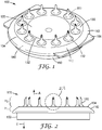
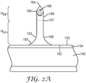
- FIGS. 1-4 show various views of one embodiment of an article 100 according to the present disclosure.
- the article 100 comprises a first side 112 and a second side 114 opposite the first side 112.
- the first side 112 comprises a central cavity portion 120 and a platform portion 130.
- the platform portion 130 projects from the first side 112 and is not coplanar with the central cavity portion 120.
- the central cavity portion 120 and platform portion 130 are both formed as portions of a unitary body 110.
- the central cavity portion 120 and platform portion 130 may be separate parts (not shown) that are disposed adjacent each other in the article.
- the central cavity portion 120 is not coplanar with the platform portion 130. Although the illustrated embodiment of FIGS. 1-4 depict the central cavity portion 120 having a curvilinear surface that slopes away from the plane formed by the platform portion 130, it is contemplated that, in any embodiment, the central cavity portion may comprise one or more angular surfaces (not shown) that are not coplanar with the platform portion.
- the central cavity portion 120 may consist of a solid structure, as shown in FIGS. 1-4 .
- the central cavity portion may comprise, consist essentially of, or consist of an opening (e.g., a through-hole, not shown).
- the platform portion 130 substantially surrounds the central cavity portion 120.
- the platform portion 130 comprises an inner perimeter 132 proximate the central cavity portion 120 and an outer perimeter 134 distal the central cavity portion.
- the inner perimeter 132 and/or outer perimeter 134 comprise a substantially rounded edge, as shown in the side view of the outer perimeter in FIG. 2 and as shown in the cross-sectional view of both perimeters of FIG. 4 .
- the inner perimeter 132 and/or outer perimeter 134 comprise a substantially angular edge (not shown).
- the article 100 further comprises a plurality of hollow microneedles 160 extending from the platform portion 130 in a first direction (see arrow "A", FIG. 2 ).
- the plurality of hollow microneedles 160 can comprise an array.
- the array can comprise a circular arrangement (i.e., a circinate array), as shown in FIG. 3 . It is contemplated that other arrays, having other rectilinear or curvilinear geometric shapes (e.g., a square, a rectangle, an oval, a hexagon; not shown) are also useful in an article according to the present disclosure.
- FIG. 2A shows a detail view of one of the microneedles 160 of the article 100 of FIG. 2 .
- each microneedle 160 of the plurality comprises a body that comprises an outer surface 163, a base segment 166, and a tip segment 168.
- the base segment 166 comprises a base 162 where the microneedle 160 extends from the platform portion 130.
- the base segment 166 has a first shape that is defined by the outer surface 163 of the base segment.
- the first shape is crateriform (i.e., a generally-conical shape with a radius of curvature) and, thus, the diameter of the microneedle is wider at the base 162 than at the tip.
- the base segment 166 has a concave outer surface.
- the tip segment 168 comprises a tip 164.
- the tip 164 is the part of the microneedle 160 that is furthest away from the base 162.
- the tip segment 168 has a second shape that is defined by the outer surface 163 of the microneedle 160. The second shape is distinguishable from the first shape.
- the respective shapes of the base segment 166 and the tip segment 168 become distinguishable at a transition plane 167.
- Transition plane is the plane where an angle formed by a tangent of the outer surface 163 of the microneedle and the central axis changes from a first (tip-proximal) angle of ⁇ 10° to a second (tip-distal) angle of greater than about 10°. In the illustrated embodiment of FIG.
- the outer surface 163 of the microneedle 160 is substantially parallel to the central axis (not shown).
- the substantially straight outer surface of the tip segment 168 i.e. second shape
- the substantially straight outer surface of the tip segment 168 changes to a flared radius of curvature of the base segment 166 (i.e. first shape) and the angle formed by the intersection of a tangent (not shown) of the outer surface and the central axis (not shown) becomes greater than about 10°.
- the substantially cylindrically-shaped tip segment 168 of FIG. 2A is truncated by a bevel 165 that forms a tip 164 that is sharp enough to pierce stratum corneum.
- Each microneedle 160 of the plurality further comprises a hollow channel 169.
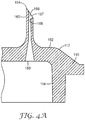
- the hollow channel 169 optionally extends all the way through the article from the first side 112 through the second side 114, as shown in FIG. 4 .
- the hollow channel can provide a dead-end reservoir (e.g., a dead-end reservoir in the body of the microneedle, not shown) in which to load an active ingredient for injection/delivery into the skin, for example.
- a hollow channel 169 extending through the article 100 can be fluidically connected to a reservoir 108 disposed on the second side of the article and an active ingredient can be infused into a patient from the reservoir 108 of the article 100 and through the hollow channel 169 of the microneedle 160.
- the first side 112 optionally comprises a microneedle-free peripheral portion 140 extending laterally from at least a part of the outer perimeter 134 of the platform portion 130.
- the peripheral portion 140 substantially surrounds the platform portion 130.
- the peripheral portion 140 is canted away from the platform portion 130 in a second direction (see arrow "B", FIG. 2 ) opposite the first direction.
- the central cavity portion 120, the platform portion 130, and the peripheral portion 140 are all formed as portions of a unitary body 110.
- the peripheral portion 140 and platform portion 130 may be separate parts (not shown) that are disposed adjacent each other in the article.
- FIG. 4A shows a detail view of one of the sectioned microneedles 160 disposed on the first side 112 of the article the unitary body 110 of FIG. 4 .
- the microneedle 160 comprises a first opening 187 that opens proximate the tip 164 into a hollow channel 169 that extends all the way through the body 110 to a second opening 189 on the second side 112 of the body 110.
- the article 100 further may comprise a tab (e.g., tab 106).
- the tab 106 may be useful for manufacturing purposes or for alignment purposes during use. In the illustrated embodiment, the tab 106 extends laterally from the peripheral portion 140; however other useful configurations will be apparent to a person having ordinary skill in the art.
- the article 100 further comprises a sidewall 150 extending substantially in the direction (i.e., second direction "B" shown in FIG. 2 ) opposite the plurality of microneedles 160.
- the side wall 150 of the illustrated embodiment forms a reservoir 108 on the second side 114 of the article 100.
- the reservoir 108 optionally can be sealed (not shown) and can contain an active agent (e.g., a drug) to be delivered by injection via the plurality of microneedles 160.
- an active agent e.g., a drug
- the article can comprise at least two height dimensions.
- the first height dimension H 1 is the height of the canted peripheral portion 140 extending in the second direction B from the platform portion 130.
- the second height dimension H 2 is the height of each microneedle 160 extending in the first direction A from the platform portion 130.
- each microneedle 160 of the plurality comprises two height components (first height component H 2A and second height component H 2B , respectively) that contribute to the total height of the microneedle 160.
- the first height component represents the height of the base segment 166 of the microneedle 160 and the second height component represents the height of the tip segment 168 of the microneedle.
- the first height component of each microneedle of the plurality according to the present disclosure is about 50 ⁇ m to less than 500 ⁇ m.
- the first height component of each microneedle of the plurality according to the present disclosure is about 150 ⁇ m to about 350 ⁇ m. More preferably, the first height component of each microneedle of the plurality according to the present disclosure is about 200 ⁇ m to about 300 ⁇ m. Even more preferably, the first height component of each microneedle of the plurality according to the present disclosure is about 250 ⁇ m to about 270 ⁇ m.
- the second height component of each microneedle of the plurality according to the present disclosure is about 300 ⁇ m to about 1940 ⁇ m. In any embodiment, the second height component of each microneedle of the plurality according to the present disclosure is about 540 ⁇ m to about 1740 ⁇ m. When the first height component is about 250 ⁇ m to about 270 ⁇ m, preferably, the second height component of each microneedle of the plurality according to the present disclosure is about 540 ⁇ m to about 1240 ⁇ m. When the first height component is about 250 ⁇ m to about 270 ⁇ m, more preferably, the second height component of each microneedle of the plurality according to the present disclosure is about 640 ⁇ m to about 840 ⁇ m. When the first height component is about 250 ⁇ m to about 270 ⁇ m, even more preferably, the second height component of each microneedle of the plurality according to the present disclosure is about 700 ⁇ m to about 800 ⁇ m.
- an article comprising at least three microneedles according to the present disclosure should facilitate penetration of all of the at least three microneedles until at least the tip portion of each microneedle is fully inserted into the skin.
- the tip segment (as measured from the transition plane to the tip of at least one microneedle of the plurality of microneedles) defines at least about 45% of the height of the at least one microneedle. In any embodiment, the tip segment (as measured from the transition plane to the tip of each microneedle of the plurality of microneedles) defines at least about 45% of the height of the microneedles.
- the tip segment (as measured from the transition plane to the tip of at least one microneedle of the plurality of microneedles) defines about 50-95% of the height of the at least one microneedle. In any embodiment, the tip segment (as measured from the transition plane to the tip of each microneedle of the plurality of microneedles) defines about 50-95% of the height of the microneedles. In any embodiment, the tip segment (as measured from the transition plane to the tip of at least one microneedle of the plurality of microneedles) defines about 60-85% of the height of the at least one microneedle.
- the tip segment (as measured from the transition plane to the tip of each microneedle of the plurality of microneedles) defines about 60-85% of the height of the microneedles. In any embodiment, the tip segment (as measured from the transition plane to the tip of at least one microneedle of the plurality of microneedles) defines up to about 70-80% (inclusive) of the height of the at least one microneedle. In any embodiment, the tip segment (as measured from the transition plane to the tip of each microneedle of the plurality of microneedles) defines up to about 70-80% (inclusive) of the height of the microneedles.
- each microneedle 160 of the plurality of microneedles in an article of the present disclosure comprises a central axis 180 as shown in FIGS. 5A, 5B , and 6 .
- the central axis 180 also represents a longitudinal axis of the microneedle 160 extending through the microneedle from the base 162 toward the tip 164.
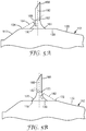
- each microneedle 160 of the plurality may have a spatial relationship between a structural feature (i.e., the microneedle transition plane 167) of the microneedle 160 and one or more of the perimeters (i.e., inner perimeter 132 and outer perimeter 134) of the platform portion 130, as illustrated in FIGS. 5A-B .
- FIG. 5A shows a schematic view of a section of an article comprising a plurality of microneedles according to the present disclosure.
- the article comprises a first side 112 having a central cavity portion 120, a platform portion 130, a canted peripheral portion 140, and an outer perimeter 134 disposed between the platform portion 130 and the peripheral portion 140, as described above. Extending from the platform portion 130 is a microneedle 160.
- the microneedle 160 comprises a base segment 166 with a first shape and a tip segment 168 with a second shape, the segments being separated by a transition plane 167. Also shown in FIG. 5A is the central axis 180 of the microneedle 160 and a shortest line 184 extending from the outer perimeter 134, through the closest point 185 of the transition plane 167 to the outer perimeter 134, to the central axis 180. The intersection of the shortest line 184 with the central axis 180 forms an angle ⁇ 1 . In any embodiment of the article of the present disclosure the angle ⁇ 1 is greater than 50° to about 85°. In any embodiment, the angle ⁇ 1 is about 65° to about 75°.
- the angle ⁇ 1 is less than about 68° to about 72°. In any embodiment, the angle ⁇ 1 is about 70°.
- FIG. 5B shows a similar schematic view of the section of the article shown in FIG. 5A .
- the article comprises a first side 112 having a central cavity portion 120, a platform portion 130, a canted peripheral portion 140, and an inner perimeter 132 disposed between the platform portion 130 and the peripheral portion140, as described above.
- Extending from the platform portion 130 is a microneedle 160.
- the microneedle 160 comprises a base segment 166 with a first shape and a tip segment 168 with a second shape, the segments being separated by a transition plane 167. Also shown in FIG.
- 5B is the central axis 180 of the microneedle 160 and a first shortest line 182 extending from the inner perimeter 132, through the closest point 183 of the transition plane 167 to the inner perimeter 132, to the central axis 180.
- the intersection of the first shortest line 182 with the central axis 180 forms an angle ⁇ 2 .
- the angle ⁇ 2 is greater than 50° to about 85°.
- the angle ⁇ 2 is about 65° to about 75°.
- the angle ⁇ 2 is about 68° to about 72°.
- the angle ⁇ 2 is about 70°.
- FIG. 6 shows a schematic view of a section of an article comprising a plurality of microneedles similar to that shown in FIG. 5A expect the base segment 166 has a first shape that defines a truncated pyramid or truncated cone shape, rather than a crateriform shape.
- the article comprises a first side 112 having a central cavity portion 120, a platform portion 130, a canted peripheral portion 140, and an outer perimeter 134 disposed between the platform portion 130 and the peripheral portion 140, as described above. Extending from the platform portion 130 is a microneedle 160.
- the microneedle 160 comprises a base segment 166 with a first shape and a tip segment 168 with a second shape, the segments being separated by a transition plane 167. Also shown in FIG. 6 is the central axis 180 of the microneedle 160 and a second shortest line 184 extending from the outer perimeter 134, through the closest point 185 of the transition plane 167 to the outer perimeter 134, to the central axis 180. The intersection of the second shortest line 184 with the central axis 180 forms an angle ⁇ 3 . In any embodiment of the article of the present disclosure the angle ⁇ 3 is greater than 50° to about 85°. In any embodiment, the angle ⁇ 3 is about 65° to about 75°.
- the angle ⁇ 3 is about 68° to about 72°. In any embodiment, the angle ⁇ 3 is about 70°.
- the transition plane of at least one microneedle of the plurality is disposed about 60 ⁇ m to about 490 ⁇ m away from the platform portion when measured along the central axis. In any embodiment of an article according to the present disclosure, the transition plane of at least one microneedle of the plurality is disposed about 200 ⁇ m to about 300 ⁇ m away from the platform portion when measured along the central axis. In any embodiment of an article according to the present disclosure, the transition plane of at least one microneedle of the plurality is disposed about 260 ⁇ m away from the platform portion when measured along the central axis.
- the height of at least one microneedle (measured from the base to the tip) of the plurality is about 600 ⁇ m to about 2000 ⁇ m. In any embodiment of an article according to the present disclosure, the height of at least one microneedle (measured from the base to the tip) of the plurality is about 800 ⁇ m to about 1500 ⁇ m. In any embodiment of an article according to the present disclosure, the height of at least one microneedle (measured from the base to the tip) of the plurality is about 900 ⁇ m to about 1100 ⁇ m. In any embodiment of an article according to the present disclosure, the height of at least one microneedle (measured from the base to the tip) of the plurality is about 1000 ⁇ m.
- an article according to the present disclosure comprises a plurality of microneedles wherein the first height component of each microneedle is about 200 ⁇ m to about 300 ⁇ m, the second height component of each microneedle is about 640 ⁇ m to about 840 ⁇ m, the angle ⁇ 1 is about 65-75 degrees, and the angle ⁇ 2 is about 65-75 degrees.
- the article comprises or is operatively coupled to a medicament reservoir and the article is part of an apparatus (e.g., an assembly) wherein the article is operatively coupled to at least one stored energy device that is capable of propelling the microneedles of the article at a velocity (before impact) of about 4 m/sec to about 12 m/sec and capable of urging fluid from the reservoir to and through the hollow microneedles.
- an apparatus e.g., an assembly
- a first stored energy component e.g., a first spring
- a second stored energy component e.g., a second spring
- an article according to the present disclosure comprises a plurality of microneedles wherein the first height component of each microneedle is about 250 ⁇ m to about 270 ⁇ m, the second height component of each microneedle is about 700 ⁇ m to about 800 ⁇ m, the angle ⁇ 1 is about 68-72 degrees, and the angle ⁇ 2 is about 68-72 degrees.
- the article comprises or is operatively coupled to a medicament reservoir and the article is part of an apparatus (e.g., an assembly) wherein the article is operatively coupled to a stored energy device (e.g., an injection and infusion applicator) that is capable of propelling the microneedles of the article at a velocity (before impact) of about 4 m/sec to about 12 m/sec or a velocity (before impact) of about 6 m/sec to about 9 m/sec.
- a stored energy device e.g., an injection and infusion applicator
- articles and assemblies of these preferred embodiments are capable of achieving highly-reproducible depths of penetration of each microneedle to a predefined depth (e.g., about 400 microns to about 800 microns) in skin tissue and delivery of highly-reproducible predefined volumes (e.g., about 0.2 mL to about 3 mL) of medicament within relatively short periods of time (e.g., about1.5 minutes to about 4 minutes.
- a predefined depth e.g., about 400 microns to about 800 microns
- highly-reproducible predefined volumes e.g., about 0.2 mL to about 3 mL
- Arrays of microneedles according to the present disclosure comprise a plurality of spaced-apart microneedles extending from a plane (i.e., the platform portion 130, as shown in FIGS. 1-4 ).
- the configuration of the needles in the arrays improve the penetration and, correspondingly, the delivery of medicament by each needle of the microarray.
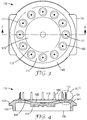
- FIG. 7 shows a top view (i.e., showing the first side 112) of an article 100 comprising a plurality of microneedles 160 according to the present disclosure. In the illustrated embodiment of FIG.
- the article 100 comprises a plurality of microneedles 160 that form an array having a circular (circinate) shape.
- the first side 112 comprises a central cavity portion 120; a platform portion 130, from which the plurality of microneedles 160 extend, surrounding the central cavity portion; and a peripheral portion 140 surrounding the platform portion 130.
- the first side 112 defines a first area A 1 (i.e., a projected area) that includes the central cavity portion 120 and peripheral portion 140 (both shown with a first shading type), the area defined by the base of the microneedles 160 (not shaded), and the platform portion 130 (shown with a second shading type).
- the platform portion 130 defines a second area A 2 within the first area A 1 .
- the second area includes the shaded platform area and the area defined by the base of the microneedles. In any embodiment, the second area A 2 is less than about 40% of the first area A 1 . In any embodiment, the second area A 2 is less than about 35% of the first area A 1 . In any embodiment, the second area A 2 is less than about 30% of the first area A 1 . In any embodiment, the second area A 2 is about 25% to about 40% of the first area A 1 .
- an article of the present disclosure can comprise a reservoir for holding a medicament.
- the reservoir can be in fluidic communication (or selective fluid communication) with each of the hollow microneedles.
- an article according to the present disclosure can be operatively coupled to other components (e.g., a reservoir, a stored energy component) described herein to form an injection and infusion apparatus.
- the injection and infusion apparatus can be used to deliver an injection of medicament into the skin of a subject.
- Such injection and infusion apparatuses are known in the art and include, for example, those described in International Patent Publication No. WO2014/193725 .
- the injection and infusion apparatuses can be actuated to use stored energy (e.g., from springs) to generate motive force that propels the microneedle array articles against skin at a predetermined velocity.
- the injection and infusion apparatus can be configured to propel the microneedle array article at a velocity (before impact with skin) of about 2 m/sec to about 20 m/sec. In any embodiment, the injection and infusion apparatus can be configured to propel the microneedle array article at a velocity (before impact) of about 4 m/sec to about 12 m/sec. In any embodiment, the injection and infusion apparatus can be configured to propel the microneedle array article at a velocity (before impact) of about 6 m/sec to about 9 m/sec. In any embodiment, the injection and infusion apparatus can be configured to propel the microneedle array article at a velocity (before impact) of about 7 m/sec to about 8 m/sec.
- an apparatus comprising a microneedle article according to the present disclosure can be used in a method to insert the microneedles to a predefined depth in skin tissue.
- the depth of penetration of each microneedle in the array can be about 400 ⁇ m to about 850 ⁇ m.
- the average depth of penetration of each microneedle in the array can be about 580 ⁇ m to 750 ⁇ m.
- an apparatus comprising a microneedle article according to the present disclosure can be used in a method to deliver a predefined volume (e.g., about 0.2 mL to about 3 mL) of medicament into skin tissue within a predetermined amount of time.
- the predetermined amount of time can be about 1.5 minutes to about 4 minutes.
- these delivery (i.e., infusion) times are relatively short. These infusion times can be achieved by delivering the medicament at a predetermined rate.
- the medicament infusion rates can be about 0.5 mL/minute to about 1.3 mL/minute.
- Microneedle articles e.g., including articles comprising hollow microneedles
- One embodiment for microneedle array articles includes the structures disclosed in U.S. Patent Application Publication No. 2005/0261631 (Clarke et al. ), which describes microneedles having a truncated tapered shape and a controlled aspect ratio.
- Another embodiment for the microneedle articles includes the structures disclosed in U.S. Patent No. 6,091,975 (Daddona et al. ), which describes blade-like microprotrusions for piercing the skin.
- Still another embodiment for the microneedle articles includes the structures disclosed in U.S. Patent No. 6,312,612 (Sherman et al. ), which describes tapered structures having a hollow central channel. Yet still another embodiment for the microneedle array articles includes the structures disclosed in U.S. Patent No. 6,379,324 (Gartstein et al. ), which describes hollow microneedles having at least one longitudinal blade at the top surface of the tip of the microneedle. A further embodiment for the microneedle array articles includes the structures disclosed in U.S. Patent Application Publication Nos. US2012/0123387(Gonzalez et al. ) and US2011/0213335 (Burton et al. ), which both describe hollow microneedles.
- a still further embodiment for the microneedle array articles includes the structures disclosed in U.S. Patent Nos. 6,558,361 (Yeshurun ) and 7,648,484 (Yeshurun et al. ), which both describe hollow microneedle arrays and methods of manufacturing thereof.
- the microneedle material can be (or include) a metal or a polymeric material, preferably a medical grade polymeric material.
- exemplary types of medical grade polymeric materials include polycarbonate, liquid crystalline polymer (LCP), polyether ether ketone (PEEK), cyclic olefin copolymer (COC), polybutylene terephthalate (PBT).
- Preferred types of medical grade polymeric materials include polycarbonate and LCP.
- microneedle articles of the present disclosure can be manufactured in any suitable way such as by injection molding, compression molding, metal injection molding, stamping, or extrusion.
- hollow microneedle arrays can be made by injection molding of a polymer such as medical grade polycarbonate or LCP, followed by laser drilling to form the channels of the microneedles.
- Nonlimiting examples of molding processes for molding polymeric materials into the solid microneedle articles of the present disclosure can be found in U.S. Patent No. 8,088,321 (Ferguson et al. ) and U.S. Patent Application Publication Nos. 2012/0258284 (Rendon ) and 2012/0041337 (Ferguson et al. ).
- a non-limiting example of a publication that discloses the formation of articles comprising hollow microneedles is PCT Publication No. WO2014/105458 .
- the microneedle material can be (or include) a biodegradable polymeric material, preferably a medical grade biodegradable polymeric material.
- a biodegradable polymeric material preferably a medical grade biodegradable polymeric material.
- exemplary types of medical grade biodegradable materials include polylactic acid (PLA), polyglycolic acid (PGA), PGA and PLA copolymer, polyester-amide polymer (PEA).
- the microneedles can be a prepared from a dissolvable, degradable, or disintegrable material referred to herein as "dissolvable microneedles".
- a dissolvable, degradable, or disintegrable material is any solid material that dissolves, degrades, or disintegrates during use.
- a "dissolvable microneedle” dissolves, degrades, or disintegrates sufficiently in the tissue underlying the stratum corneum to allow a therapeutic agent to be released into the tissue.
- the therapeutic agent may be coated on or incorporated into a dissolvable microneedle.
- the dissolvable material is selected from a carbohydrate or a sugar.
- the dissolvable material is polyvinyl pyrrolidone (PVP).
- PVP polyvinyl pyrrolidone
- the dissolvable material is selected from the group consisting of hyaluronic acid, carboxymethylcellulose, hydroxypropylmethylcellulose, methylcellulose, polyvinyl alcohol, sucrose, glucose, dextran, trehalose, maltodextrin, and a combination thereof.
- the microneedles can be made from (or include) a combination of two or more of any of the above mentioned materials.
- the tip of a microneedle may be a dissolvable material, while the remainder of the microneedle is a medical grade polymeric material.
- a microneedle or the plurality of microneedles in a microneedle-containing article of the present disclosure can have a variety of shapes that are capable of piercing the stratum corneum.
- one or more of the plurality of microneedles can have a segment (e.g., a base segment, a tip segment, or a combination thereof) having a square pyramidal shape, triangular pyramidal shape, stepped pyramidal shape, conical shape, microblade shape, or the shape of a hypodermic needle.
- a segment (e.g., a base segment, a tip segment, or a combination thereof) of one or more of the plurality of microneedles can have a square pyramidal shape.
- a segment (e.g., a base segment, a tip segment, or a combination thereof) of one or more of the plurality of microneedles can have a triangular pyramidal shape.
- a segment (e.g., a base segment, a tip segment, or a combination thereof) of one or more of the plurality of microneedles can have a stepped pyramidal shape.
- a segment (e.g., a base segment, a tip segment, or a combination thereof) of one or more of the plurality of microneedles can have a conical shape.
- a segment (e.g., a base segment, a tip segment, or a combination thereof) of one or more of the plurality of microneedles can have a microblade shape.
- a segment (e.g., a base segment, a tip segment, or a combination thereof) of one or more of the plurality of microneedles can have the shape of a hypodermic needle.
- a microneedle array article may comprise an array of microneedles having a combination of any two or more of the foregoing microneedle shapes. The shape of any microneedle in the microneedle array article can be symmetric or asymmetric.
- any microneedle in the microneedle array article can be truncated (for example, the plurality of microneedles can have a truncated pyramid shape or truncated cone shape).
- each microneedle of the plurality of microneedles in a microneedle array article has a square pyramidal shape.
- each microneedle of the plurality of microneedles in a microneedle article is solid microneedles (that is, the microneedles do not comprise a through-hole).
- each microneedle of the plurality of solid microneedles in a solid microneedle array article can have a segment (e.g., a base segment, a tip segment, or a combination thereof) with a square pyramidal shape, triangular pyramidal shape, stepped pyramidal shape, conical shape, or microblade shape.
- each microneedle of the plurality of solid microneedles in a solid microneedle array article has a segment (e.g., a base segment, a tip segment, or a combination thereof) with a square pyramidal shape or a conical shape with a radius of curvature.
- each microneedle of the plurality of microneedles in a microneedle array is a hollow microneedle (that is, the microneedle contains a hollow bore through the microneedle).
- the hollow bore can be from the base of the microneedle to the tip of the microneedle or the bore can be from the base of the microneedle to a position offset from the tip of the microneedle.
- one or more of the plurality of hollow microneedles in a hollow microneedle array can have a conical shape, cylindrical shape, square pyramidal shape, triangular pyramidal shape, or the shape of a hypodermic needle.
- one or more microneedle of the plurality of hollow microneedles in a hollow microneedle array article can have a conical shape; optionally, with a radius of curvature. In any embodiment, one or more microneedle of the plurality of hollow microneedles in a hollow microneedle array article can have a cylindrical shape. In any embodiment, one or more microneedle of the plurality of hollow microneedles in a hollow microneedle array article can have a segment (e.g., a base segment, a tip segment, or a combination thereof) having a square pyramidal shape.
- one or more microneedle of the plurality of hollow microneedles in a hollow microneedle array article can have a segment (e.g., a base segment, a tip segment, or a combination thereof) having a triangular pyramidal shape.
- one or more microneedle of the plurality of hollow microneedles in a hollow microneedle array article can have a segment (e.g., a base segment, a tip segment, or a combination thereof) having the shape of a hypodermic needle.
- each microneedle of the plurality of hollow microneedles in a hollow microneedle array article has a segment (e.g., a base segment, a tip segment, or a combination thereof) with the shape of a conventional hypodermic needle.
- an article comprising a hollow microneedle according to the present disclosure may comprise a plurality of the microneedles.
- the plurality of the microneedles optionally may form an array.
- the article can comprise an array of about 3 to about 30, inclusive, of the hollow microneedles of the present disclosure.
- the article can comprise an array of about 8 to about 20, inclusive, of the hollow microneedles of the present disclosure.
- the article can comprise an array of 12, 16, or 18 of the hollow microneedles of the present disclosure.
- the overall height of each microneedle is about 600 ⁇ m to about 2000 ⁇ m. In any embodiment of an article comprising a plurality of hollow microneedles according to the present disclosure, the overall height of each microneedle is about 700 ⁇ m to about 1500 ⁇ m. In any embodiment of an article comprising a plurality of hollow microneedles according to the present disclosure, the overall height of each microneedle is about 900 ⁇ m to about 1100 ⁇ m.
- a hollow channel extending through each of the microneedles has a diameter, proximate the tip of the microneedle, of about 10 ⁇ m to about 200 ⁇ m. In any embodiment of an article comprising a plurality of hollow microneedles according to the present disclosure, a hollow channel extending through each of the microneedles has a diameter, proximate the tip of the microneedle, of about 10 ⁇ m to about 120 ⁇ m.
- a hollow channel extending through each of the microneedles has a diameter, proximate the tip of the microneedle, of about 25 ⁇ m to about 75 ⁇ m.
- a hollow channel extending through each of the microneedles has a cross-sectional area of about 75 ⁇ m 2 to about 32,000 ⁇ m 2 . In any embodiment of an article comprising a plurality of hollow microneedles according to the present disclosure, a hollow channel extending through each of the microneedles has a cross-sectional area of about 75 ⁇ m 2 to about 18,000 ⁇ m 2 . In any embodiment of an article comprising a plurality of hollow microneedles according to the present disclosure, a hollow channel extending through each of the microneedles has a cross-sectional area of about 700 ⁇ m 2 to about 3,000 ⁇ m 2 .
- microneedle array articles of the present disclosure can be manufactured by injection molding of a polymer such as medical grade polycarbonate or LCP. Typically, these processes use molds to form the substrate with the microneedles extending therefrom.
- a polymer such as medical grade polycarbonate or LCP.
- At least one hollow microneedle in an article according to the present disclosure can have a tip segment that has any shape or structure that facilitates, or does not interfere with, the ability of the microneedle to penetrate the surface of skin.
- the tip segment may comprise an opening (e.g., either a depression, dead-end cavity, or a through-hole that extends all the way through the microneedle) that facilitates the delivery of (and, optionally, storage therein) an active compound.
- at least one hollow microneedle of the plurality of microneedles comprises a base, an elongated body having a central axis and a body diameter, and a tip segment with two bevel faces.
- the tip segment comprises a tip, a first bevel face oriented diagonally with respect to the central axis and extending through at least 75% of the body diameter, a second bevel face oriented substantially perpendicular to the central axis and intersecting the first bevel face, a bevel opening defined by a first edge of the first bevel face and a second edge of the second bevel face.
- a microneedle tip with two bevel faces is described in PCT Publication No. WO2015/009524 .
- At least one hollow microneedle in an article according to the present disclosure can have a tip segment that comprises an opening that is formed by two channels that merge to form the opening.
- the at least one microneedle comprises a base, an elongated body having a central axis, a tip segment with a beveled surface and a bevel opening in the bevel surface, a first channel that extends axially from the bevel opening through at least a portion of the elongated body, and a second channel that extends radially from the first channel to the bevel opening.
- the first channel has a first wall that is substantially aligned with the central axis.
- the second channel has a second wall that is oriented substantially orthogonal to the central axis.
- the first channel and second channel merge to form the bevel opening.
- a microneedle tip that comprises an opening that is formed by two channels that merge to form the opening, is described in PCT Publication No. WO2015/009523
- articles of the present disclosure can be used with an injection and infusion apparatus (e.g., a single-use applicator or a reusable applicator) that is configured to urge the plurality of microneedles of the article against a skin surface.
- actuation of the injection and infusion apparatus can occur through single actuation or through dual actuation.
- a non-limiting example of a single-actuation injection and infusion apparatus is disclosed in US Patent Application Publication No. 2012/0123387 (Gonzalez et al. ).
- the use of microneedle articles with a dual-actuation or dual automatic actuation is described, for example, in PCT Publication No. WO2014/099404 .
- an article of the present disclosure can be used with an injection and infusion apparatus comprising an adhesive assembly such as, for example, the injection and infusion apparatus comprising the adhesive assembly described in PCT Publication No. WO2014/099404 .
- the adhesive assembly can comprise a skin-contact adhesive layer such as, for example, the injection and infusion apparatus comprising the skin-contact adhesive layer described in PCT Publication No. WO2014/099404 .
- the skin-contact adhesive layer can comprise an annular configuration that, in use, surrounds the microneedle article of the present disclosure and, optionally, secures the article to a skin surface while an active compound (e.g., an active compound that is part of a pharmaceutical composition) is delivered from (or through) the microneedle into a patient.
- an active compound e.g., an active compound that is part of a pharmaceutical composition
- FIG. 8 shows a plan view of a portion of the skin-facing surface of one embodiment of an injection and infusion apparatus configured for use with an article comprising a plurality of hollow microneedles according to the present disclosure.
- the injection and infusion apparatus 400 comprises a skin-contact adhesive layer 490 that substantially surrounds the article 100.
- the article comprises a first side 112 that comprises a central cavity portion 120 surrounded by a platform portion 130 that is not coplanar with the central cavity portion 120 (i.e., the platform is raised above the central cavity).
- a circinate array of spaced-apart microneedles 160 extend from the first side of the platform portion 130.
- the first side 112 further comprises an optional peripheral portion 140 that surrounds the platform portion 130 and that is not coplanar with the platform portion (i.e., the platform is raised above the peripheral portion).
- the article 100 is attached (e.g., detachably attached) to the injection and infusion apparatus 400 using various attachment means (e.g., an adhesive, a clamp, friction fit, and the like, not shown).
- the platform portion 130 is a ring-shaped (i.e., circinate) platform that surrounds the central cavity portion.
- Dimension D1 represents the diameter of the central cavity portion 120, as defined by the inner perimeter 132 of the platform portion 130.
- Dimension D2 represents the outer diameter of the platform portion 130, as defined by the outer perimeter 134 of the platform portion.
- Dimension D3 represents the outer diameter of the ring-shaped peripheral portion 140 that surrounds the platform portion 130.
- Dimension D4 represents the width of the platform portion, as measured along a radius (not shown) extending from the center of the circular-shaped article.
- D5 represents the shortest distance, as measured along a radius (not shown) extending from the center of the circular-shaped article, between the tip of a microneedle 160 and the skin-contact layer adhesive 490 of the injection and infusion apparatus 400.
- the shape of the skin-contact adhesive layer is shaped and dimensioned so that the shortest distance between each microneedle tip in the array is and the skin-contact adhesive layer 490 approximately equal (e.g., less than about 10% variability).
- the microneedle articles were prepared from polymeric material using standard injection molding procedures.
- the molded microneedle articles were prepared using a mold assembly prepared from three mold sections with each section machined from steel.
- the first mold section contained projections that defined the beveled shape of the needle tip in the molded array.
- Each projection in the first mold section had a further cylindrical extension that defined features of the tip segment of the microneedles tip, including the opening on a bevel proximate the tip of the microneedle and a portion of the hollow channel extending through the body of each microneedle.
- the second mold section served as a template to define the pattern of the microneedles in the molded article, the external shape and size of the microneedles in the molded article, and the first side of the article (including the central cavity portion, platform portion, and peripheral portion, as described above).
- the third mold section contained cylindrical projections emerging from a planar surface with each projection defining a second (base-proximal) part of the microneedle hollow channel and the opening located at the base of each microneedle in the molded article.
- the planar surface from which the projections emerged served to define the second major surface of the base segment of the molded article.
- the first and second mold sections were assembled to form a tight fit by inserting the projections of the first mold section into the corresponding openings in the second mold section.
- the assembled first and second mold sections formed the first mold half.
- the third mold section was used as the second mold half.
- the first and second mold halves were installed in a mold base in a 20 or 40-ton injection molding press.
- the parting line of the mold assembly had both primary and secondary vents for general air evacuation during injection of the polymeric material.
- Vectra MT1300 liquid crystal polymer (LCP) pellets (Ticona Engineering Polymers, Florence, KY) were loaded into a screw and heated until molten.
- the first mold half and second mold half were heated to a temperature range (hereafter referred to as the "mold temperature at injection") of about 140-248 °F (60-120° C).
- the molding cycle was initiated by closing the first mold half with the second mold half.
- the molds were clamped together with approximately 20 to 40 tons of force.
- the surfaces at the tips of the projections in the second mold half were aligned with and in contact with the surfaces at the tips of the projections in the first mold half.
- a first portion (approx. 50-99% of the part size volume) of the total amount of material was injected into the mold chamber at a fixed velocity (hereafter referred to as the "injection velocity") of about 7 inches/second (17.8 cm/second).
- the process was switched from an injection-driven to a pressure-driven mode by applying a fixed pressure (hereafter referred to as the "pack pressure") ranging from about 3,000-13,500 psi (20,684-93,079 kilopascal) to force the remainder of the molten material into the negative mold insert.
- the pack pressure was applied for a fixed time (hereafter referred to as the "hold time") of 2-6 seconds.
- the pack pressure was subsequently released and the mold chamber was cooled to an ejection temperature set below the softening temperature of LCP.
- the mold chamber was opened and the microneedle article was ejected.
- Example 2 Injection applicator used to test the microneedle articles.
- the glass cartridge in each injection and infusion apparatus contained a 2 mL solution of 0.005% methylene blue in five percent aqueous dextrose. Each cartridge was about 46 mm in length and had an inner diameter dimension of about 9.7 mm.
- the first stored energy device used to move the microneedle array holder and insert the microneedles in the skin was a coil spring with a force of 12.5 N in the primed (pre-actuation) state.
- the second stored energy device used to initiate movement of the shuttle was a coil spring with a force of 16.5 N in the primed (pre-actuation) state.
- the third stored energy device used to infuse the methylene blue dye was a coil spring with a force of 15 N in the primed (pre-actuation) state.
- the velocity of the microneedles at the surface of the skin was about 7.4 ⁇ 1.4 m/sec.
- the hollow microneedle article (as shown in FIG. 1 ) used in the microneedle article injection and infusion apparatus was molded (as described in Example 1) from Vectra MT1300 liquid crystal polymer (LCP) in the shape of a circle approximately 1.25 cm in diameter (dimension D3 of FIG. 8 ).
- the circular platform portion projected about 1.0 mm from the outside edge of the article (Height H 1 of FIG. 2 ) and the peripheral portion canted away from the platform portion with a 36.9 degree cant, relative to the plane of the platform portion.
- the closed circular cavity of the article was centered on the article with a diameter of about 6.8 mm (diameter measurement D1 ( FIG.
- the article featured an array of 12 hollow microneedles extending from the circular platform portion of the article. The microneedles were evenly spaced with the distance between neighboring microneedles being about 2.2 mm
- each microneedle was oriented so that the opening at the tip was facing toward the outer perimeter of the article along a radial vector.
- the external diameter of each microneedle at the base was about 0.45 mm.
- the flared base segment of each microneedle had a radius of curvature of about 1 mm.
- the tip segment of each microneedle was in the shape of a conventional hypodermic needle with a bevel of about 25 degrees and a chamfered tip that had an included angle of 70 degrees.
- the opening near the tip was obround in shape (as shown in FIG. 2A ) with dimensions of about 200 microns by 80 microns.
- Each microneedle had a total height of about 1000 microns as measured from the base of the microneedle at the platform surface to the tip of the microneedle.
- the length of the tip segment (as measured from the tip to the transition plane that delineated the flared base segment from the substantially cylindrical tip segment, FIG. 2A ) was about 739 microns.
- the external diameter at the midpoint of the tip segment was about 254 microns.
- the distance from the tip of each microneedle to the center of the opening near the tip was about 270 microns.
- the average diameter of the hollow channel through the tip segment of each microneedle was about 80 microns.
- the angle theta ( ⁇ 1 , as shown in FIG. 5A ) was 70.0 degrees.
- Example 3 Use of microneedle article to inject a substance.
- the ham region was selected as the application site for microneedle insertion.
- the application site was first trimmed with an electric clipper and then shaved using a razor and shaving cream.
- the shaved area was scrubbed using soapy water and a BUF-PUF exfoliation sponge (3M Company, St. Paul, MN) and then rinsed with deionized water.
- the animal was anesthetized with isofluorene gas and maintained under anesthesia throughout the experiment.
- the application site was then wiped with a 70% isopropanol in water solution.
- Example 2 The injection apparatus of Example 2 was used. The release liner was removed from the skin contact adhesive portion of the apparatus was adhered to the skin of the pig. The apparatus was actuated to cause sequential release of the array holder element, insertion of the microneedles of the microneedle article into the skin of the pig, and injection of the methylene blue solution into the pig. After completion of the injection, the apparatus was maintained on the skin for one additional minute. The time required to inject the entire sample into the animal was recorded. The apparatus was removed from the skin and the skin surface was examined to determine if there was any methylene blue solution on the surface of the skin. The presence of methylene blue solution on the skin was an indication that not all of the methylene blue was injected into the animal. The remainder of the methylene blue solution remained in the cartridge. The results are presented in Table 1.
- Example 4 Use of microneedle article.
- DOP depth of penetration
- the microneedles on the article were coated using a three step process.
- the first two steps involved applying primer coatings to the microneedles and the third step involved applying a thin coating of Rhodamine B to the microneedles.
- Step 1 the articles were flood coated with a 35 microliter solution containing 0.5 mg/mL polyvinyl alcohol (80% hydrolyzed) (Sigma-Aldrich, Inc., St. Louis, MO) and 35 ⁇ g/ml of TWEEN® 80 (Sigma-Aldrich) in 90% (w/v) ethanol. The coated articles were then dried at 35° C for 20 minutes.
- polyvinyl alcohol 80% hydrolyzed
- TWEEN® 80 Sigma-Aldrich
- Step 2 the articles from Step 1 were flood coated with 35 microliters of an aqueous solution of 33.3 mg/ml aluminum potassium sulfate (Penta Manufacturing, Livingston, NJ). The coated articles were then dried at 35 °C for 30 minutes.
- Step 3 the primed articles from Step 2 were flood coated with 40 microliters of an aqueous solution of 0.08% (w/v) Rhodamine B (Sigma-Aldrich). The coated articles were dried at 35° C for 30 minutes.
- the three step process provided articles in which the microneedles were completely covered with a thin, opaque coating of Rhodamine B.
- the ham region was selected as the application site for microneedle insertion.
- the application site was first trimmed with an electric clipper and then shaved using a razor and shaving cream.
- the shaved area was scrubbed using soapy water and a BUF-PUF exfoliation sponge (3M Company) and then rinsed with deionized water.
- the animal was placed in a lateral recumbent position on a heated table (38° C).
- the animal was anesthetized with isofluorene gas and maintained under anesthesia throughout the experiment.
- the application site was then wiped with a 70% isopropanol in water solution.
- Example 2 The injection apparatus described in Example 2 with a Rhodamine B coated article was used. The only exception was that a blank cartridge was used, instead of a cartridge filled with methylene blue.
- the release liner was removed from the skin contact adhesive portion of the apparatus and the apparatus was the adhered to the skin of the pig.
- the apparatus was actuated to cause release of the array holder element and insertion of the microneedles of the microneedle article into the skin of the pig.
- the injection apparatus was maintained on the skin for an additional 5 minutes.
- the injection apparatus was removed from the animal.
Landscapes
- Health & Medical Sciences (AREA)
- Life Sciences & Earth Sciences (AREA)
- Engineering & Computer Science (AREA)
- General Health & Medical Sciences (AREA)
- Veterinary Medicine (AREA)
- Biomedical Technology (AREA)
- Heart & Thoracic Surgery (AREA)
- Public Health (AREA)
- Medical Informatics (AREA)
- Animal Behavior & Ethology (AREA)
- Hematology (AREA)
- Physics & Mathematics (AREA)
- Biophysics (AREA)
- Pathology (AREA)
- Molecular Biology (AREA)
- Surgery (AREA)
- Dermatology (AREA)
- Anesthesiology (AREA)
- Optics & Photonics (AREA)
- Media Introduction/Drainage Providing Device (AREA)
- Infusion, Injection, And Reservoir Apparatuses (AREA)
Description
- This application claims priority to
U.S. Provisional Patent Application No. 62/105,987, filed January 21, 2015 - Transdermal and topical drug delivery can be used for therapeutic treatment, but the number of molecules that can be effectively delivered using these routes can be limited by the barrier properties of skin. The main barrier to transport of molecules through the skin is the stratum corneum (the outermost layer of the skin).
- A number of different skin treatment methods have been proposed in order to increase the permeability or porosity of the outermost skin layers, such as the stratum corneum, thus enhancing drug delivery through or into those layers. The stratum corneum is a complex structure of compact keratinized cell remnants separated by lipid domains. The stratum corneum is formed of keratinocytes, which comprise the majority of epidermal cells that lose their nuclei and become corneocytes. These dead cells comprise the stratum corneum, which has a thickness of only about 10-30 microns and protects the body from invasion by exogenous substances and the outward migration of endogenous fluids and dissolved molecules. Various skin treatment methods include the use of microneedles, laser ablation, RF ablation, heat ablation, sonophoresis, iontophoresis, or a combination thereof.
- Devices including arrays of relatively small structures, sometimes referred to as microneedles or micro-pins, have been disclosed for use in connection with the delivery of therapeutic agents and other substances through the skin and other surfaces. The devices are typically pressed against the skin in an effort to pierce the stratum corneum such that the therapeutic agents and other substances can sequentially or simultaneously pass through that layer and into the tissues below. Microneedles of these devices pierce the stratum corneum upon contact, making a plurality of microscopic slits which serve as passageways through which molecules of active components can be delivered into the body. In delivering an active component, the microneedle device can be provided with a reservoir for temporarily retaining an active component in liquid form prior to delivering the active component through the stratum corneum. In some constructions, the microneedles can be hollow to provide a liquid flow path directly from the reservoir and through the microneedles to enable delivery of the therapeutic substance through the skin. In alternate constructions, active component(s) may be coated on the microneedle array and delivered directly through the skin after the stratum corneum has been punctured.
- Microneedle arrays can be used in conjunction with an injection and infusion apparatus (i.e., an "applicator" that applies the hollow microneedles to the skin and facilitates infusion of a substance through the hollow microneedles) capable of being used several times or as a single-use device. The microneedle arrays are generally used once and then discarded.
-
US 2011/0172609 A1 discloses a device for delivering a drug to a subject. The device includes a drug reservoir, a conduit coupled to the drug reservoir and a microneedle component. The microneedle component includes a body, an engagement structure coupling the microneedle component to the conduit, a hollow microneedle extending from the body, and a handling feature located on the body. -
DE 10 2008 052 749 A1 discloses a needle having a piercing end comprising a shape of an obliquely truncated cylinder or frustum. -
US 2011/0046556 A1 discloses a device for local anesthesia injection. The device comprises a cone with a base on the bottom and a chamber and a flange on the top, having a delivery device connect to the flange, with a plurality of conduits that run from the chamber to a plurality of needles that extend out from the base and having a foam ring attached to the base covering the needles. - An article as recited in the independent claim is provided. The dependent claims define embodiments.
- It has now been found that an interaction between an article comprising a plurality of hollow microneedles and a skin surface against which the article is urged can result in undesirable effects on the penetration of at least one microneedle of the plurality into the skin. It has further been found that, when the article comprises an array of microneedles, one of the effects can be significant variability in the depth of penetration into the skin by one or more of the microneedles in the array. The present inventors recognized the consistency of penetration depth can be controlled by including several features into the design of the article. The inventive design features result in the ability to rapidly, effectively and consistently insert the needles to a desired depth in the skin and quickly deliver a pharmaceutically-effective dose in a variety of skin locations. In addition, certain features of the inventive design permit simpler, more robust processes to be used for the manufacture of the articles.
- The present disclosure generally relates to articles comprising microneedles and their use to deliver materials through the surface of skin or remove biological fluids through the surface of skin. In particular, the present disclosure relates to an article comprising an array of a plurality of microneedles that is configured to provide consistent depths of penetration for each microneedle of the plurality of microneedles by facilitating the contact between microneedles and skin and by reducing the possibility of contact between skin and non-microneedle surfaces during the use of the articles.
- Some aspects of the present disclosure provide an article. The article can comprise a first side, a second side opposite the first side, and at least three hollow microneedles. The first side can comprise a central cavity portion and a platform portion that projects from the first side and that is not coplanar with the central cavity portion. The microneedles can extend from the platform portion in a first direction. The platform portion can substantially surround the central cavity portion and can comprise an inner perimeter proximate the central cavity portion and an outer perimeter distal the central cavity portion. Each of the at least three microneedles comprises a body that comprises an outer surface; a base segment having a base and a first shape that is defined by a first section of the outer surface; a tip segment having a tip and a second shape that is defined by a second section of the outer surface, wherein the second shape is distinct from the first shape; a transition plane that delineates the base segment and the tip segment; and a central axis. A first angle, defined by the central axis of each of the at least three microneedles and a shortest line extending from the outer perimeter of the platform and through the transition plane of the at least one microneedle, is greater than 50° and less than or equal to about 85°. In any embodiment, the first angle can be about 65° to about 75°, inclusive. In any of the above embodiments, the first angle can be about 70°.
- Other aspects of the present disclosure provide an article. The article can comprise a first side, a second side opposite the first side, and at least three hollow microneedles. The first side can comprise a central cavity portion and a platform portion that projects from the first side and that is not coplanar with the central cavity portion. The microneedles can extend from the platform portion in a first direction. The platform portion can substantially surround the central cavity portion and can comprise an inner perimeter proximate the central cavity portion and an outer perimeter distal the central cavity portion. Each of the at least three microneedles comprises a body that comprises an outer surface; a base segment having a base and a first shape that is defined by a first section of the outer surface; a tip segment having a tip and a second shape that is defined by a second section of the outer surface, wherein the second shape is distinct from the first shape; a transition plane that delineates the base segment and the tip segment; and a central axis. Each of the at least three microneedles comprises a height measured from the base to the tip. The tip segment of each of the at least three microneedles can define at least about 45% of the height of the microneedle. In any embodiment, the tip segment of each of the at least three microneedles can define at least about 70-80% of the height of the microneedle.
- The phrase "injection apparatus" refers to an integrated device capable of delivering or extracting a fluid over a certain period and is not limited to devices intended solely for an infusion. Accordingly, an injection apparatus may be used, for example, for injecting fluid into the dermis or extracting fluid from tissue.
- The term "transdermally" and variations thereof, is generally used to refer to any type of delivery of an active ingredient that crosses any portion of skin. That is, transdermally can generally include systemic delivery (i.e., where the active ingredient is transported across, or substantially through, the dermis such that the active ingredient is delivered into the bloodstream), as well as intradermal delivery (i.e., where the active ingredient is transported partially through the dermis, e.g., across the outer layer (stratum corneum) of the skin, where the active ingredient is delivered into the skin, e.g., for treating psoriasis or for local anesthetic delivery). That is, transdermal delivery as used herein includes delivery of an active ingredient that is transported across at least a portion of skin (but not necessarily all of the layers of skin), rather than merely being topically applied to an outer layer of the skin.
- The phrase "hollow microneedle" refers to a specific microscopic structure that is designed for piercing the stratum corneum to facilitate the delivery of drugs through the skin. By way of example, microneedles can include needle or needle-like structures, as well as other structures capable of piercing the stratum corneum and delivering liquid drug formulations to skin or tissue layers beneath the stratum corneum.
- The words "preferred" and "preferably" refer to embodiments of the invention that may afford certain benefits, under certain circumstances. However, other embodiments may also be preferred, under the same or other circumstances. Furthermore, the recitation of one or more preferred embodiments does not imply that other embodiments are not useful, and is not intended to exclude other embodiments from the scope of the invention.
- The terms "comprises" and variations thereof do not have a limiting meaning where these terms appear in the description and claims.
- As used herein, "a," "an," "the," "at least one," and "one or more" are used interchangeably. Thus, for example, a microneedle can be interpreted to mean "one or more" microneedles.
- The term "and/or" means one or all of the listed elements or a combination of any two or more of the listed elements.
- Also herein, the recitations of numerical ranges by endpoints include all numbers subsumed within that range (e.g., 1 to 5 includes 1, 1.5, 2, 2.75, 3, 3.80, 4, 5, etc.).
- The above summary of the present invention is not intended to describe each disclosed embodiment or every implementation of the present invention. The description that follows more particularly exemplifies illustrative embodiments. In several places throughout the application, guidance is provided through lists of examples, which examples can be used in various combinations. In each instance, the recited list serves only as a representative group and should not be interpreted as an exclusive list.
- Additional details of these and other embodiments are set forth in the accompanying drawings and the description below. Other features, objects and advantages will become apparent from the description and drawings, and from the claims.
- The present invention will be further explained with reference to the drawing figures listed below, where like structure is referenced by like numerals throughout the several views.
-
FIG. 1 is a perspective view showing one embodiment of an article comprising a plurality of microneedles according to the present disclosure. -
FIG. 2 is a side view of the article ofFIG. 1 . -
FIG. 2A is a detail view of a portion of the article ofFIG. 2 . -
FIG. 3 is a plan view of the first side of the article ofFIG. 1 . -
FIG. 4 is a cross-sectional view, taken along line 4-4, of the article ofFIG. 3 . -
FIG. 4A is a detailed cross-sectional view of one of the hollow microneedles ofFIG. 4 . -
FIG. 5A is a schematic side view, partially in section, of a portion of the article ofFIG. 1 , showing an angle θ1 formed by the intersection of a central axis of a microneedle with a line passing through a transition plane in the microneedle. -
FIG. 5B is a schematic side view, partially in section, of the article ofFIG. 5A , showing an angle θ2 formed by the intersection of a central axis of a microneedle with a line passing through a transition plane in the microneedle. -
FIG. 6 is a schematic side view, partially in section, of a portion of another embodiment of an article comprising a microneedle, showing an angle θ3 formed by the intersection of a central axis of a microneedle with a line passing through a transition plane in the microneedle. -
FIG. 7 is a plan view of an article according to the present disclosure; showing areas defined on the first side of the article. -
FIG. 8 is a plan view of a portion of an injection and infusion applicator coupled to an article comprising a plurality of microneedles according to the present disclosure; showing various dimensions associated with the article and the injection and infusion applicator. - Before any embodiments of the present disclosure are explained in detail, it is to be understood that the invention is not limited in its application to the details of construction and the arrangement of components set forth in the following description or illustrated in the following drawings. The invention is capable of other embodiments and of being practiced or of being carried out in various ways. Also, it is to be understood that the phraseology and terminology used herein is for the purpose of description and should not be regarded as limiting. The use of "including," "comprising," or "having" and variations thereof herein is meant to encompass the items listed thereafter and equivalents thereof as well as additional items. Unless specified or limited otherwise, the terms "mounted," "connected," "supported," and "coupled" and variations thereof are used broadly and encompass both direct and indirect mountings, connections, supports, and couplings. It is to be understood that other embodiments may be utilized, and structural or logical changes may be made without departing from the scope of the present disclosure. Furthermore, terms such as "front," "rear," "top," "bottom," and the like are only used to describe elements as they relate to one another, but are in no way meant to recite specific orientations of the apparatus, to indicate or imply necessary or required orientations of the apparatus, or to specify how the invention described herein will be used, mounted, displayed, or positioned in use.
- The present disclosure generally relates to articles comprising microneedles and their use to deliver materials through the surface of skin or remove biological fluids through the surface of skin. In particular, the present disclosure relates to an article comprising an array of a plurality of microneedles that is configured to provide consistent depths of penetration for each microneedle of the plurality of microneedles by facilitating the contact between microneedles and skin and by reducing the possibility of contact between skin and non-microneedle surfaces during the use of the articles.
- Turning to the drawings,
FIGS. 1-4 show various views of one embodiment of anarticle 100 according to the present disclosure. Thearticle 100 comprises afirst side 112 and asecond side 114 opposite thefirst side 112. Thefirst side 112 comprises acentral cavity portion 120 and aplatform portion 130. Theplatform portion 130 projects from thefirst side 112 and is not coplanar with thecentral cavity portion 120. In the illustrated embodiment ofFIGS. 1-4 , thecentral cavity portion 120 andplatform portion 130 are both formed as portions of aunitary body 110. However, in any embodiment, it is contemplated that thecentral cavity portion 120 andplatform portion 130 may be separate parts (not shown) that are disposed adjacent each other in the article. - The
central cavity portion 120 is not coplanar with theplatform portion 130. Although the illustrated embodiment ofFIGS. 1-4 depict thecentral cavity portion 120 having a curvilinear surface that slopes away from the plane formed by theplatform portion 130, it is contemplated that, in any embodiment, the central cavity portion may comprise one or more angular surfaces (not shown) that are not coplanar with the platform portion. - In any embodiment, the
central cavity portion 120 may consist of a solid structure, as shown inFIGS. 1-4 . Alternatively, in any embodiment, the central cavity portion may comprise, consist essentially of, or consist of an opening (e.g., a through-hole, not shown). - The
platform portion 130 substantially surrounds thecentral cavity portion 120. Theplatform portion 130 comprises aninner perimeter 132 proximate thecentral cavity portion 120 and anouter perimeter 134 distal the central cavity portion. In any embodiment, theinner perimeter 132 and/orouter perimeter 134 comprise a substantially rounded edge, as shown in the side view of the outer perimeter inFIG. 2 and as shown in the cross-sectional view of both perimeters ofFIG. 4 . Alternatively, in any embodiment, theinner perimeter 132 and/orouter perimeter 134 comprise a substantially angular edge (not shown). - The
article 100 further comprises a plurality ofhollow microneedles 160 extending from theplatform portion 130 in a first direction (see arrow "A",FIG. 2 ). In any embodiment, the plurality ofhollow microneedles 160 can comprise an array. The array can comprise a circular arrangement (i.e., a circinate array), as shown inFIG. 3 . It is contemplated that other arrays, having other rectilinear or curvilinear geometric shapes (e.g., a square, a rectangle, an oval, a hexagon; not shown) are also useful in an article according to the present disclosure. -
FIG. 2A shows a detail view of one of themicroneedles 160 of thearticle 100 ofFIG. 2 . In any embodiment of thearticle 100, eachmicroneedle 160 of the plurality comprises a body that comprises anouter surface 163, abase segment 166, and atip segment 168. Thebase segment 166 comprises a base 162 where themicroneedle 160 extends from theplatform portion 130. Thebase segment 166 has a first shape that is defined by theouter surface 163 of the base segment. In the illustrated embodiment ofFIG. 2A , the first shape is crateriform (i.e., a generally-conical shape with a radius of curvature) and, thus, the diameter of the microneedle is wider at the base 162 than at the tip. Optionally, thebase segment 166 has a concave outer surface. - The
tip segment 168 comprises atip 164. Thetip 164 is the part of themicroneedle 160 that is furthest away from thebase 162. Thetip segment 168 has a second shape that is defined by theouter surface 163 of themicroneedle 160. The second shape is distinguishable from the first shape. The respective shapes of thebase segment 166 and thetip segment 168 become distinguishable at atransition plane 167. "Transition plane", as used herein is the plane where an angle formed by a tangent of theouter surface 163 of the microneedle and the central axis changes from a first (tip-proximal) angle of ≤10° to a second (tip-distal) angle of greater than about 10°. In the illustrated embodiment ofFIG. 3A , theouter surface 163 of themicroneedle 160 is substantially parallel to the central axis (not shown). However, at thetransition plane 167, the substantially straight outer surface of the tip segment 168 (i.e. second shape) changes to a flared radius of curvature of the base segment 166 (i.e. first shape) and the angle formed by the intersection of a tangent (not shown) of the outer surface and the central axis (not shown) becomes greater than about 10°. The substantially cylindrically-shapedtip segment 168 ofFIG. 2A is truncated by abevel 165 that forms atip 164 that is sharp enough to pierce stratum corneum. - Each
microneedle 160 of the plurality further comprises ahollow channel 169. Thehollow channel 169 optionally extends all the way through the article from thefirst side 112 through thesecond side 114, as shown inFIG. 4 . In any embodiment, the hollow channel can provide a dead-end reservoir (e.g., a dead-end reservoir in the body of the microneedle, not shown) in which to load an active ingredient for injection/delivery into the skin, for example. In any embodiment, ahollow channel 169 extending through thearticle 100 can be fluidically connected to areservoir 108 disposed on the second side of the article and an active ingredient can be infused into a patient from thereservoir 108 of thearticle 100 and through thehollow channel 169 of themicroneedle 160. - In any embodiment, the
first side 112 optionally comprises a microneedle-freeperipheral portion 140 extending laterally from at least a part of theouter perimeter 134 of theplatform portion 130. In any embodiment, theperipheral portion 140 substantially surrounds theplatform portion 130. Theperipheral portion 140 is canted away from theplatform portion 130 in a second direction (see arrow "B",FIG. 2 ) opposite the first direction. In the illustrated embodiment ofFIGS. 1-4 , thecentral cavity portion 120, theplatform portion 130, and theperipheral portion 140 are all formed as portions of aunitary body 110. However, in any embodiment, it is contemplated that theperipheral portion 140 andplatform portion 130 may be separate parts (not shown) that are disposed adjacent each other in the article. -
FIG. 4A shows a detail view of one of the sectionedmicroneedles 160 disposed on thefirst side 112 of the article theunitary body 110 ofFIG. 4 . Themicroneedle 160 comprises afirst opening 187 that opens proximate thetip 164 into ahollow channel 169 that extends all the way through thebody 110 to asecond opening 189 on thesecond side 112 of thebody 110. - Optionally, in any embodiment, the
article 100 further may comprise a tab (e.g., tab 106). Thetab 106 may be useful for manufacturing purposes or for alignment purposes during use. In the illustrated embodiment, thetab 106 extends laterally from theperipheral portion 140; however other useful configurations will be apparent to a person having ordinary skill in the art. - Optionally, the
article 100 further comprises asidewall 150 extending substantially in the direction (i.e., second direction "B" shown inFIG. 2 ) opposite the plurality ofmicroneedles 160. Theside wall 150 of the illustrated embodiment forms areservoir 108 on thesecond side 114 of thearticle 100. Thereservoir 108 optionally can be sealed (not shown) and can contain an active agent (e.g., a drug) to be delivered by injection via the plurality ofmicroneedles 160. - Referring to
FIG. 2 , the article can comprise at least two height dimensions. The first height dimension H1 is the height of the cantedperipheral portion 140 extending in the second direction B from theplatform portion 130. The second height dimension H2 is the height of each microneedle 160 extending in the first direction A from theplatform portion 130. Referring back toFIG. 2A , eachmicroneedle 160 of the plurality comprises two height components (first height component H2A and second height component H2B, respectively) that contribute to the total height of themicroneedle 160. The first height component represents the height of thebase segment 166 of themicroneedle 160 and the second height component represents the height of thetip segment 168 of the microneedle. - In any embodiment, the first height component of each microneedle of the plurality according to the present disclosure is about 50 µm to less than 500 µm. Preferably, the first height component of each microneedle of the plurality according to the present disclosure is about 150 µm to about 350 µm. More preferably, the first height component of each microneedle of the plurality according to the present disclosure is about 200 µm to about 300 µm. Even more preferably, the first height component of each microneedle of the plurality according to the present disclosure is about 250 µm to about 270 µm.
- In any embodiment, the second height component of each microneedle of the plurality according to the present disclosure is about 300 µm to about 1940 µm. In any embodiment, the second height component of each microneedle of the plurality according to the present disclosure is about 540 µm to about 1740 µm. When the first height component is about 250 µm to about 270 µm, preferably, the second height component of each microneedle of the plurality according to the present disclosure is about 540 µm to about 1240 µm. When the first height component is about 250 µm to about 270 µm, more preferably, the second height component of each microneedle of the plurality according to the present disclosure is about 640 µm to about 840 µm. When the first height component is about 250 µm to about 270 µm, even more preferably, the second height component of each microneedle of the plurality according to the present disclosure is about 700 µm to about 800 µm.
- In order to get consistent and effective delivery of an active compound to the proper location in the skin, the inventors have found that the configuration of an article comprising at least three microneedles according to the present disclosure should facilitate penetration of all of the at least three microneedles until at least the tip portion of each microneedle is fully inserted into the skin.
- In one aspect, in any embodiment, there may exist a predefined proportional relationship between first height component and the second height component of each microneedle of the plurality in an article according to the present disclosure. In any embodiment, the tip segment (as measured from the transition plane to the tip of at least one microneedle of the plurality of microneedles) defines at least about 45% of the height of the at least one microneedle. In any embodiment, the tip segment (as measured from the transition plane to the tip of each microneedle of the plurality of microneedles) defines at least about 45% of the height of the microneedles. In any embodiment, the tip segment (as measured from the transition plane to the tip of at least one microneedle of the plurality of microneedles) defines about 50-95% of the height of the at least one microneedle. In any embodiment, the tip segment (as measured from the transition plane to the tip of each microneedle of the plurality of microneedles) defines about 50-95% of the height of the microneedles. In any embodiment, the tip segment (as measured from the transition plane to the tip of at least one microneedle of the plurality of microneedles) defines about 60-85% of the height of the at least one microneedle. In any embodiment, the tip segment (as measured from the transition plane to the tip of each microneedle of the plurality of microneedles) defines about 60-85% of the height of the microneedles. In any embodiment, the tip segment (as measured from the transition plane to the tip of at least one microneedle of the plurality of microneedles) defines up to about 70-80% (inclusive) of the height of the at least one microneedle. In any embodiment, the tip segment (as measured from the transition plane to the tip of each microneedle of the plurality of microneedles) defines up to about 70-80% (inclusive) of the height of the microneedles.
- In any embodiment, each
microneedle 160 of the plurality of microneedles in an article of the present disclosure comprises acentral axis 180 as shown inFIGS. 5A, 5B , and6 . Thecentral axis 180 also represents a longitudinal axis of themicroneedle 160 extending through the microneedle from the base 162 toward thetip 164. In one aspect, eachmicroneedle 160 of the plurality may have a spatial relationship between a structural feature (i.e., the microneedle transition plane 167) of themicroneedle 160 and one or more of the perimeters (i.e.,inner perimeter 132 and outer perimeter 134) of theplatform portion 130, as illustrated inFIGS. 5A-B . - In another aspect, in any embodiment, there may exist a spatial relationship between each microneedle of the plurality and the outer perimeter of the platform on which the microneedle projects in an article according to the present disclosure.
FIG. 5A shows a schematic view of a section of an article comprising a plurality of microneedles according to the present disclosure. The article comprises afirst side 112 having acentral cavity portion 120, aplatform portion 130, a cantedperipheral portion 140, and anouter perimeter 134 disposed between theplatform portion 130 and theperipheral portion 140, as described above. Extending from theplatform portion 130 is amicroneedle 160. Themicroneedle 160 comprises abase segment 166 with a first shape and atip segment 168 with a second shape, the segments being separated by atransition plane 167. Also shown inFIG. 5A is thecentral axis 180 of themicroneedle 160 and ashortest line 184 extending from theouter perimeter 134, through theclosest point 185 of thetransition plane 167 to theouter perimeter 134, to thecentral axis 180. The intersection of theshortest line 184 with thecentral axis 180 forms an angle θ1. In any embodiment of the article of the present disclosure the angle θ1 is greater than 50° to about 85°. In any embodiment, the angle θ1 is about 65° to about 75°. In any embodiment, the angle θ1 is less than about 68° to about 72°. In any embodiment, the angle θ1 is about 70°. A person having ordinary skill in the art will appreciate that, as the angle θ1 decreases, the amount of potential area of platform portion between the microneedle and the outer perimeter also decreases. The significance of this relationship is discussed below. - Alternatively, or additionally, there may exist a spatial relationship between the each microneedle of the plurality and the inner perimeter of the platform on which the microneedle projects.
FIG. 5B shows a similar schematic view of the section of the article shown inFIG. 5A . The article comprises afirst side 112 having acentral cavity portion 120, aplatform portion 130, a cantedperipheral portion 140, and aninner perimeter 132 disposed between theplatform portion 130 and the peripheral portion140, as described above. Extending from theplatform portion 130 is amicroneedle 160. Themicroneedle 160 comprises abase segment 166 with a first shape and atip segment 168 with a second shape, the segments being separated by atransition plane 167. Also shown inFIG. 5B is thecentral axis 180 of themicroneedle 160 and a firstshortest line 182 extending from theinner perimeter 132, through theclosest point 183 of thetransition plane 167 to theinner perimeter 132, to thecentral axis 180. The intersection of the firstshortest line 182 with thecentral axis 180 forms an angle θ2. In any embodiment of the article of the present disclosure the angle θ2 is greater than 50° to about 85°. In any embodiment, the angle θ2 is about 65° to about 75°. In any embodiment, the angle θ2 is about 68° to about 72°. In any embodiment, the angle θ2 is about 70°. A person having ordinary skill in the art will appreciate that, as the angle θ2 decreases, the amount of potential area of platform portion between the microneedle and the inner perimeter also decreases. The significance of this relationship is discussed below. - The spatial relationships discussed above may apply regardless of the first and second shapes defined by the base segment and the tip segment of each microneedle of the plurality.
FIG. 6 shows a schematic view of a section of an article comprising a plurality of microneedles similar to that shown inFIG. 5A expect thebase segment 166 has a first shape that defines a truncated pyramid or truncated cone shape, rather than a crateriform shape. The article comprises afirst side 112 having acentral cavity portion 120, aplatform portion 130, a cantedperipheral portion 140, and anouter perimeter 134 disposed between theplatform portion 130 and theperipheral portion 140, as described above. Extending from theplatform portion 130 is amicroneedle 160. Themicroneedle 160 comprises abase segment 166 with a first shape and atip segment 168 with a second shape, the segments being separated by atransition plane 167. Also shown inFIG. 6 is thecentral axis 180 of themicroneedle 160 and a secondshortest line 184 extending from theouter perimeter 134, through theclosest point 185 of thetransition plane 167 to theouter perimeter 134, to thecentral axis 180. The intersection of the secondshortest line 184 with thecentral axis 180 forms an angle θ3. In any embodiment of the article of the present disclosure the angle θ3 is greater than 50° to about 85°. In any embodiment, the angle θ3 is about 65° to about 75°. In any embodiment, the angle θ3 is about 68° to about 72°. In any embodiment, the angle θ3 is about 70°. A person having ordinary skill in the art will appreciate that, as the angle θ3 decreases, the amount of potential area of platform portion between the microneedle and the outer perimeter also decreases. The significance of this relationship is discussed below. - In any embodiment of an article according to the present disclosure, the transition plane of at least one microneedle of the plurality is disposed about 60 µm to about 490 µm away from the platform portion when measured along the central axis. In any embodiment of an article according to the present disclosure, the transition plane of at least one microneedle of the plurality is disposed about 200 µm to about 300 µm away from the platform portion when measured along the central axis. In any embodiment of an article according to the present disclosure, the transition plane of at least one microneedle of the plurality is disposed about 260 µm away from the platform portion when measured along the central axis.
- In any embodiment of an article according to the present disclosure, the height of at least one microneedle (measured from the base to the tip) of the plurality is about 600 µm to about 2000 µm. In any embodiment of an article according to the present disclosure, the height of at least one microneedle (measured from the base to the tip) of the plurality is about 800 µm to about 1500 µm. In any embodiment of an article according to the present disclosure, the height of at least one microneedle (measured from the base to the tip) of the plurality is about 900 µm to about 1100 µm. In any embodiment of an article according to the present disclosure, the height of at least one microneedle (measured from the base to the tip) of the plurality is about 1000 µm.
- In certain preferred embodiments, an article according to the present disclosure comprises a plurality of microneedles wherein the first height component of each microneedle is about 200µm to about 300 µm, the second height component of each microneedle is about 640 µm to about 840 µm, the angle θ1 is about 65-75 degrees, and the angle θ2 is about 65-75 degrees. In these embodiments, the article comprises or is operatively coupled to a medicament reservoir and the article is part of an apparatus (e.g., an assembly) wherein the article is operatively coupled to at least one stored energy device that is capable of propelling the microneedles of the article at a velocity (before impact) of about 4 m/sec to about 12 m/sec and capable of urging fluid from the reservoir to and through the hollow microneedles. In any embodiment, a first stored energy component (e.g., a first spring) may be used to generate force to move the microneedles in a predefined direction (e.g., toward a skin impact site) from a first position (e.g., within a housing) to a second position (e.g., in contact with a skin surface) and a second stored energy component (e.g., a second spring) may be used to urge a fluid from the reservoir to (and through) the hollow microneedles.
- In certain particularly-preferred embodiments, an article according to the present disclosure comprises a plurality of microneedles wherein the first height component of each microneedle is about 250µm to about 270 µm, the second height component of each microneedle is about 700 µm to about 800 µm, the angle θ1 is about 68-72 degrees, and the angle θ2 is about 68-72 degrees. In these embodiment, the article comprises or is operatively coupled to a medicament reservoir and the article is part of an apparatus (e.g., an assembly) wherein the article is operatively coupled to a stored energy device (e.g., an injection and infusion applicator) that is capable of propelling the microneedles of the article at a velocity (before impact) of about 4 m/sec to about 12 m/sec or a velocity (before impact) of about 6 m/sec to about 9 m/sec. Advantageously, articles and assemblies of these preferred embodiments are capable of achieving highly-reproducible depths of penetration of each microneedle to a predefined depth (e.g., about 400 microns to about 800 microns) in skin tissue and delivery of highly-reproducible predefined volumes (e.g., about 0.2 mL to about 3 mL) of medicament within relatively short periods of time (e.g., about1.5 minutes to about 4 minutes.
- Arrays of microneedles according to the present disclosure comprise a plurality of spaced-apart microneedles extending from a plane (i.e., the
platform portion 130, as shown inFIGS. 1-4 ). The configuration of the needles in the arrays (e.g., with respect to the edges of the article and with respect to nearest-neighbor microneedles) improve the penetration and, correspondingly, the delivery of medicament by each needle of the microarray. - In another aspect, in any embodiment, there may exist a spatial relationship between a first projected area defined by the first side of the article and a second area defined by the platform portion of the article according to the present disclosure. The term "projected area", as used herein, refers to an area of the article that is projected one side of the article and, thus, is capable of coming into contact with a surface (e.g., a skin surface) as that side of the article is urged toward the surface.
FIG. 7 shows a top view (i.e., showing the first side 112) of anarticle 100 comprising a plurality ofmicroneedles 160 according to the present disclosure. In the illustrated embodiment ofFIG. 7 , thearticle 100 comprises a plurality ofmicroneedles 160 that form an array having a circular (circinate) shape. Thefirst side 112 comprises acentral cavity portion 120; aplatform portion 130, from which the plurality ofmicroneedles 160 extend, surrounding the central cavity portion; and aperipheral portion 140 surrounding theplatform portion 130. Thefirst side 112 defines a first area A1 (i.e., a projected area) that includes thecentral cavity portion 120 and peripheral portion 140 (both shown with a first shading type), the area defined by the base of the microneedles 160 (not shaded), and the platform portion 130 (shown with a second shading type). Theplatform portion 130 defines a second area A2 within the first area A1. The second area includes the shaded platform area and the area defined by the base of the microneedles. In any embodiment, the second area A2 is less than about 40% of the first area A1. In any embodiment, the second area A2 is less than about 35% of the first area A1. In any embodiment, the second area A2 is less than about 30% of the first area A1. In any embodiment, the second area A2 is about 25% to about 40% of the first area A1. - In any embodiment, an article of the present disclosure can comprise a reservoir for holding a medicament. The reservoir can be in fluidic communication (or selective fluid communication) with each of the hollow microneedles.
- In any embodiment, an article according to the present disclosure can be operatively coupled to other components (e.g., a reservoir, a stored energy component) described herein to form an injection and infusion apparatus. The injection and infusion apparatus can be used to deliver an injection of medicament into the skin of a subject. Such injection and infusion apparatuses are known in the art and include, for example, those described in International Patent Publication No.
WO2014/193725 . The injection and infusion apparatuses can be actuated to use stored energy (e.g., from springs) to generate motive force that propels the microneedle array articles against skin at a predetermined velocity. In any embodiment, the injection and infusion apparatus can be configured to propel the microneedle array article at a velocity (before impact with skin) of about 2 m/sec to about 20 m/sec. In any embodiment, the injection and infusion apparatus can be configured to propel the microneedle array article at a velocity (before impact) of about 4 m/sec to about 12 m/sec. In any embodiment, the injection and infusion apparatus can be configured to propel the microneedle array article at a velocity (before impact) of about 6 m/sec to about 9 m/sec. In any embodiment, the injection and infusion apparatus can be configured to propel the microneedle array article at a velocity (before impact) of about 7 m/sec to about 8 m/sec. - In any embodiment, an apparatus comprising a microneedle article according to the present disclosure can be used in a method to insert the microneedles to a predefined depth in skin tissue. In any embodiment, the depth of penetration of each microneedle in the array can be about 400 µm to about 850 µm. In any embodiment, the average depth of penetration of each microneedle in the array can be about 580 µm to 750 µm.
- In any embodiment, an apparatus comprising a microneedle article according to the present disclosure can be used in a method to deliver a predefined volume (e.g., about 0.2 mL to about 3 mL) of medicament into skin tissue within a predetermined amount of time. In any embodiment, the predetermined amount of time can be about 1.5 minutes to about 4 minutes. Advantageously, these delivery (i.e., infusion) times are relatively short. These infusion times can be achieved by delivering the medicament at a predetermined rate. The medicament infusion rates can be about 0.5 mL/minute to about 1.3 mL/minute.
- Microneedle articles (e.g., including articles comprising hollow microneedles) that are made according to the present disclosure can have a variety of configurations and features, such as those described in the following patents and patent; applications. One embodiment for microneedle array articles includes the structures disclosed in
U.S. Patent Application Publication No. 2005/0261631 (Clarke et al. ), which describes microneedles having a truncated tapered shape and a controlled aspect ratio. Another embodiment for the microneedle articles includes the structures disclosed inU.S. Patent No. 6,091,975 (Daddona et al. ), which describes blade-like microprotrusions for piercing the skin. Still another embodiment for the microneedle articles includes the structures disclosed inU.S. Patent No. 6,312,612 (Sherman et al. ), which describes tapered structures having a hollow central channel. Yet still another embodiment for the microneedle array articles includes the structures disclosed inU.S. Patent No. 6,379,324 (Gartstein et al. ), which describes hollow microneedles having at least one longitudinal blade at the top surface of the tip of the microneedle. A further embodiment for the microneedle array articles includes the structures disclosed in U.S. Patent Application Publication Nos.US2012/0123387(Gonzalez et al. ) andUS2011/0213335 (Burton et al. ), which both describe hollow microneedles. A still further embodiment for the microneedle array articles includes the structures disclosed inU.S. Patent Nos. 6,558,361 (Yeshurun ) and7,648,484 (Yeshurun et al. ), which both describe hollow microneedle arrays and methods of manufacturing thereof. - Various embodiments of features of microneedles that can be employed in the microneedle articles of the present disclosure are described in
PCT Publication No. WO2012/074576 (Duan et al. ), which describes liquid crystalline polymer (LCP) microneedles; and PCT Publication No.WO2012/122162 (Zhang et al. - Articles comprising microneedles having features according to the present disclosure can be made, for example, by injection molding processes that are known in the art. In some embodiments, the microneedle material can be (or include) a metal or a polymeric material, preferably a medical grade polymeric material. Exemplary types of medical grade polymeric materials include polycarbonate, liquid crystalline polymer (LCP), polyether ether ketone (PEEK), cyclic olefin copolymer (COC), polybutylene terephthalate (PBT). Preferred types of medical grade polymeric materials include polycarbonate and LCP.
- The microneedle articles of the present disclosure can be manufactured in any suitable way such as by injection molding, compression molding, metal injection molding, stamping, or extrusion. In any embodiment, hollow microneedle arrays can be made by injection molding of a polymer such as medical grade polycarbonate or LCP, followed by laser drilling to form the channels of the microneedles. Nonlimiting examples of molding processes for molding polymeric materials into the solid microneedle articles of the present disclosure can be found in
U.S. Patent No. 8,088,321 (Ferguson et al. ) andU.S. Patent Application Publication Nos. 2012/0258284 (Rendon ) and2012/0041337 (Ferguson et al. ). A non-limiting example of a publication that discloses the formation of articles comprising hollow microneedles is PCT Publication No.WO2014/105458 - In some embodiments, the microneedle material can be (or include) a biodegradable polymeric material, preferably a medical grade biodegradable polymeric material. Exemplary types of medical grade biodegradable materials include polylactic acid (PLA), polyglycolic acid (PGA), PGA and PLA copolymer, polyester-amide polymer (PEA).
- In some embodiments, the microneedles can be a prepared from a dissolvable, degradable, or disintegrable material referred to herein as "dissolvable microneedles". A dissolvable, degradable, or disintegrable material is any solid material that dissolves, degrades, or disintegrates during use. In particular, a "dissolvable microneedle" dissolves, degrades, or disintegrates sufficiently in the tissue underlying the stratum corneum to allow a therapeutic agent to be released into the tissue. The therapeutic agent may be coated on or incorporated into a dissolvable microneedle. In some embodiments, the dissolvable material is selected from a carbohydrate or a sugar. In some embodiments, the dissolvable material is polyvinyl pyrrolidone (PVP). In some embodiments, the dissolvable material is selected from the group consisting of hyaluronic acid, carboxymethylcellulose, hydroxypropylmethylcellulose, methylcellulose, polyvinyl alcohol, sucrose, glucose, dextran, trehalose, maltodextrin, and a combination thereof.
- In any embodiment, the microneedles can be made from (or include) a combination of two or more of any of the above mentioned materials. For example, the tip of a microneedle may be a dissolvable material, while the remainder of the microneedle is a medical grade polymeric material.
- A microneedle or the plurality of microneedles in a microneedle-containing article of the present disclosure can have a variety of shapes that are capable of piercing the stratum corneum. In some of the embodiments, one or more of the plurality of microneedles can have a segment (e.g., a base segment, a tip segment, or a combination thereof) having a square pyramidal shape, triangular pyramidal shape, stepped pyramidal shape, conical shape, microblade shape, or the shape of a hypodermic needle. In any embodiment, a segment (e.g., a base segment, a tip segment, or a combination thereof) of one or more of the plurality of microneedles can have a square pyramidal shape. In any embodiment, a segment (e.g., a base segment, a tip segment, or a combination thereof) of one or more of the plurality of microneedles can have a triangular pyramidal shape. In any embodiment, a segment (e.g., a base segment, a tip segment, or a combination thereof) of one or more of the plurality of microneedles can have a stepped pyramidal shape. In any embodiment, a segment (e.g., a base segment, a tip segment, or a combination thereof) of one or more of the plurality of microneedles can have a conical shape. In any embodiment, a segment (e.g., a base segment, a tip segment, or a combination thereof) of one or more of the plurality of microneedles can have a microblade shape. In any embodiment, a segment (e.g., a base segment, a tip segment, or a combination thereof) of one or more of the plurality of microneedles can have the shape of a hypodermic needle. In any embodiment, a microneedle array article may comprise an array of microneedles having a combination of any two or more of the foregoing microneedle shapes. The shape of any microneedle in the microneedle array article can be symmetric or asymmetric. The shape of any microneedle in the microneedle array article can be truncated (for example, the plurality of microneedles can have a truncated pyramid shape or truncated cone shape). In a preferred embodiment, each microneedle of the plurality of microneedles in a microneedle array article has a square pyramidal shape.
- In any embodiment, each microneedle of the plurality of microneedles in a microneedle article is solid microneedles (that is, the microneedles do not comprise a through-hole). In any embodiment, each microneedle of the plurality of solid microneedles in a solid microneedle array article can have a segment (e.g., a base segment, a tip segment, or a combination thereof) with a square pyramidal shape, triangular pyramidal shape, stepped pyramidal shape, conical shape, or microblade shape. In a preferred embodiment, each microneedle of the plurality of solid microneedles in a solid microneedle array article has a segment (e.g., a base segment, a tip segment, or a combination thereof) with a square pyramidal shape or a conical shape with a radius of curvature.
- In some embodiments, each microneedle of the plurality of microneedles in a microneedle array is a hollow microneedle (that is, the microneedle contains a hollow bore through the microneedle). The hollow bore can be from the base of the microneedle to the tip of the microneedle or the bore can be from the base of the microneedle to a position offset from the tip of the microneedle. In any embodiment, one or more of the plurality of hollow microneedles in a hollow microneedle array can have a conical shape, cylindrical shape, square pyramidal shape, triangular pyramidal shape, or the shape of a hypodermic needle.
- In any embodiment, one or more microneedle of the plurality of hollow microneedles in a hollow microneedle array article can have a conical shape; optionally, with a radius of curvature. In any embodiment, one or more microneedle of the plurality of hollow microneedles in a hollow microneedle array article can have a cylindrical shape. In any embodiment, one or more microneedle of the plurality of hollow microneedles in a hollow microneedle array article can have a segment (e.g., a base segment, a tip segment, or a combination thereof) having a square pyramidal shape. In any embodiment, one or more microneedle of the plurality of hollow microneedles in a hollow microneedle array article can have a segment (e.g., a base segment, a tip segment, or a combination thereof) having a triangular pyramidal shape. In any embodiment, one or more microneedle of the plurality of hollow microneedles in a hollow microneedle array article can have a segment (e.g., a base segment, a tip segment, or a combination thereof) having the shape of a hypodermic needle. In a preferred embodiment, each microneedle of the plurality of hollow microneedles in a hollow microneedle array article has a segment (e.g., a base segment, a tip segment, or a combination thereof) with the shape of a conventional hypodermic needle.
- In any embodiment, an article comprising a hollow microneedle according to the present disclosure may comprise a plurality of the microneedles. The plurality of the microneedles optionally may form an array. In any embodiment, the article can comprise an array of about 3 to about 30, inclusive, of the hollow microneedles of the present disclosure. In a preferred embodiment, the article can comprise an array of about 8 to about 20, inclusive, of the hollow microneedles of the present disclosure. In a more-preferred embodiment, the article can comprise an array of 12, 16, or 18 of the hollow microneedles of the present disclosure.
- In any embodiment of an article comprising a plurality of hollow microneedles according to the present disclosure, the overall height of each microneedle is about 600 µm to about 2000 µm. In any embodiment of an article comprising a plurality of hollow microneedles according to the present disclosure, the overall height of each microneedle is about 700 µm to about 1500 µm. In any embodiment of an article comprising a plurality of hollow microneedles according to the present disclosure, the overall height of each microneedle is about 900 µm to about 1100 µm.
- In any embodiment of an article comprising a plurality of hollow microneedles according to the present disclosure, a hollow channel extending through each of the microneedles has a diameter, proximate the tip of the microneedle, of about 10 µm to about 200 µm. In any embodiment of an article comprising a plurality of hollow microneedles according to the present disclosure, a hollow channel extending through each of the microneedles has a diameter, proximate the tip of the microneedle, of about 10 µm to about 120 µm. In any embodiment of an article comprising a plurality of hollow microneedles according to the present disclosure, a hollow channel extending through each of the microneedles has a diameter, proximate the tip of the microneedle, of about 25 µm to about 75 µm.
- In any embodiment of an article comprising a plurality of hollow microneedles according to the present disclosure, a hollow channel extending through each of the microneedles has a cross-sectional area of about 75 µm2 to about 32,000 µm2. In any embodiment of an article comprising a plurality of hollow microneedles according to the present disclosure, a hollow channel extending through each of the microneedles has a cross-sectional area of about 75 µm2 to about 18,000 µm2. In any embodiment of an article comprising a plurality of hollow microneedles according to the present disclosure, a hollow channel extending through each of the microneedles has a cross-sectional area of about 700 µm2 to about 3,000 µm2.
- The microneedle array articles of the present disclosure can be manufactured by injection molding of a polymer such as medical grade polycarbonate or LCP. Typically, these processes use molds to form the substrate with the microneedles extending therefrom.
- In any embodiment, at least one hollow microneedle in an article according to the present disclosure can have a tip segment that has any shape or structure that facilitates, or does not interfere with, the ability of the microneedle to penetrate the surface of skin. In addition, the tip segment may comprise an opening (e.g., either a depression, dead-end cavity, or a through-hole that extends all the way through the microneedle) that facilitates the delivery of (and, optionally, storage therein) an active compound. In any embodiment, at least one hollow microneedle of the plurality of microneedles comprises a base, an elongated body having a central axis and a body diameter, and a tip segment with two bevel faces. The tip segment comprises a tip, a first bevel face oriented diagonally with respect to the central axis and extending through at least 75% of the body diameter, a second bevel face oriented substantially perpendicular to the central axis and intersecting the first bevel face, a bevel opening defined by a first edge of the first bevel face and a second edge of the second bevel face. A microneedle tip with two bevel faces is described in PCT Publication No.
WO2015/009524 - In any embodiment, at least one hollow microneedle in an article according to the present disclosure can have a tip segment that comprises an opening that is formed by two channels that merge to form the opening. Thus, in these embodiments, the at least one microneedle comprises a base, an elongated body having a central axis, a tip segment with a beveled surface and a bevel opening in the bevel surface, a first channel that extends axially from the bevel opening through at least a portion of the elongated body, and a second channel that extends radially from the first channel to the bevel opening.. The first channel has a first wall that is substantially aligned with the central axis. The second channel has a second wall that is oriented substantially orthogonal to the central axis. The first channel and second channel merge to form the bevel opening. A microneedle tip that comprises an opening that is formed by two channels that merge to form the opening, is described in PCT Publication No.
WO2015/009523 - In any embodiment, articles of the present disclosure can be used with an injection and infusion apparatus (e.g., a single-use applicator or a reusable applicator) that is configured to urge the plurality of microneedles of the article against a skin surface. In any embodiment, actuation of the injection and infusion apparatus can occur through single actuation or through dual actuation. A non-limiting example of a single-actuation injection and infusion apparatus is disclosed in
US Patent Application Publication No. 2012/0123387 (Gonzalez et al. ). The use of microneedle articles with a dual-actuation or dual automatic actuation is described, for example, in PCT Publication No.WO2014/099404 - In any embodiment, an article of the present disclosure can be used with an injection and infusion apparatus comprising an adhesive assembly such as, for example, the injection and infusion apparatus comprising the adhesive assembly described in PCT Publication No.
WO2014/099404 WO2014/099404 -
FIG. 8 shows a plan view of a portion of the skin-facing surface of one embodiment of an injection and infusion apparatus configured for use with an article comprising a plurality of hollow microneedles according to the present disclosure. The injection andinfusion apparatus 400 comprises a skin-contact adhesive layer 490 that substantially surrounds thearticle 100. The article comprises afirst side 112 that comprises acentral cavity portion 120 surrounded by aplatform portion 130 that is not coplanar with the central cavity portion 120 (i.e., the platform is raised above the central cavity). A circinate array of spaced-apartmicroneedles 160 extend from the first side of theplatform portion 130. Thefirst side 112 further comprises an optionalperipheral portion 140 that surrounds theplatform portion 130 and that is not coplanar with the platform portion (i.e., the platform is raised above the peripheral portion). Thearticle 100 is attached (e.g., detachably attached) to the injection andinfusion apparatus 400 using various attachment means (e.g., an adhesive, a clamp, friction fit, and the like, not shown). - Also shown in
FIG. 8 are various spatial dimensions associated with thearticle 100 and the injection and infusion apparatus. In the illustrated embodiment, theplatform portion 130 is a ring-shaped (i.e., circinate) platform that surrounds the central cavity portion. Dimension D1 represents the diameter of thecentral cavity portion 120, as defined by theinner perimeter 132 of theplatform portion 130. Dimension D2 represents the outer diameter of theplatform portion 130, as defined by theouter perimeter 134 of the platform portion. Dimension D3 represents the outer diameter of the ring-shapedperipheral portion 140 that surrounds theplatform portion 130. Dimension D4 represents the width of the platform portion, as measured along a radius (not shown) extending from the center of the circular-shaped article. In addition, D5 represents the shortest distance, as measured along a radius (not shown) extending from the center of the circular-shaped article, between the tip of a microneedle 160 and the skin-contact layer adhesive 490 of the injection andinfusion apparatus 400. In a preferred embodiment, the shape of the skin-contact adhesive layer is shaped and dimensioned so that the shortest distance between each microneedle tip in the array is and the skin-contact adhesive layer 490 approximately equal (e.g., less than about 10% variability). - The microneedle articles were prepared from polymeric material using standard injection molding procedures. The molded microneedle articles were prepared using a mold assembly prepared from three mold sections with each section machined from steel. The first mold section contained projections that defined the beveled shape of the needle tip in the molded array. Each projection in the first mold section had a further cylindrical extension that defined features of the tip segment of the microneedles tip, including the opening on a bevel proximate the tip of the microneedle and a portion of the hollow channel extending through the body of each microneedle. The second mold section served as a template to define the pattern of the microneedles in the molded article, the external shape and size of the microneedles in the molded article, and the first side of the article (including the central cavity portion, platform portion, and peripheral portion, as described above). The third mold section contained cylindrical projections emerging from a planar surface with each projection defining a second (base-proximal) part of the microneedle hollow channel and the opening located at the base of each microneedle in the molded article. The planar surface from which the projections emerged served to define the second major surface of the base segment of the molded article. The first and second mold sections were assembled to form a tight fit by inserting the projections of the first mold section into the corresponding openings in the second mold section. The assembled first and second mold sections formed the first mold half. The third mold section was used as the second mold half.
- The first and second mold halves were installed in a mold base in a 20 or 40-ton injection molding press. As is common in the art, the parting line of the mold assembly had both primary and secondary vents for general air evacuation during injection of the polymeric material. Vectra MT1300 liquid crystal polymer (LCP) pellets (Ticona Engineering Polymers, Florence, KY) were loaded into a screw and heated until molten.
- The first mold half and second mold half were heated to a temperature range (hereafter referred to as the "mold temperature at injection") of about 140-248 °F (60-120° C). The molding cycle was initiated by closing the first mold half with the second mold half. The molds were clamped together with approximately 20 to 40 tons of force. In the clamped position, the surfaces at the tips of the projections in the second mold half were aligned with and in contact with the surfaces at the tips of the projections in the first mold half. A first portion (approx. 50-99% of the part size volume) of the total amount of material was injected into the mold chamber at a fixed velocity (hereafter referred to as the "injection velocity") of about 7 inches/second (17.8 cm/second). After injecting the first portion of material, the process was switched from an injection-driven to a pressure-driven mode by applying a fixed pressure (hereafter referred to as the "pack pressure") ranging from about 3,000-13,500 psi (20,684-93,079 kilopascal) to force the remainder of the molten material into the negative mold insert. The pack pressure was applied for a fixed time (hereafter referred to as the "hold time") of 2-6 seconds. The pack pressure was subsequently released and the mold chamber was cooled to an ejection temperature set below the softening temperature of LCP. The mold chamber was opened and the microneedle article was ejected.
- Fully assembled low-profile microneedle article injection and infusion apparatuses similar to the apparatuses described in International Patent Application Publication No.
WO2014/193725 (seeFIGS. 1-26 ) were used. All of the injection and infusion apparatuses were manufactured to the same specifications. The external housing of each injection and infusion apparatus was about 122.8 mm in overall length with a width of about 40.5 mm in the rounded section of the apparatus (section of the apparatus containing the microneedle array holder). The width of the injection and infusion apparatus housing in the elongated section (containing the injection assembly) was about 22.8 mm. The external opening to the cavity of the actuator had a diameter measurement of about 18 mm. The glass cartridge in each injection and infusion apparatus contained a 2 mL solution of 0.005% methylene blue in five percent aqueous dextrose. Each cartridge was about 46 mm in length and had an inner diameter dimension of about 9.7 mm. The first stored energy device used to move the microneedle array holder and insert the microneedles in the skin was a coil spring with a force of 12.5 N in the primed (pre-actuation) state. The second stored energy device used to initiate movement of the shuttle was a coil spring with a force of 16.5 N in the primed (pre-actuation) state. The third stored energy device used to infuse the methylene blue dye was a coil spring with a force of 15 N in the primed (pre-actuation) state. Using the injection and infusion apparatus described herein, the velocity of the microneedles at the surface of the skin was about 7.4 ± 1.4 m/sec. - The hollow microneedle article (as shown in
FIG. 1 ) used in the microneedle article injection and infusion apparatus was molded (as described in Example 1) from Vectra MT1300 liquid crystal polymer (LCP) in the shape of a circle approximately 1.25 cm in diameter (dimension D3 ofFIG. 8 ). The circular platform portion projected about 1.0 mm from the outside edge of the article (Height H1 ofFIG. 2 ) and the peripheral portion canted away from the platform portion with a 36.9 degree cant, relative to the plane of the platform portion. The closed circular cavity of the article was centered on the article with a diameter of about 6.8 mm (diameter measurement D1 (FIG. 8 ) defined by the circular region formed by the inner perimeter of the platform), a depth of about 500 microns at the center of the cavity, and a radius of curvature of about 11 mm. The diameter of the circular region formed by the outer perimeter of the platform was about 10.3 mm (dimension D2 inFIG. 8 ). The width of the platform was about 1.75 mm (dimension D4 in FIG. 11). The article featured an array of 12 hollow microneedles extending from the circular platform portion of the article. The microneedles were evenly spaced with the distance between neighboring microneedles being about 2.2 mm - (as measured from tip to tip). Each microneedle was oriented so that the opening at the tip was facing toward the outer perimeter of the article along a radial vector. The external diameter of each microneedle at the base was about 0.45 mm. The flared base segment of each microneedle had a radius of curvature of about 1 mm. The tip segment of each microneedle was in the shape of a conventional hypodermic needle with a bevel of about 25 degrees and a chamfered tip that had an included angle of 70 degrees. The opening near the tip was obround in shape (as shown in
FIG. 2A ) with dimensions of about 200 microns by 80 microns. Each microneedle had a total height of about 1000 microns as measured from the base of the microneedle at the platform surface to the tip of the microneedle. The length of the tip segment (as measured from the tip to the transition plane that delineated the flared base segment from the substantially cylindrical tip segment,FIG. 2A ) was about 739 microns. The external diameter at the midpoint of the tip segment was about 254 microns. The distance from the tip of each microneedle to the center of the opening near the tip was about 270 microns. The average diameter of the hollow channel through the tip segment of each microneedle was about 80 microns. The angle theta (θ1, as shown inFIG. 5A ) was 70.0 degrees. - The study was conducted using Yorkshire cross domestic pigs (Midwest Research Swine; Gibbon, MN) in vivo. The ham region was selected as the application site for microneedle insertion. The application site was first trimmed with an electric clipper and then shaved using a razor and shaving cream. The shaved area was scrubbed using soapy water and a BUF-PUF exfoliation sponge (3M Company, St. Paul, MN) and then rinsed with deionized water. The animal was placed in a lateral recumbent position on a heated table (38° C). The animal was anesthetized with isofluorene gas and maintained under anesthesia throughout the experiment. The application site was then wiped with a 70% isopropanol in water solution.
- The injection apparatus of Example 2 was used. The release liner was removed from the skin contact adhesive portion of the apparatus was adhered to the skin of the pig. The apparatus was actuated to cause sequential release of the array holder element, insertion of the microneedles of the microneedle article into the skin of the pig, and injection of the methylene blue solution into the pig. After completion of the injection, the apparatus was maintained on the skin for one additional minute. The time required to inject the entire sample into the animal was recorded. The apparatus was removed from the skin and the skin surface was examined to determine if there was any methylene blue solution on the surface of the skin. The presence of methylene blue solution on the skin was an indication that not all of the methylene blue was injected into the animal. The remainder of the methylene blue solution remained in the cartridge. The results are presented in Table 1.
- A total of ten replicates were conducted. The injection times ranged from 94 to 237 seconds with the average injection time being 157 seconds. In nine of the tests, all of the methylene blue solution was injected into the animal. In one test, 98.9% of the methylene blue solution was injected into the animal.
Table 1: Injection Time (Example 3). Test Number Injection Time (seconds) Percentage of Methylene Blue Injected 1 183 100 2 185 100 3 237 100 4 185 100 5 207 100 6 111 100 7 148 100 8 119 100 9 99 98.9 10 94 100 - A study was conducted to determine the depth of penetration (DOP) of the microneedles of the article when applied to the skin surface of a Yorkshire cross domestic pigs (Midwest Research Swine), in vivo. The hollow microneedle article described in Example 2 was used.
- The microneedles on the article were coated using a three step process. The first two steps involved applying primer coatings to the microneedles and the third step involved applying a thin coating of Rhodamine B to the microneedles. In Step 1, the articles were flood coated with a 35 microliter solution containing 0.5 mg/mL polyvinyl alcohol (80% hydrolyzed) (Sigma-Aldrich, Inc., St. Louis, MO) and 35 µg/ml of TWEEN® 80 (Sigma-Aldrich) in 90% (w/v) ethanol. The coated articles were then dried at 35° C for 20 minutes. In Step 2, the articles from Step 1 were flood coated with 35 microliters of an aqueous solution of 33.3 mg/ml aluminum potassium sulfate (Penta Manufacturing, Livingston, NJ). The coated articles were then dried at 35 °C for 30 minutes. In Step 3, the primed articles from Step 2 were flood coated with 40 microliters of an aqueous solution of 0.08% (w/v) Rhodamine B (Sigma-Aldrich). The coated articles were dried at 35° C for 30 minutes. The three step process provided articles in which the microneedles were completely covered with a thin, opaque coating of Rhodamine B.
- The ham region was selected as the application site for microneedle insertion. The application site was first trimmed with an electric clipper and then shaved using a razor and shaving cream. The shaved area was scrubbed using soapy water and a BUF-PUF exfoliation sponge (3M Company) and then rinsed with deionized water. The animal was placed in a lateral recumbent position on a heated table (38° C). The animal was anesthetized with isofluorene gas and maintained under anesthesia throughout the experiment. The application site was then wiped with a 70% isopropanol in water solution.
- The injection apparatus described in Example 2 with a Rhodamine B coated article was used. The only exception was that a blank cartridge was used, instead of a cartridge filled with methylene blue. The release liner was removed from the skin contact adhesive portion of the apparatus and the apparatus was the adhered to the skin of the pig. The apparatus was actuated to cause release of the array holder element and insertion of the microneedles of the microneedle article into the skin of the pig. The injection apparatus was maintained on the skin for an additional 5 minutes.
- The injection apparatus was removed from the animal. The depth of penetration (DOP) of the microneedles into the pig skin was determined indirectly by measuring the distance from the tip of the microneedle to where the Rhodamine B coating was wiped or dissolved from the microneedle after application into the skin. The measurement was conducted using a Nikon LV-100 microscope at 100X magnification (Nikon Instruments, Melville, NY) with Image Pro® Plus digital image analysis software (Media Cybernetics, Bethesda, MD). A total of five microneedle articles were tested. The mean microneedle DOP was determined by sampling all of the microneedles from each article (n=60). The results are presented in Table 2.
Table 2: Depth of Penetration (DOP) when Microneedle Article was Applied to the Ham Area (Example 4) Mean DOP 665 microns Standard Deviation 80 microns % RSD 12% - The complete disclosure of all patents, patent applications, and publications, and electronically available material cited herein are incorporated by reference. In the event that any inconsistency exists between the disclosure of the present application and the disclosure(s) of any document incorporated herein by reference, the disclosure of the present application shall govern. The foregoing detailed description and examples have been given for clarity of understanding only. No unnecessary limitations are to be understood therefrom. The invention is not limited to the exact details shown and described, for variations obvious to one skilled in the art will be included within the invention defined by the claims.
- All headings are for the convenience of the reader and should not be used to limit the meaning of the text that follows the heading, unless so specified.
Various modifications may be made without departing from the scope of the invention. These and other embodiments are intended to be within the scope of the following claims.
Claims (20)
- An article (100), comprising:a first side (112) comprising a central cavity portion ; (120) Z and a platform portion (130) that projects from the first side and that is not coplanar with the central cavity portion;a second side (114) opposite the first side; andat least three hollow microneedles (160) extending from the platform portion in a first direction (A);wherein the platform portion substantially surrounds the central cavity portion;wherein the platform portion comprises an inner perimeter (132) proximate the central cavity portion and an outer perimeter (134) distal the central cavity portion;wherein the at least three hollow microneedles each comprise a body that comprises:an outer surface (163);a base segment (166) having a base (162) and a first shape that is defined by a first section of the outer surface;a tip segment (168) having a tip (164) and a second shape that is defined by a second section of the outer surface, wherein the second shape is distinct from the first shape;a transition plane (167) that delineates the base segment and the tip segment; anda central axis (180);wherein a first angle, defined by the central axis of each of the at least three hollow microneedles and a shortest line (184) extending from the outer perimeter of the platform and through the transition plane of the microneedle, is greater than 50° and less than or equal to about 85°.
- The article of claim 1, wherein the first angle is about 65° to about 75°.
- The article of any one of the preceding claims, wherein a second angle, defined by the central axis and a shortest line extending from the inner perimeter and through the transition plane, is greater than 50° and less than or equal to about 85°.
- The article of any one of the preceding claims, wherein the transition plane is disposed about 60 µm to about 490 µm away from the platform portion when measured along the central axis.
- The article of any one of the preceding claims, wherein the first side further comprises a microneedle-free peripheral portion extending laterally from at least a part of the outer perimeter of the platform portion, wherein the peripheral portion is canted away from the platform portion in a second direction opposite the first direction.
- The article of any one of the preceding claims; wherein the article further comprises a side wall portion that extends from the platform portion or, if present, the peripheral portion; wherein the sidewall portion extends substantially opposite the first direction.
- The article of any one of the preceding claims, wherein the central cavity is a closed cavity.
- The article of any one of claims 1 through 6, wherein the central cavity is a through-hole extending from the first side through the second side.
- The article of any one of the preceding claims, wherein a unitary body comprises the platform portion, the peripheral portion, and the central cavity portion.
- The article of any one of the preceding claims, wherein at least one microneedle of the plurality comprises:a base;an elongated body having a central axis and a body diameter;a tip portion comprising a tip, a first bevel face oriented diagonally with respect to the central axis and extending through at least 75% of the body diameter, a second bevel face oriented substantially perpendicular to the central axis and intersecting the first bevel face, a bevel opening defined by a first edge of the first bevel face and a second edge of the second bevel face; anda hollow channel that extends axially into the body from the bevel opening.
- The article of any one of the preceding claims, wherein at least one microneedle of the plurality comprises:a base;an elongated body having a central axis;a tip portion comprising a tip, a beveled surface, and a bevel opening in the beveled surface;a first channel that extends axially from the bevel opening through at least a portion of the elongated body, wherein the first channel has a first wall that is substantially aligned with the central axis; anda second channel that extends radially from the first channel to the bevel opening, wherein the second channel has a second wall that is oriented substantially orthogonal to the central axis;wherein the first channel and second channel merge to form the bevel opening.
- The article of any one of the preceding claims, wherein the at least one microneedle comprises a hollow channel extending through the article from a first opening proximate the tip to a second opening in the second side of the article.
- The article of any one of claims 1 through 11, wherein the article is configured for injecting fluid into a body.
- The article, as claimed in any one of claims 1 through 11, wherein the article is configured for extracting fluid from a body.
- An injection and infusion; apparatus (400), comprising:a hollow-microneedle array article according to any one of the preceding claims;a hollow-microneedle array article holder;a first stored energy component configured to move the hollow-microneedle array article from a first position to a second position; anda reservoir containing a fluid, the reservoir being in fluid communication with the hollow microneedles;wherein the apparatus is configured to propel the article in a predetermined direction at a predetermined velocity.
- The apparatus of claim 15, wherein the predetermined velocity is about 2 m/second to about 20 m/second.
- The apparatus of claim 15 or claim 16, further comprising an actuator that actuates movement of the hollow-microneedle array article from the first position to the second position.
- The apparatus of any one of claims 15 through 17, further comprising a second stored energy component configured to provide a force that moves the fluid from the reservoir to and through the hollow microneedles.
- The apparatus of claim 17 or claim 18,
wherein the actuator is actuable so as to insert the hollow microneedles through a surface of a skin. - The apparatus of claim 19 as dependent upon claim 18, wherein the apparatus is configured such that releasing at least a portion of the stored energy of the second stored energy component moves fluid from the reservoir through the hollow microneedles and into a tissue below the surface of the skin.
Applications Claiming Priority (2)
| Application Number | Priority Date | Filing Date | Title |
|---|---|---|---|
| US201562105987P | 2015-01-21 | 2015-01-21 | |
| PCT/US2016/013820 WO2016118459A1 (en) | 2015-01-21 | 2016-01-19 | Microneedle array and method of use |
Publications (2)
| Publication Number | Publication Date |
|---|---|
| EP3247449A1 EP3247449A1 (en) | 2017-11-29 |
| EP3247449B1 true EP3247449B1 (en) | 2021-01-06 |
Family
ID=55353292
Family Applications (1)
| Application Number | Title | Priority Date | Filing Date |
|---|---|---|---|
| EP16704294.4A Active EP3247449B1 (en) | 2015-01-21 | 2016-01-19 | Microneedle array |
Country Status (9)
| Country | Link |
|---|---|
| US (1) | US10398885B2 (en) |
| EP (1) | EP3247449B1 (en) |
| JP (1) | JP6909366B2 (en) |
| KR (1) | KR102498515B1 (en) |
| CN (1) | CN107206221B (en) |
| AU (1) | AU2016209496B2 (en) |
| ES (1) | ES2885923T3 (en) |
| SG (2) | SG10201809690VA (en) |
| WO (1) | WO2016118459A1 (en) |
Families Citing this family (26)
| Publication number | Priority date | Publication date | Assignee | Title |
|---|---|---|---|---|
| JP6909366B2 (en) * | 2015-01-21 | 2021-07-28 | キンデーバ ドラッグ デリバリー リミティド パートナーシップ | Microneedle array and usage |
| CN107126620A (en) * | 2017-06-27 | 2017-09-05 | 傅书华 | A kind of stealthy injection needle |
| WO2019166572A1 (en) | 2018-02-28 | 2019-09-06 | Pharming Intellectual Property B.V. | Pharmaceutical system for transdermal administration of a c1 -esterase inhibitor |
| KR102188397B1 (en) * | 2018-07-04 | 2020-12-08 | 주식회사 지엘캄퍼니 | Micro needles |
| KR102186163B1 (en) | 2018-10-08 | 2020-12-04 | 연세대학교 산학협력단 | Microstructures patch for multi-function |
| JP7689708B2 (en) * | 2019-06-25 | 2025-06-09 | コスメディ製薬株式会社 | Microneedle array with non-uniform needle density |
| JP7737718B2 (en) * | 2019-07-22 | 2025-09-11 | ザ・トラスティーズ・オブ・インディアナ・ユニバーシティー | Techniques for needles with microchannels |
| KR102290268B1 (en) | 2019-10-11 | 2021-08-13 | 부산대학교 산학협력단 | implantable substance delivery system, and preparation method of thereof |
| CN115087429A (en) | 2019-11-22 | 2022-09-20 | 韦瑞德米克斯公司 | Microneedle patch for immunostimulatory drug delivery |
| BR112022022039A2 (en) | 2020-04-28 | 2022-12-13 | Ticona Llc | MICRONEEDLE SET |
| US20220142579A1 (en) * | 2020-11-06 | 2022-05-12 | Uif (University Industry Foundation), Yonsei University | Biological data acquisition apparatus and biological data processing apparatus using the same |
| US12611530B2 (en) | 2020-12-21 | 2026-04-28 | Mediccene Inc. | Intradermal drug delivery device |
| US11389376B2 (en) | 2020-12-21 | 2022-07-19 | Mediccene Inc. | Wearable intravenous fluid delivery system |
| CN112915378B (en) * | 2021-03-29 | 2022-07-22 | 飞诊医疗科技(南通)有限公司 | Intelligent microneedle applicator and software connected with same |
| US12214346B2 (en) | 2021-10-13 | 2025-02-04 | Satio, Inc. | Dermal patch with a diagnostic test strip |
| US12023156B2 (en) | 2021-10-13 | 2024-07-02 | Satio, Inc. | Dermal patch for collecting a physiological sample |
| US11964121B2 (en) | 2021-10-13 | 2024-04-23 | Satio, Inc. | Mono dose dermal patch for pharmaceutical delivery |
| US12053284B2 (en) | 2021-11-08 | 2024-08-06 | Satio, Inc. | Dermal patch for collecting a physiological sample |
| US11877848B2 (en) | 2021-11-08 | 2024-01-23 | Satio, Inc. | Dermal patch for collecting a physiological sample |
| US12178979B2 (en) | 2021-10-13 | 2024-12-31 | Satio, Inc. | Dermal patch for delivering a pharmaceutical |
| US11452474B1 (en) | 2021-04-14 | 2022-09-27 | Satio, Inc. | Dual lever dermal patch system |
| US12048543B2 (en) | 2021-11-08 | 2024-07-30 | Satio, Inc. | Dermal patch for collecting a physiological sample with removable vial |
| CN114129889B (en) * | 2021-11-30 | 2023-12-19 | 温州医科大学 | A kind of circular microneedle for ophthalmology |
| FR3130167A1 (en) * | 2021-12-10 | 2023-06-16 | Commissariat A L'energie Atomique Et Aux Energies Alternatives | Device for injecting/withdrawing a fluid through the skin of a living being |
| CN118203752B (en) * | 2023-05-26 | 2025-10-24 | 重庆金赛星医疗科技有限公司 | Hollow microneedles and microneedle array chips |
| CN117547725A (en) * | 2023-08-14 | 2024-02-13 | 重庆金赛星医疗科技有限公司 | Soluble hollow microneedles, microneedle array chips and transdermal drug delivery patches |
Family Cites Families (32)
| Publication number | Priority date | Publication date | Assignee | Title |
|---|---|---|---|---|
| US6091975A (en) | 1998-04-01 | 2000-07-18 | Alza Corporation | Minimally invasive detecting device |
| TW480759B (en) | 1999-03-18 | 2002-03-21 | Seiko Epson Corp | Electronic machine, charged electronic machine and control method of electronic machine |
| US6379324B1 (en) | 1999-06-09 | 2002-04-30 | The Procter & Gamble Company | Intracutaneous microneedle array apparatus |
| US6312612B1 (en) | 1999-06-09 | 2001-11-06 | The Procter & Gamble Company | Apparatus and method for manufacturing an intracutaneous microneedle array |
| US6558361B1 (en) | 2000-03-09 | 2003-05-06 | Nanopass Ltd. | Systems and methods for the transport of fluids through a biological barrier and production techniques for such systems |
| US6533949B1 (en) | 2000-08-28 | 2003-03-18 | Nanopass Ltd. | Microneedle structure and production method therefor |
| US6749792B2 (en) * | 2001-07-09 | 2004-06-15 | Lifescan, Inc. | Micro-needles and methods of manufacture and use thereof |
| EP1523367A1 (en) | 2002-07-19 | 2005-04-20 | 3M Innovative Properties Company | Microneedle devices and microneedle delivery apparatus |
| JP2008522875A (en) | 2004-12-07 | 2008-07-03 | スリーエム イノベイティブ プロパティズ カンパニー | Microneedle molding method |
| JP2007190112A (en) | 2006-01-18 | 2007-08-02 | Toray Ind Inc | Micro needle |
| WO2007124411A1 (en) * | 2006-04-20 | 2007-11-01 | 3M Innovative Properties Company | Device for applying a microneedle array |
| JP2010502267A (en) * | 2006-08-28 | 2010-01-28 | エージェンシー・フォー・サイエンス・テクノロジー・アンド・リサーチ | Microneedle and method for producing microneedle |
| KR100911488B1 (en) * | 2007-09-07 | 2009-08-11 | 호남석유화학 주식회사 | Fine needle and fine needle array |
| DE102008052749B4 (en) * | 2008-10-22 | 2012-01-12 | Hahn-Schickard-Gesellschaft für angewandte Forschung e.V. | Needle, needle assembly, injection mold and method of manufacture |
| KR20110086854A (en) | 2008-11-18 | 2011-08-01 | 쓰리엠 이노베이티브 프로퍼티즈 컴파니 | Hollow Microneedle Arrays and Methods |
| JP2012523270A (en) | 2009-04-10 | 2012-10-04 | スリーエム イノベイティブ プロパティズ カンパニー | Method for producing hollow microneedle array, product derived therefrom and use thereof |
| ES2661063T3 (en) | 2009-07-31 | 2018-03-27 | 3M Innovative Properties Company | Hollow Micro Needle Matrices |
| US8088108B2 (en) * | 2009-08-22 | 2012-01-03 | Joseph Wayne Kraft | Rapid local anesthesia injection cone |
| WO2011075569A1 (en) | 2009-12-18 | 2011-06-23 | 3M Innovative Properties Company | Molding thermotropic liquid crystalline polymers and articles made therefrom |
| US20110172637A1 (en) * | 2010-01-08 | 2011-07-14 | Ratio, Inc. | Drug delivery device including tissue support structure |
| US20110172609A1 (en) * | 2010-01-08 | 2011-07-14 | Ratio, Inc. | Microneedle component assembly for drug delivery device |
| JP5770055B2 (en) | 2010-09-29 | 2015-08-26 | 富士フイルム株式会社 | Method for manufacturing needle-like array transdermal absorption sheet |
| EP3047950A1 (en) | 2010-12-02 | 2016-07-27 | 3M Innovative Properties Company | Liquid crystalline polymer microneedles |
| CN103402496B (en) | 2011-03-07 | 2016-01-20 | 3M创新有限公司 | Microneedle devices and method |
| EP2765927B1 (en) | 2011-10-12 | 2021-02-24 | Vaxxas Pty Limited | Delivery device |
| CN104870049B (en) | 2012-12-21 | 2018-06-08 | 3M创新有限公司 | Adhesive assembly and the micropin injection device including the adhesive assembly |
| WO2014105458A1 (en) | 2012-12-27 | 2014-07-03 | 3M Innovative Properties Company | Article with hollow microneedles and method of making |
| SG11201509810TA (en) * | 2013-05-31 | 2015-12-30 | 3M Innovative Properties Co | Microneedle injection and infusion apparatus and method of using same |
| EP3021930B1 (en) * | 2013-07-16 | 2020-10-07 | 3M Innovative Properties Company | Hollow microneedle with beveled tip |
| JP6430501B2 (en) | 2013-07-16 | 2018-11-28 | スリーエム イノベイティブ プロパティズ カンパニー | Hollow microneedle with beveled opening |
| JP6353069B2 (en) * | 2014-03-10 | 2018-07-04 | スリーエム イノベイティブ プロパティズ カンパニー | Microneedle device |
| JP6909366B2 (en) * | 2015-01-21 | 2021-07-28 | キンデーバ ドラッグ デリバリー リミティド パートナーシップ | Microneedle array and usage |
-
2016
- 2016-01-19 JP JP2017538416A patent/JP6909366B2/en not_active Expired - Fee Related
- 2016-01-19 SG SG10201809690VA patent/SG10201809690VA/en unknown
- 2016-01-19 ES ES16704294T patent/ES2885923T3/en active Active
- 2016-01-19 EP EP16704294.4A patent/EP3247449B1/en active Active
- 2016-01-19 KR KR1020177022921A patent/KR102498515B1/en active Active
- 2016-01-19 US US15/545,029 patent/US10398885B2/en active Active
- 2016-01-19 WO PCT/US2016/013820 patent/WO2016118459A1/en not_active Ceased
- 2016-01-19 SG SG11201705981RA patent/SG11201705981RA/en unknown
- 2016-01-19 CN CN201680006193.9A patent/CN107206221B/en not_active Expired - Fee Related
- 2016-01-19 AU AU2016209496A patent/AU2016209496B2/en active Active
Also Published As
| Publication number | Publication date |
|---|---|
| CN107206221A (en) | 2017-09-26 |
| SG10201809690VA (en) | 2018-12-28 |
| KR102498515B1 (en) | 2023-02-09 |
| EP3247449A1 (en) | 2017-11-29 |
| AU2016209496A1 (en) | 2017-08-03 |
| CN107206221B (en) | 2021-02-09 |
| WO2016118459A1 (en) | 2016-07-28 |
| US10398885B2 (en) | 2019-09-03 |
| US20180008807A1 (en) | 2018-01-11 |
| ES2885923T3 (en) | 2021-12-15 |
| SG11201705981RA (en) | 2017-08-30 |
| JP6909366B2 (en) | 2021-07-28 |
| JP2018506339A (en) | 2018-03-08 |
| KR20170108049A (en) | 2017-09-26 |
| AU2016209496B2 (en) | 2018-06-28 |
Similar Documents
| Publication | Publication Date | Title |
|---|---|---|
| US10398885B2 (en) | Microneedle array and method of use | |
| US10576257B2 (en) | Article comprising a microneedle and methods of use | |
| EP3021929B1 (en) | Hollow microneedle with bevel opening | |
| EP3021931B1 (en) | Hollow microneedle array article | |
| EP3021930B1 (en) | Hollow microneedle with beveled tip | |
| KR20160016927A (en) | Microneedle injection and infusion apparatus and method of using same | |
| CN221732101U (en) | A detachable microneedle system and mold |
Legal Events
| Date | Code | Title | Description |
|---|---|---|---|
| STAA | Information on the status of an ep patent application or granted ep patent |
Free format text: STATUS: THE INTERNATIONAL PUBLICATION HAS BEEN MADE |
|
| PUAI | Public reference made under article 153(3) epc to a published international application that has entered the european phase |
Free format text: ORIGINAL CODE: 0009012 |
|
| STAA | Information on the status of an ep patent application or granted ep patent |
Free format text: STATUS: REQUEST FOR EXAMINATION WAS MADE |
|
| 17P | Request for examination filed |
Effective date: 20170724 |
|
| AK | Designated contracting states |
Kind code of ref document: A1 Designated state(s): AL AT BE BG CH CY CZ DE DK EE ES FI FR GB GR HR HU IE IS IT LI LT LU LV MC MK MT NL NO PL PT RO RS SE SI SK SM TR |
|
| AX | Request for extension of the european patent |
Extension state: BA ME |
|
| DAV | Request for validation of the european patent (deleted) | ||
| DAX | Request for extension of the european patent (deleted) | ||
| GRAP | Despatch of communication of intention to grant a patent |
Free format text: ORIGINAL CODE: EPIDOSNIGR1 |
|
| STAA | Information on the status of an ep patent application or granted ep patent |
Free format text: STATUS: GRANT OF PATENT IS INTENDED |
|
| INTG | Intention to grant announced |
Effective date: 20200826 |
|
| GRAS | Grant fee paid |
Free format text: ORIGINAL CODE: EPIDOSNIGR3 |
|
| GRAA | (expected) grant |
Free format text: ORIGINAL CODE: 0009210 |
|
| STAA | Information on the status of an ep patent application or granted ep patent |
Free format text: STATUS: THE PATENT HAS BEEN GRANTED |
|
| RAP1 | Party data changed (applicant data changed or rights of an application transferred) |
Owner name: KINDEVA DRUG DELIVERY L.P. |
|
| AK | Designated contracting states |
Kind code of ref document: B1 Designated state(s): AL AT BE BG CH CY CZ DE DK EE ES FI FR GB GR HR HU IE IS IT LI LT LU LV MC MK MT NL NO PL PT RO RS SE SI SK SM TR |
|
| REG | Reference to a national code |
Ref country code: GB Ref legal event code: FG4D |
|
| REG | Reference to a national code |
Ref country code: AT Ref legal event code: REF Ref document number: 1351687 Country of ref document: AT Kind code of ref document: T Effective date: 20210115 Ref country code: CH Ref legal event code: EP |
|
| REG | Reference to a national code |
Ref country code: DE Ref legal event code: R096 Ref document number: 602016050945 Country of ref document: DE |
|
| REG | Reference to a national code |
Ref country code: IE Ref legal event code: FG4D |
|
| REG | Reference to a national code |
Ref country code: NL Ref legal event code: MP Effective date: 20210106 |
|
| REG | Reference to a national code |
Ref country code: AT Ref legal event code: MK05 Ref document number: 1351687 Country of ref document: AT Kind code of ref document: T Effective date: 20210106 |
|
| REG | Reference to a national code |
Ref country code: LT Ref legal event code: MG9D |
|
| PG25 | Lapsed in a contracting state [announced via postgrant information from national office to epo] |
Ref country code: LT Free format text: LAPSE BECAUSE OF FAILURE TO SUBMIT A TRANSLATION OF THE DESCRIPTION OR TO PAY THE FEE WITHIN THE PRESCRIBED TIME-LIMIT Effective date: 20210106 Ref country code: BG Free format text: LAPSE BECAUSE OF FAILURE TO SUBMIT A TRANSLATION OF THE DESCRIPTION OR TO PAY THE FEE WITHIN THE PRESCRIBED TIME-LIMIT Effective date: 20210406 Ref country code: FI Free format text: LAPSE BECAUSE OF FAILURE TO SUBMIT A TRANSLATION OF THE DESCRIPTION OR TO PAY THE FEE WITHIN THE PRESCRIBED TIME-LIMIT Effective date: 20210106 Ref country code: GR Free format text: LAPSE BECAUSE OF FAILURE TO SUBMIT A TRANSLATION OF THE DESCRIPTION OR TO PAY THE FEE WITHIN THE PRESCRIBED TIME-LIMIT Effective date: 20210407 Ref country code: HR Free format text: LAPSE BECAUSE OF FAILURE TO SUBMIT A TRANSLATION OF THE DESCRIPTION OR TO PAY THE FEE WITHIN THE PRESCRIBED TIME-LIMIT Effective date: 20210106 Ref country code: NO Free format text: LAPSE BECAUSE OF FAILURE TO SUBMIT A TRANSLATION OF THE DESCRIPTION OR TO PAY THE FEE WITHIN THE PRESCRIBED TIME-LIMIT Effective date: 20210406 Ref country code: PT Free format text: LAPSE BECAUSE OF FAILURE TO SUBMIT A TRANSLATION OF THE DESCRIPTION OR TO PAY THE FEE WITHIN THE PRESCRIBED TIME-LIMIT Effective date: 20210506 |
|
| PG25 | Lapsed in a contracting state [announced via postgrant information from national office to epo] |
Ref country code: SE Free format text: LAPSE BECAUSE OF FAILURE TO SUBMIT A TRANSLATION OF THE DESCRIPTION OR TO PAY THE FEE WITHIN THE PRESCRIBED TIME-LIMIT Effective date: 20210106 Ref country code: AT Free format text: LAPSE BECAUSE OF FAILURE TO SUBMIT A TRANSLATION OF THE DESCRIPTION OR TO PAY THE FEE WITHIN THE PRESCRIBED TIME-LIMIT Effective date: 20210106 Ref country code: LV Free format text: LAPSE BECAUSE OF FAILURE TO SUBMIT A TRANSLATION OF THE DESCRIPTION OR TO PAY THE FEE WITHIN THE PRESCRIBED TIME-LIMIT Effective date: 20210106 Ref country code: PL Free format text: LAPSE BECAUSE OF FAILURE TO SUBMIT A TRANSLATION OF THE DESCRIPTION OR TO PAY THE FEE WITHIN THE PRESCRIBED TIME-LIMIT Effective date: 20210106 |
|
| REG | Reference to a national code |
Ref country code: CH Ref legal event code: PL |
|
| PG25 | Lapsed in a contracting state [announced via postgrant information from national office to epo] |
Ref country code: IS Free format text: LAPSE BECAUSE OF FAILURE TO SUBMIT A TRANSLATION OF THE DESCRIPTION OR TO PAY THE FEE WITHIN THE PRESCRIBED TIME-LIMIT Effective date: 20210506 Ref country code: LU Free format text: LAPSE BECAUSE OF NON-PAYMENT OF DUE FEES Effective date: 20210119 |
|
| REG | Reference to a national code |
Ref country code: BE Ref legal event code: MM Effective date: 20210131 |
|
| REG | Reference to a national code |
Ref country code: DE Ref legal event code: R097 Ref document number: 602016050945 Country of ref document: DE |
|
| PG25 | Lapsed in a contracting state [announced via postgrant information from national office to epo] |
Ref country code: SM Free format text: LAPSE BECAUSE OF FAILURE TO SUBMIT A TRANSLATION OF THE DESCRIPTION OR TO PAY THE FEE WITHIN THE PRESCRIBED TIME-LIMIT Effective date: 20210106 Ref country code: MC Free format text: LAPSE BECAUSE OF FAILURE TO SUBMIT A TRANSLATION OF THE DESCRIPTION OR TO PAY THE FEE WITHIN THE PRESCRIBED TIME-LIMIT Effective date: 20210106 Ref country code: CZ Free format text: LAPSE BECAUSE OF FAILURE TO SUBMIT A TRANSLATION OF THE DESCRIPTION OR TO PAY THE FEE WITHIN THE PRESCRIBED TIME-LIMIT Effective date: 20210106 Ref country code: EE Free format text: LAPSE BECAUSE OF FAILURE TO SUBMIT A TRANSLATION OF THE DESCRIPTION OR TO PAY THE FEE WITHIN THE PRESCRIBED TIME-LIMIT Effective date: 20210106 |
|
| PLBE | No opposition filed within time limit |
Free format text: ORIGINAL CODE: 0009261 |
|
| STAA | Information on the status of an ep patent application or granted ep patent |
Free format text: STATUS: NO OPPOSITION FILED WITHIN TIME LIMIT |
|
| PG25 | Lapsed in a contracting state [announced via postgrant information from national office to epo] |
Ref country code: LI Free format text: LAPSE BECAUSE OF NON-PAYMENT OF DUE FEES Effective date: 20210131 Ref country code: SK Free format text: LAPSE BECAUSE OF FAILURE TO SUBMIT A TRANSLATION OF THE DESCRIPTION OR TO PAY THE FEE WITHIN THE PRESCRIBED TIME-LIMIT Effective date: 20210106 Ref country code: RO Free format text: LAPSE BECAUSE OF FAILURE TO SUBMIT A TRANSLATION OF THE DESCRIPTION OR TO PAY THE FEE WITHIN THE PRESCRIBED TIME-LIMIT Effective date: 20210106 Ref country code: CH Free format text: LAPSE BECAUSE OF NON-PAYMENT OF DUE FEES Effective date: 20210131 Ref country code: DK Free format text: LAPSE BECAUSE OF FAILURE TO SUBMIT A TRANSLATION OF THE DESCRIPTION OR TO PAY THE FEE WITHIN THE PRESCRIBED TIME-LIMIT Effective date: 20210106 |
|
| 26N | No opposition filed |
Effective date: 20211007 |
|
| REG | Reference to a national code |
Ref country code: ES Ref legal event code: FG2A Ref document number: 2885923 Country of ref document: ES Kind code of ref document: T3 Effective date: 20211215 |
|
| PG25 | Lapsed in a contracting state [announced via postgrant information from national office to epo] |
Ref country code: AL Free format text: LAPSE BECAUSE OF FAILURE TO SUBMIT A TRANSLATION OF THE DESCRIPTION OR TO PAY THE FEE WITHIN THE PRESCRIBED TIME-LIMIT Effective date: 20210106 Ref country code: IE Free format text: LAPSE BECAUSE OF NON-PAYMENT OF DUE FEES Effective date: 20210119 |
|
| PG25 | Lapsed in a contracting state [announced via postgrant information from national office to epo] |
Ref country code: SI Free format text: LAPSE BECAUSE OF FAILURE TO SUBMIT A TRANSLATION OF THE DESCRIPTION OR TO PAY THE FEE WITHIN THE PRESCRIBED TIME-LIMIT Effective date: 20210106 |
|
| PG25 | Lapsed in a contracting state [announced via postgrant information from national office to epo] |
Ref country code: IS Free format text: LAPSE BECAUSE OF FAILURE TO SUBMIT A TRANSLATION OF THE DESCRIPTION OR TO PAY THE FEE WITHIN THE PRESCRIBED TIME-LIMIT Effective date: 20210506 |
|
| PG25 | Lapsed in a contracting state [announced via postgrant information from national office to epo] |
Ref country code: BE Free format text: LAPSE BECAUSE OF NON-PAYMENT OF DUE FEES Effective date: 20210131 |
|
| PG25 | Lapsed in a contracting state [announced via postgrant information from national office to epo] |
Ref country code: RS Free format text: LAPSE BECAUSE OF FAILURE TO SUBMIT A TRANSLATION OF THE DESCRIPTION OR TO PAY THE FEE WITHIN THE PRESCRIBED TIME-LIMIT Effective date: 20210106 Ref country code: HU Free format text: LAPSE BECAUSE OF FAILURE TO SUBMIT A TRANSLATION OF THE DESCRIPTION OR TO PAY THE FEE WITHIN THE PRESCRIBED TIME-LIMIT; INVALID AB INITIO Effective date: 20160119 |
|
| PG25 | Lapsed in a contracting state [announced via postgrant information from national office to epo] |
Ref country code: NL Free format text: LAPSE BECAUSE OF NON-PAYMENT OF DUE FEES Effective date: 20210206 Ref country code: CY Free format text: LAPSE BECAUSE OF FAILURE TO SUBMIT A TRANSLATION OF THE DESCRIPTION OR TO PAY THE FEE WITHIN THE PRESCRIBED TIME-LIMIT Effective date: 20210106 |
|
| P01 | Opt-out of the competence of the unified patent court (upc) registered |
Effective date: 20230525 |
|
| PGFP | Annual fee paid to national office [announced via postgrant information from national office to epo] |
Ref country code: ES Payment date: 20240216 Year of fee payment: 9 |
|
| PG25 | Lapsed in a contracting state [announced via postgrant information from national office to epo] |
Ref country code: MK Free format text: LAPSE BECAUSE OF FAILURE TO SUBMIT A TRANSLATION OF THE DESCRIPTION OR TO PAY THE FEE WITHIN THE PRESCRIBED TIME-LIMIT Effective date: 20210106 |
|
| PG25 | Lapsed in a contracting state [announced via postgrant information from national office to epo] |
Ref country code: TR Free format text: LAPSE BECAUSE OF FAILURE TO SUBMIT A TRANSLATION OF THE DESCRIPTION OR TO PAY THE FEE WITHIN THE PRESCRIBED TIME-LIMIT Effective date: 20210106 |
|
| PG25 | Lapsed in a contracting state [announced via postgrant information from national office to epo] |
Ref country code: MT Free format text: LAPSE BECAUSE OF FAILURE TO SUBMIT A TRANSLATION OF THE DESCRIPTION OR TO PAY THE FEE WITHIN THE PRESCRIBED TIME-LIMIT Effective date: 20210106 |
|
| REG | Reference to a national code |
Ref country code: ES Ref legal event code: FD2A Effective date: 20260227 |
|
| PGFP | Annual fee paid to national office [announced via postgrant information from national office to epo] |
Ref country code: GB Payment date: 20260126 Year of fee payment: 11 |
|
| PG25 | Lapsed in a contracting state [announced via postgrant information from national office to epo] |
Ref country code: ES Free format text: LAPSE BECAUSE OF NON-PAYMENT OF DUE FEES Effective date: 20250120 |
|
| PGFP | Annual fee paid to national office [announced via postgrant information from national office to epo] |
Ref country code: DE Payment date: 20260127 Year of fee payment: 11 |
|
| PGFP | Annual fee paid to national office [announced via postgrant information from national office to epo] |
Ref country code: IT Payment date: 20260123 Year of fee payment: 11 |
|
| PGFP | Annual fee paid to national office [announced via postgrant information from national office to epo] |
Ref country code: FR Payment date: 20260126 Year of fee payment: 11 |