EP3247286B1 - Applikator fuer chirurgische klammern mit mechanismus zur zuführung mehrerer klammern - Google Patents
Applikator fuer chirurgische klammern mit mechanismus zur zuführung mehrerer klammern Download PDFInfo
- Publication number
- EP3247286B1 EP3247286B1 EP15878354.8A EP15878354A EP3247286B1 EP 3247286 B1 EP3247286 B1 EP 3247286B1 EP 15878354 A EP15878354 A EP 15878354A EP 3247286 B1 EP3247286 B1 EP 3247286B1
- Authority
- EP
- European Patent Office
- Prior art keywords
- clip
- cartridge
- surgical
- pusher bar
- assembly
- Prior art date
- Legal status (The legal status is an assumption and is not a legal conclusion. Google has not performed a legal analysis and makes no representation as to the accuracy of the status listed.)
- Active
Links
- 230000007246 mechanism Effects 0.000 title description 12
- 238000004891 communication Methods 0.000 claims description 3
- 230000002401 inhibitory effect Effects 0.000 claims description 3
- 230000000712 assembly Effects 0.000 description 6
- 238000000429 assembly Methods 0.000 description 6
- 230000008878 coupling Effects 0.000 description 4
- 238000010168 coupling process Methods 0.000 description 4
- 238000005859 coupling reaction Methods 0.000 description 4
- 238000000034 method Methods 0.000 description 4
- RTAQQCXQSZGOHL-UHFFFAOYSA-N Titanium Chemical compound [Ti] RTAQQCXQSZGOHL-UHFFFAOYSA-N 0.000 description 3
- 239000010935 stainless steel Substances 0.000 description 3
- 229910001220 stainless steel Inorganic materials 0.000 description 3
- 239000010936 titanium Substances 0.000 description 3
- 229910052719 titanium Inorganic materials 0.000 description 3
- 239000000560 biocompatible material Substances 0.000 description 2
- 230000008859 change Effects 0.000 description 2
- 238000010276 construction Methods 0.000 description 2
- 238000012976 endoscopic surgical procedure Methods 0.000 description 2
- 238000012986 modification Methods 0.000 description 2
- 230000004048 modification Effects 0.000 description 2
- 238000001356 surgical procedure Methods 0.000 description 2
- 210000002105 tongue Anatomy 0.000 description 2
- 239000000853 adhesive Substances 0.000 description 1
- 230000001070 adhesive effect Effects 0.000 description 1
- 230000015572 biosynthetic process Effects 0.000 description 1
- 230000006835 compression Effects 0.000 description 1
- 238000007906 compression Methods 0.000 description 1
- 230000001419 dependent effect Effects 0.000 description 1
- 238000010304 firing Methods 0.000 description 1
- -1 for example Substances 0.000 description 1
- 239000003292 glue Substances 0.000 description 1
- 239000000463 material Substances 0.000 description 1
- 229910001092 metal group alloy Inorganic materials 0.000 description 1
- 238000002355 open surgical procedure Methods 0.000 description 1
- 230000008569 process Effects 0.000 description 1
- 238000012545 processing Methods 0.000 description 1
- 230000000717 retained effect Effects 0.000 description 1
- 238000013519 translation Methods 0.000 description 1
Images


Classifications
-
- A—HUMAN NECESSITIES
- A61—MEDICAL OR VETERINARY SCIENCE; HYGIENE
- A61B—DIAGNOSIS; SURGERY; IDENTIFICATION
- A61B17/00—Surgical instruments, devices or methods, e.g. tourniquets
- A61B17/12—Surgical instruments, devices or methods, e.g. tourniquets for ligaturing or otherwise compressing tubular parts of the body, e.g. blood vessels, umbilical cord
- A61B17/128—Surgical instruments, devices or methods, e.g. tourniquets for ligaturing or otherwise compressing tubular parts of the body, e.g. blood vessels, umbilical cord for applying or removing clamps or clips
- A61B17/1285—Surgical instruments, devices or methods, e.g. tourniquets for ligaturing or otherwise compressing tubular parts of the body, e.g. blood vessels, umbilical cord for applying or removing clamps or clips for minimally invasive surgery
-
- A—HUMAN NECESSITIES
- A61—MEDICAL OR VETERINARY SCIENCE; HYGIENE
- A61B—DIAGNOSIS; SURGERY; IDENTIFICATION
- A61B17/00—Surgical instruments, devices or methods, e.g. tourniquets
- A61B17/064—Surgical staples, i.e. penetrating the tissue
-
- A—HUMAN NECESSITIES
- A61—MEDICAL OR VETERINARY SCIENCE; HYGIENE
- A61B—DIAGNOSIS; SURGERY; IDENTIFICATION
- A61B17/00—Surgical instruments, devices or methods, e.g. tourniquets
- A61B17/12—Surgical instruments, devices or methods, e.g. tourniquets for ligaturing or otherwise compressing tubular parts of the body, e.g. blood vessels, umbilical cord
- A61B17/122—Clamps or clips, e.g. for the umbilical cord
- A61B17/1222—Packages or dispensers therefor
-
- A—HUMAN NECESSITIES
- A61—MEDICAL OR VETERINARY SCIENCE; HYGIENE
- A61B—DIAGNOSIS; SURGERY; IDENTIFICATION
- A61B17/00—Surgical instruments, devices or methods, e.g. tourniquets
- A61B17/068—Surgical staplers, e.g. containing multiple staples or clamps
- A61B17/072—Surgical staplers, e.g. containing multiple staples or clamps for applying a row of staples in a single action, e.g. the staples being applied simultaneously
-
- A—HUMAN NECESSITIES
- A61—MEDICAL OR VETERINARY SCIENCE; HYGIENE
- A61B—DIAGNOSIS; SURGERY; IDENTIFICATION
- A61B17/00—Surgical instruments, devices or methods, e.g. tourniquets
- A61B2017/0023—Surgical instruments, devices or methods, e.g. tourniquets disposable
-
- A—HUMAN NECESSITIES
- A61—MEDICAL OR VETERINARY SCIENCE; HYGIENE
- A61B—DIAGNOSIS; SURGERY; IDENTIFICATION
- A61B17/00—Surgical instruments, devices or methods, e.g. tourniquets
- A61B2017/00367—Details of actuation of instruments, e.g. relations between pushing buttons, or the like, and activation of the tool, working tip, or the like
- A61B2017/00407—Ratchet means
-
- A—HUMAN NECESSITIES
- A61—MEDICAL OR VETERINARY SCIENCE; HYGIENE
- A61B—DIAGNOSIS; SURGERY; IDENTIFICATION
- A61B17/00—Surgical instruments, devices or methods, e.g. tourniquets
- A61B2017/0046—Surgical instruments, devices or methods, e.g. tourniquets with a releasable handle; with handle and operating part separable
-
- A—HUMAN NECESSITIES
- A61—MEDICAL OR VETERINARY SCIENCE; HYGIENE
- A61B—DIAGNOSIS; SURGERY; IDENTIFICATION
- A61B17/00—Surgical instruments, devices or methods, e.g. tourniquets
- A61B17/068—Surgical staplers, e.g. containing multiple staples or clamps
- A61B17/072—Surgical staplers, e.g. containing multiple staples or clamps for applying a row of staples in a single action, e.g. the staples being applied simultaneously
- A61B2017/07214—Stapler heads
- A61B2017/07235—Stapler heads containing different staples, e.g. staples of different shapes, sizes or materials
Definitions
- the present disclosure relates to surgical clip appliers. More particularly, the present disclosure relates to reposable surgical clip appliers having a disposable clip cartridge assembly for use in open or endoscopic surgical procedures.
- Surgical clip appliers are known in the art and have increased in popularity among surgeons by offering an alternative to conventional suturing of body tissues and vessels.
- Typical instruments are disclosed in U.S. Pat. No. 5,030,226 to Green et al. and U.S. Pat. No. 5,431,668 to Burbank, III et al. These instruments generally provide a plurality of clips which are stored in the instrument and which are fed sequentially to the jaw mechanism at the distal end of the instrument upon opening and closing of the handles at the proximal end of the instrument.
- the jaws close to deform a clippositioned between the jaw members, and as the jaws are opened to release the deformed clip, a new clip is fed from the series of clips to a position between the jaws. This process is repeated until all the clips in the series of clips have been used.
- a cartridge with a plurality of C-shaped clips, a clip tray and first and second transport elements with holding tongues, is shown in US-A-2012/0048759 .
- the present invention is defined in independent claim 1 and certain optional features of the present invention are defined in the dependent claims.
- the present disclosure relates to reposable endoscopic surgical clip appliers.
- a clip cartridge assembly includes a clip tray, a cartridge clip pusher bar, and a plurality of surgical clips interposed between the clip tray and the cartridge clip pusher bar.
- the clip tray is configured to be selectively loadable in a channel assembly of a surgical clip applier and includes a first plurality of distally oriented, deflectable, resilient fingers projecting from a base wall thereof,wherein a surgical clip is disposed distally of each resilient finger of the clip tray.
- the cartridge clip pusher bar is disposed adjacent the clip tray and is slidable relative thereto.
- the cartridge clip pusher bar includes a second plurality of distally oriented, deflectable, resilient fingers projecting from a base wall thereof which each terminate in a distal shoulder.
- the cartridge clip pusher bar may include a stem disposed at and projection from a proximal end of the cartridge clip pusher bar.
- the stem may be configured to slidably extend through a channel defined in an inner surface of the clip tray.
- the cartridge clip pusher bar may be urged distally relative to the clip tray.
- distal movement of the cartridge clip pusher bar causes each distal shoulder of the cartridge clip pusher bar to contact a backspan of a respective surgical clip, thereby distally advancing all of the surgical clips simultaneously.
- each of the second plurality of distally oriented, deflectable, resilient fingers contacts the backspan of a respective remaining one of the surgical clip to proximally move all of the remaining surgical clips until the backspans of all of the remaining surgical clips contacts a respective finger of the first plurality of distally oriented, deflectable, resilient fingers of the clip tray to block any further proximal movement of the remaining surgical clips.
- the clip tray may include a spaced apart pair of distally oriented, deflectable, resilient fingers projecting from a distal end of the base wall thereof configured to contact a distal surface of a backspan of a surgical clip being distally urged by the cartridge clip pusher bar, thereby inhibiting any further distal movement of the surgical clip.
- the distal-most finger of the first plurality of distally oriented, deflectable, resilient fingers may have a rectangular configuration.
- Each remaining finger of the first plurality of distally oriented, deflectable, resilient fingers may include a V-shaped notch formed in a distal end thereof.
- a distal end of the cartridge clip pusher bar may include a pusher disposed thereon defining a pair of spaced apart prongs configured to engage a backspan of a surgical clip.
- the clip cartridge assembly may include a channel cover configured to selectively engage the clip tray.
- the channel cover may be configured to provide a biasing force on the cartridge clip pusher bar such that the cartridge clip pusher bar is maintained in a position adjacent to the clip tray.
- a surgical clip applier includes a housing, at least one handle pivotably connected to the housing, a channel assembly extending distally from the housing, a clip cartridge assembly selectively loadable in the channel assembly being in mechanical communication with the at least one handle, and a pair of jaws supported on a distal end of the channel assembly configured to receive a single, unformed surgical clip therein.
- the clip cartridge assembly includes a clip tray, a cartridge clip pusher bar, and a plurality of surgical clips interposed between the clip tray and the cartridge clip pusher bar.
- the clip tray is configured to be selectively loadable in a channel assembly of the surgical clip applier, and includes a first plurality of distally oriented, deflectable, resilient fingers projecting from a base wall thereof, wherein a surgical clip is disposed distally of each resilient finger of the clip tray.
- the cartridge clip pusher bar is disposed adjacent the clip tray and is slidable relative thereto.
- the cartridge clip pusher bar includes a second plurality of distally oriented, deflectable, resilient fingers projecting from a base wall thereof and each terminates in a distal shoulder.
- a proximal end of the cartridge clip pusher bar is configured for selective engagement with a drive assembly of the surgical clip applier, such that the cartridge clip pusher bar is in mechanical communication with the at least one handle of the surgical clip applier.
- the cartridge clip pusher bar may include a stem disposed at and projection from a proximal end of the cartridge clip pusher bar.
- the stem may be configured to slidably extend through a channel defined in an inner surface of the clip tray and selectively engage a drive assembly of the surgical clip applier, such that actuation of the at least one handle of the surgical clip applier causes the drive assembly of the surgical clip applier to act on the stem of the cartridge clip pusher bar, wherein the cartridge clip pusher bar is urged distally relative to the clip tray.
- distal movement of the cartridge clip pusher bar causes each distal shoulder of the cartridge clip pusher bar to contact a backspan of a respective surgical clip, thereby distally advancing all of the surgical clips simultaneously.
- each of the second plurality of distally oriented, deflectable, resilient fingers contacts the backspan of a respective remaining one of the surgical clip to proximally move all of the remaining surgical clips until the backspans of all of the remaining surgical clips contacts a respective finger of the first plurality of distally oriented, deflectable, resilient fingers of the clip tray to block any further proximal movement of the remaining surgical clips.
- the clip tray may include a spaced apart pair of distally oriented, deflectable, resilient fingers projecting from a distal end of the base wall thereof configured to contact a distal surface of a backspan of a surgical clip being distally urged by the cartridge clip pusher bar, thereby inhibiting any further distal movement of the surgical clip.
- the distal-most finger of the first plurality of distally oriented, deflectable, resilient fingers may have a rectangular configuration.
- Each remaining finger of the first plurality of distally oriented, deflectable, resilient fingers may include a V-shaped notch formed in a distal end thereof.
- a distal end of the cartridge clip pusher bar may include a pusher disposed thereon defining a pair of spaced apart prongs configured to engage a backspan of a surgical clip.
- the reposable surgical clip applier may include a channel cover configured to selectively engage the clip tray.
- the channel cover may be configured to provide a biasing force on the cartridge clip pusher bar such that the cartridge clip pusher bar is maintained in a position adjacent to the clip tray.
- the surgical clip applier may include an endoscopic assembly selectively connectable to the housing, wherein the channel assembly is disposed within the endoscopic assembly.
- a distal end of the endoscopic assembly may include a pair of jaws supported thereon.
- proximal refers to the end of the apparatus which is closer to the user and the term “distal” refers to the end of the apparatus which is further away from the user.
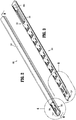
- Surgical clip applier 100 in accordance with an embodiment of the present disclosure is generally designated as 100. It is contemplated that any of the components of surgical clip applier 100 may be formed from any suitable biocompatible material such as stainless steel, titanium, or the like.
- Surgical clip applier 100 generally includes a handle assembly 102 including a housing 104 having upper housing half 104a and lower housing half 104b. Handle assembly 102 further includes a pair of handles 106pivotably secured to housing 104 and extending outwardly therefrom.
- a channel assembly 108 is fixedly secured to housing 104 and extends outwardly therefrom, terminating in and supporting a jaw assembly 110. As shown in FIG.
- housing halves 104a and 104b fit together by snap fit engagement with one another. It is further contemplated that housing halves 104a and 104b may be joined through one or more screws, rivets, or the like, or through the use of glues or other adhesives.
- handles 106 are pivotably secured to housing 104 by handle pivot posts 104d extending from lower housing half 104b and into respective distal apertures 106a formed in handles 106.
- Handle assembly 102 includes a link member 122 pivotally connected at a first end 122a thereof to each handle 106 at a pivot point 106b formed in a respective handle 106.
- a second end 122b of each link member 122 is pivotally connected to a respective pivot point 140b 1 , 140b 2 defined in side walls 140b of drive channel 140.
- channel assembly 108 includes an outer or lower channel 132 having a proximal end retained in housing 104, between upper and lower housing halves 104a, 104b.
- clip applier 100 includes a drive channel 140 reciprocally supported in and extending between housing 104 of handle assembly 102 and channel assembly 108.
- a proximal end of drive channel 140 is supported between upper and lower housing halves 104a, 104b of housing 104 and a distal end of drive channel 140 is supported by outer channel 132 of channel assembly 108.
- a distal end of drive channel 140 is a substantially box-shaped tube including a pair of spaced apart side walls 140b interconnecting a top wall 140a and a bottom wall 140c.
- the distal-most end of drive channel 140 includes a tongue 140e disposed between side walls 140b and extending from and between top wall 140a and bottom wall 140c.
- clip applier 100 further includes a biasing member 146, in the form of a compression spring, disposed within housing 104 so as to operatively surround an intermediate portion of drive channel 140 and to abut against an inner distal surface of housing 104.
- Biasing member 146 functions to generally maintain drive channel 140 in a retracted or proximal-most position.
- biasing member 146 functions to retract or facilitate retraction of drive channel 140 following formation of a surgical clip "C" positioned between jaws 120, and following release of handles 106.
- a proximal end of drive channel 140 supports a ratchet rack member 141 that is secured thereto, wherein ratchet rack member 141 is movable together with drive channel 140.
- Ratchet rack member 141 defines a first set of teeth 141a configured and adapted to engage with a first ratchet pawl 142a, and second set of teeth 141b (not shown) disposed on an opposite side thereof configured and adapted to engage a second ratchet pawl 142b.
- First and second ratchet pawls 142a, 142b are each pivotally supported in housing 104, with first and second ratchet pawls 142a, 142b being disposed on opposed sides of ratchet rack member 141.
- Rack member 141 and pawls 142a, 142b define a ratchet mechanism 144.
- rack member 141 In use, as drive channel 140 is moved axially, rack member 141 is also moved axially therewith.
- the series of rack teeth 141a, 141b have a length which allows respective pawls 142a, 142b to reverse and advance back over rack member 141 when rack member 141 changes between proximal and distal movement after drive channel 140 reaches a proximal-most or distal-most position.
- Each pawl 142a, 142b is pivotally supported in upper housing half 104a and lower housing half 104b at a location wherein each pawl 142a, 142b is in substantial operative engagement with respective rack teeth 141a, 141b of rack member 141.
- Pawls 142a, 142b are engageable with rack member 141 to restrict longitudinal movement of rack member 141 and, in turn, drive channel 140.
- Ratchet mechanism 144 includes a snap-over spring 143, in the form of a coil spring, interposed between pawls 142a, 142b and extending through and across rack member 141.
- Snap-over spring 143 functions to maintain the teeth of pawls 142a, 142b in engagement with the respective rack teeth 141a, 141b of rack member 141 as rack member 141 is axially translated.
- Clip applier 100 is provided with audible/tactile indication or feedback when pawls 142a, 142b are flipped at either end of the stroke of drive channel 140.
- pawls 142a, 142b flip pawls 142a, 142b are accelerated by snap-over spring 143 and slap against the walls of housing 104, thereby providing the user feedback that the end of a stroke has been reached.
- jaw assembly 110 of clip applier 100 includes a pair of jaws 120 mounted on or at a distal end of channel assembly 108 and actuatable by handles 106 of handle assembly 102.
- the pair of jaws 120 is formed of a suitable biocompatible material such as, for example, stainless steel or titanium.
- the pair of jaws 120 includes a first jaw member 121a, and a second jaw member 121b, which define a channel 121 there between for receipt of a surgical clip "Cl" therein.
- clip applier 100 further includes linkage mechanism 150 having a distal, driven link arm 154 having a first, distal end 154a selectively connectable to proximal end 160b of pusher bar 304 of clip cartridge assembly 300, as described in further detail below.
- Linkage mechanism 150 further includes a proximal, driver link arm 152 having a first, distal end 152a pivotally connected to a second, proximal end 154b of driven link arm 154, and a second, proximal end 152b defining an arcuate slot 152c configured to slidably receive a tab 140f of drive channel 140.
- Arcuate slot 152c is open ended and is only engaged by tab 140f of drive channel 140 during select portions of a distal and proximal translation thereof, as will be described in greater detail below.
- Driver link arm 152 is pivotally connected to outer channel 132 via a pin 126, such that driver link arm 152 is axially fixed with respect to outer channel 132.
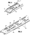
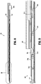
- Clip cartridge assembly 300 of surgical clip applier 100 is shown.
- Clip cartridge assembly 300 is configured to be selectively loadable into outer channel 132 of channel assembly 108, and to be actuated by handle assembly 102 to fire and form the surgical clips loaded therein onto underlying tissue and/or vessels.
- Each clip cartridge assembly 300 may be loaded with a particularly sized set of surgical clips (e.g, relatively small surgical clips, relatively medium surgical clips, or relatively large surgical clips).
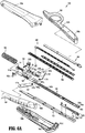
- Clip cartridge assembly 300 includes a clip tray 302 including base wall 302a and a pair of spaced apart side walls or rails 302b supported on base wall 302a. Base wall 302a and side walls 302b define a clip channel 302c.
- Clip tray 302 includes a linear array of distally extending resilient, deflectable fingers 302d projecting up from base wall 302a and into clip channel 302c at a location between side walls 302b.
- the distal-most deflectable finger 302d forms a single, rectangular finger configured to engage a backspan or crown of the distal-most clip "Cl" and nest between the spaced apart prongs 304d 1 , 304d 2 ( FIG. 5 ) of cartridge clip pusher bar 304, as discussed below.
- a pair of channels 302f are disposed on either side of the distal-most finger 302d and are configured to selectively receive each of the spaced apart prongs 304d 1 , 304d 2 ( FIG. 5 ) of clip pusher bar 304 when all of the surgical clips "C" have been formed, as will be discussed in further detail below.
- Each of the remaining proximal deflectable fingers 302d define a V-shaped configuration adapted to engage opposing sides of a backspan of each remaining clip of the stack of surgical clips "C” as illustrated in FIG. 7 .
- a slot or channel 306 ( FIGS. 3 and 6 ) is defined within the proximal end of base wall 302a such that the coupling stem 304c of cartridge clip pusher bar 304 may be slidably disposed therein, as discussed in further detail below.
- clip tray 302 further includes a pair of spaced apart, distally extending resilient deflectable prongs 302e projecting up from the proximal end of base wall 302a and into clip channel 302c at a location between side walls 302b.
- Each of the prongs 302e is spaced apart such that they are in slidable engagement with an inner portion of each leg of the distal-most clip "C1".
- Prongs 302e are dimensioned to engage the interior of a backspan of the clip "C", such that prongs 302e prevent the clip, proximal to the distal-most clip “Cl”, from advancing distally past prongs 302e when the distal-most clip “Cl” is being loaded into the pair of jaws 120.
- the biasing force provided by the prongs 302e is overcome when the distal-most clip “C” is urged distally by the cartridge clip pusher bar 304, and once the distal-most clip "Cl” has been loaded into the pair of jaws 120, each of the prongs 302e returns to their initial position to prevent the next clip "C” from advancing any further.
- Clip cartridge assembly 300 includes a cartridge clip pusher bar 304slidably disposed adjacent clip tray 302.
- Cartridge clip pusher bar 304 includes a proximal end 304adefining a coupling stem, head, or boss 304c configured to slidably protrude through channel 306 of clip tray 302 and selectively connect with distal end 154a of linkage mechanism 150.
- Cartridge clip pusher bar 304 further includes a distal end portion 304b defining a pusher 304d configured to engage a distal-most clip "Cl" of a stack of surgical clips "C” for loading the distal-most surgical clip "Cl” into the pair of jaws 120 of clip applier 100.
- Pusher 304d includes a pair of spaced apart prongs 304d 1 , 304d 2 ( FIG. 7 ) configured to engage a backspan of the distal-most surgical clip "Cl", as illustrated in FIGS. 4-5 .
- cartridge clip pusher bar 304 further includes a linear array of distally extending resilient, deflectable fingers 304e, with each finger 304e defining a rectangular profile including a distal shoulder 304f disposed on a distal end thereof.
- each of the deflectable fingers 302d of clip tray 302 is disposed axially between each deflectable finger 304e of cartridge clip pusher bar 304, such that each of deflectable fingers 302d, 304e are arranged in a tandem configuration when the clip pusher bar 304 is in a proximal position relative to clip tray 302.
- the V-shaped configuration of the proximal deflectable fingers 302d of clip tray 302 permits each proximal deflectable finger 304e of the cartridge clip pusher bar 304 to nest within the V-shape of the proximal deflectable fingers 302d such that distal shoulder 304f of deflectable finger 304e engages a backspan of each of the remaining surgical clips of the stack of surgical clips "C" as the cartridge clip pusher bar 304 is driven distally.
- Clip cartridge assembly 300 includes a stack of surgical clips "C” interposed between clip tray 302 and cartridge clip pusher bar 304.
- the stack of surgical clips “C” is supported on or loaded in clip tray 302 such that a crown or backspan of each surgical clip “C” is disposed distal of a respective deflectable finger 302d of clip tray 302. Further, when cartridge clip pusher bar 304 is in a proximal position relative to clip tray 302, each deflectable finger 304e is also disposed proximal of the crown or backspan of a respective clip of the stack of surgical clips "C” as discussed above.
- Clip cartridge assembly 300 may be loaded with 10 surgical clips “C", or, in embodiments, clip cartridge assembly 300 may be loaded with any number of surgical clips C", provided clip cartridge assembly 300and channel assembly 108 are appropriately configured and dimensioned.
- Surgical clips "C” may be fabricated from materials know by those skilled in the art, including and not limited to stainless steel, titanium, or other metal alloys. In an embodiment it is contemplated that at least a final surgical clip of the stack of surgical clips "C” may be dyed a particular color to indicate to the user when a final surgical clip of clip cartridge assembly 300 is loaded into the pair of jaws 120.
- channel cover 308 configured and adapted for connection and support on clip tray 302,may be snapped into engagement with rails 302b of clip tray 302 such that channel cover 308 is detachably secured thereto.
- Channel cover 308 is configured and adapted to provide a downward biasing force on cartridge clip pusher bar 304, thereby preventing cartridge clip pusher bar 304 from separating from clip tray 302 during operation.
- clip cartridge assembly 300 may be loaded into channel assembly 108.
- Clip cartridge assembly 300 is loaded into channel assembly 108 by initially placing coupling stem 304cof the cartridge clip pusher bar 304 into selective engagement with distal end 154a of linkage mechanism 150. Thereafter, the clip tray 302 is pushed into further engagement with the side walls of outer channel 132 of channel assembly 108 such that clip tray 302, and therefore, clip cartridge assembly 300, are detachably secured thereto.
- Clip tray 302 may be secured to outer channel 132 of channel assembly 108 by any suitable means, such as a detent, lips, or wings.
- wings extending along the side edges of outer channel 132 of channel assembly 108 and extending towards one another snap over or otherwise engage the lateral sides of clip tray 302 such that clip tray 302, and therefore, clip cartridge assembly 300, are detachably secured thereto.
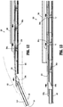
- clip applier 100 is illustrated with clip cartridge assembly 300 loaded in channel assembly 108 (as described above).
- the operation of clip applier 100 is substantially similar to that of the exemplary clip applier referenced hereinabove in U.S. Patent Application Publication No. 2014/0194903 , and therefore, in the interest of brevity, only the differences therebetween will be discussed hereinbelow.
- the cartridge clip pusher bar 304 of clip cartridge assembly 300 is moved in a distal direction to load distal-most clip "Cl” of the stack of surgical clips "C” in a distal direction and into the pair of jaws 120.
- the spaced apart prongs 304d 1 , 304d 2 of pusher 304d of cartridge clip pusher bar 304 engages the backspan of distal-most clip “Cl” and pushes distal-most clip "Cl” out of clip cartridge assembly 300 and into channel 121 of the pair of jaws 120.
- the distal movement of the distal-most clip “Cl” compresses each of the spaced apart prongs 302e of the clip tray 302, thereby permitting the distal-most clip “Cl” to be loaded within the pair of jaws 120, as described above.
- the prongs 302e return to their initial position and prevent the clips "C", proximal to the distal-most clip "Cl", from advancing further distally.
- distal shoulder 304f of finger 304eof cartridge clip pusher bar 304 abuts against a respective backspan of a respective surgical clip of the remaining surgical clips "C” to also urge the remaining surgical clips "C” in a distal direction, such that fingers 302d of the clip tray 302 are deflected, thereby permitting each of the remaining surgical clips "C” to advance distally to replace each respective surgical clip of the stack of surgical clips "C".
- the handles 106 are opened causing the drive channel 140 to retract proximally, thereby causing linkage mechanism 150 to impart a force acting in a proximal direction on coupling stem 304c, thereby drawing cartridge clip pusher bar 304 proximally over each of the remaining surgical clips of the clip stack "C".
- cartridge clip pusher bar 304 is moved in a proximal direction, fingers 304e abut against a distal surface of the backspans of the remaining surgical clips "C” to also urge the remaining surgical clips "C” in a proximal direction.
- Cartridge clip pusher bar 304 proximally retracts the remaining surgical clips "C” until each remaining surgical clip “C” is retracted into contact with a respective distal tip of a respective resilient, deflectable finger 302d of clip tray 302, which blocks or stops further proximal retraction of the remaining surgical clips "C".
- cartridge clip pusher bar 304 continues to be drawn proximally, concurrently, the spaced apart prongs 304d 1 , 304d 2 of pusher 304d and fingers 304e of cartridge clip pusher bar 304 are deflected up and over each of the remaining surgical clips "C” until cartridge clip pusher bar 304 returns to a proximal-most position.
- a nose 304g FIG.
- cartridge clip pusher bar 304 is biased towards, and is supported by, an upper surface of a backspan of the distal-most surgical clip "Cl", preventing each of the spaced apart prongs 304d 1 , 304d 2 of pusher 304d from engaging the pair of channels 302f of clip tray 302.
- FIG. 5 an exemplary mode of operation of a lockout safety mechanism is illustrated.
- surgical clip applier 100 is capable of loading different surgical clip cartridge assemblies 300 in channel assembly 108.
- channel assembly 108 may be loaded with a surgical clip cartridge assembly 300 that is loaded with a stack of surgical clips "C" having a first size, or channel assembly 108 may be loaded with a surgical clip cartridge assembly 300 that is loaded with a stack of surgical clips "C” having a second size different than the first size.
- the user or surgeon may load a surgical clip cartridge assembly 300, loaded with a particular size of surgical clips, depending on the particular surgical procedure to be performed. Additionally, during a surgical procedure, if the need arises to use a different sized surgical clip, the user or surgeon may eject or unload the surgical clip cartridge assembly 300 that is loaded in channel assembly 108and then load a new surgical clip cartridge assembly 300 (having a different sized stack of surgical clips loaded therein as compared to the unloaded surgical clip cartridge assembly 300) into channel assembly 108.
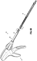
- surgical clip cartridge assembly 300 may be mated to a surgical clip applier 200 configured for use in endoscopic surgical procedures.
- Surgical clip applier 200 generally includes a handle assembly 400, and endoscopic assembly 500 including a shaft assembly 510 selectively connectable to and extendable distally from handle assembly 400, wherein the surgical clip cartridge assembly 300 is selectively loadable into shaft assembly 510 of endoscopic assembly 500.
- Assembly and operation of clip cartridge assembly 300 is identical to that which is described hereinabove, with the exception of being selectively attached to surgical clip applier 200.
- endoscopic surgical clip appliers configured for use with surgical clip cartridge assembly 300, reference may be made to China PCT Patent Application Serial No. PCT/CN2015/070733, filed on January 15, 2015 , (Atty. Docket: 355677 (203-10414).
- a surgical kit including a surgical clip applier 100 and a plurality of clip cartridge assemblies 300 including at least a first set of clip cartridge assemblies loaded with a stack of surgical clips having a first size and a second set of clip cartridge assemblies loaded with a stack of surgical clips having a second size different than the first size.
- the kit may include instructions for the assembly or surgical clip applier 100, the use of surgical clip applier 100, and the processing of surgical clip applier assembly 100 following use, a surgical clip applier 100 including a single handle assembly 102 and a single clip cartridge assembly 300, and a package, container or box configured to retain the same.
Claims (9)
- Klammer-Patronenanordnung (300), umfassend:eine Klammerschale (302), die dafür konfiguriert ist, selektiv in eine Kanalanordnung (108) eines chirurgischen Klammerapplikators (100) geladen werden zu können, wobei die Klammerschale (302) eine erste Vielzahl distal ausgerichteter, biegsamer, elastischer Finger (302d) umfasst, die von einer Basiswand (302a) derselben vorstehen;eine Patronenklammer-Schieberstange (304), die angrenzend an die Klammerschale (302) angeordnet und relativ dazu verschiebbar ist, wobei die Patronenklammer-Schieberstange (304) eine zweite Vielzahl distal ausgerichteter, biegsamer, elastischer Finger (304e), die von einer Basiswand davon vorstehen und jeweils in einer distalen Schulter (304f) enden, und einen Schieber, der ein Paar beabstandeter Zinken (304d) definiert, aufweist; undmehrere chirurgische Klammern ("C"), die zwischen der Klammerschale (302) und der Patronenklammer-Schieberstange (304) angeordnet sind, wobei eine chirurgische Klammer ("C") distal von jedem elastischen Finger (302d) der Klammerschale (302) angeordnet ist, wobei der am weitesten distal liegende Finger (302d) der ersten Mehrzahl von distal ausgerichteten, biegsamen, elastischen Fingern (302d) eine rechteckige Konfiguration aufweist, die dafür konfiguriert ist, mit einer Rückfläche oder einer Krone der am weitesten distal liegenden Klammer und der Aufnahme zwischen den beabstandeten Zinken in Eingriff zu kommen;und wobei jeder verbleibende Finger der ersten Vielzahl von distal ausgerichteten, biegsamen, elastischen Fingern (302d) eine V-förmige Kerbe aufweist, die in einem distalen Ende davon ausgebildet ist.
- Klammer-Patronenanordnung (300) nach Anspruch 1, wobei die Patronenklammer-Schieberstange (304) ferner einen Schaft (304c) aufweist, der an einem proximalen Ende (304a) der Patronenklammer-Schieberstange (304) angeordnet ist und von diesem vorsteht, wobei der Schaft (304c) so konfiguriert ist, dass er sich gleitend durch einen Kanal (306) erstreckt, der in einer Innenfläche der Klammerschale (302) definiert ist, wobei die Patronenklammer-Schieberstange (304) durch Kontakt mit dem Schaft (304c) der Patronenklammer-Schieberstange (304) distal relativ zu der Klammerschale (302) gedrückt wird.
- Klammer-Patronenanordnung (300) nach Anspruch 1 oder Anspruch 2, wobei eine distale Bewegung der Patronenklammer-Schieberstange (304) bewirkt, dass jede distale Schulter (304f) der Patronenklammer-Schieberstange (304) mit einer Rückfläche einer entsprechenden chirurgischen Klammer ("C") in Kontakt kommt, wodurch alle chirurgischen Klammern gleichzeitig distal vorgeschoben werden.
- Klammer-Patronenanordnung (300) nach Anspruch 2 oder Anspruch 3, wobei nach einer distalen Bewegung der Patronenklammer-Schieberstange (304) jede der zweiten Vielzahl von distal ausgerichteten, biegsamen elastischen Fingern (304e) die Rückfläche einer entsprechenden verbleibenden chirurgischen Klammer ("C") nach einer proximalen Bewegung der Patronenklammer-Schieberstange (304) berührt, um alle verbleibenden chirurgischen Klammern proximal zu bewegen, bis die Rückflächen aller verbleibenden chirurgischen Klammern einen entsprechenden Finger der ersten Vielzahl von distal ausgerichteten, biegsamen, elastischen Fingern (302d) der Klammerschale (302) berühren, um jede weitere proximale Bewegung der verbleibenden chirurgischen Klammern ("C") zu blockieren.
- Klammer-Patronenanordnung (300) nach einem der Ansprüche 1 bis 4, wobei die Klammerschale (302) ferner ein beabstandetes Paar distal ausgerichteter, biegsamer, elastischer Finger (302e) aufweist, die von einem distalen Ende der Basiswand (302a) derselben vorstehen, wobei das beabstandete Paar Finger (302e) so konfiguriert ist, dass es eine distale Oberfläche einer Rückfläche einer chirurgischen Klammer ("C") berührt, die durch die Patronenklammer-Schieberstange (304) distal gedrückt wird, wodurch jede weitere distale Bewegung der chirurgischen Klammer ("C") verhindert wird.
- Klammer-Patronenanordnung (300) nach einem der vorhergehenden Ansprüche, ferner umfassend eine Kanalabdeckung (308), die so konfiguriert ist, dass sie selektiv in die Klammerschale (302) eingreift, wobei die Kanalabdeckung (308) ferner so konfiguriert ist, dass sie eine Vorspannkraft auf die Patronenklammer-Schieberstange (304) ausübt, so dass die Patronenklammer-Schieberstange (304) in einer Position neben der Klammerschale (302) gehalten wird.
- Chirurgischer Klammer-Applikator (100), umfassend:ein Gehäuse (104);mindestens einen Griff (106), der schwenkbar mit dem Gehäuse (104) verbunden ist;eine Kanalanordnung (108), die sich distal vom Gehäuse (104) erstreckt;eine Klammer-Patronenanordnung (300) nach einem der Ansprüche 1 bis 6, die selektiv in die Kanalanordnung (108) geladen werden kann, wobei die Klammer-Patronenanordnung (300) in mechanischer Verbindung mit dem mindestens einen Griff (106) steht, wobei ein Backenpaar (120) an einem distalen Ende der Kanalanordnung (108) gelagert ist, wobei das Backenpaar dafür konfiguriert ist, eine einzelne, nicht geformte chirurgische Klammer ("C") darin aufzunehmen.
- Chirurgischer Klammer-Applikator nach Anspruch 7, ferner umfassend eine endoskopische Anordnung (500), die selektiv mit dem Gehäuse (104) verbindbar ist, wobei die Kanalanordnung (108) innerhalb der endoskopischen Anordnung (500) angeordnet ist.
- Chirurgischer Klammer-Applikator nach Anspruch 8, wobei das Backenpaar (120) an einem distalen Ende der endoskopischen Anordnung (500) gelagert ist.
Applications Claiming Priority (1)
| Application Number | Priority Date | Filing Date | Title |
|---|---|---|---|
| PCT/CN2015/071089 WO2016115676A1 (en) | 2015-01-20 | 2015-01-20 | Surgical clip applier with multiple clip feeding mechanism |
Publications (3)
| Publication Number | Publication Date |
|---|---|
| EP3247286A1 EP3247286A1 (de) | 2017-11-29 |
| EP3247286A4 EP3247286A4 (de) | 2018-10-17 |
| EP3247286B1 true EP3247286B1 (de) | 2020-05-06 |
Family
ID=56416262
Family Applications (1)
| Application Number | Title | Priority Date | Filing Date |
|---|---|---|---|
| EP15878354.8A Active EP3247286B1 (de) | 2015-01-20 | 2015-01-20 | Applikator fuer chirurgische klammern mit mechanismus zur zuführung mehrerer klammern |
Country Status (6)
| Country | Link |
|---|---|
| US (1) | US20170340331A1 (de) |
| EP (1) | EP3247286B1 (de) |
| JP (1) | JP2018505729A (de) |
| CN (1) | CN107205748B (de) |
| CA (1) | CA2972657A1 (de) |
| WO (1) | WO2016115676A1 (de) |
Families Citing this family (81)
| Publication number | Priority date | Publication date | Assignee | Title |
|---|---|---|---|---|
| EP2875786B1 (de) | 2004-10-08 | 2017-02-01 | Covidien LP | Vorrichtung zur Anwendung chirurgischer Klammern |
| AU2005294209B2 (en) | 2004-10-08 | 2011-04-07 | Covidien Lp | Endoscopic surgical clip applier |
| CA2605135C (en) | 2006-10-17 | 2014-12-30 | Tyco Healthcare Group Lp | Apparatus for applying surgical clips |
| EP3189796B1 (de) | 2007-03-26 | 2019-09-25 | Covidien LP | Endoskopischer operationsklemmen-applikator |
| AU2008240272B2 (en) | 2007-04-11 | 2013-08-29 | Covidien Lp | Surgical clip applier |
| US8465502B2 (en) | 2008-08-25 | 2013-06-18 | Covidien Lp | Surgical clip applier and method of assembly |
| US8267944B2 (en) | 2008-08-29 | 2012-09-18 | Tyco Healthcare Group Lp | Endoscopic surgical clip applier with lock out |
| US9358015B2 (en) | 2008-08-29 | 2016-06-07 | Covidien Lp | Endoscopic surgical clip applier with wedge plate |
| US8409223B2 (en) | 2008-08-29 | 2013-04-02 | Covidien Lp | Endoscopic surgical clip applier with clip retention |
| US8545486B2 (en) | 2009-12-15 | 2013-10-01 | Covidien Lp | Surgical clip applier |
| US8403945B2 (en) | 2010-02-25 | 2013-03-26 | Covidien Lp | Articulating endoscopic surgical clip applier |
| US8968337B2 (en) | 2010-07-28 | 2015-03-03 | Covidien Lp | Articulating clip applier |
| US9186153B2 (en) | 2011-01-31 | 2015-11-17 | Covidien Lp | Locking cam driver and jaw assembly for clip applier |
| US20130131697A1 (en) | 2011-11-21 | 2013-05-23 | Covidien Lp | Surgical clip applier |
| US9364216B2 (en) | 2011-12-29 | 2016-06-14 | Covidien Lp | Surgical clip applier with integrated clip counter |
| US9408610B2 (en) | 2012-05-04 | 2016-08-09 | Covidien Lp | Surgical clip applier with dissector |
| US9532787B2 (en) | 2012-05-31 | 2017-01-03 | Covidien Lp | Endoscopic clip applier |
| US9113892B2 (en) | 2013-01-08 | 2015-08-25 | Covidien Lp | Surgical clip applier |
| US9750500B2 (en) | 2013-01-18 | 2017-09-05 | Covidien Lp | Surgical clip applier |
| US9775624B2 (en) | 2013-08-27 | 2017-10-03 | Covidien Lp | Surgical clip applier |
| US10702278B2 (en) | 2014-12-02 | 2020-07-07 | Covidien Lp | Laparoscopic surgical ligation clip applier |
| US9931124B2 (en) | 2015-01-07 | 2018-04-03 | Covidien Lp | Reposable clip applier |
| WO2016112509A1 (en) | 2015-01-15 | 2016-07-21 | Covidien Lp | Endoscopic reposable surgical clip applier |
| US10292712B2 (en) | 2015-01-28 | 2019-05-21 | Covidien Lp | Surgical clip applier with integrated cutter |
| US10159491B2 (en) | 2015-03-10 | 2018-12-25 | Covidien Lp | Endoscopic reposable surgical clip applier |
| US10660652B2 (en) | 2015-10-10 | 2020-05-26 | Covidien Lp | Endoscopic surgical clip applier |
| WO2017075752A1 (en) | 2015-11-03 | 2017-05-11 | Covidien Lp | Endoscopic surgical clip applier |
| US10905425B2 (en) | 2015-11-10 | 2021-02-02 | Covidien Lp | Endoscopic reposable surgical clip applier |
| US10390831B2 (en) | 2015-11-10 | 2019-08-27 | Covidien Lp | Endoscopic reposable surgical clip applier |
| WO2017120734A1 (en) | 2016-01-11 | 2017-07-20 | Covidien Lp | Endoscopic reposable surgical clip applier |
| AU2016388454A1 (en) | 2016-01-18 | 2018-07-19 | Covidien Lp | Endoscopic surgical clip applier |
| CA2958160A1 (en) | 2016-02-24 | 2017-08-24 | Covidien Lp | Endoscopic reposable surgical clip applier |
| WO2018027788A1 (en) | 2016-08-11 | 2018-02-15 | Covidien Lp | Endoscopic surgical clip applier and clip applying systems |
| WO2018035796A1 (en) | 2016-08-25 | 2018-03-01 | Covidien Lp | Endoscopic surgical clip applier and clip applying systems |
| US10639044B2 (en) | 2016-10-31 | 2020-05-05 | Covidien Lp | Ligation clip module and clip applier |
| US10660651B2 (en) | 2016-10-31 | 2020-05-26 | Covidien Lp | Endoscopic reposable surgical clip applier |
| US10610236B2 (en) | 2016-11-01 | 2020-04-07 | Covidien Lp | Endoscopic reposable surgical clip applier |
| US10492795B2 (en) | 2016-11-01 | 2019-12-03 | Covidien Lp | Endoscopic surgical clip applier |
| US10426489B2 (en) | 2016-11-01 | 2019-10-01 | Covidien Lp | Endoscopic reposable surgical clip applier |
| US10709455B2 (en) | 2017-02-02 | 2020-07-14 | Covidien Lp | Endoscopic surgical clip applier |
| US10758244B2 (en) | 2017-02-06 | 2020-09-01 | Covidien Lp | Endoscopic surgical clip applier |
| AU2017397500A1 (en) | 2017-02-06 | 2019-07-11 | Covidien Lp | Surgical clip applier with user feedback feature |
| US10660725B2 (en) | 2017-02-14 | 2020-05-26 | Covidien Lp | Endoscopic surgical clip applier including counter assembly |
| US10603038B2 (en) | 2017-02-22 | 2020-03-31 | Covidien Lp | Surgical clip applier including inserts for jaw assembly |
| US11583291B2 (en) | 2017-02-23 | 2023-02-21 | Covidien Lp | Endoscopic surgical clip applier |
| US10548602B2 (en) | 2017-02-23 | 2020-02-04 | Covidien Lp | Endoscopic surgical clip applier |
| US10675112B2 (en) | 2017-08-07 | 2020-06-09 | Covidien Lp | Endoscopic surgical clip applier including counter assembly |
| US10932790B2 (en) | 2017-08-08 | 2021-03-02 | Covidien Lp | Geared actuation mechanism and surgical clip applier including the same |
| US10786262B2 (en) | 2017-08-09 | 2020-09-29 | Covidien Lp | Endoscopic reposable surgical clip applier |
| US10786263B2 (en) | 2017-08-15 | 2020-09-29 | Covidien Lp | Endoscopic reposable surgical clip applier |
| US10835341B2 (en) | 2017-09-12 | 2020-11-17 | Covidien Lp | Endoscopic surgical clip applier and handle assemblies for use therewith |
| US10758245B2 (en) | 2017-09-13 | 2020-09-01 | Covidien Lp | Clip counting mechanism for surgical clip applier |
| US10653429B2 (en) | 2017-09-13 | 2020-05-19 | Covidien Lp | Endoscopic surgical clip applier |
| US10835260B2 (en) | 2017-09-13 | 2020-11-17 | Covidien Lp | Endoscopic surgical clip applier and handle assemblies for use therewith |
| US11116513B2 (en) | 2017-11-03 | 2021-09-14 | Covidien Lp | Modular surgical clip cartridge |
| US11376015B2 (en) | 2017-11-03 | 2022-07-05 | Covidien Lp | Endoscopic surgical clip applier and handle assemblies for use therewith |
| US10828036B2 (en) | 2017-11-03 | 2020-11-10 | Covidien Lp | Endoscopic surgical clip applier and handle assemblies for use therewith |
| US10945734B2 (en) | 2017-11-03 | 2021-03-16 | Covidien Lp | Rotation knob assemblies and surgical instruments including the same |
| US10932791B2 (en) | 2017-11-03 | 2021-03-02 | Covidien Lp | Reposable multi-fire surgical clip applier |
| US10722236B2 (en) | 2017-12-12 | 2020-07-28 | Covidien Lp | Endoscopic reposable surgical clip applier |
| US10849630B2 (en) | 2017-12-13 | 2020-12-01 | Covidien Lp | Reposable multi-fire surgical clip applier |
| US10743887B2 (en) | 2017-12-13 | 2020-08-18 | Covidien Lp | Reposable multi-fire surgical clip applier |
| US10959737B2 (en) | 2017-12-13 | 2021-03-30 | Covidien Lp | Reposable multi-fire surgical clip applier |
| US11051827B2 (en) | 2018-01-16 | 2021-07-06 | Covidien Lp | Endoscopic surgical instrument and handle assemblies for use therewith |
| US10993721B2 (en) | 2018-04-25 | 2021-05-04 | Covidien Lp | Surgical clip applier |
| US10786273B2 (en) | 2018-07-13 | 2020-09-29 | Covidien Lp | Rotation knob assemblies for handle assemblies |
| US11246601B2 (en) | 2018-08-13 | 2022-02-15 | Covidien Lp | Elongated assemblies for surgical clip appliers and surgical clip appliers incorporating the same |
| US11344316B2 (en) | 2018-08-13 | 2022-05-31 | Covidien Lp | Elongated assemblies for surgical clip appliers and surgical clip appliers incorporating the same |
| US11051828B2 (en) | 2018-08-13 | 2021-07-06 | Covidien Lp | Rotation knob assemblies and surgical instruments including same |
| US11219463B2 (en) | 2018-08-13 | 2022-01-11 | Covidien Lp | Bilateral spring for surgical instruments and surgical instruments including the same |
| US11278267B2 (en) | 2018-08-13 | 2022-03-22 | Covidien Lp | Latch assemblies and surgical instruments including the same |
| US11147566B2 (en) | 2018-10-01 | 2021-10-19 | Covidien Lp | Endoscopic surgical clip applier |
| CN111227898B (zh) * | 2018-11-29 | 2022-02-18 | 苏州英途康医疗科技有限公司 | 夹仓组件及施夹钳 |
| CN111248971B (zh) * | 2018-11-30 | 2021-06-29 | 苏州英途康医疗科技有限公司 | 医疗器械 |
| CN111248972B (zh) * | 2018-11-30 | 2021-05-28 | 苏州英途康医疗科技有限公司 | 医疗器械 |
| US11524398B2 (en) | 2019-03-19 | 2022-12-13 | Covidien Lp | Gear drive mechanisms for surgical instruments |
| CN112089470A (zh) * | 2019-06-18 | 2020-12-18 | 迈斯科生化科技有限公司 | 施夹器的夹钉推送结构 |
| CN112704535B (zh) * | 2019-10-25 | 2022-11-25 | 苏州英途康医疗科技有限公司 | 夹仓装置及外科手术器械 |
| US11779340B2 (en) | 2020-01-02 | 2023-10-10 | Covidien Lp | Ligation clip loading device |
| US11723669B2 (en) | 2020-01-08 | 2023-08-15 | Covidien Lp | Clip applier with clip cartridge interface |
| TWI797043B (zh) * | 2022-08-04 | 2023-03-21 | 台灣先進手術醫療器材股份有限公司 | 具鎖定結構的血管施夾裝置 |
Family Cites Families (15)
| Publication number | Priority date | Publication date | Assignee | Title |
|---|---|---|---|---|
| US4500024A (en) * | 1980-11-19 | 1985-02-19 | Ethicon, Inc. | Multiple clip applier |
| US4491133A (en) * | 1982-02-05 | 1985-01-01 | Ethicon, Inc. | Folding cartridge for a multiple clip applier |
| US4509518A (en) * | 1982-02-17 | 1985-04-09 | United States Surgical Corporation | Apparatus for applying surgical clips |
| US5030226A (en) * | 1988-01-15 | 1991-07-09 | United States Surgical Corporation | Surgical clip applicator |
| DE19603889C2 (de) * | 1996-02-03 | 1999-05-06 | Aesculap Ag & Co Kg | Chirurgisches Anlegegerät |
| CA2359578A1 (en) * | 1999-01-25 | 2000-07-27 | Gary M. Johnson | Modular ligating apparatus and method |
| US7887553B2 (en) * | 2001-07-09 | 2011-02-15 | Tyco Healthcare Group Lp | Right angle clip applier apparatus and method |
| DE102009018820A1 (de) * | 2009-04-24 | 2010-10-28 | Aesculap Ag | Magazin mit einer Vielzahl C-förmiger Ligaturklammern |
| US20130131697A1 (en) * | 2011-11-21 | 2013-05-23 | Covidien Lp | Surgical clip applier |
| US9931123B2 (en) * | 2011-12-21 | 2018-04-03 | Joseph W Blake, III | Surgical clip applier |
| US9364216B2 (en) * | 2011-12-29 | 2016-06-14 | Covidien Lp | Surgical clip applier with integrated clip counter |
| US20130172910A1 (en) * | 2011-12-29 | 2013-07-04 | Covidien Lp | Surgical clip applier |
| US9113892B2 (en) * | 2013-01-08 | 2015-08-25 | Covidien Lp | Surgical clip applier |
| US9706993B2 (en) * | 2013-03-08 | 2017-07-18 | Covidien Lp | Staple cartridge with shipping wedge |
| WO2016112509A1 (en) * | 2015-01-15 | 2016-07-21 | Covidien Lp | Endoscopic reposable surgical clip applier |
-
2015
- 2015-01-20 WO PCT/CN2015/071089 patent/WO2016115676A1/en active Application Filing
- 2015-01-20 CN CN201580073962.2A patent/CN107205748B/zh not_active Expired - Fee Related
- 2015-01-20 EP EP15878354.8A patent/EP3247286B1/de active Active
- 2015-01-20 JP JP2017537974A patent/JP2018505729A/ja active Pending
- 2015-01-20 CA CA2972657A patent/CA2972657A1/en not_active Abandoned
- 2015-01-20 US US15/535,102 patent/US20170340331A1/en not_active Abandoned
Non-Patent Citations (1)
| Title |
|---|
| None * |
Also Published As
| Publication number | Publication date |
|---|---|
| CN107205748B (zh) | 2020-09-25 |
| US20170340331A1 (en) | 2017-11-30 |
| EP3247286A1 (de) | 2017-11-29 |
| CA2972657A1 (en) | 2016-07-28 |
| JP2018505729A (ja) | 2018-03-01 |
| EP3247286A4 (de) | 2018-10-17 |
| CN107205748A (zh) | 2017-09-26 |
| WO2016115676A1 (en) | 2016-07-28 |
Similar Documents
| Publication | Publication Date | Title |
|---|---|---|
| EP3247286B1 (de) | Applikator fuer chirurgische klammern mit mechanismus zur zuführung mehrerer klammern | |
| WO2016206015A1 (en) | Surgical clip applier with multiple clip feeding mechanism | |
| US11478252B2 (en) | Endoscopic reposable surgical clip applier | |
| US10682146B2 (en) | Surgical clip applier | |
| US11278287B2 (en) | Surgical clip applier with integrated clip counter | |
| US11464521B2 (en) | Reposable multi-fire surgical clip applier | |
| US10743886B2 (en) | Surgical clip applier | |
| US10709455B2 (en) | Endoscopic surgical clip applier | |
| US9414844B2 (en) | Surgical clip appliers | |
| US10758244B2 (en) | Endoscopic surgical clip applier | |
| JP6498303B2 (ja) | 内視鏡リポーザブル外科手術用クリップアプライヤ | |
| CN105816217B (zh) | 具有集成切割器的手术施夹器 | |
| AU2006201384A1 (en) | Surgical clip advancement mechanism |
Legal Events
| Date | Code | Title | Description |
|---|---|---|---|
| STAA | Information on the status of an ep patent application or granted ep patent |
Free format text: STATUS: THE INTERNATIONAL PUBLICATION HAS BEEN MADE |
|
| PUAI | Public reference made under article 153(3) epc to a published international application that has entered the european phase |
Free format text: ORIGINAL CODE: 0009012 |
|
| STAA | Information on the status of an ep patent application or granted ep patent |
Free format text: STATUS: REQUEST FOR EXAMINATION WAS MADE |
|
| 17P | Request for examination filed |
Effective date: 20170818 |
|
| AK | Designated contracting states |
Kind code of ref document: A1 Designated state(s): AL AT BE BG CH CY CZ DE DK EE ES FI FR GB GR HR HU IE IS IT LI LT LU LV MC MK MT NL NO PL PT RO RS SE SI SK SM TR |
|
| AX | Request for extension of the european patent |
Extension state: BA ME |
|
| DAX | Request for extension of the european patent (deleted) | ||
| A4 | Supplementary search report drawn up and despatched |
Effective date: 20180919 |
|
| RIC1 | Information provided on ipc code assigned before grant |
Ipc: A61B 17/128 20060101AFI20180913BHEP Ipc: A61B 17/03 20060101ALI20180913BHEP |
|
| GRAJ | Information related to disapproval of communication of intention to grant by the applicant or resumption of examination proceedings by the epo deleted |
Free format text: ORIGINAL CODE: EPIDOSDIGR1 |
|
| STAA | Information on the status of an ep patent application or granted ep patent |
Free format text: STATUS: GRANT OF PATENT IS INTENDED |
|
| GRAP | Despatch of communication of intention to grant a patent |
Free format text: ORIGINAL CODE: EPIDOSNIGR1 |
|
| INTG | Intention to grant announced |
Effective date: 20200102 |
|
| RIN1 | Information on inventor provided before grant (corrected) |
Inventor name: XU, SHUNHONG Inventor name: CAI, LONGSHENG Inventor name: CHEN, LIN Inventor name: HU, ENCHENG Inventor name: TAN, YUANDONG |
|
| GRAS | Grant fee paid |
Free format text: ORIGINAL CODE: EPIDOSNIGR3 |
|
| GRAA | (expected) grant |
Free format text: ORIGINAL CODE: 0009210 |
|
| STAA | Information on the status of an ep patent application or granted ep patent |
Free format text: STATUS: THE PATENT HAS BEEN GRANTED |
|
| AK | Designated contracting states |
Kind code of ref document: B1 Designated state(s): AL AT BE BG CH CY CZ DE DK EE ES FI FR GB GR HR HU IE IS IT LI LT LU LV MC MK MT NL NO PL PT RO RS SE SI SK SM TR |
|
| REG | Reference to a national code |
Ref country code: GB Ref legal event code: FG4D |
|
| REG | Reference to a national code |
Ref country code: AT Ref legal event code: REF Ref document number: 1265524 Country of ref document: AT Kind code of ref document: T Effective date: 20200515 Ref country code: CH Ref legal event code: EP |
|
| REG | Reference to a national code |
Ref country code: IE Ref legal event code: FG4D |
|
| REG | Reference to a national code |
Ref country code: DE Ref legal event code: R096 Ref document number: 602015052557 Country of ref document: DE |
|
| REG | Reference to a national code |
Ref country code: LT Ref legal event code: MG4D |
|
| REG | Reference to a national code |
Ref country code: NL Ref legal event code: MP Effective date: 20200506 |
|
| PG25 | Lapsed in a contracting state [announced via postgrant information from national office to epo] |
Ref country code: FI Free format text: LAPSE BECAUSE OF FAILURE TO SUBMIT A TRANSLATION OF THE DESCRIPTION OR TO PAY THE FEE WITHIN THE PRESCRIBED TIME-LIMIT Effective date: 20200506 Ref country code: NO Free format text: LAPSE BECAUSE OF FAILURE TO SUBMIT A TRANSLATION OF THE DESCRIPTION OR TO PAY THE FEE WITHIN THE PRESCRIBED TIME-LIMIT Effective date: 20200806 Ref country code: PT Free format text: LAPSE BECAUSE OF FAILURE TO SUBMIT A TRANSLATION OF THE DESCRIPTION OR TO PAY THE FEE WITHIN THE PRESCRIBED TIME-LIMIT Effective date: 20200907 Ref country code: IS Free format text: LAPSE BECAUSE OF FAILURE TO SUBMIT A TRANSLATION OF THE DESCRIPTION OR TO PAY THE FEE WITHIN THE PRESCRIBED TIME-LIMIT Effective date: 20200906 Ref country code: SE Free format text: LAPSE BECAUSE OF FAILURE TO SUBMIT A TRANSLATION OF THE DESCRIPTION OR TO PAY THE FEE WITHIN THE PRESCRIBED TIME-LIMIT Effective date: 20200506 Ref country code: GR Free format text: LAPSE BECAUSE OF FAILURE TO SUBMIT A TRANSLATION OF THE DESCRIPTION OR TO PAY THE FEE WITHIN THE PRESCRIBED TIME-LIMIT Effective date: 20200807 Ref country code: LT Free format text: LAPSE BECAUSE OF FAILURE TO SUBMIT A TRANSLATION OF THE DESCRIPTION OR TO PAY THE FEE WITHIN THE PRESCRIBED TIME-LIMIT Effective date: 20200506 |
|
| PG25 | Lapsed in a contracting state [announced via postgrant information from national office to epo] |
Ref country code: LV Free format text: LAPSE BECAUSE OF FAILURE TO SUBMIT A TRANSLATION OF THE DESCRIPTION OR TO PAY THE FEE WITHIN THE PRESCRIBED TIME-LIMIT Effective date: 20200506 Ref country code: BG Free format text: LAPSE BECAUSE OF FAILURE TO SUBMIT A TRANSLATION OF THE DESCRIPTION OR TO PAY THE FEE WITHIN THE PRESCRIBED TIME-LIMIT Effective date: 20200806 Ref country code: RS Free format text: LAPSE BECAUSE OF FAILURE TO SUBMIT A TRANSLATION OF THE DESCRIPTION OR TO PAY THE FEE WITHIN THE PRESCRIBED TIME-LIMIT Effective date: 20200506 Ref country code: HR Free format text: LAPSE BECAUSE OF FAILURE TO SUBMIT A TRANSLATION OF THE DESCRIPTION OR TO PAY THE FEE WITHIN THE PRESCRIBED TIME-LIMIT Effective date: 20200506 |
|
| REG | Reference to a national code |
Ref country code: AT Ref legal event code: MK05 Ref document number: 1265524 Country of ref document: AT Kind code of ref document: T Effective date: 20200506 |
|
| PG25 | Lapsed in a contracting state [announced via postgrant information from national office to epo] |
Ref country code: NL Free format text: LAPSE BECAUSE OF FAILURE TO SUBMIT A TRANSLATION OF THE DESCRIPTION OR TO PAY THE FEE WITHIN THE PRESCRIBED TIME-LIMIT Effective date: 20200506 Ref country code: AL Free format text: LAPSE BECAUSE OF FAILURE TO SUBMIT A TRANSLATION OF THE DESCRIPTION OR TO PAY THE FEE WITHIN THE PRESCRIBED TIME-LIMIT Effective date: 20200506 |
|
| PG25 | Lapsed in a contracting state [announced via postgrant information from national office to epo] |
Ref country code: DK Free format text: LAPSE BECAUSE OF FAILURE TO SUBMIT A TRANSLATION OF THE DESCRIPTION OR TO PAY THE FEE WITHIN THE PRESCRIBED TIME-LIMIT Effective date: 20200506 Ref country code: IT Free format text: LAPSE BECAUSE OF FAILURE TO SUBMIT A TRANSLATION OF THE DESCRIPTION OR TO PAY THE FEE WITHIN THE PRESCRIBED TIME-LIMIT Effective date: 20200506 Ref country code: CZ Free format text: LAPSE BECAUSE OF FAILURE TO SUBMIT A TRANSLATION OF THE DESCRIPTION OR TO PAY THE FEE WITHIN THE PRESCRIBED TIME-LIMIT Effective date: 20200506 Ref country code: ES Free format text: LAPSE BECAUSE OF FAILURE TO SUBMIT A TRANSLATION OF THE DESCRIPTION OR TO PAY THE FEE WITHIN THE PRESCRIBED TIME-LIMIT Effective date: 20200506 Ref country code: RO Free format text: LAPSE BECAUSE OF FAILURE TO SUBMIT A TRANSLATION OF THE DESCRIPTION OR TO PAY THE FEE WITHIN THE PRESCRIBED TIME-LIMIT Effective date: 20200506 Ref country code: AT Free format text: LAPSE BECAUSE OF FAILURE TO SUBMIT A TRANSLATION OF THE DESCRIPTION OR TO PAY THE FEE WITHIN THE PRESCRIBED TIME-LIMIT Effective date: 20200506 Ref country code: SM Free format text: LAPSE BECAUSE OF FAILURE TO SUBMIT A TRANSLATION OF THE DESCRIPTION OR TO PAY THE FEE WITHIN THE PRESCRIBED TIME-LIMIT Effective date: 20200506 Ref country code: EE Free format text: LAPSE BECAUSE OF FAILURE TO SUBMIT A TRANSLATION OF THE DESCRIPTION OR TO PAY THE FEE WITHIN THE PRESCRIBED TIME-LIMIT Effective date: 20200506 |
|
| PGFP | Annual fee paid to national office [announced via postgrant information from national office to epo] |
Ref country code: GB Payment date: 20201218 Year of fee payment: 7 Ref country code: FR Payment date: 20201217 Year of fee payment: 7 |
|
| REG | Reference to a national code |
Ref country code: DE Ref legal event code: R097 Ref document number: 602015052557 Country of ref document: DE |
|
| PG25 | Lapsed in a contracting state [announced via postgrant information from national office to epo] |
Ref country code: SK Free format text: LAPSE BECAUSE OF FAILURE TO SUBMIT A TRANSLATION OF THE DESCRIPTION OR TO PAY THE FEE WITHIN THE PRESCRIBED TIME-LIMIT Effective date: 20200506 Ref country code: PL Free format text: LAPSE BECAUSE OF FAILURE TO SUBMIT A TRANSLATION OF THE DESCRIPTION OR TO PAY THE FEE WITHIN THE PRESCRIBED TIME-LIMIT Effective date: 20200506 |
|
| PLBE | No opposition filed within time limit |
Free format text: ORIGINAL CODE: 0009261 |
|
| STAA | Information on the status of an ep patent application or granted ep patent |
Free format text: STATUS: NO OPPOSITION FILED WITHIN TIME LIMIT |
|
| 26N | No opposition filed |
Effective date: 20210209 |
|
| PG25 | Lapsed in a contracting state [announced via postgrant information from national office to epo] |
Ref country code: SI Free format text: LAPSE BECAUSE OF FAILURE TO SUBMIT A TRANSLATION OF THE DESCRIPTION OR TO PAY THE FEE WITHIN THE PRESCRIBED TIME-LIMIT Effective date: 20200506 |
|
| PGFP | Annual fee paid to national office [announced via postgrant information from national office to epo] |
Ref country code: DE Payment date: 20201217 Year of fee payment: 7 |
|
| PG25 | Lapsed in a contracting state [announced via postgrant information from national office to epo] |
Ref country code: MC Free format text: LAPSE BECAUSE OF FAILURE TO SUBMIT A TRANSLATION OF THE DESCRIPTION OR TO PAY THE FEE WITHIN THE PRESCRIBED TIME-LIMIT Effective date: 20200506 |
|
| REG | Reference to a national code |
Ref country code: CH Ref legal event code: PL |
|
| PG25 | Lapsed in a contracting state [announced via postgrant information from national office to epo] |
Ref country code: LU Free format text: LAPSE BECAUSE OF NON-PAYMENT OF DUE FEES Effective date: 20210120 |
|
| REG | Reference to a national code |
Ref country code: BE Ref legal event code: MM Effective date: 20210131 |
|
| PG25 | Lapsed in a contracting state [announced via postgrant information from national office to epo] |
Ref country code: LI Free format text: LAPSE BECAUSE OF NON-PAYMENT OF DUE FEES Effective date: 20210131 Ref country code: CH Free format text: LAPSE BECAUSE OF NON-PAYMENT OF DUE FEES Effective date: 20210131 |
|
| PG25 | Lapsed in a contracting state [announced via postgrant information from national office to epo] |
Ref country code: IE Free format text: LAPSE BECAUSE OF NON-PAYMENT OF DUE FEES Effective date: 20210120 |
|
| PG25 | Lapsed in a contracting state [announced via postgrant information from national office to epo] |
Ref country code: BE Free format text: LAPSE BECAUSE OF NON-PAYMENT OF DUE FEES Effective date: 20210131 |
|
| REG | Reference to a national code |
Ref country code: DE Ref legal event code: R119 Ref document number: 602015052557 Country of ref document: DE |
|
| GBPC | Gb: european patent ceased through non-payment of renewal fee |
Effective date: 20220120 |
|
| PG25 | Lapsed in a contracting state [announced via postgrant information from national office to epo] |
Ref country code: GB Free format text: LAPSE BECAUSE OF NON-PAYMENT OF DUE FEES Effective date: 20220120 Ref country code: DE Free format text: LAPSE BECAUSE OF NON-PAYMENT OF DUE FEES Effective date: 20220802 |
|
| PG25 | Lapsed in a contracting state [announced via postgrant information from national office to epo] |
Ref country code: FR Free format text: LAPSE BECAUSE OF NON-PAYMENT OF DUE FEES Effective date: 20220131 |
|
| PG25 | Lapsed in a contracting state [announced via postgrant information from national office to epo] |
Ref country code: HU Free format text: LAPSE BECAUSE OF FAILURE TO SUBMIT A TRANSLATION OF THE DESCRIPTION OR TO PAY THE FEE WITHIN THE PRESCRIBED TIME-LIMIT; INVALID AB INITIO Effective date: 20150120 |
|
| PG25 | Lapsed in a contracting state [announced via postgrant information from national office to epo] |
Ref country code: CY Free format text: LAPSE BECAUSE OF FAILURE TO SUBMIT A TRANSLATION OF THE DESCRIPTION OR TO PAY THE FEE WITHIN THE PRESCRIBED TIME-LIMIT Effective date: 20200506 |
|
| PG25 | Lapsed in a contracting state [announced via postgrant information from national office to epo] |
Ref country code: MK Free format text: LAPSE BECAUSE OF FAILURE TO SUBMIT A TRANSLATION OF THE DESCRIPTION OR TO PAY THE FEE WITHIN THE PRESCRIBED TIME-LIMIT Effective date: 20200506 |