EP3247003A1 - Electrical connector - Google Patents
Electrical connector Download PDFInfo
- Publication number
- EP3247003A1 EP3247003A1 EP17171965.1A EP17171965A EP3247003A1 EP 3247003 A1 EP3247003 A1 EP 3247003A1 EP 17171965 A EP17171965 A EP 17171965A EP 3247003 A1 EP3247003 A1 EP 3247003A1
- Authority
- EP
- European Patent Office
- Prior art keywords
- connector body
- connector
- staged position
- terminals
- electrical
- Prior art date
- Legal status (The legal status is an assumption and is not a legal conclusion. Google has not performed a legal analysis and makes no representation as to the accuracy of the status listed.)
- Granted
Links
- 239000007787 solid Substances 0.000 claims description 6
- 230000002401 inhibitory effect Effects 0.000 claims description 4
- 238000003780 insertion Methods 0.000 description 3
- 230000037431 insertion Effects 0.000 description 3
- 230000003213 activating effect Effects 0.000 description 2
- 239000004020 conductor Substances 0.000 description 2
- 230000003287 optical effect Effects 0.000 description 2
- 230000004913 activation Effects 0.000 description 1
- 238000013459 approach Methods 0.000 description 1
- 230000013011 mating Effects 0.000 description 1
Images


Classifications
-
- H—ELECTRICITY
- H01—ELECTRIC ELEMENTS
- H01R—ELECTRICALLY-CONDUCTIVE CONNECTIONS; STRUCTURAL ASSOCIATIONS OF A PLURALITY OF MUTUALLY-INSULATED ELECTRICAL CONNECTING ELEMENTS; COUPLING DEVICES; CURRENT COLLECTORS
- H01R13/00—Details of coupling devices of the kinds covered by groups H01R12/70 or H01R24/00 - H01R33/00
- H01R13/62—Means for facilitating engagement or disengagement of coupling parts or for holding them in engagement
- H01R13/639—Additional means for holding or locking coupling parts together, after engagement, e.g. separate keylock, retainer strap
-
- H—ELECTRICITY
- H01—ELECTRIC ELEMENTS
- H01R—ELECTRICALLY-CONDUCTIVE CONNECTIONS; STRUCTURAL ASSOCIATIONS OF A PLURALITY OF MUTUALLY-INSULATED ELECTRICAL CONNECTING ELEMENTS; COUPLING DEVICES; CURRENT COLLECTORS
- H01R13/00—Details of coupling devices of the kinds covered by groups H01R12/70 or H01R24/00 - H01R33/00
- H01R13/62—Means for facilitating engagement or disengagement of coupling parts or for holding them in engagement
- H01R13/627—Snap or like fastening
- H01R13/6271—Latching means integral with the housing
- H01R13/6272—Latching means integral with the housing comprising a single latching arm
-
- H—ELECTRICITY
- H01—ELECTRIC ELEMENTS
- H01R—ELECTRICALLY-CONDUCTIVE CONNECTIONS; STRUCTURAL ASSOCIATIONS OF A PLURALITY OF MUTUALLY-INSULATED ELECTRICAL CONNECTING ELEMENTS; COUPLING DEVICES; CURRENT COLLECTORS
- H01R13/00—Details of coupling devices of the kinds covered by groups H01R12/70 or H01R24/00 - H01R33/00
- H01R13/66—Structural association with built-in electrical component
- H01R13/665—Structural association with built-in electrical component with built-in electronic circuit
- H01R13/6666—Structural association with built-in electrical component with built-in electronic circuit with built-in overvoltage protection
-
- H—ELECTRICITY
- H01—ELECTRIC ELEMENTS
- H01R—ELECTRICALLY-CONDUCTIVE CONNECTIONS; STRUCTURAL ASSOCIATIONS OF A PLURALITY OF MUTUALLY-INSULATED ELECTRICAL CONNECTING ELEMENTS; COUPLING DEVICES; CURRENT COLLECTORS
- H01R13/00—Details of coupling devices of the kinds covered by groups H01R12/70 or H01R24/00 - H01R33/00
- H01R13/62—Means for facilitating engagement or disengagement of coupling parts or for holding them in engagement
- H01R13/639—Additional means for holding or locking coupling parts together, after engagement, e.g. separate keylock, retainer strap
- H01R13/6397—Additional means for holding or locking coupling parts together, after engagement, e.g. separate keylock, retainer strap with means for preventing unauthorised use
Definitions
- the invention generally relates to connector systems and more particularly relates to a connector system configured to retain the connector system in both a mechanically connected and electrically unconnected (pre-staged) condition and a mechanically and electrically connected (staged) condition.
- Connector bodies of connection systems have traditionally been designed to be easily inserted to one another with minimal engagement force needed to complete their mating. Once the connector bodies are successfully mated, the intent of a traditional connection system is to travel together easily with minimal effort and no secondary operation to complete the connection is required.
- connection is required to be locked in pre-staged position in which the connector bodies are mated but connector elements, such as electrical terminals, within the connector bodies are disconnected and not able to travel to a staged position in which the connector elements are connected or disconnected without a secondary operation being performed by an operator at the same time.
- the secondary operation is a requirement before being able to move the system to the staged position.
- an electrical connector system in accordance with one embodiment of this invention, includes a first connector body containing a first plurality of terminals and a second connector body containing a second plurality of terminals configured to interconnect with the first plurality of terminals.
- the second connector body is configured to receive the first connector body.
- the electrical connector system further includes a locking feature configured to secure the first connector body to the second connector body in a pre-staged position in which the first plurality of terminals is not connected to the second plurality of terminals and further configured to secure the first connector body to the second connector body in a staged position in which the first plurality of terminals is connected to the second plurality of terminals after disengaging the locking feature in the pre-staged condition.
- the locking feature may further include a latch defined by the first connector body having a leading edge and a trailing edge and a flexible lock arm pivotably attached to the second connector body by a resilient U-shaped strap.
- the lock arm is configured to engage the leading edge of the latch, thereby securing the first connector body in the pre-staged position.
- the lock arm is further configured to engage the trailing edge of the latch after disengaging the lock arm from the latch in the pre-staged condition, thereby securing the first connector body in the staged position.
- the leading edge of the latch may not be angled away from the lock arm.
- the locking feature may further include a stop defined by the first connector body and configured to engage the U-shaped strap, thereby inhibiting removal of the first connector body from the second connector body.
- the second connector body contains first and second electrical terminals attached to first and second wire cables respectively.
- the first connector body may contain a shunt connector that is configured to interconnect the first and second electrical terminals when the first and second connector bodies are in the staged position .
- the shunt connector is further configured to disconnect the first electrical terminal from the second electrical terminal when the first and second connector bodies are in the pre-staged position.
- the first and second wire cables may be connected to a high voltage interlock (HVIL) system.
- HVIL high voltage interlock
- the electrical connector system may further include a lock out feature that is configured to prevent the first connector body from being moved from the pre-staged position to the staged position regardless of the locking feature.
- the lock out feature may include a solid planar tab extending from the first connector body and a pair of perforated planar tabs extending from the second connector body each defining an aperture aligned with one another. The perforated planar tabs are arranged so that the solid planar tab can slide between the pair of perforated planar tabs as the first connector body is moved from the pre-staged to the staged position. An object inserted within the aperture will block the solid planar tab from sliding between the perforated planar tabs, thereby inhibiting the first connector body from being moved from the pre-staged position to the staged position.
- a connector system is presented herein.
- This connector system incorporates a lock-out feature that protects an operator from unintentionally moving the connector bodies of the connector system from a pre-staged position in which the connector bodies are mated but connector elements, such as electrical terminals, within the connector bodies are disconnected to staged position in which the connector elements are connected.
- the two connector bodies are locked together so that cannot be disconnected from one another but cannot be moved to the staged position without simultaneously activating a lock-out feature while pushing the two connector bodies together.
- Such a connector system may be used as part of a high voltage interlock (HVIL) system that controls whether an associated high voltage circuit, e.g.an output of a battery pack in an electrical vehicle, is energized based on the connection state of the connector system.
- HVIL high voltage interlock
- the connector system described herein addresses a problem of energizing the high voltage circuit due to inadvertent connection of the connector system that may pose causes a safety risk by adding a locking feature to the connection system that will not allow plug connector body to be moved from the pre-staged position to the staged position without activating the locking feature.
- Figs. 1 through 4 illustrate a non-limiting example of connector system 10 having a plug connector body 12, a socket connector body 14 configured to mate with the plug connector body 12, and a locking feature 16 that is configured to secure the plug connector body 12 to the socket connector body 14 in a pre-staged position 18 shown in Figs. 1 and 2 and further configured to secure the plug connector body 12 to the socket connector body 14 in a staged position 20 shown in Figs. 3 and 4 .
- the socket connector body 14 contains first and second female electrical terminals (not shown) that are connected to first and second wire cables (not shown) or other electrical conductors, e.g. bus bars or circuit board traces (not shown).
- the plug connector body 12 contains a shunt terminal (not shown) having two male pins (not shown) configured to interface with the female terminals that are electrically connected (shunted) to one another.
- the shunt terminal is not connected to any wire cables or other electrical conductors outside of the plug connector body 12.
- the socket connector body 14 includes a terminal housing 22 defining terminal cavities (not shown) extending through the terminal housing 22 for receiving the first and second female terminals therein.
- the socket connector body 14 also has a shroud 24 that at least partially surrounds the terminal housing 22 and can be integrally or separately connected to the terminal housing 22 in any suitable manner.
- the shroud 24 defines a socket for receiving the plug connector.
- the plug connector body 12 defines a lock tab 26 that extends outwardly from the plug connector body 12 and has a leading edge 26A and a trailing edge 26B designated relative to the direction of insertion of the plug connector body 12 into the shroud 24 of the socket connector body 14.
- the socket connector body 14 includes a longitudinally extending lock arm 28 pivotably attached to the socket connector body 14.
- a first end 28A of the lock arm 28 defines a lock nib 30 also having a leading edge 30A and a trailing edge 30B, again designated relative to the direction of insertion of the plug connector body 12 into the shroud 24 of the socket connector body 14.
- the lock arm 28 is integrally connected to the socket connector body 14 by a resilient U-shaped strap 32 that is configured to impose a hold-down force on the first end 28A of the lock arm 28 when the lock arm 28 is pivoted from a state of rest by pressing a second end 28B of the lock arm 28 opposite the first end 28A.
- a resilient U-shaped strap 32 that is configured to impose a hold-down force on the first end 28A of the lock arm 28 when the lock arm 28 is pivoted from a state of rest by pressing a second end 28B of the lock arm 28 opposite the first end 28A.
- the leading edge 26A of the lock tab 26 is substantially parallel to the leading edge 30A of the lock nib 30.
- substantially parallel means ⁇ 10° of absolutely parallel.
- the leading edge 26A of the lock tab 26 is substantially perpendicular to the surface of the plug connector body 12 from which it protrudes.
- substantially perpendicular means ⁇ 10° of absolutely perpendicular.
- the leading edge 30A of the lock nib 30 is also substantially perpendicular to the top surface of the lock arm 28.
- the leading edge 26A of the lock tab 26 is not angled away from the leading edge 30A of the lock nib 30. In other words, it's free from being angled away.
- leading edge 30A of the lock nib 30 is not angled toward the leading edge 26A of the lock tab 26.
- the leading edge of the lock tab may be angled toward the leading edge of the lock nib and the leading edge of the lock nib may be angled away from the leading edge of the lock tab.
- the trailing edge 26B of the lock tab 26 is substantially parallel to the trailing edge 30B of the lock nib 30.
- the trailing edge 26B of the lock tab 26 is substantially perpendicular to the surface of the plug connector body 12 from which it protrudes.
- the trailing edge 30B of the lock nib 30 is also substantially perpendicular to the top surface of the lock arm 28.
- the trailing edge 26B of the lock tab 26 is not angled away from the trailing edge 30B of the lock nib 30.
- the trailing edge 30B of the lock nib 30 is not angled toward the trailing edge 26B of the lock tab 26.
- the trailing edge of the lock tab may be angled toward the trailing edge of the lock nib and the trailing edge of the lock nib may be angled away from the trailing edge of the lock tab.
- an operator manually depresses the second end 28B of the lock arm 28, causing the first end 28A of the lock arm 28 to pivot upward and away from the plug connector body 12 so that the lock nib 30 no longer engages the lock tab 26.
- the plug connector body 12 may be moved from the pre-staged position 18 to the staged position 20 or from the staged position 20 to the pre-staged position 18.
- the plug connector body 12 also defines a pair of stops 34 projecting from the connector body having leading edges 34A and trailing edges 34B, here again designated relative to the direction of insertion of the plug connector body 12 into the shroud 24 of the socket connector body 14.
- the angled leading edges 34A of the stops 34 raise the U-shaped strap 32 allowing the stops 34 to pass under the U-shaped strap 32.
- the U-shaped strap 32 returns to its rest position.
- Engagement of the trailing edges 34B of the stops 34 inhibit removal of the plug connector body 12 from the socket connector body 14 once mated and restrict further movement of the plug connector body 12 once it reaches the pre-staged position 18.
- the leading edges 34A of the stops 34 are angled away from leading edges 32A of the U-shaped strap 32 and trailing edges 34B of the stops 34 are substantially parallel to trailing edges 32B of the U-shaped strap 32.
- the plug connector body 12 has a lock out feature 36 that includes a planar plug tab 38 extending from one side of the plug connector body 12.
- the lock out feature 36 also includes at least one and preferably two planar socket tabs 40 extending from the socket connector body 14 and arranged so that the plug tab 38 can slide between the socket tabs 40 as the plug connector body 12 is moved from the pre-staged position 18 to the staged position 20.
- the socket tabs 40 define a pair of apertures 42 aligned with one another that are configured to accept a lock out pin (not shown) that may be in the form of a screwdriver shaft or hasp of a padlock.
- the plug tab 38 When the lock out pin is inserted within the apertures 42, the plug tab 38 is inhibited from sliding between the socket tabs 40, thereby preventing the plug connector from being moved from the pre-staged position18 to the staged position 20. This can serve as a secondary means of preventing adverting movement of the plug connector to the staged position 20.
- the plug tab 38 may also include graphics 44 to indicate the status of the connector position of the circuit to which the connector system 10 is connected.
- the connector system 10 may further include a connector position assurance device (not shown) that is configured to prevent inadvertent activation of the lock arm 28.
- a connector system 10 is provided.
- the connector system 10 provides the benefits of a locking feature 16 may be built into the connection system utilizing the primary connector latch portion of the design. There may be a series of lock and latches on the first and socket connector bodies that work together to provide the locking feature 16.
- the connector system 10 allows the connection to be unmated from the staged position 20 to the pre-staged position 18 multiple times. In the pre-staged position 18, the connector system 10 is locked in a position that does not allow electrical continuity to continue. The connector system 10 remains locked in its pre-staged position 18 until the operator needs to reconnect the connector system 10. At that time, the locking feature 16 would again need to be activated to allow the connector system 10 to return to the staged position 20.
Abstract
Description
- The invention generally relates to connector systems and more particularly relates to a connector system configured to retain the connector system in both a mechanically connected and electrically unconnected (pre-staged) condition and a mechanically and electrically connected (staged) condition.
- Connector bodies of connection systems have traditionally been designed to be easily inserted to one another with minimal engagement force needed to complete their mating. Once the connector bodies are successfully mated, the intent of a traditional connection system is to travel together easily with minimal effort and no secondary operation to complete the connection is required.
- These traditional designs will not work for an application where the connection is required to be locked in pre-staged position in which the connector bodies are mated but connector elements, such as electrical terminals, within the connector bodies are disconnected and not able to travel to a staged position in which the connector elements are connected or disconnected without a secondary operation being performed by an operator at the same time. For the operators protection, the secondary operation is a requirement before being able to move the system to the staged position.
- The subject matter discussed in the background section should not be assumed to be prior art merely as a result of its mention in the background section. Similarly, a problem mentioned in the background section or associated with the subject matter of the background section should not be assumed to have been previously recognized in the prior art. The subject matter in the background section merely represents different approaches, which in and of themselves may also be inventions.
- In accordance with one embodiment of this invention, an electrical connector system is provided. The electrical connector system includes a first connector body containing a first plurality of terminals and a second connector body containing a second plurality of terminals configured to interconnect with the first plurality of terminals. The second connector body is configured to receive the first connector body. The electrical connector system further includes a locking feature configured to secure the first connector body to the second connector body in a pre-staged position in which the first plurality of terminals is not connected to the second plurality of terminals and further configured to secure the first connector body to the second connector body in a staged position in which the first plurality of terminals is connected to the second plurality of terminals after disengaging the locking feature in the pre-staged condition.
- The locking feature may further include a latch defined by the first connector body having a leading edge and a trailing edge and a flexible lock arm pivotably attached to the second connector body by a resilient U-shaped strap. The lock arm is configured to engage the leading edge of the latch, thereby securing the first connector body in the pre-staged position. The lock arm is further configured to engage the trailing edge of the latch after disengaging the lock arm from the latch in the pre-staged condition, thereby securing the first connector body in the staged position. The leading edge of the latch may not be angled away from the lock arm. The locking feature may further include a stop defined by the first connector body and configured to engage the U-shaped strap, thereby inhibiting removal of the first connector body from the second connector body.
- The second connector body contains first and second electrical terminals attached to first and second wire cables respectively. The first connector body may contain a shunt connector that is configured to interconnect the first and second electrical terminals when the first and second connector bodies are in the staged position . The shunt connector is further configured to disconnect the first electrical terminal from the second electrical terminal when the first and second connector bodies are in the pre-staged position. The first and second wire cables may be connected to a high voltage interlock (HVIL) system.
- The electrical connector system may further include a lock out feature that is configured to prevent the first connector body from being moved from the pre-staged position to the staged position regardless of the locking feature. The lock out feature may include a solid planar tab extending from the first connector body and a pair of perforated planar tabs extending from the second connector body each defining an aperture aligned with one another. The perforated planar tabs are arranged so that the solid planar tab can slide between the pair of perforated planar tabs as the first connector body is moved from the pre-staged to the staged position. An object inserted within the aperture will block the solid planar tab from sliding between the perforated planar tabs, thereby inhibiting the first connector body from being moved from the pre-staged position to the staged position.
- Further features and advantages of the invention will appear more clearly on a reading of the following detailed description of the preferred embodiment of the invention, which is given by way of non-limiting example only and with reference to the accompanying drawings.
- The present invention will now be described, by way of example with reference to the accompanying drawings, in which:
-
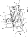
Fig. 1 is perspective view of a connector system in a pre-staged position in accordance with one embodiment; -
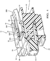
Fig. 2 is a cutaway view of the connector system ofFig. 1 in the pre-staged position in accordance with one embodiment; -
Fig.3 is a perspective view of the connector system ofFig. 1 in a staged position in accordance with one embodiment; and -
Fig. 4 is a cutaway view of the connector system ofFig. 1 in the staged position in accordance with one embodiment. - A connector system is presented herein. This connector system incorporates a lock-out feature that protects an operator from unintentionally moving the connector bodies of the connector system from a pre-staged position in which the connector bodies are mated but connector elements, such as electrical terminals, within the connector bodies are disconnected to staged position in which the connector elements are connected. In the pre-staged position, the two connector bodies are locked together so that cannot be disconnected from one another but cannot be moved to the staged position without simultaneously activating a lock-out feature while pushing the two connector bodies together.
- Such a connector system may be used as part of a high voltage interlock (HVIL) system that controls whether an associated high voltage circuit, e.g.an output of a battery pack in an electrical vehicle, is energized based on the connection state of the connector system. The connector system described herein addresses a problem of energizing the high voltage circuit due to inadvertent connection of the connector system that may pose causes a safety risk by adding a locking feature to the connection system that will not allow plug connector body to be moved from the pre-staged position to the staged position without activating the locking feature.
-
Figs. 1 through 4 illustrate a non-limiting example ofconnector system 10 having aplug connector body 12, asocket connector body 14 configured to mate with theplug connector body 12, and alocking feature 16 that is configured to secure theplug connector body 12 to thesocket connector body 14 in apre-staged position 18 shown inFigs. 1 and2 and further configured to secure theplug connector body 12 to thesocket connector body 14 in a stagedposition 20 shown inFigs. 3 and4 . Thesocket connector body 14 contains first and second female electrical terminals (not shown) that are connected to first and second wire cables (not shown) or other electrical conductors, e.g. bus bars or circuit board traces (not shown). Theplug connector body 12 contains a shunt terminal (not shown) having two male pins (not shown) configured to interface with the female terminals that are electrically connected (shunted) to one another. In the illustrated example, the shunt terminal is not connected to any wire cables or other electrical conductors outside of theplug connector body 12. - The
socket connector body 14 includes aterminal housing 22 defining terminal cavities (not shown) extending through theterminal housing 22 for receiving the first and second female terminals therein. Thesocket connector body 14 also has ashroud 24 that at least partially surrounds theterminal housing 22 and can be integrally or separately connected to theterminal housing 22 in any suitable manner. Theshroud 24 defines a socket for receiving the plug connector. - The
plug connector body 12 defines alock tab 26 that extends outwardly from theplug connector body 12 and has a leadingedge 26A and atrailing edge 26B designated relative to the direction of insertion of theplug connector body 12 into theshroud 24 of thesocket connector body 14. Thesocket connector body 14 includes a longitudinally extendinglock arm 28 pivotably attached to thesocket connector body 14. Afirst end 28A of thelock arm 28 defines alock nib 30 also having a leadingedge 30A and atrailing edge 30B, again designated relative to the direction of insertion of theplug connector body 12 into theshroud 24 of thesocket connector body 14. Thelock arm 28 is integrally connected to thesocket connector body 14 by aresilient U-shaped strap 32 that is configured to impose a hold-down force on thefirst end 28A of thelock arm 28 when thelock arm 28 is pivoted from a state of rest by pressing asecond end 28B of thelock arm 28 opposite thefirst end 28A. When thelock arm 28 is in the state of rest and theconnector system 10 is in thepre-staged position 18, the leadingedge 30A of thelock nib 30 will engage the leadingedge 26A of thelock tab 26. When thelock arm 28 is in the state of rest and theconnector system 10 is in the stagedposition 20, thetrailing edge 30B of thelock nib 30 will engage thetrailing edge 26B of thelock tab 26. - The leading
edge 26A of thelock tab 26 is substantially parallel to the leadingedge 30A of thelock nib 30. As used herein, substantially parallel means ± 10° of absolutely parallel. In the illustrated example, the leadingedge 26A of thelock tab 26 is substantially perpendicular to the surface of theplug connector body 12 from which it protrudes. As used herein, substantially perpendicular means ± 10° of absolutely perpendicular. The leadingedge 30A of thelock nib 30 is also substantially perpendicular to the top surface of thelock arm 28. The leadingedge 26A of thelock tab 26 is not angled away from the leadingedge 30A of thelock nib 30. In other words, it's free from being angled away. Also, the leadingedge 30A of thelock nib 30 is not angled toward the leadingedge 26A of thelock tab 26. In alternative embodiments, the leading edge of the lock tab may be angled toward the leading edge of the lock nib and the leading edge of the lock nib may be angled away from the leading edge of the lock tab. Without subscribing to any particular theory of operation, the leading edges in the configuration described above create a mechanical interference when the first and socket connector bodies are pushed from thepre-staged position 18 toward the stagedposition 20, thus preventing movement of theplug connector body 12 relative to thesocket connector body 14. - Similarly, the
trailing edge 26B of thelock tab 26 is substantially parallel to thetrailing edge 30B of thelock nib 30. In the illustrated example, the trailingedge 26B of thelock tab 26 is substantially perpendicular to the surface of theplug connector body 12 from which it protrudes. The trailingedge 30B of thelock nib 30 is also substantially perpendicular to the top surface of thelock arm 28. The trailingedge 26B of thelock tab 26 is not angled away from the trailingedge 30B of thelock nib 30. Also, the trailingedge 30B of thelock nib 30 is not angled toward the trailingedge 26B of thelock tab 26. In alternative embodiments, the trailing edge of the lock tab may be angled toward the trailing edge of the lock nib and the trailing edge of the lock nib may be angled away from the trailing edge of the lock tab. Without subscribing to any particular theory of operation, the trailing edges in the configuration described above create a mechanical interference when the first and socket connector bodies are pushed from the stagedposition 20 toward thepre-staged position 18, thus preventing movement of theplug connector body 12 relative to thesocket connector body 14. - To move the plug connector from the
pre-staged position 18 to the stagedposition 20 or from the stagedposition 20 to thepre-staged position 18, an operator (not shown) manually depresses thesecond end 28B of thelock arm 28, causing thefirst end 28A of thelock arm 28 to pivot upward and away from theplug connector body 12 so that thelock nib 30 no longer engages thelock tab 26. When thelock nib 30 is disengaged from thelock tab 26, theplug connector body 12 may be moved from thepre-staged position 18 to the stagedposition 20 or from the stagedposition 20 to thepre-staged position 18. - The
plug connector body 12 also defines a pair ofstops 34 projecting from the connector body having leadingedges 34A and trailingedges 34B, here again designated relative to the direction of insertion of theplug connector body 12 into theshroud 24 of thesocket connector body 14. When theplug connector body 12 is initially mated with thesocket connector body 14, the angled leadingedges 34A of thestops 34 raise theU-shaped strap 32 allowing thestops 34 to pass under theU-shaped strap 32. After thestops 34 pass under theU-shaped strap 32, theU-shaped strap 32 returns to its rest position. Engagement of the trailingedges 34B of thestops 34 inhibit removal of theplug connector body 12 from thesocket connector body 14 once mated and restrict further movement of theplug connector body 12 once it reaches thepre-staged position 18. Theleading edges 34A of thestops 34 are angled away from leadingedges 32A of theU-shaped strap 32 and trailingedges 34B of thestops 34 are substantially parallel to trailingedges 32B of theU-shaped strap 32. - As best shown in
Figs 1 and3 , theplug connector body 12 has a lock outfeature 36 that includes aplanar plug tab 38 extending from one side of theplug connector body 12. The lock outfeature 36 also includes at least one and preferably twoplanar socket tabs 40 extending from thesocket connector body 14 and arranged so that theplug tab 38 can slide between thesocket tabs 40 as theplug connector body 12 is moved from thepre-staged position 18 to the stagedposition 20. Thesocket tabs 40 define a pair ofapertures 42 aligned with one another that are configured to accept a lock out pin (not shown) that may be in the form of a screwdriver shaft or hasp of a padlock. When the lock out pin is inserted within theapertures 42, theplug tab 38 is inhibited from sliding between thesocket tabs 40, thereby preventing the plug connector from being moved from the pre-staged position18 to the stagedposition 20. This can serve as a secondary means of preventing adverting movement of the plug connector to the stagedposition 20. Theplug tab 38 may also includegraphics 44 to indicate the status of the connector position of the circuit to which theconnector system 10 is connected. - The
connector system 10 may further include a connector position assurance device (not shown) that is configured to prevent inadvertent activation of thelock arm 28. - Accordingly, a
connector system 10 is provided. Theconnector system 10 provides the benefits of alocking feature 16 may be built into the connection system utilizing the primary connector latch portion of the design. There may be a series of lock and latches on the first and socket connector bodies that work together to provide thelocking feature 16. Theconnector system 10 allows the connection to be unmated from the stagedposition 20 to thepre-staged position 18 multiple times. In thepre-staged position 18, theconnector system 10 is locked in a position that does not allow electrical continuity to continue. Theconnector system 10 remains locked in itspre-staged position 18 until the operator needs to reconnect theconnector system 10. At that time, the lockingfeature 16 would again need to be activated to allow theconnector system 10 to return to the stagedposition 20. - While the illustrated example only includes electrical terminals connected to wire cables in the socket connector, other embodiments may be envisioned in which only the plug connector includes electrical terminals connected to wire cables or both the plug and socket connectors include electrical terminals connected to wire cables
- The examples presented herein are directed to electrical connector systems. However, other embodiments of the connector system may be envisioned that are adapted for use with optical cables or hybrid connections including both electrical and optical cables. Yet other embodiments of the connector system may be envisioned that are configured for connecting pneumatic or hydraulic lines.
- While this invention has been described in terms of the preferred embodiments thereof, it is not intended to be so limited, but rather only to the extent set forth in the claims that follow. Moreover, the use of the terms first, second, upper, lower, etc. does not denote any order of importance or orientation, but rather the terms first, second, upper, lower, etc. are used to distinguish one element from another. Furthermore, the use of the terms a, an, etc. do not denote a limitation of quantity, but rather denote the presence of at least one of the referenced items.
Claims (9)
- An electrical connector system (10), comprising:a first connector body (12) containing a first plurality of terminals;a second connector body (14) containing a second plurality of terminals configured to interconnect with the first plurality of terminals, said second connector body (14) configured to receive the first connector body (12); anda locking feature (16) configured to secure the first connector body (12) to the second connector body (14) in a pre-staged position (18) in which the first plurality of terminals is not connected to the second plurality of terminals and further configured to secure the first connector body (12) to the second connector body (14) in a staged position (20) in which the first plurality of terminals is connected to the second plurality of terminals after disengaging the locking feature (16) in the pre-staged position (18).
- The electrical connector system (10) according to claim 1, wherein the locking feature (16) comprises:a latch (30) defined by the first connector body (12) having a leading edge (30A) and a trailing edge (30B); anda flexible lock arm (28) pivotably attached to the second connector body (14) by a resilient U-shaped strap (32), said lock arm (28) configured to engage the leading edge (30A) of the latch (30), thereby securing the first connector body (12) in the pre-staged position (18) and further configured to engage the trailing edge (30B) of the latch (30) after disengaging the lock arm (28) from the latch (30) in the pre-staged condition, thereby securing the first connector body (12) in the staged position (20).
- The electrical connector system (10) according to claim 2, wherein the leading edge (30A) of the latch (30) is not angled away from the lock arm (28).
- The electrical connector system (10) according to claim 2, wherein the locking feature (16) further comprises a stop (26) defined by the first connector body (12) and configured to engage the U-shaped strap (32), thereby inhibiting removal of the first connector body (12) from the second connector body (14).
- The electrical connector system (10) according to one of the preceding claims, wherein the second connector body (14) contains first and second electrical terminals attached to first and second wire cables respectively, wherein the first connector body (12) contains a shunt connector configured to interconnect the first and second electrical terminals when the first and second connector bodies are in the staged position (20) and wherein the shunt connector is configured to disconnect the first electrical terminal from the second electrical terminal when the first and second connector bodies are in the pre-staged position (18).
- The electrical connector system (10) according to claim 5, wherein the first and second wire cables are connected to a high voltage interlock (HVIL) system.
- The electrical connector system (10) according to one of the preceding claims, wherein the electrical connector system (10) further includes a lock out feature (36) configured to prevent the first connector body (12) from being moved from the pre-staged position (18) to the staged position (20) regardless of the locking feature (16).
- The electrical connector system (10) according to claim 7, wherein the lock out feature (36) includes a solid planar tab (38) extending from the first connector body (12) and a pair of perforated planar tabs (40) extending from the second connector body (14) each defining an aperture (42) aligned with one another, wherein the perforated planar tabs (40) are arranged so that the solid planar tab (38) can slide between the pair of perforated planar tabs (40) as the first connector body (12) is moved from the pre-staged to the staged position (20).
- The electrical connector system (10) according to claim 8, wherein an object inserted within the aperture (42) will block the solid planar tab (38) from sliding between the perforated planar tabs (40), thereby inhibiting the first connector body (12) from being moved from the pre-staged position (18) to the staged position (20).
Applications Claiming Priority (2)
| Application Number | Priority Date | Filing Date | Title |
|---|---|---|---|
| US201662339135P | 2016-05-20 | 2016-05-20 | |
| US15/499,491 US9929508B2 (en) | 2016-05-20 | 2017-04-27 | Electrical connector |
Publications (2)
| Publication Number | Publication Date |
|---|---|
| EP3247003A1 true EP3247003A1 (en) | 2017-11-22 |
| EP3247003B1 EP3247003B1 (en) | 2020-08-05 |
Family
ID=58738962
Family Applications (1)
| Application Number | Title | Priority Date | Filing Date |
|---|---|---|---|
| EP17171965.1A Active EP3247003B1 (en) | 2016-05-20 | 2017-05-19 | Electrical connector |
Country Status (2)
| Country | Link |
|---|---|
| US (1) | US9929508B2 (en) |
| EP (1) | EP3247003B1 (en) |
Families Citing this family (4)
| Publication number | Priority date | Publication date | Assignee | Title |
|---|---|---|---|---|
| JP6944331B2 (en) * | 2017-05-18 | 2021-10-06 | モレックス エルエルシー | Connector and connector assembly. |
| CN209561752U (en) * | 2018-08-17 | 2019-10-29 | 连展科技电子(昆山)有限公司 | Automotive coupler electric connector and automobile-used electric connector for socket |
| JP2022123930A (en) * | 2021-02-15 | 2022-08-25 | 株式会社オートネットワーク技術研究所 | connector |
| US11605912B2 (en) * | 2021-06-08 | 2023-03-14 | Dinkle Enterprise Co., Ltd. | Terminal block for connecting a circuit board and wires with a slidable fastener on the body |
Citations (4)
| Publication number | Priority date | Publication date | Assignee | Title |
|---|---|---|---|---|
| FR2756669A1 (en) * | 1996-12-02 | 1998-06-05 | Marechal Sepm | Lockable Open Position for electrical Connector |
| EP0848456A2 (en) * | 1996-12-13 | 1998-06-17 | General Motors Corporation | Electrical connector with locking connector position assurance member |
| WO2010068293A1 (en) * | 2008-12-12 | 2010-06-17 | Tyco Electronics Corporation | Connector assembly with two stage latch |
| EP2482390A2 (en) * | 2011-02-01 | 2012-08-01 | Delphi Technologies, Inc. | Electrical connection system including connector body with integral primary and secondary latch |
Family Cites Families (5)
| Publication number | Priority date | Publication date | Assignee | Title |
|---|---|---|---|---|
| US4621885A (en) * | 1985-09-20 | 1986-11-11 | Amp Incorporated | Ribbon cable connector with improved cover latch |
| FR2759205B1 (en) * | 1997-02-06 | 1999-04-30 | Air Lb International Sa | ELECTRICAL CONNECTION DEVICE WITH IMPROVED CONTACT SECURITY |
| US5934926A (en) * | 1998-02-06 | 1999-08-10 | Packard Hughes Interconnect Company | Electrical connector system with pre-staged feature |
| US7503793B2 (en) | 2007-01-18 | 2009-03-17 | Delphi Technologies, Inc. | Electrical connector body having a transverse hold-down beam for a shroud-integrated lock arm |
| US7549887B1 (en) * | 2008-04-29 | 2009-06-23 | Yazaki North America, Inc. | Connector |
-
2017
- 2017-04-27 US US15/499,491 patent/US9929508B2/en active Active
- 2017-05-19 EP EP17171965.1A patent/EP3247003B1/en active Active
Patent Citations (4)
| Publication number | Priority date | Publication date | Assignee | Title |
|---|---|---|---|---|
| FR2756669A1 (en) * | 1996-12-02 | 1998-06-05 | Marechal Sepm | Lockable Open Position for electrical Connector |
| EP0848456A2 (en) * | 1996-12-13 | 1998-06-17 | General Motors Corporation | Electrical connector with locking connector position assurance member |
| WO2010068293A1 (en) * | 2008-12-12 | 2010-06-17 | Tyco Electronics Corporation | Connector assembly with two stage latch |
| EP2482390A2 (en) * | 2011-02-01 | 2012-08-01 | Delphi Technologies, Inc. | Electrical connection system including connector body with integral primary and secondary latch |
Also Published As
| Publication number | Publication date |
|---|---|
| EP3247003B1 (en) | 2020-08-05 |
| US9929508B2 (en) | 2018-03-27 |
| US20170338593A1 (en) | 2017-11-23 |
Similar Documents
| Publication | Publication Date | Title |
|---|---|---|
| EP3247003B1 (en) | Electrical connector | |
| CN106532332B (en) | Right-angle connector with terminal contact protection | |
| US6648669B1 (en) | Electrical connection with sequential disconnect | |
| US7232324B2 (en) | Electrical connector bridge arrangement with release means | |
| EP3416247A1 (en) | Connector system with low profile connector position assurance device | |
| US9225116B2 (en) | Quick connect power connector isolating system | |
| US9455523B1 (en) | Right angle connection assembly | |
| US9774125B2 (en) | Connector having a moving plate | |
| EP2993740A1 (en) | Connector with connector position assurance device | |
| US9705228B2 (en) | Connector system with disconnection evident connector position assurance feature | |
| CN110571567B (en) | Staged release electrical connector assembly | |
| EP3540873B1 (en) | Connector and socket | |
| US20100317214A1 (en) | Electrical connector system with power and command connectors | |
| CN112262505B (en) | Modular plug connector system | |
| CN112262506B (en) | Fixing system for plug connectors | |
| US20180323538A1 (en) | Electrical connector with retractable terminal-stabilizer | |
| CN104145378A (en) | Plug connector | |
| EP3706254A1 (en) | High voltage electrical connector with cpa assembled on slider | |
| KR101870886B1 (en) | Plug-type connection apparatus | |
| CN107404041B (en) | Electrical connector | |
| EP2937949B1 (en) | Connector for motor vehicles and process for mounting of this connector | |
| JP7408279B2 (en) | power distribution assembly | |
| EP2854231B1 (en) | Plug and socket device | |
| EP3300179B1 (en) | Electrical connector with male blade stabilizer | |
| US9814146B2 (en) | Drive apparatus |
Legal Events
| Date | Code | Title | Description |
|---|---|---|---|
| PUAI | Public reference made under article 153(3) epc to a published international application that has entered the european phase |
Free format text: ORIGINAL CODE: 0009012 |
|
| STAA | Information on the status of an ep patent application or granted ep patent |
Free format text: STATUS: THE APPLICATION HAS BEEN PUBLISHED |
|
| AK | Designated contracting states |
Kind code of ref document: A1 Designated state(s): AL AT BE BG CH CY CZ DE DK EE ES FI FR GB GR HR HU IE IS IT LI LT LU LV MC MK MT NL NO PL PT RO RS SE SI SK SM TR |
|
| AX | Request for extension of the european patent |
Extension state: BA ME |
|
| STAA | Information on the status of an ep patent application or granted ep patent |
Free format text: STATUS: REQUEST FOR EXAMINATION WAS MADE |
|
| 17P | Request for examination filed |
Effective date: 20180522 |
|
| RBV | Designated contracting states (corrected) |
Designated state(s): AL AT BE BG CH CY CZ DE DK EE ES FI FR GB GR HR HU IE IS IT LI LT LU LV MC MK MT NL NO PL PT RO RS SE SI SK SM TR |
|
| RAP1 | Party data changed (applicant data changed or rights of an application transferred) |
Owner name: APTIV TECHNOLOGIES LIMITED |
|
| GRAP | Despatch of communication of intention to grant a patent |
Free format text: ORIGINAL CODE: EPIDOSNIGR1 |
|
| STAA | Information on the status of an ep patent application or granted ep patent |
Free format text: STATUS: GRANT OF PATENT IS INTENDED |
|
| RIC1 | Information provided on ipc code assigned before grant |
Ipc: H01R 13/627 20060101AFI20200214BHEP Ipc: H01R 13/639 20060101ALN20200214BHEP |
|
| RIC1 | Information provided on ipc code assigned before grant |
Ipc: H01R 13/639 20060101ALN20200225BHEP Ipc: H01R 13/627 20060101AFI20200225BHEP |
|
| INTG | Intention to grant announced |
Effective date: 20200316 |
|
| GRAS | Grant fee paid |
Free format text: ORIGINAL CODE: EPIDOSNIGR3 |
|
| GRAA | (expected) grant |
Free format text: ORIGINAL CODE: 0009210 |
|
| STAA | Information on the status of an ep patent application or granted ep patent |
Free format text: STATUS: THE PATENT HAS BEEN GRANTED |
|
| AK | Designated contracting states |
Kind code of ref document: B1 Designated state(s): AL AT BE BG CH CY CZ DE DK EE ES FI FR GB GR HR HU IE IS IT LI LT LU LV MC MK MT NL NO PL PT RO RS SE SI SK SM TR |
|
| REG | Reference to a national code |
Ref country code: GB Ref legal event code: FG4D |
|
| REG | Reference to a national code |
Ref country code: CH Ref legal event code: EP |
|
| REG | Reference to a national code |
Ref country code: AT Ref legal event code: REF Ref document number: 1300038 Country of ref document: AT Kind code of ref document: T Effective date: 20200815 |
|
| REG | Reference to a national code |
Ref country code: DE Ref legal event code: R096 Ref document number: 602017020859 Country of ref document: DE |
|
| REG | Reference to a national code |
Ref country code: IE Ref legal event code: FG4D |
|
| REG | Reference to a national code |
Ref country code: LT Ref legal event code: MG4D |
|
| REG | Reference to a national code |
Ref country code: NL Ref legal event code: MP Effective date: 20200805 |
|
| REG | Reference to a national code |
Ref country code: AT Ref legal event code: MK05 Ref document number: 1300038 Country of ref document: AT Kind code of ref document: T Effective date: 20200805 |
|
| PG25 | Lapsed in a contracting state [announced via postgrant information from national office to epo] |
Ref country code: NO Free format text: LAPSE BECAUSE OF FAILURE TO SUBMIT A TRANSLATION OF THE DESCRIPTION OR TO PAY THE FEE WITHIN THE PRESCRIBED TIME-LIMIT Effective date: 20201105 Ref country code: BG Free format text: LAPSE BECAUSE OF FAILURE TO SUBMIT A TRANSLATION OF THE DESCRIPTION OR TO PAY THE FEE WITHIN THE PRESCRIBED TIME-LIMIT Effective date: 20201105 Ref country code: SE Free format text: LAPSE BECAUSE OF FAILURE TO SUBMIT A TRANSLATION OF THE DESCRIPTION OR TO PAY THE FEE WITHIN THE PRESCRIBED TIME-LIMIT Effective date: 20200805 Ref country code: AT Free format text: LAPSE BECAUSE OF FAILURE TO SUBMIT A TRANSLATION OF THE DESCRIPTION OR TO PAY THE FEE WITHIN THE PRESCRIBED TIME-LIMIT Effective date: 20200805 Ref country code: LT Free format text: LAPSE BECAUSE OF FAILURE TO SUBMIT A TRANSLATION OF THE DESCRIPTION OR TO PAY THE FEE WITHIN THE PRESCRIBED TIME-LIMIT Effective date: 20200805 Ref country code: HR Free format text: LAPSE BECAUSE OF FAILURE TO SUBMIT A TRANSLATION OF THE DESCRIPTION OR TO PAY THE FEE WITHIN THE PRESCRIBED TIME-LIMIT Effective date: 20200805 Ref country code: PT Free format text: LAPSE BECAUSE OF FAILURE TO SUBMIT A TRANSLATION OF THE DESCRIPTION OR TO PAY THE FEE WITHIN THE PRESCRIBED TIME-LIMIT Effective date: 20201207 Ref country code: ES Free format text: LAPSE BECAUSE OF FAILURE TO SUBMIT A TRANSLATION OF THE DESCRIPTION OR TO PAY THE FEE WITHIN THE PRESCRIBED TIME-LIMIT Effective date: 20200805 Ref country code: FI Free format text: LAPSE BECAUSE OF FAILURE TO SUBMIT A TRANSLATION OF THE DESCRIPTION OR TO PAY THE FEE WITHIN THE PRESCRIBED TIME-LIMIT Effective date: 20200805 Ref country code: GR Free format text: LAPSE BECAUSE OF FAILURE TO SUBMIT A TRANSLATION OF THE DESCRIPTION OR TO PAY THE FEE WITHIN THE PRESCRIBED TIME-LIMIT Effective date: 20201106 |
|
| PG25 | Lapsed in a contracting state [announced via postgrant information from national office to epo] |
Ref country code: LV Free format text: LAPSE BECAUSE OF FAILURE TO SUBMIT A TRANSLATION OF THE DESCRIPTION OR TO PAY THE FEE WITHIN THE PRESCRIBED TIME-LIMIT Effective date: 20200805 Ref country code: NL Free format text: LAPSE BECAUSE OF FAILURE TO SUBMIT A TRANSLATION OF THE DESCRIPTION OR TO PAY THE FEE WITHIN THE PRESCRIBED TIME-LIMIT Effective date: 20200805 Ref country code: RS Free format text: LAPSE BECAUSE OF FAILURE TO SUBMIT A TRANSLATION OF THE DESCRIPTION OR TO PAY THE FEE WITHIN THE PRESCRIBED TIME-LIMIT Effective date: 20200805 Ref country code: PL Free format text: LAPSE BECAUSE OF FAILURE TO SUBMIT A TRANSLATION OF THE DESCRIPTION OR TO PAY THE FEE WITHIN THE PRESCRIBED TIME-LIMIT Effective date: 20200805 Ref country code: IS Free format text: LAPSE BECAUSE OF FAILURE TO SUBMIT A TRANSLATION OF THE DESCRIPTION OR TO PAY THE FEE WITHIN THE PRESCRIBED TIME-LIMIT Effective date: 20201205 |
|
| PG25 | Lapsed in a contracting state [announced via postgrant information from national office to epo] |
Ref country code: SM Free format text: LAPSE BECAUSE OF FAILURE TO SUBMIT A TRANSLATION OF THE DESCRIPTION OR TO PAY THE FEE WITHIN THE PRESCRIBED TIME-LIMIT Effective date: 20200805 Ref country code: EE Free format text: LAPSE BECAUSE OF FAILURE TO SUBMIT A TRANSLATION OF THE DESCRIPTION OR TO PAY THE FEE WITHIN THE PRESCRIBED TIME-LIMIT Effective date: 20200805 Ref country code: RO Free format text: LAPSE BECAUSE OF FAILURE TO SUBMIT A TRANSLATION OF THE DESCRIPTION OR TO PAY THE FEE WITHIN THE PRESCRIBED TIME-LIMIT Effective date: 20200805 Ref country code: CZ Free format text: LAPSE BECAUSE OF FAILURE TO SUBMIT A TRANSLATION OF THE DESCRIPTION OR TO PAY THE FEE WITHIN THE PRESCRIBED TIME-LIMIT Effective date: 20200805 Ref country code: DK Free format text: LAPSE BECAUSE OF FAILURE TO SUBMIT A TRANSLATION OF THE DESCRIPTION OR TO PAY THE FEE WITHIN THE PRESCRIBED TIME-LIMIT Effective date: 20200805 |
|
| REG | Reference to a national code |
Ref country code: DE Ref legal event code: R097 Ref document number: 602017020859 Country of ref document: DE |
|
| PG25 | Lapsed in a contracting state [announced via postgrant information from national office to epo] |
Ref country code: AL Free format text: LAPSE BECAUSE OF FAILURE TO SUBMIT A TRANSLATION OF THE DESCRIPTION OR TO PAY THE FEE WITHIN THE PRESCRIBED TIME-LIMIT Effective date: 20200805 |
|
| PLBE | No opposition filed within time limit |
Free format text: ORIGINAL CODE: 0009261 |
|
| STAA | Information on the status of an ep patent application or granted ep patent |
Free format text: STATUS: NO OPPOSITION FILED WITHIN TIME LIMIT |
|
| PG25 | Lapsed in a contracting state [announced via postgrant information from national office to epo] |
Ref country code: SK Free format text: LAPSE BECAUSE OF FAILURE TO SUBMIT A TRANSLATION OF THE DESCRIPTION OR TO PAY THE FEE WITHIN THE PRESCRIBED TIME-LIMIT Effective date: 20200805 |
|
| 26N | No opposition filed |
Effective date: 20210507 |
|
| PG25 | Lapsed in a contracting state [announced via postgrant information from national office to epo] |
Ref country code: IT Free format text: LAPSE BECAUSE OF FAILURE TO SUBMIT A TRANSLATION OF THE DESCRIPTION OR TO PAY THE FEE WITHIN THE PRESCRIBED TIME-LIMIT Effective date: 20200805 |
|
| PG25 | Lapsed in a contracting state [announced via postgrant information from national office to epo] |
Ref country code: SI Free format text: LAPSE BECAUSE OF FAILURE TO SUBMIT A TRANSLATION OF THE DESCRIPTION OR TO PAY THE FEE WITHIN THE PRESCRIBED TIME-LIMIT Effective date: 20200805 |
|
| REG | Reference to a national code |
Ref country code: CH Ref legal event code: PL |
|
| PG25 | Lapsed in a contracting state [announced via postgrant information from national office to epo] |
Ref country code: CH Free format text: LAPSE BECAUSE OF NON-PAYMENT OF DUE FEES Effective date: 20210531 Ref country code: LU Free format text: LAPSE BECAUSE OF NON-PAYMENT OF DUE FEES Effective date: 20210519 Ref country code: MC Free format text: LAPSE BECAUSE OF FAILURE TO SUBMIT A TRANSLATION OF THE DESCRIPTION OR TO PAY THE FEE WITHIN THE PRESCRIBED TIME-LIMIT Effective date: 20200805 Ref country code: LI Free format text: LAPSE BECAUSE OF NON-PAYMENT OF DUE FEES Effective date: 20210531 |
|
| REG | Reference to a national code |
Ref country code: BE Ref legal event code: MM Effective date: 20210531 |
|
| PG25 | Lapsed in a contracting state [announced via postgrant information from national office to epo] |
Ref country code: IE Free format text: LAPSE BECAUSE OF NON-PAYMENT OF DUE FEES Effective date: 20210519 |
|
| PG25 | Lapsed in a contracting state [announced via postgrant information from national office to epo] |
Ref country code: BE Free format text: LAPSE BECAUSE OF NON-PAYMENT OF DUE FEES Effective date: 20210531 |
|
| PG25 | Lapsed in a contracting state [announced via postgrant information from national office to epo] |
Ref country code: HU Free format text: LAPSE BECAUSE OF FAILURE TO SUBMIT A TRANSLATION OF THE DESCRIPTION OR TO PAY THE FEE WITHIN THE PRESCRIBED TIME-LIMIT; INVALID AB INITIO Effective date: 20170519 |
|
| P01 | Opt-out of the competence of the unified patent court (upc) registered |
Effective date: 20230420 |
|
| PG25 | Lapsed in a contracting state [announced via postgrant information from national office to epo] |
Ref country code: CY Free format text: LAPSE BECAUSE OF FAILURE TO SUBMIT A TRANSLATION OF THE DESCRIPTION OR TO PAY THE FEE WITHIN THE PRESCRIBED TIME-LIMIT Effective date: 20200805 |
|
| PGFP | Annual fee paid to national office [announced via postgrant information from national office to epo] |
Ref country code: FR Payment date: 20230525 Year of fee payment: 7 Ref country code: DE Payment date: 20230517 Year of fee payment: 7 |
|
| PGFP | Annual fee paid to national office [announced via postgrant information from national office to epo] |
Ref country code: GB Payment date: 20230522 Year of fee payment: 7 |
|
| PG25 | Lapsed in a contracting state [announced via postgrant information from national office to epo] |
Ref country code: MK Free format text: LAPSE BECAUSE OF FAILURE TO SUBMIT A TRANSLATION OF THE DESCRIPTION OR TO PAY THE FEE WITHIN THE PRESCRIBED TIME-LIMIT Effective date: 20200805 |