EP3246997A1 - Electrical connector system - Google Patents
Electrical connector system Download PDFInfo
- Publication number
- EP3246997A1 EP3246997A1 EP17163936.2A EP17163936A EP3246997A1 EP 3246997 A1 EP3246997 A1 EP 3246997A1 EP 17163936 A EP17163936 A EP 17163936A EP 3246997 A1 EP3246997 A1 EP 3246997A1
- Authority
- EP
- European Patent Office
- Prior art keywords
- blade
- terminal
- male
- shoulder
- defines
- Prior art date
- Legal status (The legal status is an assumption and is not a legal conclusion. Google has not performed a legal analysis and makes no representation as to the accuracy of the status listed.)
- Granted
Links
- 230000007704 transition Effects 0.000 claims description 16
- 230000013011 mating Effects 0.000 claims description 2
- 239000004020 conductor Substances 0.000 description 23
- 239000000463 material Substances 0.000 description 6
- 229920001707 polybutylene terephthalate Polymers 0.000 description 6
- 239000011521 glass Substances 0.000 description 5
- 239000000356 contaminant Substances 0.000 description 3
- 238000009413 insulation Methods 0.000 description 3
- 238000000034 method Methods 0.000 description 3
- PXHVJJICTQNCMI-UHFFFAOYSA-N Nickel Chemical compound [Ni] PXHVJJICTQNCMI-UHFFFAOYSA-N 0.000 description 2
- 238000010586 diagram Methods 0.000 description 2
- 239000013536 elastomeric material Substances 0.000 description 2
- 230000002401 inhibitory effect Effects 0.000 description 2
- 238000007747 plating Methods 0.000 description 2
- 229910000881 Cu alloy Inorganic materials 0.000 description 1
- BQCADISMDOOEFD-UHFFFAOYSA-N Silver Chemical compound [Ag] BQCADISMDOOEFD-UHFFFAOYSA-N 0.000 description 1
- 238000013459 approach Methods 0.000 description 1
- 230000005540 biological transmission Effects 0.000 description 1
- 150000001875 compounds Chemical class 0.000 description 1
- 238000011109 contamination Methods 0.000 description 1
- 238000005260 corrosion Methods 0.000 description 1
- 230000007797 corrosion Effects 0.000 description 1
- 230000007613 environmental effect Effects 0.000 description 1
- 239000011888 foil Substances 0.000 description 1
- 239000011810 insulating material Substances 0.000 description 1
- 238000002955 isolation Methods 0.000 description 1
- 239000002184 metal Substances 0.000 description 1
- 229910052751 metal Inorganic materials 0.000 description 1
- 239000011104 metalized film Substances 0.000 description 1
- 229910052759 nickel Inorganic materials 0.000 description 1
- 238000004806 packaging method and process Methods 0.000 description 1
- -1 polybutylene terephthalate Polymers 0.000 description 1
- 229920000728 polyester Polymers 0.000 description 1
- 229910052709 silver Inorganic materials 0.000 description 1
- 239000004332 silver Substances 0.000 description 1
Images


Classifications
-
- H—ELECTRICITY
- H01—ELECTRIC ELEMENTS
- H01R—ELECTRICALLY-CONDUCTIVE CONNECTIONS; STRUCTURAL ASSOCIATIONS OF A PLURALITY OF MUTUALLY-INSULATED ELECTRICAL CONNECTING ELEMENTS; COUPLING DEVICES; CURRENT COLLECTORS
- H01R13/00—Details of coupling devices of the kinds covered by groups H01R12/70 or H01R24/00 - H01R33/00
- H01R13/648—Protective earth or shield arrangements on coupling devices, e.g. anti-static shielding
- H01R13/658—High frequency shielding arrangements, e.g. against EMI [Electro-Magnetic Interference] or EMP [Electro-Magnetic Pulse]
- H01R13/6581—Shield structure
-
- H—ELECTRICITY
- H01—ELECTRIC ELEMENTS
- H01R—ELECTRICALLY-CONDUCTIVE CONNECTIONS; STRUCTURAL ASSOCIATIONS OF A PLURALITY OF MUTUALLY-INSULATED ELECTRICAL CONNECTING ELEMENTS; COUPLING DEVICES; CURRENT COLLECTORS
- H01R11/00—Individual connecting elements providing two or more spaced connecting locations for conductive members which are, or may be, thereby interconnected, e.g. end pieces for wires or cables supported by the wire or cable and having means for facilitating electrical connection to some other wire, terminal, or conductive member, blocks of binding posts
- H01R11/03—Individual connecting elements providing two or more spaced connecting locations for conductive members which are, or may be, thereby interconnected, e.g. end pieces for wires or cables supported by the wire or cable and having means for facilitating electrical connection to some other wire, terminal, or conductive member, blocks of binding posts characterised by the relationship between the connecting locations
- H01R11/07—Individual connecting elements providing two or more spaced connecting locations for conductive members which are, or may be, thereby interconnected, e.g. end pieces for wires or cables supported by the wire or cable and having means for facilitating electrical connection to some other wire, terminal, or conductive member, blocks of binding posts characterised by the relationship between the connecting locations the connecting locations being of the same type but different sizes
-
- H—ELECTRICITY
- H01—ELECTRIC ELEMENTS
- H01R—ELECTRICALLY-CONDUCTIVE CONNECTIONS; STRUCTURAL ASSOCIATIONS OF A PLURALITY OF MUTUALLY-INSULATED ELECTRICAL CONNECTING ELEMENTS; COUPLING DEVICES; CURRENT COLLECTORS
- H01R13/00—Details of coupling devices of the kinds covered by groups H01R12/70 or H01R24/00 - H01R33/00
- H01R13/02—Contact members
-
- H—ELECTRICITY
- H01—ELECTRIC ELEMENTS
- H01R—ELECTRICALLY-CONDUCTIVE CONNECTIONS; STRUCTURAL ASSOCIATIONS OF A PLURALITY OF MUTUALLY-INSULATED ELECTRICAL CONNECTING ELEMENTS; COUPLING DEVICES; CURRENT COLLECTORS
- H01R24/00—Two-part coupling devices, or either of their cooperating parts, characterised by their overall structure
- H01R24/38—Two-part coupling devices, or either of their cooperating parts, characterised by their overall structure having concentrically or coaxially arranged contacts
-
- H—ELECTRICITY
- H01—ELECTRIC ELEMENTS
- H01R—ELECTRICALLY-CONDUCTIVE CONNECTIONS; STRUCTURAL ASSOCIATIONS OF A PLURALITY OF MUTUALLY-INSULATED ELECTRICAL CONNECTING ELEMENTS; COUPLING DEVICES; CURRENT COLLECTORS
- H01R13/00—Details of coupling devices of the kinds covered by groups H01R12/70 or H01R24/00 - H01R33/00
- H01R13/02—Contact members
- H01R13/04—Pins or blades for co-operation with sockets
-
- H—ELECTRICITY
- H01—ELECTRIC ELEMENTS
- H01R—ELECTRICALLY-CONDUCTIVE CONNECTIONS; STRUCTURAL ASSOCIATIONS OF A PLURALITY OF MUTUALLY-INSULATED ELECTRICAL CONNECTING ELEMENTS; COUPLING DEVICES; CURRENT COLLECTORS
- H01R13/00—Details of coupling devices of the kinds covered by groups H01R12/70 or H01R24/00 - H01R33/00
- H01R13/02—Contact members
- H01R13/22—Contacts for co-operating by abutting
-
- H—ELECTRICITY
- H01—ELECTRIC ELEMENTS
- H01R—ELECTRICALLY-CONDUCTIVE CONNECTIONS; STRUCTURAL ASSOCIATIONS OF A PLURALITY OF MUTUALLY-INSULATED ELECTRICAL CONNECTING ELEMENTS; COUPLING DEVICES; CURRENT COLLECTORS
- H01R13/00—Details of coupling devices of the kinds covered by groups H01R12/70 or H01R24/00 - H01R33/00
- H01R13/40—Securing contact members in or to a base or case; Insulating of contact members
- H01R13/405—Securing in non-demountable manner, e.g. moulding, riveting
- H01R13/41—Securing in non-demountable manner, e.g. moulding, riveting by frictional grip in grommet, panel or base
-
- H—ELECTRICITY
- H01—ELECTRIC ELEMENTS
- H01R—ELECTRICALLY-CONDUCTIVE CONNECTIONS; STRUCTURAL ASSOCIATIONS OF A PLURALITY OF MUTUALLY-INSULATED ELECTRICAL CONNECTING ELEMENTS; COUPLING DEVICES; CURRENT COLLECTORS
- H01R13/00—Details of coupling devices of the kinds covered by groups H01R12/70 or H01R24/00 - H01R33/00
- H01R13/40—Securing contact members in or to a base or case; Insulating of contact members
- H01R13/42—Securing in a demountable manner
- H01R13/422—Securing in resilient one-piece base or case, e.g. by friction; One-piece base or case formed with resilient locking means
-
- H—ELECTRICITY
- H01—ELECTRIC ELEMENTS
- H01R—ELECTRICALLY-CONDUCTIVE CONNECTIONS; STRUCTURAL ASSOCIATIONS OF A PLURALITY OF MUTUALLY-INSULATED ELECTRICAL CONNECTING ELEMENTS; COUPLING DEVICES; CURRENT COLLECTORS
- H01R13/00—Details of coupling devices of the kinds covered by groups H01R12/70 or H01R24/00 - H01R33/00
- H01R13/648—Protective earth or shield arrangements on coupling devices, e.g. anti-static shielding
- H01R13/658—High frequency shielding arrangements, e.g. against EMI [Electro-Magnetic Interference] or EMP [Electro-Magnetic Pulse]
-
- H—ELECTRICITY
- H01—ELECTRIC ELEMENTS
- H01R—ELECTRICALLY-CONDUCTIVE CONNECTIONS; STRUCTURAL ASSOCIATIONS OF A PLURALITY OF MUTUALLY-INSULATED ELECTRICAL CONNECTING ELEMENTS; COUPLING DEVICES; CURRENT COLLECTORS
- H01R24/00—Two-part coupling devices, or either of their cooperating parts, characterised by their overall structure
-
- H—ELECTRICITY
- H01—ELECTRIC ELEMENTS
- H01R—ELECTRICALLY-CONDUCTIVE CONNECTIONS; STRUCTURAL ASSOCIATIONS OF A PLURALITY OF MUTUALLY-INSULATED ELECTRICAL CONNECTING ELEMENTS; COUPLING DEVICES; CURRENT COLLECTORS
- H01R31/00—Coupling parts supported only by co-operation with counterpart
- H01R31/02—Intermediate parts for distributing energy to two or more circuits in parallel, e.g. splitter
-
- H—ELECTRICITY
- H01—ELECTRIC ELEMENTS
- H01R—ELECTRICALLY-CONDUCTIVE CONNECTIONS; STRUCTURAL ASSOCIATIONS OF A PLURALITY OF MUTUALLY-INSULATED ELECTRICAL CONNECTING ELEMENTS; COUPLING DEVICES; CURRENT COLLECTORS
- H01R4/00—Electrically-conductive connections between two or more conductive members in direct contact, i.e. touching one another; Means for effecting or maintaining such contact; Electrically-conductive connections having two or more spaced connecting locations for conductors and using contact members penetrating insulation
- H01R4/10—Electrically-conductive connections between two or more conductive members in direct contact, i.e. touching one another; Means for effecting or maintaining such contact; Electrically-conductive connections having two or more spaced connecting locations for conductors and using contact members penetrating insulation effected solely by twisting, wrapping, bending, crimping, or other permanent deformation
- H01R4/18—Electrically-conductive connections between two or more conductive members in direct contact, i.e. touching one another; Means for effecting or maintaining such contact; Electrically-conductive connections having two or more spaced connecting locations for conductors and using contact members penetrating insulation effected solely by twisting, wrapping, bending, crimping, or other permanent deformation by crimping
- H01R4/183—Electrically-conductive connections between two or more conductive members in direct contact, i.e. touching one another; Means for effecting or maintaining such contact; Electrically-conductive connections having two or more spaced connecting locations for conductors and using contact members penetrating insulation effected solely by twisting, wrapping, bending, crimping, or other permanent deformation by crimping for cylindrical elongated bodies, e.g. cables having circular cross-section
-
- H—ELECTRICITY
- H01—ELECTRIC ELEMENTS
- H01R—ELECTRICALLY-CONDUCTIVE CONNECTIONS; STRUCTURAL ASSOCIATIONS OF A PLURALITY OF MUTUALLY-INSULATED ELECTRICAL CONNECTING ELEMENTS; COUPLING DEVICES; CURRENT COLLECTORS
- H01R2103/00—Two poles
-
- H—ELECTRICITY
- H01—ELECTRIC ELEMENTS
- H01R—ELECTRICALLY-CONDUCTIVE CONNECTIONS; STRUCTURAL ASSOCIATIONS OF A PLURALITY OF MUTUALLY-INSULATED ELECTRICAL CONNECTING ELEMENTS; COUPLING DEVICES; CURRENT COLLECTORS
- H01R4/00—Electrically-conductive connections between two or more conductive members in direct contact, i.e. touching one another; Means for effecting or maintaining such contact; Electrically-conductive connections having two or more spaced connecting locations for conductors and using contact members penetrating insulation
- H01R4/10—Electrically-conductive connections between two or more conductive members in direct contact, i.e. touching one another; Means for effecting or maintaining such contact; Electrically-conductive connections having two or more spaced connecting locations for conductors and using contact members penetrating insulation effected solely by twisting, wrapping, bending, crimping, or other permanent deformation
- H01R4/18—Electrically-conductive connections between two or more conductive members in direct contact, i.e. touching one another; Means for effecting or maintaining such contact; Electrically-conductive connections having two or more spaced connecting locations for conductors and using contact members penetrating insulation effected solely by twisting, wrapping, bending, crimping, or other permanent deformation by crimping
- H01R4/183—Electrically-conductive connections between two or more conductive members in direct contact, i.e. touching one another; Means for effecting or maintaining such contact; Electrically-conductive connections having two or more spaced connecting locations for conductors and using contact members penetrating insulation effected solely by twisting, wrapping, bending, crimping, or other permanent deformation by crimping for cylindrical elongated bodies, e.g. cables having circular cross-section
- H01R4/184—Electrically-conductive connections between two or more conductive members in direct contact, i.e. touching one another; Means for effecting or maintaining such contact; Electrically-conductive connections having two or more spaced connecting locations for conductors and using contact members penetrating insulation effected solely by twisting, wrapping, bending, crimping, or other permanent deformation by crimping for cylindrical elongated bodies, e.g. cables having circular cross-section comprising a U-shaped wire-receiving portion
- H01R4/185—Electrically-conductive connections between two or more conductive members in direct contact, i.e. touching one another; Means for effecting or maintaining such contact; Electrically-conductive connections having two or more spaced connecting locations for conductors and using contact members penetrating insulation effected solely by twisting, wrapping, bending, crimping, or other permanent deformation by crimping for cylindrical elongated bodies, e.g. cables having circular cross-section comprising a U-shaped wire-receiving portion combined with a U-shaped insulation-receiving portion
Definitions
- the invention relates to an electrical connector system, in particular to an electrical connector system configured to interconnect more than two high voltage electrical loads.
- Shielded wire cables typically include an insulated center conductor and a separate insulated shield conductor surrounding the center conductor insulation.
- the shield conductor may consist of a braided wire mesh, metal foil, or metalized film.
- the cables typically have a second insulation layer covering the shield conductor.
- Shielded wire cables have been long used for communications systems, such as in cable television transmission lines. Shielded wire cables are also finding use in high voltage applications in electric and hybrid electric vehicles. When shielded wire cables are spliced together, there is usually a need to electrically connect the shield conductors of the spliced cables as well as the center conductor, in order to maintain electrical continuity of the shield conductors.
- Interconnecting the shield conductors may be complicated because the shield conductors must be cut back from the spliced ends of the cable in order to join the center conductors. Interconnecting the shield conductors may be further complicated in a one-to-many splicing configuration, sometimes referred to as a Y-splice.
- Fig. 1 illustrates a prior art scheme for connecting a number of electrical loads 1 to a battery pack 2, such as in an electric vehicle (not shown).
- Each electrical load 1 requires a pair of high voltage shielded wire cables (positive polarity 3 and negative polarity 4) running from the battery pack 2 to the electrical load 1 and a separate fuse 5 protecting each of the circuits.
- a male electrical terminal in accordance with a first embodiment of the invention, includes a connection portion that defines a first blade longitudinally projecting from the terminal and a second blade also longitudinally projecting from the terminal. A width of the first blade is less than a width of the second blade. A length of the first blade is less than a length of the second blade.
- the terminal also includes an attachment portion that defines a pair of crimp wings that are configured to attach the terminal to a wire cable.
- the terminal further includes a transition portion intermediate the connection portion and the attachment portion.
- the transition portion may define a first shoulder that laterally projects from a first mesial edge of the transition portion that is proximate the first blade.
- the transition portion may further define a second shoulder that laterally projects from a second mesial edge of the transition portion that is located opposite the first mesial edge. This second shoulder is proximate the second blade.
- a width of the first shoulder may be greater than a width of the second shoulder.
- a distal region of the transition portion may define an aperture that is characterized as having a generally rectangular shape.
- an electrical connector system in accordance with a second embodiment of the invention, includes a male connector having a male terminal that defines a first blade that longitudinally projects from the male terminal and a second blade that also longitudinally projects from the male terminal. A width of the first blade is less than a width of the second blade. A length of the first blade is less than a length of the second blade.
- the male terminal further defines a pair of crimp wings that are configured to attach the male terminal to a wire cable.
- the electrical connector system also includes a female connector having a first female terminal that is configured to receive the first blade of the male terminal and a second female terminal configured to receive the second blade of the male terminal, thereby electrically interconnecting the first female terminal, the second female terminal, and the wire cable.
- the first blade may define a first shoulder that laterally projects from a mesial edge of the first blade and the second blade may define a second shoulder that laterally projects from another mesial edge of the second blade.
- a width of the first shoulder may be greater than a width of the second shoulder.
- the electrical connector system may further include a male connector body that defines a cavity configured to receive the male terminal.
- This cavity defines a first longitudinal slot that is configured to receive the first shoulder and defines a second longitudinal slot located opposite the first slot.
- the second slot has depth that is less than a depth of the first slot.
- the second slot is configured to receive the second shoulder.
- a lateral edge of the first shoulder is configured to engage an end wall of the first slot and a lateral edge of the second shoulder is configured to engage another end wall of the second slot.
- a distal region of the male terminal may define an aperture.
- the male connector body may define a snap feature that is configured to engage this aperture.
- the aperture may be characterized as having a rectangular shape.
- the electrical connector system includes a male connector having a male terminal that defines a first blade that longitudinally project from the male terminal and a second blade that also longitudinally projects from the male terminal. A width of the first blade is less than a width of the second blade.
- the male terminal further defines a pair of crimp wings that are configured to attach the male terminal to a wire cable.
- the electrical connector system further includes a female connector having a first female terminal which is configured to receive the first blade and a second female terminal that is configured to receive the second blade.
- a first tip of the first blade has a first relative position and a second tip of the second blade has a second relative position that is different than the first relative position such that as the male connector is mated with the female connector, the first tip does not contact the first female terminal at the same time that the second tip contacts the second female terminal, thereby lowering a peak engagement force required to mate the male connector with the female connector.
- the first female terminal, the second female terminal, and the wire cable are electrically interconnected as the male connector is mated with the female connector. According to one particular embodiment, the peak engagement force required for mating the male connector with the female connector does not exceed 75 newtons.
- the first blade may define a first shoulder that laterally projects from a mesial edge of the first blade and the second blade may define a second shoulder that laterally projects from another mesial edge of the second blade.
- a width of the first shoulder may be greater than a width of the second shoulder.
- the electrical connector system may further include a male connector body that defines a cavity which is configured to receive the male terminal.
- This cavity defines a first longitudinal slot that is configured to receive the first shoulder and defines a second longitudinal slot located opposite the first slot.
- the second slot has depth that is less than a depth of the first slot.
- the second slot is configured to receive the second shoulder.
- a lateral edge of the first shoulder is configured to engage an end wall of the first slot and a lateral edge of the second shoulder is configured to engage another end wall of the second slot.
- a distal region of the male terminal may define an aperture.
- the male connector body may define a snap feature that is configured to engage this aperture.
- the aperture may be characterized as having a rectangular shape.
- a male electrical terminal and an electrical connection system employing this male electrical terminal are presented herein.
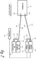
- Fig. 2 illustrates a non-limiting example of a scheme for connecting electrical loads, e.g. a battery charger 11A, a heater 11B, a DC/DC convertor 11C, and an air conditioner (AC) compressor motor 11D, to a battery pack 12, such as in an electric vehicle (not shown) by splicing a pair of positive cables 13A, 13C, 13B, 13D and a pair of negative cables 14A, 14C, 14B, 14D using the devices and methods presented herein.
- the inventors discovered that several circuits may be combined and share a single fuse 15, for example because the combined current of the electrical loads 11A-B and/or 11C-D is lower than the rated capacity of the fuse 15 or because the electrical loads are not used concurrently.
- the electrical loads 11A-B may also be connected to a controller 16 that enables the electrical loads 11A-B to operate one at a time so that they are not used concurrently or the controller 16 may monitor the current used by each of the electrical loads 11A-B and control each of the electrical loads 11A-B so that the total current used by the electrical loads 11A-B is less than the current rating required to blow, or open, the fuse 15B.
- connection system 20 illustrates a non-limiting example of the electrical connection system 20, hereinafter referred to as the connection system 20.
- the connection system 20 is configured to interconnect a battery pack 12 in an electric vehicle to two different electrical loads, such as a DC/DC convertor 11C and air conditioner (AC) compressor motor 11D.
- the connection system 20 includes a male connector 22 having two pairs of wire cables 24A-B, 26A-B and a female connector 28 having two pairs of shielded wire cables 13A, 13C, 14A, 14C.
- the male connector 22 has a male header 30 formed of an insulative material, such as glass filled polybutylene terephthalate (PBT), that is configured to be mounted to a conductive case (not shown) of one of the electrical loads, e.g. the DC/DC convertor 11C via fasteners, e.g. screws.
- the male header 30 includes a face seal 32 that is formed of a compliant elastomeric material and configured to seal the male header 30 to the conductive case thus inhibiting the intrusion of contaminants into the connection system 20 and the conductive case.
- the male connector 22 includes a conductive male shield 34 within the male header 30.
- This male shield 34 is electrically connected to the conductive case to provide an electrical connection between the shield conductors of the shielded wire cables 13A, 13C, 14A, 14C and the conductive case.
- the male shield 34 surrounds a male inner connector housing 36 formed of an insulating material, such as glass filled PBT, that is also disposed within the male header 30.
- This male inner connector housing 36 defines a number of cavities 38 that accept a pair of male power terminals 40A-B and female high voltage interlock (HVIL) terminals 42A-B.
- HVIL high voltage interlock
- the pair of male power terminals 40A-B terminate a first pair of wire cables 24A-B that supply electrical power from the connector system 20 to the DC/DC convertor 11C.
- This first pair of wire cables 24A-B does not need to be shielded because they are shielded by being contained within the conductive case of the DC/DC convertor 11C.
- the female HVIL terminals 42A-B are connected to a second pair of wire cables 26A-B that are interconnected with an HVIL control circuit (not shown).
- the HVIL control circuit inhibits operation of the DC/DC convertor 11C until the female HVIL terminals 42A-B are shorted together by a shunt terminal 44 in the female connector 28.
- the male connector 22 further includes a terminal position assurance (TPA) device 46 formed of an insulative material, such as glass filled PBT, that is configured to secure the male power terminals 40A-B and female HVIL terminals 42A-B within the male inner connector housing 36.
- TPA terminal position assurance
- the male connector 22 additionally includes a compliant connector seal 48 and seal retainer 50 configured to seal the male connector 22 to the female connector 28, thereby inhibiting contaminants from entering the connection system 20.
- the female connector 28 includes an outer connector housing 52 formed of an insulative material, e.g. glass filled PBT, that defines a locking arm 54 designed to secure the female connector 28 to the male connector 22 and a connector position assurance (CPA) device 56 that assures that the locking arm 54 cannot be activated to disconnect the male connector 22 from the female connector 28 unless the CPA device 56 is disengaged first.
- CPA connector position assurance
- the female connector 28 further includes a female inner connector housing 58 formed of an insulative material, such as glass filled PBT.
- the female inner connector housing 58 also defines a number of cavities 60 that are configured to accept two pairs of female power terminals 62A-B, 64A-B.
- a first pair of female power terminals 62A-B terminate the center conductors of a first pair of shielded wire cables 13A, 14A connected to the electrical vehicle battery pack 12 and a second pair of female power terminals 64A-B terminate the center conductors of a second pair of shielded wire cables 13C, 14C connected to a second electrical load, e.g. the AC compressor motor 11D.
- the center conductors of the first pair of shielded wire cables 13A, 14A have a larger cross section than the center conductors of the second pair of shielded wire cables 13C, 14C in order to allow the first shielded wire cables 13A, 14A to conduct a larger current from the battery pack 12 to both of the electrical loads 11C-D, wherein the second pair of shielded wire cables 13C, 14C carries a lower current from the DC/DC converter 11C to the AC compressor motor 11D.
- the outer shield conductors of the first and second pair of shielded wire cables 13A, 13C, 14A, 14C are terminated by conductive ferrules 63 that are interconnected to a conductive female shield 66 that surrounds the female inner connector housing 58.
- the female shield 66 is interconnected to the male shield 34, thereby providing electrical shielding of the male and female power terminals 40A-B, 60A-B, 62A-B and electrical continuity between the shield conductors and the conductive case.
- the female inner connector housing 58 also includes the conductive HVIL shunt terminal 44 that is configured to interconnect the female HVIL terminals 42A-B after the male and female power terminals 40A-B, 60A-B, 62A-B are properly connected.
- the HVIL shunt terminal 44 and female HVIL terminals 42A-B are configured so that they mate last and break first when the male and female connectors 22, 28 are being connected and disconnected respectively.
- the female connector 28 additionally includes a cable seal 68 formed of a compliant elastomeric material that surrounds each of the shielded wire cables 13A, 13C, 14A, 14C to inhibit contaminants from flowing into the connection system 20.
- the female connector 28 includes a strain relief device 70 as well.
- the strain relief device 70 is formed of an insulative material, such as a polyester compound. The strain relief device 70 retains the cable seal 68 within the outer connector housing 52 and affords terminal position assurance for the female power terminals 40A-B, 42A-B as well as providing strain relief for the shielded wire cables13A, 13C, 14A, 14C.
- the male power terminal 40 includes a connection portion 72 that defines two blade-like features 74, 76 that each project from the terminal 40 parallel to the longitudinal axis X of the terminal 40.
- the male power terminal 40 also includes an attachment portion 78 that defines a first pair of crimp wings 80 configured to attach the terminal 40 to the conductor of the wire cable 24 and a second pair of crimp wings 82 configured to attach the terminal 40 to the insulation jacket of the wire cable 24.
- the male power terminal 40 further includes a transition portion 84 intermediate the connection portion 72 and the attachment portion 78.
- the male power terminal 40 is formed of a sheet of conductive material, such as a C151 copper alloy by a stamping or blanking process.
- the first blade 74 of the male terminal 40 is wider than the second blade 76 to allow it to conduct a higher current from the battery pack 12 in order to supply power to both electrical loads at the same time, e.g. the DC/DC convertor 11C and the AC compressor motor 11D.
- the first blade 74 is 6.3 millimeters (mm) wide while the second blade 76 is 2.6 mm wide.
- the first blade 74 is also longer than the second blade 76 to allow it to interconnect with the first female power terminal 62 prior to connection of the second blade 76 with the second female power terminal 64.
- the first blade 74 projects 10.3 mm beyond the transition portion 84 while the second blade 76 projects 8.8 mm beyond the transition portion 84.
- first and second blades 74, 76 reduces the peak force required to mate the male and female connectors 22, 28.
- the maximum engage forces is less than 70 newtons.
- the tips of the first and second blades 74, 76 are beveled in two axes.
- the first and second blades 74, 76 are covered in a silver-based plating while the attachment portion 78 is covered by a nickel-based plating to improve inter-terminal conductivity and inhibit corrosion.
- two male power terminals 40A-B are disposed within the male inner connector housing 36 and arranged such that the first and second blades 74A, 76A of one male power terminal 40A are non-adjacent or at a diagonal to the corresponding blades of the other male power terminal 40B.
- the first female power terminals 62A-B are also wider than the second female power terminals 64A-B in order to properly accommodate the first and second male power terminals 40A-B.
- each male power terminal 40 defines a first shoulder 86 that projects laterally, i.e. substantially perpendicularly to the longitudinal axis X of the male power terminal 40, from a first mesial or outer edge 88 of the first blade 74.
- the transition portion 84 of each male power terminal 40 also defines a second shoulder 90 that projects laterally from a second mesial edge 92 of the second blade 76 that is opposite the first mesial edge 88 of the first blade 74.
- a width of the first shoulder 86 is greater than a width of the second shoulder 90. As best shown in Fig. 4 , these first and second shoulders 86, 90 interface with shallower and deeper slots 64, 96 in opposite sides of the male inner connector housing 36.
- a lateral edge of the first shoulder is configured to engage an end wall of the first slot and a lateral edge of the second shoulder is configured to engage another end wall of the second slot to ensure that the male power terminals 40A-B are properly arranged in the male inner connector housing 36 as described above.
- Fig. 5 shows that a distal or central region 98 of the transition portion 84 defines an aperture 100.
- This aperture 100 is characterized as having a generally rectangular shape.
- a lock feature 102 defined by a flexible beam 104 within the male inner connector housing 36 engages an edge 106 of the aperture 100 and secures the male power terminal 40 within the male inner connector housing 36.
- the lock features is located within the cavity to ensure that the lateral edge of the first shoulder is engaged with the end wall of the first slot and the lateral edge of the second shoulder is engaged with the end wall of the second slot.
- connection system 20 when the connection system 20 is fully connected, electrical current from the battery pack 12 flows through the first pair of shielded power cables to the electrical connector connection system 20 via the first female power terminals 40A-B. A portion of the current then flows to the DC/DC convertor 11C through the pair wire cables 24A-B joined to the attachment portions of the male power terminals 40A-B and the remaining portion of the current flows to the ac compressor motor 11D through the second pair of shielded cables 13C, 14C via the second blade 76.
- the electrical connector connection system 20 in the illustrated embodiment is used in an electric vehicle application, other embodiments of the system may be envisioned for other applications for splicing shielded wire cables.
- the male connector may not be mounted to a conductive case and the male shield may be configured to interconnect to a shielded cable using ferrules 63 similarly to the female shield 66.
- the illustrated electrical connector connection system 20 is configured to splice connect pairs of wire cables, other embodiments may be proposed to splice single wire cables.
- an electrical connector connection system 20 configured to provide electrical power to two different electrical loads and a method of splicing a plurality of shielded wire cable pairs 13A, 13C, 14A, 14C are provided.
- the electrical connector connection system 20 provides a shielded wire cable splice that is sealed from environmental contamination.
- the male and female connectors 22, 28 of the may be interconnected with a force of less than 75 newtons, eliminating the need to a mechanical assist to meet ergonomic requirements imposed by may automotive manufacturers.
- the electrical connection system 20 also reduces the length of shielded cables 13A, 13C, 14A, 14C required to interconnect multiple electrical loads 11C, 11D with the battery pack 12, providing the benefit of reduced material cost and simplified cable routing.
Landscapes
- Details Of Connecting Devices For Male And Female Coupling (AREA)
- Connector Housings Or Holding Contact Members (AREA)
Abstract
Description
- The invention relates to an electrical connector system, in particular to an electrical connector system configured to interconnect more than two high voltage electrical loads.
- Shielded wire cables typically include an insulated center conductor and a separate insulated shield conductor surrounding the center conductor insulation. The shield conductor may consist of a braided wire mesh, metal foil, or metalized film. The cables typically have a second insulation layer covering the shield conductor. Shielded wire cables have been long used for communications systems, such as in cable television transmission lines. Shielded wire cables are also finding use in high voltage applications in electric and hybrid electric vehicles. When shielded wire cables are spliced together, there is usually a need to electrically connect the shield conductors of the spliced cables as well as the center conductor, in order to maintain electrical continuity of the shield conductors. Interconnecting the shield conductors may be complicated because the shield conductors must be cut back from the spliced ends of the cable in order to join the center conductors. Interconnecting the shield conductors may be further complicated in a one-to-many splicing configuration, sometimes referred to as a Y-splice.
-
Fig. 1 illustrates a prior art scheme for connecting a number ofelectrical loads 1 to abattery pack 2, such as in an electric vehicle (not shown). Eachelectrical load 1 requires a pair of high voltage shielded wire cables (positive polarity 3 and negative polarity 4) running from thebattery pack 2 to theelectrical load 1 and aseparate fuse 5 protecting each of the circuits. - The subject matter discussed in the background section should not be assumed to be prior art merely as a result of its mention in the background section. Similarly, a problem mentioned in the background section or associated with the subject matter of the background section should not be assumed to have been previously recognized in the prior art. The subject matter in the background section merely represents different approaches, which in and of themselves may also be inventions.
- In accordance with a first embodiment of the invention, a male electrical terminal is provided. This terminal includes a connection portion that defines a first blade longitudinally projecting from the terminal and a second blade also longitudinally projecting from the terminal. A width of the first blade is less than a width of the second blade. A length of the first blade is less than a length of the second blade. The terminal also includes an attachment portion that defines a pair of crimp wings that are configured to attach the terminal to a wire cable. The terminal further includes a transition portion intermediate the connection portion and the attachment portion.
- The transition portion may define a first shoulder that laterally projects from a first mesial edge of the transition portion that is proximate the first blade. The transition portion may further define a second shoulder that laterally projects from a second mesial edge of the transition portion that is located opposite the first mesial edge. This second shoulder is proximate the second blade. A width of the first shoulder may be greater than a width of the second shoulder. A distal region of the transition portion may define an aperture that is characterized as having a generally rectangular shape.
- In accordance with a second embodiment of the invention, an electrical connector system is provided. The electrical connector system includes a male connector having a male terminal that defines a first blade that longitudinally projects from the male terminal and a second blade that also longitudinally projects from the male terminal. A width of the first blade is less than a width of the second blade. A length of the first blade is less than a length of the second blade. The male terminal further defines a pair of crimp wings that are configured to attach the male terminal to a wire cable. The electrical connector system also includes a female connector having a first female terminal that is configured to receive the first blade of the male terminal and a second female terminal configured to receive the second blade of the male terminal, thereby electrically interconnecting the first female terminal, the second female terminal, and the wire cable.
- The first blade may define a first shoulder that laterally projects from a mesial edge of the first blade and the second blade may define a second shoulder that laterally projects from another mesial edge of the second blade. A width of the first shoulder may be greater than a width of the second shoulder.
- The electrical connector system may further include a male connector body that defines a cavity configured to receive the male terminal. This cavity defines a first longitudinal slot that is configured to receive the first shoulder and defines a second longitudinal slot located opposite the first slot. The second slot has depth that is less than a depth of the first slot. The second slot is configured to receive the second shoulder. A lateral edge of the first shoulder is configured to engage an end wall of the first slot and a lateral edge of the second shoulder is configured to engage another end wall of the second slot.
- A distal region of the male terminal may define an aperture. The male connector body may define a snap feature that is configured to engage this aperture. The aperture may be characterized as having a rectangular shape.
- In accordance with a third embodiment of the invention, another electrical connector system is provided. The electrical connector system includes a male connector having a male terminal that defines a first blade that longitudinally project from the male terminal and a second blade that also longitudinally projects from the male terminal. A width of the first blade is less than a width of the second blade. The male terminal further defines a pair of crimp wings that are configured to attach the male terminal to a wire cable. The electrical connector system further includes a female connector having a first female terminal which is configured to receive the first blade and a second female terminal that is configured to receive the second blade. A first tip of the first blade has a first relative position and a second tip of the second blade has a second relative position that is different than the first relative position such that as the male connector is mated with the female connector, the first tip does not contact the first female terminal at the same time that the second tip contacts the second female terminal, thereby lowering a peak engagement force required to mate the male connector with the female connector. In addition, the first female terminal, the second female terminal, and the wire cable are electrically interconnected as the male connector is mated with the female connector. According to one particular embodiment, the peak engagement force required for mating the male connector with the female connector does not exceed 75 newtons.
- The first blade may define a first shoulder that laterally projects from a mesial edge of the first blade and the second blade may define a second shoulder that laterally projects from another mesial edge of the second blade. A width of the first shoulder may be greater than a width of the second shoulder.
- The electrical connector system may further include a male connector body that defines a cavity which is configured to receive the male terminal. This cavity defines a first longitudinal slot that is configured to receive the first shoulder and defines a second longitudinal slot located opposite the first slot. The second slot has depth that is less than a depth of the first slot. The second slot is configured to receive the second shoulder. A lateral edge of the first shoulder is configured to engage an end wall of the first slot and a lateral edge of the second shoulder is configured to engage another end wall of the second slot.
- A distal region of the male terminal may define an aperture. The male connector body may define a snap feature that is configured to engage this aperture. The aperture may be characterized as having a rectangular shape.
- The present invention will now be described, by way of example with reference to the accompanying drawings, in which:
-
Fig. 1 is a schematic diagram of a prior art electrical load connection scheme; -
Fig. 2 is a schematic diagram of an electrical load connection scheme in accordance with one embodiment; -
Fig. 3 is a perspective view of an electrical connector system according to one embodiment; -
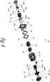
Fig. 4 is an exploded perspective view of the electrical connector system ofFig. 3 according to one embodiment; -
Fig. 5 is a side view of a male power terminal of the electrical connector system ofFig. 3 according to one embodiment; and -
Fig. 6 is a cut away perspective view of the male power terminal ofFig, 5 secured within an inner housing of the electrical connector system ofFig. 3 according to one embodiment. - A male electrical terminal and an electrical connection system employing this male electrical terminal are presented herein.
-
Fig. 2 illustrates a non-limiting example of a scheme for connecting electrical loads, e.g. abattery charger 11A, aheater 11B, a DC/DC convertor 11C, and an air conditioner (AC)compressor motor 11D, to abattery pack 12, such as in an electric vehicle (not shown) by splicing a pair ofpositive cables negative cables electrical loads 11A-B and/or 11C-D is lower than the rated capacity of the fuse 15 or because the electrical loads are not used concurrently. Theelectrical loads 11A-B may also be connected to acontroller 16 that enables theelectrical loads 11A-B to operate one at a time so that they are not used concurrently or thecontroller 16 may monitor the current used by each of theelectrical loads 11A-B and control each of theelectrical loads 11A-B so that the total current used by theelectrical loads 11A-B is less than the current rating required to blow, or open, thefuse 15B. - The inventors realized that a pair of high voltage shielded
wire cables Fig. 2 with anelectrical connection system 20 that connects the core conductors of the shieldedwire cables wire cables electrical loads 11A-D to thebattery pack 12, thus reducing shielded wire cable cost, weight, packaging space, and wire routing complexity for the wiring harness. Because multipleelectrical loads 11A-B, 11C-D can share asingle fuse battery pack 12 could also be reduced; further reducing cost and complexity of the battery pack by reducing the number of fuses and cable connectors compared with the prior art scheme ofFig. 1 described in the BACKGROUND OF THE INVENTION. -
Figs. 2 through 4 illustrate a non-limiting example of theelectrical connection system 20, hereinafter referred to as theconnection system 20. Theconnection system 20 is configured to interconnect abattery pack 12 in an electric vehicle to two different electrical loads, such as a DC/DC convertor 11C and air conditioner (AC)compressor motor 11D. Theconnection system 20 includes amale connector 22 having two pairs ofwire cables 24A-B, 26A-B and afemale connector 28 having two pairs of shieldedwire cables male connector 22 has amale header 30 formed of an insulative material, such as glass filled polybutylene terephthalate (PBT), that is configured to be mounted to a conductive case (not shown) of one of the electrical loads, e.g. the DC/DC convertor 11C via fasteners, e.g. screws. Themale header 30 includes aface seal 32 that is formed of a compliant elastomeric material and configured to seal themale header 30 to the conductive case thus inhibiting the intrusion of contaminants into theconnection system 20 and the conductive case. - The
male connector 22 includes a conductivemale shield 34 within themale header 30. Thismale shield 34 is electrically connected to the conductive case to provide an electrical connection between the shield conductors of the shieldedwire cables male shield 34 surrounds a maleinner connector housing 36 formed of an insulating material, such as glass filled PBT, that is also disposed within themale header 30. This maleinner connector housing 36 defines a number ofcavities 38 that accept a pair ofmale power terminals 40A-B and female high voltage interlock (HVIL)terminals 42A-B. - The pair of
male power terminals 40A-B terminate a first pair ofwire cables 24A-B that supply electrical power from theconnector system 20 to the DC/DC convertor 11C. This first pair ofwire cables 24A-B does not need to be shielded because they are shielded by being contained within the conductive case of the DC/DC convertor 11C. Thefemale HVIL terminals 42A-B are connected to a second pair ofwire cables 26A-B that are interconnected with an HVIL control circuit (not shown). The HVIL control circuit inhibits operation of the DC/DC convertor 11C until thefemale HVIL terminals 42A-B are shorted together by ashunt terminal 44 in thefemale connector 28. - The
male connector 22 further includes a terminal position assurance (TPA)device 46 formed of an insulative material, such as glass filled PBT, that is configured to secure themale power terminals 40A-B andfemale HVIL terminals 42A-B within the maleinner connector housing 36. Themale connector 22 additionally includes acompliant connector seal 48 and sealretainer 50 configured to seal themale connector 22 to thefemale connector 28, thereby inhibiting contaminants from entering theconnection system 20. - The
female connector 28 includes anouter connector housing 52 formed of an insulative material, e.g. glass filled PBT, that defines a lockingarm 54 designed to secure thefemale connector 28 to themale connector 22 and a connector position assurance (CPA)device 56 that assures that the lockingarm 54 cannot be activated to disconnect themale connector 22 from thefemale connector 28 unless theCPA device 56 is disengaged first. - The
female connector 28 further includes a femaleinner connector housing 58 formed of an insulative material, such as glass filled PBT. The femaleinner connector housing 58 also defines a number ofcavities 60 that are configured to accept two pairs offemale power terminals 62A-B, 64A-B. A first pair offemale power terminals 62A-B terminate the center conductors of a first pair of shieldedwire cables vehicle battery pack 12 and a second pair offemale power terminals 64A-B terminate the center conductors of a second pair of shieldedwire cables AC compressor motor 11D. The center conductors of the first pair of shieldedwire cables wire cables wire cables battery pack 12 to both of theelectrical loads 11C-D, wherein the second pair of shieldedwire cables DC converter 11C to theAC compressor motor 11D. The outer shield conductors of the first and second pair of shieldedwire cables conductive ferrules 63 that are interconnected to a conductivefemale shield 66 that surrounds the femaleinner connector housing 58. When themale connector 22 is mated with thefemale connector 28, thefemale shield 66 is interconnected to themale shield 34, thereby providing electrical shielding of the male andfemale power terminals 40A-B, 60A-B, 62A-B and electrical continuity between the shield conductors and the conductive case. - The female
inner connector housing 58 also includes the conductiveHVIL shunt terminal 44 that is configured to interconnect thefemale HVIL terminals 42A-B after the male andfemale power terminals 40A-B, 60A-B, 62A-B are properly connected. TheHVIL shunt terminal 44 andfemale HVIL terminals 42A-B are configured so that they mate last and break first when the male andfemale connectors - The
female connector 28 additionally includes acable seal 68 formed of a compliant elastomeric material that surrounds each of the shieldedwire cables connection system 20. Thefemale connector 28 includes astrain relief device 70 as well. Thestrain relief device 70 is formed of an insulative material, such as a polyester compound. Thestrain relief device 70 retains thecable seal 68 within theouter connector housing 52 and affords terminal position assurance for thefemale power terminals 40A-B, 42A-B as well as providing strain relief for the shielded wire cables13A, 13C, 14A, 14C. - As shown in
Fig. 5 , themale power terminal 40 includes aconnection portion 72 that defines two blade-like features male power terminal 40 also includes anattachment portion 78 that defines a first pair ofcrimp wings 80 configured to attach the terminal 40 to the conductor of the wire cable 24 and a second pair ofcrimp wings 82 configured to attach the terminal 40 to the insulation jacket of the wire cable 24. Themale power terminal 40 further includes atransition portion 84 intermediate theconnection portion 72 and theattachment portion 78. Themale power terminal 40 is formed of a sheet of conductive material, such as a C151 copper alloy by a stamping or blanking process. - The
first blade 74 of themale terminal 40 is wider than thesecond blade 76 to allow it to conduct a higher current from thebattery pack 12 in order to supply power to both electrical loads at the same time, e.g. the DC/DC convertor 11C and theAC compressor motor 11D. In the illustrated example, thefirst blade 74 is 6.3 millimeters (mm) wide while thesecond blade 76 is 2.6 mm wide. Thefirst blade 74 is also longer than thesecond blade 76 to allow it to interconnect with the first female power terminal 62 prior to connection of thesecond blade 76 with the second female power terminal 64. In the illustrated example, thefirst blade 74 projects 10.3 mm beyond thetransition portion 84 while thesecond blade 76 projects 8.8 mm beyond thetransition portion 84. This staggered arrangement of the first andsecond blades female connectors connection system 20, the maximum engage forces is less than 70 newtons. The tips of the first andsecond blades - The first and
second blades attachment portion 78 is covered by a nickel-based plating to improve inter-terminal conductivity and inhibit corrosion. As best shown inFig. 4 , twomale power terminals 40A-B are disposed within the maleinner connector housing 36 and arranged such that the first and second blades 74A, 76A of onemale power terminal 40A are non-adjacent or at a diagonal to the corresponding blades of the othermale power terminal 40B. The firstfemale power terminals 62A-B are also wider than the secondfemale power terminals 64A-B in order to properly accommodate the first and secondmale power terminals 40A-B. - The
transition portion 84 of eachmale power terminal 40 defines afirst shoulder 86 that projects laterally, i.e. substantially perpendicularly to the longitudinal axis X of themale power terminal 40, from a first mesial orouter edge 88 of thefirst blade 74. Thetransition portion 84 of eachmale power terminal 40 also defines asecond shoulder 90 that projects laterally from a secondmesial edge 92 of thesecond blade 76 that is opposite the firstmesial edge 88 of thefirst blade 74. A width of thefirst shoulder 86 is greater than a width of thesecond shoulder 90. As best shown inFig. 4 , these first andsecond shoulders deeper slots 64, 96 in opposite sides of the maleinner connector housing 36. A lateral edge of the first shoulder is configured to engage an end wall of the first slot and a lateral edge of the second shoulder is configured to engage another end wall of the second slot to ensure that themale power terminals 40A-B are properly arranged in the maleinner connector housing 36 as described above. -
Fig. 5 shows that a distal orcentral region 98 of thetransition portion 84 defines anaperture 100. Thisaperture 100 is characterized as having a generally rectangular shape. As shown inFig. 6 , alock feature 102 defined by aflexible beam 104 within the maleinner connector housing 36 engages anedge 106 of theaperture 100 and secures themale power terminal 40 within the maleinner connector housing 36. The lock features is located within the cavity to ensure that the lateral edge of the first shoulder is engaged with the end wall of the first slot and the lateral edge of the second shoulder is engaged with the end wall of the second slot. - Without subscribing to any particular theory of operation, when the
connection system 20 is fully connected, electrical current from thebattery pack 12 flows through the first pair of shielded power cables to the electricalconnector connection system 20 via the firstfemale power terminals 40A-B. A portion of the current then flows to the DC/DC convertor 11C through thepair wire cables 24A-B joined to the attachment portions of themale power terminals 40A-B and the remaining portion of the current flows to theac compressor motor 11D through the second pair of shieldedcables second blade 76. - While the electrical
connector connection system 20 in the illustrated embodiment is used in an electric vehicle application, other embodiments of the system may be envisioned for other applications for splicing shielded wire cables. For example, the male connector may not be mounted to a conductive case and the male shield may be configured to interconnect to a shieldedcable using ferrules 63 similarly to thefemale shield 66. In addition, while the illustrated electricalconnector connection system 20 is configured to splice connect pairs of wire cables, other embodiments may be proposed to splice single wire cables. - Accordingly, an electrical
connector connection system 20 configured to provide electrical power to two different electrical loads and a method of splicing a plurality of shielded wire cable pairs 13A, 13C, 14A, 14C are provided. The electricalconnector connection system 20 provides a shielded wire cable splice that is sealed from environmental contamination. The male andfemale connectors electrical connection system 20 also reduces the length of shieldedcables electrical loads battery pack 12, providing the benefit of reduced material cost and simplified cable routing. - While this invention has been described in terms of the preferred embodiments thereof, it is not intended to be so limited, but rather only to the extent set forth in the claims that follow. Moreover, the use of the terms first, second, etc. does not denote any order of importance, but rather the terms first, second, etc. are used to distinguish one element from another. Furthermore, the use of the terms a, an, etc. do not denote a limitation of quantity, but rather denote the presence of at least one of the referenced items.
Claims (13)
- A male electrical terminal (40), comprising:a connection portion (72) that defines a first blade (74) longitudinally projecting from said terminal (40) and a second blade (76) longitudinally projecting from said terminal (40), wherein a first blade (74) width is less than a second blade (76) width and wherein a first blade (74) length is less than a second blade (76) length;an attachment portion (78) that defines a pair of crimp wings (80) configured to attach said terminal (40) to a wire cable (24); anda transition portion (84) intermediate the connection portion (72) and the attachment portion (78), wherein the transition portion (84) defines a first shoulder (86) laterally projecting from a first mesial edge (88) proximate the first blade (74) and wherein the transition portion (84) defines a second shoulder (90) laterally projecting from a second mesial edge (92) opposite the first mesial edge (88) and proximate the second blade (76).
- The male electrical terminal (40) according to claim 1, wherein a first shoulder (86) width is greater than a second shoulder (90) width.
- The male electrical terminal (40) according to claim 1 or 2, wherein a distal region of the transition portion (84) defines an aperture (100).
- An electrical connector system (20), comprising:a male connector (22) having a male terminal (40), preferably according to one of the claims 1-3, that defines a first blade (74) longitudinally projecting from the male terminal (40) and a second blade (76) longitudinally projecting from said male terminal (40), wherein a first blade (74) width is less than a second blade (76) width and wherein a first blade (74) length is less than a second blade (76) length, said male terminal (40) further defines a pair of crimp wings (80) configured to attach the male terminal (40) to a wire cable (24); anda female connector (28) having a first female terminal (40) configured to receive the first blade (74) and a second female terminal (40) configured to receive the second blade (76), thereby electrically interconnecting the first female terminal (40), the second female terminal (40), and the wire cable (24).
- The electrical connector system (20) according to claim 4, wherein the first blade (74) defines a first shoulder (86) laterally projecting from a mesial edge (88) of the first blade (74) and wherein the second blade (76) defines a second shoulder (90) laterally projecting from another mesial edge (92) of the second blade (76).
- The electrical connector system (20) according to claim 5, wherein a first shoulder (86) width is greater than the second shoulder (90) width.
- The electrical connector system (20) according to claim 5 or 6, further comprising a male connector (22) body defining a cavity configured to receive the male terminal (40), wherein the cavity defines a first longitudinal slot configured to receive the first shoulder (86) and defines a second longitudinal slot opposite the first slot, said second slot having a second slot depth less than a first slot depth and configured to receive the second shoulder (90) and wherein a lateral first shoulder (86) edge is configured to engage an end wall of the first slot and a lateral second shoulder (90) edge is configured to engage an end wall of the second slot.
- The electrical connector system (20) according to claim 7, wherein a distal region of the male terminal (40) defines an aperture (100) and wherein the male connector (22) body defines a snap feature configured to engage the aperture (100).
- The electrical connector system (20) according to claim 8, wherein the aperture (100) is characterized as having a rectangular shape.
- An electrical connector system (20), according to one of the claims 4-9, wherein a first tip of the first blade (74) has a first relative position and a second tip of the second blade (76) has a second relative position that is different than the first relative position such that as the male connector (22) is mated with the female connector (28), thereby electrically interconnecting the first female terminal (40), the second female terminal (40), and the wire cable (24), the first tip does not contact the first female terminal (40) at the same time that the second tip contacts the second female terminal (40), thereby lowering a peak engagement force required to mate the male connector (22) with the female connector (28).
- The electrical connector system (20) according to claim 10, wherein the peak engagement force required for mating the male connector (22) with the female connector (28) does not exceed 75 Newton.
- The electrical connector system (20) according to claim 10 or 11, wherein the first blade (74) defines a first shoulder (86) laterally projecting from a mesial edge (88) of the first blade (74) and wherein the second blade (76) defines a second shoulder (90) laterally projecting from a mesial edge (92) of the second blade (76).
- The electrical connector system (20) according to claim 12, wherein a first shoulder (86) width is greater than a second shoulder (90) width.
Applications Claiming Priority (1)
| Application Number | Priority Date | Filing Date | Title |
|---|---|---|---|
| US15/095,515 US9653859B1 (en) | 2016-04-11 | 2016-04-11 | Electrical connector system |
Publications (2)
| Publication Number | Publication Date |
|---|---|
| EP3246997A1 true EP3246997A1 (en) | 2017-11-22 |
| EP3246997B1 EP3246997B1 (en) | 2019-11-06 |
Family
ID=58461217
Family Applications (1)
| Application Number | Title | Priority Date | Filing Date |
|---|---|---|---|
| EP17163936.2A Active EP3246997B1 (en) | 2016-04-11 | 2017-03-30 | Electrical connector system |
Country Status (4)
| Country | Link |
|---|---|
| US (1) | US9653859B1 (en) |
| EP (1) | EP3246997B1 (en) |
| KR (1) | KR101778918B1 (en) |
| CN (1) | CN107302147B (en) |
Families Citing this family (13)
| Publication number | Priority date | Publication date | Assignee | Title |
|---|---|---|---|---|
| US9948048B2 (en) * | 2015-05-15 | 2018-04-17 | Yazaki North America, Inc. | Splitter terminal and connector |
| US9905953B1 (en) | 2016-09-30 | 2018-02-27 | Slobodan Pavlovic | High power spring-actuated electrical connector |
| US9954347B1 (en) * | 2017-06-19 | 2018-04-24 | Delphi Technologies, Inc. | Wire harness assembly and seal retainer therefore |
| KR102492963B1 (en) | 2017-11-17 | 2023-01-31 | 한국단자공업 주식회사 | High voltage connector assembly |
| DE112018006954T5 (en) | 2018-02-26 | 2020-11-26 | Inventive Consulting Llc | Spring actuated electrical connector for high performance applications |
| US10312624B1 (en) * | 2018-04-20 | 2019-06-04 | Delphi Technologies, Llc | Connector with primary lock reinforcement |
| CN112956084B (en) | 2018-06-07 | 2023-10-03 | 皇家精密制品有限责任公司 | Electrical connector assembly with internal spring member |
| DE102019104655A1 (en) * | 2019-02-25 | 2020-08-27 | Phoenix Contact E-Mobility Gmbh | High current wiring for charging connectors and vehicle |
| DE112020003846T5 (en) | 2019-09-09 | 2022-05-12 | Royal Precision Products Llc | CONNECTOR RECORDING SYSTEM WITH READABLE AND RECORDABLE MARKERS |
| US11721942B2 (en) | 2019-09-09 | 2023-08-08 | Eaton Intelligent Power Limited | Connector system for a component in a power management system in a motor vehicle |
| JP2023536817A (en) * | 2020-07-29 | 2023-08-30 | イートン インテリジェント パワー リミテッド | Electrical connector system with cylindrical terminal body |
| US11223155B1 (en) * | 2020-10-20 | 2022-01-11 | Deere & Company | Electrical connector cavity plug and cover assembly |
| JP1714181S (en) * | 2021-10-28 | 2022-05-06 | Housing for electrical connectors |
Citations (5)
| Publication number | Priority date | Publication date | Assignee | Title |
|---|---|---|---|---|
| US5052951A (en) * | 1990-01-24 | 1991-10-01 | Draw-Tite, Inc. | Terminal block |
| US5915984A (en) * | 1996-08-26 | 1999-06-29 | Dekko Engineering, Inc. | Modular electrical outlet and connector assembly |
| WO2013001249A1 (en) * | 2011-06-30 | 2013-01-03 | Tbi | Hybrid socket for single-filament or dual-filament bulb |
| WO2013133348A2 (en) * | 2012-03-05 | 2013-09-12 | Yazaki Corporation | Connection structure of electronic components |
| WO2014070851A1 (en) * | 2012-10-31 | 2014-05-08 | Delphi Technologies, Inc. | Device and method for splicing shielded wire cables |
Family Cites Families (38)
| Publication number | Priority date | Publication date | Assignee | Title |
|---|---|---|---|---|
| US3263202A (en) * | 1963-05-22 | 1966-07-26 | Emtec Inc | One-piece dual-barrel electrical connector |
| JPS6358776A (en) * | 1986-08-27 | 1988-03-14 | アンプ インコ−ポレ−テツド | 4-sheet leaf receptacle contact |
| US4884050A (en) | 1988-07-18 | 1989-11-28 | Kozel Emmett L | Blade terminal tap fuse |
| US5295847A (en) * | 1990-01-16 | 1994-03-22 | Yazaki Corporation | Branch junction box and busbars for branch connection |
| DE19613749A1 (en) * | 1996-04-01 | 1997-10-02 | Taller Gmbh | Contact element group of electrical multiple plug connection for electric device esp. domestic appliance |
| US6257938B1 (en) * | 1998-12-16 | 2001-07-10 | Stoneridge, Inc. | Databus multiplexing connection system |
| JP3286783B2 (en) * | 1999-02-18 | 2002-05-27 | 日本航空電子工業株式会社 | contact |
| DE19944280C1 (en) * | 1999-09-15 | 2001-02-01 | Framatome Connectors Int | Electric plug pin socket contact has insertion guides provided on same side as spring contact arms each divided into 2 parts by elongate slit |
| US6302709B1 (en) * | 2000-06-05 | 2001-10-16 | Power-One, Inc. | Multiple function high current interconnect with integrated bus bar |
| JP3729720B2 (en) * | 2000-09-28 | 2005-12-21 | アルプス電気株式会社 | Card connector device |
| TW476466U (en) * | 2000-09-29 | 2002-02-11 | Hon Hai Prec Ind Co Ltd | Electrical connector |
| US6802748B2 (en) * | 2000-12-22 | 2004-10-12 | Tyco Electronics Corporation | Spring contact for connectors |
| JP4181307B2 (en) * | 2001-01-19 | 2008-11-12 | 山一電機株式会社 | Card connector |
| US7114989B2 (en) * | 2003-04-18 | 2006-10-03 | Molex Incorporated | Coaxial electrical connector |
| JP4046033B2 (en) * | 2003-07-30 | 2008-02-13 | 住友電装株式会社 | Half-fitting detection structure for bus bars in electrical junction boxes for automobiles |
| JP4020885B2 (en) * | 2004-04-27 | 2007-12-12 | ヒロセ電機株式会社 | Card connector and card contact terminal used therefor |
| CN2786824Y (en) * | 2005-04-13 | 2006-06-07 | 上海莫仕连接器有限公司 | Power supply connector |
| DE102005061641A1 (en) * | 2005-12-22 | 2007-06-28 | Amphenol-Tuchel-Electronics Gmbh | Smart card connector, has connectors that are in contact with control tip such that tip is pressed for short time at contact surface of card before achieving reading position of card, and metal cover attached at upper side of carrier |
| US7134893B1 (en) * | 2006-03-23 | 2006-11-14 | Yazaki North America, Inc. | Pull-lock terminal connection system |
| US7300313B1 (en) * | 2006-06-02 | 2007-11-27 | Tyco Electronics Corporation | Electrical connector having staggered contacts |
| US7267583B1 (en) | 2006-09-19 | 2007-09-11 | Delphi Technologies, Inc. | Electrical connection system |
| US7361065B1 (en) * | 2006-11-03 | 2008-04-22 | Tyco Electronics Corporation | Connector assembly for conductive plates |
| US7905731B2 (en) * | 2007-05-21 | 2011-03-15 | Fci Americas Technology, Inc. | Electrical connector with stress-distribution features |
| US7762857B2 (en) * | 2007-10-01 | 2010-07-27 | Fci Americas Technology, Inc. | Power connectors with contact-retention features |
| JP4425987B1 (en) * | 2009-06-10 | 2010-03-03 | イリソ電子工業株式会社 | connector |
| JP5307656B2 (en) * | 2009-07-15 | 2013-10-02 | 富士通コンポーネント株式会社 | connector |
| US8616926B2 (en) * | 2009-08-17 | 2013-12-31 | Norman R. Byrne | Solid wire terminal |
| CA2713314C (en) * | 2009-08-17 | 2016-02-09 | Norman R. Byrne | Solid wire terminal |
| JP5233962B2 (en) * | 2009-11-10 | 2013-07-10 | 住友電装株式会社 | Joint connector and wire harness |
| JP5613029B2 (en) * | 2010-11-25 | 2014-10-22 | 矢崎総業株式会社 | Busba |
| JP5668655B2 (en) * | 2011-09-20 | 2015-02-12 | 株式会社オートネットワーク技術研究所 | Conductive plate and joint connector |
| JP5760971B2 (en) * | 2011-09-20 | 2015-08-12 | 株式会社オートネットワーク技術研究所 | Earth connection device |
| US9362665B2 (en) * | 2011-09-29 | 2016-06-07 | Autonetworks Technologies, Ltd. | Joint connector with pairs of locking lances and communication space extending between the pairs of locking lances |
| US9033750B2 (en) * | 2012-08-15 | 2015-05-19 | Tyco Electronics Corporation | Electrical contact |
| JP2014054005A (en) * | 2012-09-05 | 2014-03-20 | Yazaki Corp | Electric connection box |
| JP6009285B2 (en) * | 2012-09-05 | 2016-10-19 | 矢崎総業株式会社 | Busba |
| JP5938067B2 (en) * | 2013-05-24 | 2016-06-22 | イリソ電子工業株式会社 | connector |
| JP5798214B2 (en) * | 2013-06-17 | 2015-10-21 | モレックス インコーポレイテドMolex Incorporated | Contact terminal for card socket |
-
2016
- 2016-04-11 US US15/095,515 patent/US9653859B1/en active Active
-
2017
- 2017-03-30 EP EP17163936.2A patent/EP3246997B1/en active Active
- 2017-04-03 KR KR1020170042919A patent/KR101778918B1/en active IP Right Grant
- 2017-04-10 CN CN201710229380.XA patent/CN107302147B/en active Active
Patent Citations (5)
| Publication number | Priority date | Publication date | Assignee | Title |
|---|---|---|---|---|
| US5052951A (en) * | 1990-01-24 | 1991-10-01 | Draw-Tite, Inc. | Terminal block |
| US5915984A (en) * | 1996-08-26 | 1999-06-29 | Dekko Engineering, Inc. | Modular electrical outlet and connector assembly |
| WO2013001249A1 (en) * | 2011-06-30 | 2013-01-03 | Tbi | Hybrid socket for single-filament or dual-filament bulb |
| WO2013133348A2 (en) * | 2012-03-05 | 2013-09-12 | Yazaki Corporation | Connection structure of electronic components |
| WO2014070851A1 (en) * | 2012-10-31 | 2014-05-08 | Delphi Technologies, Inc. | Device and method for splicing shielded wire cables |
Also Published As
| Publication number | Publication date |
|---|---|
| CN107302147A (en) | 2017-10-27 |
| US9653859B1 (en) | 2017-05-16 |
| CN107302147B (en) | 2019-04-23 |
| EP3246997B1 (en) | 2019-11-06 |
| KR101778918B1 (en) | 2017-09-14 |
Similar Documents
| Publication | Publication Date | Title |
|---|---|---|
| EP3246997B1 (en) | Electrical connector system | |
| EP2686919B1 (en) | High voltage connector assembly | |
| JP6685422B2 (en) | Terminal assembly with multi-wire flat cable | |
| CN108475889B (en) | High-power electric connector | |
| US9601742B2 (en) | Busbar module unit | |
| US9337466B2 (en) | Power terminal connector | |
| CN109478628B (en) | Connector assembly for battery system | |
| US10418765B2 (en) | Multi-wire planar cable for a monitoring system of a battery module | |
| CN104521075B (en) | Interconnecting assembly and interconnecting method for vehicle fitting | |
| EP3050162B1 (en) | Electrical system | |
| CN110198861B (en) | Electrical connection device, electrical architecture, and electric or hybrid electric vehicle | |
| EP4099519A1 (en) | Male and female power terminal assembly, female and male power terminals | |
| CN115332848A (en) | Contact device for double bus, joint and contact system | |
| WO2013178434A1 (en) | Interconnection assembly for vehicle devices and method of interconnection |
Legal Events
| Date | Code | Title | Description |
|---|---|---|---|
| PUAI | Public reference made under article 153(3) epc to a published international application that has entered the european phase |
Free format text: ORIGINAL CODE: 0009012 |
|
| STAA | Information on the status of an ep patent application or granted ep patent |
Free format text: STATUS: THE APPLICATION HAS BEEN PUBLISHED |
|
| AK | Designated contracting states |
Kind code of ref document: A1 Designated state(s): AL AT BE BG CH CY CZ DE DK EE ES FI FR GB GR HR HU IE IS IT LI LT LU LV MC MK MT NL NO PL PT RO RS SE SI SK SM TR |
|
| AX | Request for extension of the european patent |
Extension state: BA ME |
|
| STAA | Information on the status of an ep patent application or granted ep patent |
Free format text: STATUS: REQUEST FOR EXAMINATION WAS MADE |
|
| 17P | Request for examination filed |
Effective date: 20180522 |
|
| RBV | Designated contracting states (corrected) |
Designated state(s): AL AT BE BG CH CY CZ DE DK EE ES FI FR GB GR HR HU IE IS IT LI LT LU LV MC MK MT NL NO PL PT RO RS SE SI SK SM TR |
|
| STAA | Information on the status of an ep patent application or granted ep patent |
Free format text: STATUS: EXAMINATION IS IN PROGRESS |
|
| 17Q | First examination report despatched |
Effective date: 20180827 |
|
| RAP1 | Party data changed (applicant data changed or rights of an application transferred) |
Owner name: APTIV TECHNOLOGIES LIMITED |
|
| GRAP | Despatch of communication of intention to grant a patent |
Free format text: ORIGINAL CODE: EPIDOSNIGR1 |
|
| STAA | Information on the status of an ep patent application or granted ep patent |
Free format text: STATUS: GRANT OF PATENT IS INTENDED |
|
| RIC1 | Information provided on ipc code assigned before grant |
Ipc: H01R 31/02 20060101ALN20190503BHEP Ipc: H01R 4/18 20060101ALN20190503BHEP Ipc: H01R 13/41 20060101ALI20190503BHEP Ipc: H01R 11/07 20060101AFI20190503BHEP Ipc: H01R 13/04 20060101ALI20190503BHEP |
|
| RIC1 | Information provided on ipc code assigned before grant |
Ipc: H01R 13/41 20060101ALI20190514BHEP Ipc: H01R 31/02 20060101ALN20190514BHEP Ipc: H01R 13/04 20060101ALI20190514BHEP Ipc: H01R 11/07 20060101AFI20190514BHEP Ipc: H01R 4/18 20060101ALN20190514BHEP |
|
| INTG | Intention to grant announced |
Effective date: 20190528 |
|
| GRAS | Grant fee paid |
Free format text: ORIGINAL CODE: EPIDOSNIGR3 |
|
| GRAA | (expected) grant |
Free format text: ORIGINAL CODE: 0009210 |
|
| STAA | Information on the status of an ep patent application or granted ep patent |
Free format text: STATUS: THE PATENT HAS BEEN GRANTED |
|
| AK | Designated contracting states |
Kind code of ref document: B1 Designated state(s): AL AT BE BG CH CY CZ DE DK EE ES FI FR GB GR HR HU IE IS IT LI LT LU LV MC MK MT NL NO PL PT RO RS SE SI SK SM TR |
|
| REG | Reference to a national code |
Ref country code: GB Ref legal event code: FG4D |
|
| REG | Reference to a national code |
Ref country code: CH Ref legal event code: EP Ref country code: AT Ref legal event code: REF Ref document number: 1200068 Country of ref document: AT Kind code of ref document: T Effective date: 20191115 |
|
| REG | Reference to a national code |
Ref country code: IE Ref legal event code: FG4D |
|
| REG | Reference to a national code |
Ref country code: DE Ref legal event code: R096 Ref document number: 602017008328 Country of ref document: DE |
|
| REG | Reference to a national code |
Ref country code: NL Ref legal event code: MP Effective date: 20191106 |
|
| REG | Reference to a national code |
Ref country code: LT Ref legal event code: MG4D |
|
| PG25 | Lapsed in a contracting state [announced via postgrant information from national office to epo] |
Ref country code: NL Free format text: LAPSE BECAUSE OF FAILURE TO SUBMIT A TRANSLATION OF THE DESCRIPTION OR TO PAY THE FEE WITHIN THE PRESCRIBED TIME-LIMIT Effective date: 20191106 Ref country code: GR Free format text: LAPSE BECAUSE OF FAILURE TO SUBMIT A TRANSLATION OF THE DESCRIPTION OR TO PAY THE FEE WITHIN THE PRESCRIBED TIME-LIMIT Effective date: 20200207 Ref country code: LT Free format text: LAPSE BECAUSE OF FAILURE TO SUBMIT A TRANSLATION OF THE DESCRIPTION OR TO PAY THE FEE WITHIN THE PRESCRIBED TIME-LIMIT Effective date: 20191106 Ref country code: BG Free format text: LAPSE BECAUSE OF FAILURE TO SUBMIT A TRANSLATION OF THE DESCRIPTION OR TO PAY THE FEE WITHIN THE PRESCRIBED TIME-LIMIT Effective date: 20200206 Ref country code: FI Free format text: LAPSE BECAUSE OF FAILURE TO SUBMIT A TRANSLATION OF THE DESCRIPTION OR TO PAY THE FEE WITHIN THE PRESCRIBED TIME-LIMIT Effective date: 20191106 Ref country code: LV Free format text: LAPSE BECAUSE OF FAILURE TO SUBMIT A TRANSLATION OF THE DESCRIPTION OR TO PAY THE FEE WITHIN THE PRESCRIBED TIME-LIMIT Effective date: 20191106 Ref country code: SE Free format text: LAPSE BECAUSE OF FAILURE TO SUBMIT A TRANSLATION OF THE DESCRIPTION OR TO PAY THE FEE WITHIN THE PRESCRIBED TIME-LIMIT Effective date: 20191106 Ref country code: PL Free format text: LAPSE BECAUSE OF FAILURE TO SUBMIT A TRANSLATION OF THE DESCRIPTION OR TO PAY THE FEE WITHIN THE PRESCRIBED TIME-LIMIT Effective date: 20191106 Ref country code: PT Free format text: LAPSE BECAUSE OF FAILURE TO SUBMIT A TRANSLATION OF THE DESCRIPTION OR TO PAY THE FEE WITHIN THE PRESCRIBED TIME-LIMIT Effective date: 20200306 Ref country code: NO Free format text: LAPSE BECAUSE OF FAILURE TO SUBMIT A TRANSLATION OF THE DESCRIPTION OR TO PAY THE FEE WITHIN THE PRESCRIBED TIME-LIMIT Effective date: 20200206 |
|
| PG25 | Lapsed in a contracting state [announced via postgrant information from national office to epo] |
Ref country code: RS Free format text: LAPSE BECAUSE OF FAILURE TO SUBMIT A TRANSLATION OF THE DESCRIPTION OR TO PAY THE FEE WITHIN THE PRESCRIBED TIME-LIMIT Effective date: 20191106 Ref country code: HR Free format text: LAPSE BECAUSE OF FAILURE TO SUBMIT A TRANSLATION OF THE DESCRIPTION OR TO PAY THE FEE WITHIN THE PRESCRIBED TIME-LIMIT Effective date: 20191106 Ref country code: IS Free format text: LAPSE BECAUSE OF FAILURE TO SUBMIT A TRANSLATION OF THE DESCRIPTION OR TO PAY THE FEE WITHIN THE PRESCRIBED TIME-LIMIT Effective date: 20200306 |
|
| PG25 | Lapsed in a contracting state [announced via postgrant information from national office to epo] |
Ref country code: AL Free format text: LAPSE BECAUSE OF FAILURE TO SUBMIT A TRANSLATION OF THE DESCRIPTION OR TO PAY THE FEE WITHIN THE PRESCRIBED TIME-LIMIT Effective date: 20191106 |
|
| PG25 | Lapsed in a contracting state [announced via postgrant information from national office to epo] |
Ref country code: RO Free format text: LAPSE BECAUSE OF FAILURE TO SUBMIT A TRANSLATION OF THE DESCRIPTION OR TO PAY THE FEE WITHIN THE PRESCRIBED TIME-LIMIT Effective date: 20191106 Ref country code: CZ Free format text: LAPSE BECAUSE OF FAILURE TO SUBMIT A TRANSLATION OF THE DESCRIPTION OR TO PAY THE FEE WITHIN THE PRESCRIBED TIME-LIMIT Effective date: 20191106 Ref country code: ES Free format text: LAPSE BECAUSE OF FAILURE TO SUBMIT A TRANSLATION OF THE DESCRIPTION OR TO PAY THE FEE WITHIN THE PRESCRIBED TIME-LIMIT Effective date: 20191106 Ref country code: EE Free format text: LAPSE BECAUSE OF FAILURE TO SUBMIT A TRANSLATION OF THE DESCRIPTION OR TO PAY THE FEE WITHIN THE PRESCRIBED TIME-LIMIT Effective date: 20191106 Ref country code: DK Free format text: LAPSE BECAUSE OF FAILURE TO SUBMIT A TRANSLATION OF THE DESCRIPTION OR TO PAY THE FEE WITHIN THE PRESCRIBED TIME-LIMIT Effective date: 20191106 |
|
| REG | Reference to a national code |
Ref country code: DE Ref legal event code: R097 Ref document number: 602017008328 Country of ref document: DE |
|
| REG | Reference to a national code |
Ref country code: AT Ref legal event code: MK05 Ref document number: 1200068 Country of ref document: AT Kind code of ref document: T Effective date: 20191106 |
|
| PG25 | Lapsed in a contracting state [announced via postgrant information from national office to epo] |
Ref country code: SK Free format text: LAPSE BECAUSE OF FAILURE TO SUBMIT A TRANSLATION OF THE DESCRIPTION OR TO PAY THE FEE WITHIN THE PRESCRIBED TIME-LIMIT Effective date: 20191106 Ref country code: SM Free format text: LAPSE BECAUSE OF FAILURE TO SUBMIT A TRANSLATION OF THE DESCRIPTION OR TO PAY THE FEE WITHIN THE PRESCRIBED TIME-LIMIT Effective date: 20191106 |
|
| PLBE | No opposition filed within time limit |
Free format text: ORIGINAL CODE: 0009261 |
|
| STAA | Information on the status of an ep patent application or granted ep patent |
Free format text: STATUS: NO OPPOSITION FILED WITHIN TIME LIMIT |
|
| 26N | No opposition filed |
Effective date: 20200807 |
|
| PG25 | Lapsed in a contracting state [announced via postgrant information from national office to epo] |
Ref country code: MC Free format text: LAPSE BECAUSE OF FAILURE TO SUBMIT A TRANSLATION OF THE DESCRIPTION OR TO PAY THE FEE WITHIN THE PRESCRIBED TIME-LIMIT Effective date: 20191106 |
|
| REG | Reference to a national code |
Ref country code: CH Ref legal event code: PL |
|
| PG25 | Lapsed in a contracting state [announced via postgrant information from national office to epo] |
Ref country code: SI Free format text: LAPSE BECAUSE OF FAILURE TO SUBMIT A TRANSLATION OF THE DESCRIPTION OR TO PAY THE FEE WITHIN THE PRESCRIBED TIME-LIMIT Effective date: 20191106 Ref country code: AT Free format text: LAPSE BECAUSE OF FAILURE TO SUBMIT A TRANSLATION OF THE DESCRIPTION OR TO PAY THE FEE WITHIN THE PRESCRIBED TIME-LIMIT Effective date: 20191106 |
|
| REG | Reference to a national code |
Ref country code: BE Ref legal event code: MM Effective date: 20200331 |
|
| PG25 | Lapsed in a contracting state [announced via postgrant information from national office to epo] |
Ref country code: LU Free format text: LAPSE BECAUSE OF NON-PAYMENT OF DUE FEES Effective date: 20200330 |
|
| PG25 | Lapsed in a contracting state [announced via postgrant information from national office to epo] |
Ref country code: IE Free format text: LAPSE BECAUSE OF NON-PAYMENT OF DUE FEES Effective date: 20200330 Ref country code: IT Free format text: LAPSE BECAUSE OF FAILURE TO SUBMIT A TRANSLATION OF THE DESCRIPTION OR TO PAY THE FEE WITHIN THE PRESCRIBED TIME-LIMIT Effective date: 20191106 Ref country code: CH Free format text: LAPSE BECAUSE OF NON-PAYMENT OF DUE FEES Effective date: 20200331 Ref country code: LI Free format text: LAPSE BECAUSE OF NON-PAYMENT OF DUE FEES Effective date: 20200331 |
|
| PG25 | Lapsed in a contracting state [announced via postgrant information from national office to epo] |
Ref country code: BE Free format text: LAPSE BECAUSE OF NON-PAYMENT OF DUE FEES Effective date: 20200331 |
|
| PG25 | Lapsed in a contracting state [announced via postgrant information from national office to epo] |
Ref country code: TR Free format text: LAPSE BECAUSE OF FAILURE TO SUBMIT A TRANSLATION OF THE DESCRIPTION OR TO PAY THE FEE WITHIN THE PRESCRIBED TIME-LIMIT Effective date: 20191106 Ref country code: MT Free format text: LAPSE BECAUSE OF FAILURE TO SUBMIT A TRANSLATION OF THE DESCRIPTION OR TO PAY THE FEE WITHIN THE PRESCRIBED TIME-LIMIT Effective date: 20191106 Ref country code: CY Free format text: LAPSE BECAUSE OF FAILURE TO SUBMIT A TRANSLATION OF THE DESCRIPTION OR TO PAY THE FEE WITHIN THE PRESCRIBED TIME-LIMIT Effective date: 20191106 |
|
| PG25 | Lapsed in a contracting state [announced via postgrant information from national office to epo] |
Ref country code: MK Free format text: LAPSE BECAUSE OF FAILURE TO SUBMIT A TRANSLATION OF THE DESCRIPTION OR TO PAY THE FEE WITHIN THE PRESCRIBED TIME-LIMIT Effective date: 20191106 |
|
| PGFP | Annual fee paid to national office [announced via postgrant information from national office to epo] |
Ref country code: FR Payment date: 20230325 Year of fee payment: 7 |
|
| P01 | Opt-out of the competence of the unified patent court (upc) registered |
Effective date: 20230420 |
|
| PGFP | Annual fee paid to national office [announced via postgrant information from national office to epo] |
Ref country code: DE Payment date: 20240322 Year of fee payment: 8 Ref country code: GB Payment date: 20240319 Year of fee payment: 8 |