EP3246931A1 - Interlock mechanism for an earthing switch of a gas insulated substation - Google Patents
Interlock mechanism for an earthing switch of a gas insulated substation Download PDFInfo
- Publication number
- EP3246931A1 EP3246931A1 EP16170388.9A EP16170388A EP3246931A1 EP 3246931 A1 EP3246931 A1 EP 3246931A1 EP 16170388 A EP16170388 A EP 16170388A EP 3246931 A1 EP3246931 A1 EP 3246931A1
- Authority
- EP
- European Patent Office
- Prior art keywords
- axle
- swivel lever
- interlock system
- blocking position
- free
- Prior art date
- Legal status (The legal status is an assumption and is not a legal conclusion. Google has not performed a legal analysis and makes no representation as to the accuracy of the status listed.)
- Granted
Links
Images


Classifications
-
- H—ELECTRICITY
- H01—ELECTRIC ELEMENTS
- H01H—ELECTRIC SWITCHES; RELAYS; SELECTORS; EMERGENCY PROTECTIVE DEVICES
- H01H31/00—Air-break switches for high tension without arc-extinguishing or arc-preventing means
- H01H31/003—Earthing switches
-
- H—ELECTRICITY
- H01—ELECTRIC ELEMENTS
- H01H—ELECTRIC SWITCHES; RELAYS; SELECTORS; EMERGENCY PROTECTIVE DEVICES
- H01H33/00—High-tension or heavy-current switches with arc-extinguishing or arc-preventing means
- H01H33/02—Details
- H01H33/46—Interlocking mechanisms
-
- H—ELECTRICITY
- H01—ELECTRIC ELEMENTS
- H01H—ELECTRIC SWITCHES; RELAYS; SELECTORS; EMERGENCY PROTECTIVE DEVICES
- H01H31/00—Air-break switches for high tension without arc-extinguishing or arc-preventing means
- H01H31/02—Details
- H01H31/04—Interlocking mechanisms
-
- H—ELECTRICITY
- H01—ELECTRIC ELEMENTS
- H01H—ELECTRIC SWITCHES; RELAYS; SELECTORS; EMERGENCY PROTECTIVE DEVICES
- H01H9/00—Details of switching devices, not covered by groups H01H1/00 - H01H7/00
- H01H9/20—Interlocking, locking, or latching mechanisms
- H01H9/28—Interlocking, locking, or latching mechanisms for locking switch parts by a key or equivalent removable member
- H01H9/285—Locking mechanisms incorporated in the switch assembly and operable by a key or a special tool
Definitions
- the invention relates to securing from unintended or unauthorized operation an electric earthing switch of a gas insulated substation, such as an earthing switch allowing to electrically connect electric lines to the earth.
- an electric line to be connected to the earth comprises typically one or three bus bars mounted in a leak-proof casing filled with dielectric gas such as SF6.
- the earthing switch of such a substation comprises a housing secured to the casing surrounding the bus bars, and connections to these bus bars and to an earth connector of the substation. It encloses an actuating mechanism including cogwheel reductor, and a drive motor, allowing to operate the switch from its open status where it disconnects the bus bas from the earth to its closed status where it connects the bus bars to the earth, by means of its drive motor.
- the goal of the invention is to provide an interlock mechanism to ensure that such an earthing switch be secured against unauthorized or unintended operation.
- the invention relates to an interlock system to block or free a cogwheel of an actuation mechanism of an earth switch for gas insulated substation, this interlock system comprising a housing enclosing :
- the interlock mechanism can easily be mounted to an existing earthing switch without requiring expansive adaptation of this earthing switch.
- the invention also relates to an interlock system such as designed above, wherein the inner extremity of the rotating axle carries a cam disc cooperating with the swivel lever to move it from its blocking position to its free position and conversely upon rotation of this axle, and comprising a spring having an extremity secured to the swivel lever and another extremity secured to the housing to continuously press the swivel lever against the cam disk.
- the invention also relates to an interlock system such as defined above, wherein the spring continuously pulls a part of the swivel lever to its blocking position.
- the invention also relates to an interlock system such as defined above, where the end of the swivel lever comprises a pinion to be meshed with two meshed cogwheels of the actuation mechanism when the swivel lever is in the blocking position, and at a distance from these two meshed cogwheels when the swivel lever is in the free position.
- the invention also relates to an interlock system such as defined above, comprising a pivoting lever movable along the rotating axle by the actuation mechanism between an open and a closed position corresponding to electrically open and closed statuses of the earthing switch, a feather key carried by the rotating axle and located between the open end closed positions of the pivoting lever when the rotating axle is in the blocking position, to ensure that the rotating axle cannot be moved from its free position to its blocking position if the pivoting lever is at an intermediate position between its open and closed positions.
- the invention also relates to an earthing switch equipped with an interlock system such as defined above.
- an interlock system 1 is fixed to the housing 2 of an earthing switch 3 of an insulated gas station, this earthing switch further comprising in the enclosure of its housing an actuation mechanism which is not visible in figure 1 .
- the interlock system 1 comprises a cast housing 4 enclosing an interlock mechanism 6 which cooperates with the actuation mechanism 7 of the earthing switch 3, two keylocks 8 and 9 and a rotating knob 11 both carried at the outer face of the housing 4.
- the housing 4 has the general shape of a parallelepiped having one of its faces open, i.e. comprising a main or bottom flat wall 12 continued by four walls 13, 14, 16, 17 surrounding this bottom wall 12 and extending each almost perpendicular to this bottom wall 12.
- the four surrounding walls 13, 14, 16, 17 are terminated by a common peripheral edge forming a flange 18 comprising holes 19 by means of which this housing 4 is bolted on the housing of the earthing switch.
- the interlock system can easily be fitted to an existing earthing switch by replacing the cover plate of this earthing switch, without any further modification.
- the interlock system which can be seen in more details in figure 3 and 4 comprises an axle 21 extending along an axis AX parallel to the main wall 12 and perpendicular to the front surrounding wall 13.
- This axle 21 has a first extremity supported by a central support 22 protruding from the center of the main wall 12 and comprising a bearing.
- the second extremity of this axle 21 protrudes through the front wall 13 which forms the other bearing supporting this axle 21.
- the knob 11 is secured to the second extremity of the axle 21 which protrudes out of the front wall 13, allowing an operator to rotate the axle 21 by turning its knob 11.
- the actuation mechanism of the earthing switch comprises two cogwheels 23, 24 and a free pinion 26 meshed in cogwheel 23, which are located closed to the central support 22 and rotate around corresponding axes which are parallel to axis AX.
- This actuation mechanism comprises other components which are not shown on the figures.
- the cogwheel 23 can be blocked in rotation by the free end of a swivel lever 27 which is carried by the central support 22, and which can rotate relatively to an axis of rotation parallel to axis AX and at a distance from this axis.
- This lever 27 carries a pinion 28 at its free end.
- this swivel lever 27 When this swivel lever 27 is in a free position where it is retracted as in figures 2 , 5 , 6, 7 and 8 , its free end is at a distance from cogwheel 23 and pinion 26, allowing the actuation mechanism of the earthing switch to be operated. When this swivel lever 27 is in its blocking position where it is deployed, as in figures 3, 4 and 9 , the pinion 28 of its free end is meshed with cogwheel 23 and with pinion 26 to block their rotation, rendering operation of the actuation mechanism impossible.
- the swivel lever 27 is moved from its blocking position to its free position and conversely by the rotation of axis 21. More particularly, this axis 21 carries a cam disk 29 at its first extremity, which is applied against a corresponding part of swivel lever 27. Additionally, a return spring 31 has a first extremity fixed to the central support 22 and a second extremity fixed to the extremity of lever 27 which is opposite to its free extremity which carries pinion 28. Thanks to this spring 31, the swivel lever 27 is continuously pulled to its blocking position, and it is continuously pressed against cam disk 29.
- cam disk 29 When the axle 21 is in its free position as in figure 5 , i.e. one eighth of turn counterclockwise from its blocking position, cam disk 29 is pressed against a portion of swivel lever 27 opposite to its free end and distant from its rotation axis, counteracting the action of spring 31, to retract swivel lever 27 at its free position.
- the central support 22 comprises two stopping pins 32, 33 protruding from its face oriented towards the front wall 13 and which limit rotation of the cam disk 29, and as a result from axle 21, between its free position and its blocking position.
- the knob has two pairs of holes each lying diametrically opposed and each shifted by an angle. Turning the keys drives the bolts of the keylocks into the holes of the knob and locks so any further rotation of the rational axle.
- an operator wanting to operate the earthing switch from its electrically open status as in figure 3 to its electrically closed status has to firstly use the keys 34 and 36 to open keylocks 8 and 9 to allow operation of knob 11. Once the keylocks 8 and 9 are unlocked, the operator has to rotate knob 11 counterclockwise of one eighth turn to retract the swivel lever 27 to its free position, which corresponds to the situation of figure 6 .
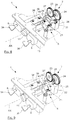
- the earthing switch can be operated from its open status to its closed status, for example manually or by commanding its integrated motor drive, which leads to the situation seen in figure 8 .
- the operator can turn the knob of one eighth turn clockwise to deploy swivel lever 27 to its blocking position in order to block further operation of the earthing switch, and lock the keylocks 8 and 9 with keys 34 and 36, which corresponds to situation of figure 9 .
- the interlock system according to the invention further comprises means to ensure that it cannot be locked when the earthing switch is at an intermediate status between its open and closed status, such as in figure 7 .
- the interlock mechanism comprises a pivoting lever 37 which is rotatable around an axis AY perpendicular to the bottom wall 12 of the housing, and which is movable along the rotating axis 21.
- This pivoting lever 37 is coupled to a corresponding tappet of the actuation mechanism of the earthing switch, which moves between an open and a closed position corresponding to the open status and to the closed status of the earthing switch.
- the tappet of the actuation mechanism comprises a stud or finger protruding from its extremity and which is inserted into a corresponding oblong hole 40 of the pivoting lever 37. This hole extending along the length of the pivoting lever 37 in the vicinity of the rotating axis 21.
- the pivoting lever 37 when the earthing switch is in its electrically open status as in figure 2 , 3 and 6 , the pivoting lever 37 is in its open position, with its free end closed to the front wall 13. When the earthing switch is in its electrically closed status as in figure 8 and 9 , the pivoting lever 37 is at its closed position with its free end distant from the front wall 13 and closer to the central support 22.
- the free end of the pivoting lever 37 extends beneath a retaining plate 38 which extends parallel to the bottom wall 12 and which is above the level of the rotating axis 21 relatively to the bottom wall 12 to which it is fixedly secured.
- the rotating axis 21 comprises a feather key 39 protruding out of its outer cylindrical surface in a region located between the open position and the closed position of the pivoting lever 37.
- the feather key 39 When the rotating axis 21 is in its free position, the feather key 39 extends laterally, i.e. away from the path of the pivoting lever 37, allowing the pivoting lever 37 to move freely between its extreme positions. But when the rotating axis 21 is at its blocking position, the feather key 39 extends opposite to the bottom wall 12, i.e. into the path of pivoting lever 37.
- the pivoting lever 37 comprises two stop pins protruding from its bottom face and which stop firmly the feather key 39 in case of rotation of axis 21 to the blocking position when this pivoting lever 37 is at an intermediate position as in figure 7 .
- the feather key and the stop pins have each a height which is superior to the distance between the axle 21 and the pivoting lever 37.
Landscapes
- Driving Mechanisms And Operating Circuits Of Arc-Extinguishing High-Tension Switches (AREA)
- Switch Cases, Indication, And Locking (AREA)
- Mechanisms For Operating Contacts (AREA)
Abstract
- a swivel lever having an end moveable between a blocking position pressed against the cogwheel, and a free position at a distance from the cogwheel ;
- a rotating axle movable between a blocking position and a free position, this axle having an inner extremity carrying a cam disc to move the swivel lever, and an outer extremity protruding out of the housing (4) to actuate this axle ;
- a spring having an extremity secured to the swivel lever and another extremity secured to the housing (4) to press the swivel lever against the cam disk ;
- a key lock (8, 9) secured to the housing (4) and cooperating with the axle (21) to lock it in its blocking or free position.
Description
- The invention relates to securing from unintended or unauthorized operation an electric earthing switch of a gas insulated substation, such as an earthing switch allowing to electrically connect electric lines to the earth.
- In a gas insulated substation, an electric line to be connected to the earth comprises typically one or three bus bars mounted in a leak-proof casing filled with dielectric gas such as SF6.
- The earthing switch of such a substation comprises a housing secured to the casing surrounding the bus bars, and connections to these bus bars and to an earth connector of the substation. It encloses an actuating mechanism including cogwheel reductor, and a drive motor, allowing to operate the switch from its open status where it disconnects the bus bas from the earth to its closed status where it connects the bus bars to the earth, by means of its drive motor.
- Most of the time there is also a possibility to operate the switch manually by means of an additional hand crank in order to allow operation in cases where the drive motor cannot be used.
- The goal of the invention is to provide an interlock mechanism to ensure that such an earthing switch be secured against unauthorized or unintended operation.
- The invention relates to an interlock system to block or free a cogwheel of an actuation mechanism of an earth switch for gas insulated substation, this interlock system comprising a housing enclosing :
- a swivel lever having an end moveable between a blocking position pressed against the cogwheel, and a free position at a distance from the cogwheel ;
- a rotating axle movable between a blocking position and a free position, having an inner extremity cooperating with the swivel lever to move it from its blocking position to its free position and conversely upon rotation of this axle, and an outer extremity protruding at an outer face of the housing to allow actuation of this axle by an operator;
- a key lock secured to the housing and cooperating with the axle to lock this axle in its blocking position or in its free position.
- With this arrangement, the interlock mechanism can easily be mounted to an existing earthing switch without requiring expansive adaptation of this earthing switch.
- The invention also relates to an interlock system such as designed above, wherein the inner extremity of the rotating axle carries a cam disc cooperating with the swivel lever to move it from its blocking position to its free position and conversely upon rotation of this axle, and comprising a spring having an extremity secured to the swivel lever and another extremity secured to the housing to continuously press the swivel lever against the cam disk.
- The invention also relates to an interlock system such as defined above, wherein the spring continuously pulls a part of the swivel lever to its blocking position.
- The invention also relates to an interlock system such as defined above, where the end of the swivel lever comprises a pinion to be meshed with two meshed cogwheels of the actuation mechanism when the swivel lever is in the blocking position, and at a distance from these two meshed cogwheels when the swivel lever is in the free position.
- The invention also relates to an interlock system such as defined above, comprising a pivoting lever movable along the rotating axle by the actuation mechanism between an open and a closed position corresponding to electrically open and closed statuses of the earthing switch, a feather key carried by the rotating axle and located between the open end closed positions of the pivoting lever when the rotating axle is in the blocking position, to ensure that the rotating axle cannot be moved from its free position to its blocking position if the pivoting lever is at an intermediate position between its open and closed positions.
- The invention also relates to an earthing switch equipped with an interlock system such as defined above.
-
-
Figure 1 is a perspective view of an earthing switch equipped with an interlock module according to the invention ; -
Figure 2 is a perspective view showing the inner face of the housing of the interlock system according to the invention with its components in the free position when the earthing switch is in its open status ; -
Figure 3 is a perspective view of the components of the interlock system according to the invention in the blocked position when the earthing switch is in the open status ; -
Figure 4 is a front view of the components of the interlock system according to the invention in the blocked position ; -
Figure 5 is a front view of the components of the interlock system according to the invention in the free position ; -
Figure 6 is a perspective view of the components of the interlock system according to the invention in the free position when the earthing switch is in its open status ; -
Figure 7 is a perspective view of the components of the interlock system according to the invention in the free position when the earthing switch is being operated from its open status to its closed status; -
Figure 8 is a perspective view of the components of the interlock system according to the invention in the free position when the earthing switch is in its closed status ; -
Figure 9 is a perspective view of the components of the interlock system according to the invention in the blocked position when the earthing switch is in its closed status. - In
figure 1 , aninterlock system 1 according to the invention is fixed to thehousing 2 of anearthing switch 3 of an insulated gas station, this earthing switch further comprising in the enclosure of its housing an actuation mechanism which is not visible infigure 1 . - As seen in
figure 2 , theinterlock system 1 comprises a cast housing 4 enclosing aninterlock mechanism 6 which cooperates with theactuation mechanism 7 of theearthing switch 3, twokeylocks knob 11 both carried at the outer face of the housing 4. - The housing 4 has the general shape of a parallelepiped having one of its faces open, i.e. comprising a main or bottom
flat wall 12 continued by fourwalls bottom wall 12 and extending each almost perpendicular to thisbottom wall 12. The four surroundingwalls flange 18 comprisingholes 19 by means of which this housing 4 is bolted on the housing of the earthing switch. - With this housing, the interlock system can easily be fitted to an existing earthing switch by replacing the cover plate of this earthing switch, without any further modification.
- The interlock system which can be seen in more details in
figure 3 and 4 comprises anaxle 21 extending along an axis AX parallel to themain wall 12 and perpendicular to thefront surrounding wall 13. Thisaxle 21 has a first extremity supported by acentral support 22 protruding from the center of themain wall 12 and comprising a bearing. The second extremity of thisaxle 21 protrudes through thefront wall 13 which forms the other bearing supporting thisaxle 21. - The
knob 11 is secured to the second extremity of theaxle 21 which protrudes out of thefront wall 13, allowing an operator to rotate theaxle 21 by turning itsknob 11. - The actuation mechanism of the earthing switch comprises two
cogwheels free pinion 26 meshed incogwheel 23, which are located closed to thecentral support 22 and rotate around corresponding axes which are parallel to axis AX. This actuation mechanism comprises other components which are not shown on the figures. - The
cogwheel 23 can be blocked in rotation by the free end of aswivel lever 27 which is carried by thecentral support 22, and which can rotate relatively to an axis of rotation parallel to axis AX and at a distance from this axis. Thislever 27 carries apinion 28 at its free end. - When this
swivel lever 27 is in a free position where it is retracted as infigures 2 ,5 ,6, 7 and8 , its free end is at a distance fromcogwheel 23 andpinion 26, allowing the actuation mechanism of the earthing switch to be operated. When thisswivel lever 27 is in its blocking position where it is deployed, as infigures 3, 4 and9 , thepinion 28 of its free end is meshed withcogwheel 23 and withpinion 26 to block their rotation, rendering operation of the actuation mechanism impossible. - The
swivel lever 27 is moved from its blocking position to its free position and conversely by the rotation ofaxis 21. More particularly, thisaxis 21 carries acam disk 29 at its first extremity, which is applied against a corresponding part ofswivel lever 27. Additionally, areturn spring 31 has a first extremity fixed to thecentral support 22 and a second extremity fixed to the extremity oflever 27 which is opposite to its free extremity which carriespinion 28. Thanks to thisspring 31, theswivel lever 27 is continuously pulled to its blocking position, and it is continuously pressed againstcam disk 29. - When the
axle 21 is in its blocking position as infigure 4 , the cam disk is pressed to a central portion ofswivel lever 27, this central portion being closed to its axis of rotation, allowing the action ofspring 31 to expandswivel lever 27 at its blocking position. - When the
axle 21 is in its free position as infigure 5 , i.e. one eighth of turn counterclockwise from its blocking position,cam disk 29 is pressed against a portion ofswivel lever 27 opposite to its free end and distant from its rotation axis, counteracting the action ofspring 31, to retractswivel lever 27 at its free position. - As it can be seen on
figures 4 and 5 , thecentral support 22 comprises twostopping pins front wall 13 and which limit rotation of thecam disk 29, and as a result fromaxle 21, between its free position and its blocking position. - Practically, the two
keylocks front wall 13 at either sides ofknob 11, allow to lockaxle 21 in its blocking position and in its free position. The knob has two pairs of holes each lying diametrically opposed and each shifted by an angle. Turning the keys drives the bolts of the keylocks into the holes of the knob and locks so any further rotation of the rational axle. - Accordingly, an operator wanting to operate the earthing switch from its electrically open status as in
figure 3 to its electrically closed status has to firstly use thekeys keylocks knob 11. Once thekeylocks knob 11 counterclockwise of one eighth turn to retract theswivel lever 27 to its free position, which corresponds to the situation offigure 6 . At this stage, the earthing switch can be operated from its open status to its closed status, for example manually or by commanding its integrated motor drive, which leads to the situation seen infigure 8 . - At that stage, the operator can turn the knob of one eighth turn clockwise to deploy
swivel lever 27 to its blocking position in order to block further operation of the earthing switch, and lock thekeylocks keys figure 9 . - The interlock system according to the invention further comprises means to ensure that it cannot be locked when the earthing switch is at an intermediate status between its open and closed status, such as in
figure 7 . - The interlock mechanism comprises a
pivoting lever 37 which is rotatable around an axis AY perpendicular to thebottom wall 12 of the housing, and which is movable along therotating axis 21. Thispivoting lever 37 is coupled to a corresponding tappet of the actuation mechanism of the earthing switch, which moves between an open and a closed position corresponding to the open status and to the closed status of the earthing switch. - More particularly, the tappet of the actuation mechanism comprises a stud or finger protruding from its extremity and which is inserted into a corresponding
oblong hole 40 of thepivoting lever 37. This hole extending along the length of thepivoting lever 37 in the vicinity of therotating axis 21. - When the mechanism is switched from its open to its closed status, the tapet rotates in a plane perpendicular to the
bottom wall 12 and comprising the AX axis, with the stud staying inserted inhole 40. This results in the stud moving according to a circular path of large radius which extends mainly along theaxis 21, to move the pivotinglever 37 from its open to its closed position. Converse movement is obtained when switching the mechanism from closed to open status. - Accordingly, when the earthing switch is in its electrically open status as in
figure 2 ,3 and6 , the pivotinglever 37 is in its open position, with its free end closed to thefront wall 13. When the earthing switch is in its electrically closed status as infigure 8 and 9 , the pivotinglever 37 is at its closed position with its free end distant from thefront wall 13 and closer to thecentral support 22. - The free end of the pivoting
lever 37 extends beneath a retainingplate 38 which extends parallel to thebottom wall 12 and which is above the level of the rotatingaxis 21 relatively to thebottom wall 12 to which it is fixedly secured. - The rotating
axis 21 comprises afeather key 39 protruding out of its outer cylindrical surface in a region located between the open position and the closed position of the pivotinglever 37. - When the rotating
axis 21 is in its free position, thefeather key 39 extends laterally, i.e. away from the path of the pivotinglever 37, allowing the pivotinglever 37 to move freely between its extreme positions. But when the rotatingaxis 21 is at its blocking position, thefeather key 39 extends opposite to thebottom wall 12, i.e. into the path of pivotinglever 37. - The result is that if the pivoting
lever 37 is at an intermediate position as infigure 7 , between an open and a closed status of the earthing switch, the rotatingaxis 21 cannot be operated from its free position to its blocking position. Practically, in such a movement the feather key 39 encounters the pivotinglever 37, forbidding the rotatingaxis 21 to reach the blocking position. - To improve efficiency of the arrangement, the pivoting
lever 37 comprises two stop pins protruding from its bottom face and which stop firmly thefeather key 39 in case of rotation ofaxis 21 to the blocking position when this pivotinglever 37 is at an intermediate position as infigure 7 . The feather key and the stop pins have each a height which is superior to the distance between theaxle 21 and the pivotinglever 37. - Thanks to this feather key 39 which can interfere with the pivoting
lever 37 at an intermediate position, it is not possible to lock the interlock system when the earthing switch is at an intermediate status between open and closed.
Claims (6)
- Interlock system (1) to block or free a cogwheel (23) of an actuation mechanism (7) of an earth switch (3) for gas insulated substation, this interlock system (1) comprising a housing (4) enclosing :- a swivel lever (27) having an end moveable between a blocking position pressed against the cogwheel, and a free position at a distance from the cogwheel ;- a rotating axle (21) movable between a blocking position and a free position, having an inner extremity cooperating with the swivel lever (27) to move it from its blocking position to its free position and conversely upon rotation of this axle (21), and an outer extremity protruding at an outer face of the housing (4) to allow actuation of this axle (21) by an operator;- a key lock (8, 9) secured to the housing (4) and cooperating with the axle (21) to lock this axle in its blocking position or in its free position.
- Interlock system according to claim 1, wherein the inner extremity of the rotating axle (21) carries a cam disc (29) cooperating with the swivel lever (27) to move it from its blocking position to its free position and conversely upon rotation of this axle (21), and comprising a spring (31) having an extremity secured to the swivel lever (27) and another extremity secured to the housing (4) to continuously press the swivel lever (27) against the cam disk (29).
- Interlock system according to claim 2, wherein the spring (31) continuously pulls a part of the swivel lever (27) to its blocking position.
- Interlock system according to claim 3, where the end of the swivel lever (27) comprises a pinion (26) to be meshed with two meshed cogwheels (23, 26) of the actuation mechanism (7) when the swivel lever (27) is in the blocking position, and at a distance from these two meshed cogwheels (23, 26) when the swivel lever (27) is in the free position.
- Interlock system according to any of claims 1 or 4, comprising a pivoting lever (37) movable along the rotating axle (21) by the actuation mechanism (7) between an open and a closed position corresponding to electrically open and closed statuses of the earthing switch (3), a feather key (39) carried by the rotating axle (21) and located between the open end closed positions of the pivoting lever (37) when the rotating axle (21) is in the blocking position, to ensure that the rotating axle (21) cannot be moved from its free position to its blocking position if the pivoting lever (37) is at an intermediate position between its open and closed positions.
- Earthing switch equipped with an interlock system according to any of the previous claims.
Priority Applications (2)
| Application Number | Priority Date | Filing Date | Title |
|---|---|---|---|
| EP16170388.9A EP3246931B1 (en) | 2016-05-19 | 2016-05-19 | Interlock mechanism for an earthing switch of a gas insulated substation |
| CN201710356766.7A CN107403704A (en) | 2016-05-19 | 2017-05-19 | Mutual interlocking gear for the earthed switch of gas insulated transformer substation |
Applications Claiming Priority (1)
| Application Number | Priority Date | Filing Date | Title |
|---|---|---|---|
| EP16170388.9A EP3246931B1 (en) | 2016-05-19 | 2016-05-19 | Interlock mechanism for an earthing switch of a gas insulated substation |
Publications (2)
| Publication Number | Publication Date |
|---|---|
| EP3246931A1 true EP3246931A1 (en) | 2017-11-22 |
| EP3246931B1 EP3246931B1 (en) | 2019-04-10 |
Family
ID=56026705
Family Applications (1)
| Application Number | Title | Priority Date | Filing Date |
|---|---|---|---|
| EP16170388.9A Active EP3246931B1 (en) | 2016-05-19 | 2016-05-19 | Interlock mechanism for an earthing switch of a gas insulated substation |
Country Status (2)
| Country | Link |
|---|---|
| EP (1) | EP3246931B1 (en) |
| CN (1) | CN107403704A (en) |
Families Citing this family (1)
| Publication number | Priority date | Publication date | Assignee | Title |
|---|---|---|---|---|
| CN111341596B (en) * | 2020-03-26 | 2025-02-07 | 广东电网有限责任公司 | A device for preventing accidental closing of grounding switch under power |
Citations (4)
| Publication number | Priority date | Publication date | Assignee | Title |
|---|---|---|---|---|
| US20060105880A1 (en) * | 2004-11-18 | 2006-05-18 | Areva T & D Ag | Mechanical control device for an electrical switchgear with three switching positions, provided with a selection lever cooperating with a cam |
| US20110303518A1 (en) * | 2010-06-10 | 2011-12-15 | Lsis Co., Ltd. | Interlock apparatus for solid insulated switchgear |
| US20130206554A1 (en) * | 2012-02-09 | 2013-08-15 | Kennedy Amoako Darko | Interlock system for switchgear |
| WO2014010110A1 (en) * | 2012-07-13 | 2014-01-16 | 三菱電機株式会社 | Switch gear |
Family Cites Families (3)
| Publication number | Priority date | Publication date | Assignee | Title |
|---|---|---|---|---|
| CN201038043Y (en) * | 2007-03-11 | 2008-03-19 | 郑文秀 | Switching mechanism for intelligent double-power automatic switching device |
| CN202167429U (en) * | 2011-08-12 | 2012-03-14 | 苏州未来电器有限公司 | Clutch system for energy storage electrically-operated apparatus |
| CN203871254U (en) * | 2014-05-29 | 2014-10-08 | 厦门兴厦控电气有限公司 | Operating mechanism of three-station isolation switch |
-
2016
- 2016-05-19 EP EP16170388.9A patent/EP3246931B1/en active Active
-
2017
- 2017-05-19 CN CN201710356766.7A patent/CN107403704A/en active Pending
Patent Citations (4)
| Publication number | Priority date | Publication date | Assignee | Title |
|---|---|---|---|---|
| US20060105880A1 (en) * | 2004-11-18 | 2006-05-18 | Areva T & D Ag | Mechanical control device for an electrical switchgear with three switching positions, provided with a selection lever cooperating with a cam |
| US20110303518A1 (en) * | 2010-06-10 | 2011-12-15 | Lsis Co., Ltd. | Interlock apparatus for solid insulated switchgear |
| US20130206554A1 (en) * | 2012-02-09 | 2013-08-15 | Kennedy Amoako Darko | Interlock system for switchgear |
| WO2014010110A1 (en) * | 2012-07-13 | 2014-01-16 | 三菱電機株式会社 | Switch gear |
Also Published As
| Publication number | Publication date |
|---|---|
| CN107403704A (en) | 2017-11-28 |
| EP3246931B1 (en) | 2019-04-10 |
Similar Documents
| Publication | Publication Date | Title |
|---|---|---|
| CN103441439B (en) | A kind of switch cubicle that isolating switch, vacuum circuit-breaker and earthed switch are housed | |
| US9875868B2 (en) | Locking device for high-voltage switchgear | |
| US9685283B2 (en) | Interlock for circuit interrupting device | |
| RU2741065C1 (en) | Electric cabinet with sliding module | |
| CN203434502U (en) | A switch cabinet provided with isolating switches, vacuum circuit breakers, and grounding switches | |
| KR101570101B1 (en) | Interlock Device of Withdrawer of Vacuum Circuit Breaker | |
| EP3246931B1 (en) | Interlock mechanism for an earthing switch of a gas insulated substation | |
| US8772666B2 (en) | Interlock system for switchgear | |
| CN110010388B (en) | Rotary disconnector with lockable actuation knob | |
| EP2787519A1 (en) | Drive mechanism for disconnecting a switch | |
| CN104282461A (en) | Blocking element for an electrical switch | |
| EP3913648B1 (en) | Apparatus for operating electric switching device | |
| US11551893B2 (en) | Electrical apparatus with door mounted rotary handle for operating an electrical device and an interlock mechanism | |
| CN203351457U (en) | Interlocking mechanism among isolating switch, vacuum circuit breaker and cabinet door | |
| EP3273460B1 (en) | Electronic switching device | |
| US9620304B2 (en) | Interlock device of ring main unit | |
| EP3482408B1 (en) | Fast earthing switch device for hv applications | |
| KR101678002B1 (en) | Gas Insulated Load Break Switch | |
| KR20160042337A (en) | Interlock device of door and switch-gear having the same | |
| CN204189692U (en) | A kind of interlock being applied to switchgear | |
| CN108335929A (en) | A kind of five anti-interlockings | |
| CN207611712U (en) | Interlocking system for earthing switches in electrical cabinets | |
| RU2696600C1 (en) | Disconnecting device and mechanism for disconnection of contactor | |
| CN206921720U (en) | Interlocking device of switch cabinet | |
| JP5326886B2 (en) | switchboard |
Legal Events
| Date | Code | Title | Description |
|---|---|---|---|
| PUAI | Public reference made under article 153(3) epc to a published international application that has entered the european phase |
Free format text: ORIGINAL CODE: 0009012 |
|
| STAA | Information on the status of an ep patent application or granted ep patent |
Free format text: STATUS: THE APPLICATION HAS BEEN PUBLISHED |
|
| AK | Designated contracting states |
Kind code of ref document: A1 Designated state(s): AL AT BE BG CH CY CZ DE DK EE ES FI FR GB GR HR HU IE IS IT LI LT LU LV MC MK MT NL NO PL PT RO RS SE SI SK SM TR |
|
| AX | Request for extension of the european patent |
Extension state: BA ME |
|
| STAA | Information on the status of an ep patent application or granted ep patent |
Free format text: STATUS: REQUEST FOR EXAMINATION WAS MADE |
|
| 17P | Request for examination filed |
Effective date: 20180522 |
|
| RBV | Designated contracting states (corrected) |
Designated state(s): AL AT BE BG CH CY CZ DE DK EE ES FI FR GB GR HR HU IE IS IT LI LT LU LV MC MK MT NL NO PL PT RO RS SE SI SK SM TR |
|
| GRAP | Despatch of communication of intention to grant a patent |
Free format text: ORIGINAL CODE: EPIDOSNIGR1 |
|
| STAA | Information on the status of an ep patent application or granted ep patent |
Free format text: STATUS: GRANT OF PATENT IS INTENDED |
|
| INTG | Intention to grant announced |
Effective date: 20181130 |
|
| GRAS | Grant fee paid |
Free format text: ORIGINAL CODE: EPIDOSNIGR3 |
|
| GRAA | (expected) grant |
Free format text: ORIGINAL CODE: 0009210 |
|
| STAA | Information on the status of an ep patent application or granted ep patent |
Free format text: STATUS: THE PATENT HAS BEEN GRANTED |
|
| AK | Designated contracting states |
Kind code of ref document: B1 Designated state(s): AL AT BE BG CH CY CZ DE DK EE ES FI FR GB GR HR HU IE IS IT LI LT LU LV MC MK MT NL NO PL PT RO RS SE SI SK SM TR |
|
| REG | Reference to a national code |
Ref country code: GB Ref legal event code: FG4D |
|
| REG | Reference to a national code |
Ref country code: CH Ref legal event code: EP Ref country code: AT Ref legal event code: REF Ref document number: 1119804 Country of ref document: AT Kind code of ref document: T Effective date: 20190415 |
|
| REG | Reference to a national code |
Ref country code: IE Ref legal event code: FG4D |
|
| REG | Reference to a national code |
Ref country code: DE Ref legal event code: R096 Ref document number: 602016012102 Country of ref document: DE |
|
| REG | Reference to a national code |
Ref country code: CH Ref legal event code: NV Representative=s name: VALIPAT S.A. C/O BOVARD SA NEUCHATEL, CH |
|
| REG | Reference to a national code |
Ref country code: NL Ref legal event code: MP Effective date: 20190410 |
|
| REG | Reference to a national code |
Ref country code: LT Ref legal event code: MG4D |
|
| REG | Reference to a national code |
Ref country code: AT Ref legal event code: MK05 Ref document number: 1119804 Country of ref document: AT Kind code of ref document: T Effective date: 20190410 |
|
| PG25 | Lapsed in a contracting state [announced via postgrant information from national office to epo] |
Ref country code: NL Free format text: LAPSE BECAUSE OF FAILURE TO SUBMIT A TRANSLATION OF THE DESCRIPTION OR TO PAY THE FEE WITHIN THE PRESCRIBED TIME-LIMIT Effective date: 20190410 |
|
| PG25 | Lapsed in a contracting state [announced via postgrant information from national office to epo] |
Ref country code: ES Free format text: LAPSE BECAUSE OF FAILURE TO SUBMIT A TRANSLATION OF THE DESCRIPTION OR TO PAY THE FEE WITHIN THE PRESCRIBED TIME-LIMIT Effective date: 20190410 Ref country code: SE Free format text: LAPSE BECAUSE OF FAILURE TO SUBMIT A TRANSLATION OF THE DESCRIPTION OR TO PAY THE FEE WITHIN THE PRESCRIBED TIME-LIMIT Effective date: 20190410 Ref country code: HR Free format text: LAPSE BECAUSE OF FAILURE TO SUBMIT A TRANSLATION OF THE DESCRIPTION OR TO PAY THE FEE WITHIN THE PRESCRIBED TIME-LIMIT Effective date: 20190410 Ref country code: PT Free format text: LAPSE BECAUSE OF FAILURE TO SUBMIT A TRANSLATION OF THE DESCRIPTION OR TO PAY THE FEE WITHIN THE PRESCRIBED TIME-LIMIT Effective date: 20190910 Ref country code: AL Free format text: LAPSE BECAUSE OF FAILURE TO SUBMIT A TRANSLATION OF THE DESCRIPTION OR TO PAY THE FEE WITHIN THE PRESCRIBED TIME-LIMIT Effective date: 20190410 Ref country code: FI Free format text: LAPSE BECAUSE OF FAILURE TO SUBMIT A TRANSLATION OF THE DESCRIPTION OR TO PAY THE FEE WITHIN THE PRESCRIBED TIME-LIMIT Effective date: 20190410 Ref country code: NO Free format text: LAPSE BECAUSE OF FAILURE TO SUBMIT A TRANSLATION OF THE DESCRIPTION OR TO PAY THE FEE WITHIN THE PRESCRIBED TIME-LIMIT Effective date: 20190710 Ref country code: LT Free format text: LAPSE BECAUSE OF FAILURE TO SUBMIT A TRANSLATION OF THE DESCRIPTION OR TO PAY THE FEE WITHIN THE PRESCRIBED TIME-LIMIT Effective date: 20190410 |
|
| PG25 | Lapsed in a contracting state [announced via postgrant information from national office to epo] |
Ref country code: PL Free format text: LAPSE BECAUSE OF FAILURE TO SUBMIT A TRANSLATION OF THE DESCRIPTION OR TO PAY THE FEE WITHIN THE PRESCRIBED TIME-LIMIT Effective date: 20190410 Ref country code: RS Free format text: LAPSE BECAUSE OF FAILURE TO SUBMIT A TRANSLATION OF THE DESCRIPTION OR TO PAY THE FEE WITHIN THE PRESCRIBED TIME-LIMIT Effective date: 20190410 Ref country code: BG Free format text: LAPSE BECAUSE OF FAILURE TO SUBMIT A TRANSLATION OF THE DESCRIPTION OR TO PAY THE FEE WITHIN THE PRESCRIBED TIME-LIMIT Effective date: 20190710 Ref country code: LV Free format text: LAPSE BECAUSE OF FAILURE TO SUBMIT A TRANSLATION OF THE DESCRIPTION OR TO PAY THE FEE WITHIN THE PRESCRIBED TIME-LIMIT Effective date: 20190410 Ref country code: GR Free format text: LAPSE BECAUSE OF FAILURE TO SUBMIT A TRANSLATION OF THE DESCRIPTION OR TO PAY THE FEE WITHIN THE PRESCRIBED TIME-LIMIT Effective date: 20190711 |
|
| PG25 | Lapsed in a contracting state [announced via postgrant information from national office to epo] |
Ref country code: IS Free format text: LAPSE BECAUSE OF FAILURE TO SUBMIT A TRANSLATION OF THE DESCRIPTION OR TO PAY THE FEE WITHIN THE PRESCRIBED TIME-LIMIT Effective date: 20190810 Ref country code: AT Free format text: LAPSE BECAUSE OF FAILURE TO SUBMIT A TRANSLATION OF THE DESCRIPTION OR TO PAY THE FEE WITHIN THE PRESCRIBED TIME-LIMIT Effective date: 20190410 |
|
| REG | Reference to a national code |
Ref country code: DE Ref legal event code: R097 Ref document number: 602016012102 Country of ref document: DE |
|
| PG25 | Lapsed in a contracting state [announced via postgrant information from national office to epo] |
Ref country code: MC Free format text: LAPSE BECAUSE OF FAILURE TO SUBMIT A TRANSLATION OF THE DESCRIPTION OR TO PAY THE FEE WITHIN THE PRESCRIBED TIME-LIMIT Effective date: 20190410 Ref country code: EE Free format text: LAPSE BECAUSE OF FAILURE TO SUBMIT A TRANSLATION OF THE DESCRIPTION OR TO PAY THE FEE WITHIN THE PRESCRIBED TIME-LIMIT Effective date: 20190410 Ref country code: DK Free format text: LAPSE BECAUSE OF FAILURE TO SUBMIT A TRANSLATION OF THE DESCRIPTION OR TO PAY THE FEE WITHIN THE PRESCRIBED TIME-LIMIT Effective date: 20190410 Ref country code: RO Free format text: LAPSE BECAUSE OF FAILURE TO SUBMIT A TRANSLATION OF THE DESCRIPTION OR TO PAY THE FEE WITHIN THE PRESCRIBED TIME-LIMIT Effective date: 20190410 Ref country code: CZ Free format text: LAPSE BECAUSE OF FAILURE TO SUBMIT A TRANSLATION OF THE DESCRIPTION OR TO PAY THE FEE WITHIN THE PRESCRIBED TIME-LIMIT Effective date: 20190410 Ref country code: SK Free format text: LAPSE BECAUSE OF FAILURE TO SUBMIT A TRANSLATION OF THE DESCRIPTION OR TO PAY THE FEE WITHIN THE PRESCRIBED TIME-LIMIT Effective date: 20190410 |
|
| REG | Reference to a national code |
Ref country code: BE Ref legal event code: MM Effective date: 20190531 |
|
| PLBE | No opposition filed within time limit |
Free format text: ORIGINAL CODE: 0009261 |
|
| STAA | Information on the status of an ep patent application or granted ep patent |
Free format text: STATUS: NO OPPOSITION FILED WITHIN TIME LIMIT |
|
| PG25 | Lapsed in a contracting state [announced via postgrant information from national office to epo] |
Ref country code: IT Free format text: LAPSE BECAUSE OF FAILURE TO SUBMIT A TRANSLATION OF THE DESCRIPTION OR TO PAY THE FEE WITHIN THE PRESCRIBED TIME-LIMIT Effective date: 20190410 Ref country code: SM Free format text: LAPSE BECAUSE OF FAILURE TO SUBMIT A TRANSLATION OF THE DESCRIPTION OR TO PAY THE FEE WITHIN THE PRESCRIBED TIME-LIMIT Effective date: 20190410 Ref country code: LU Free format text: LAPSE BECAUSE OF NON-PAYMENT OF DUE FEES Effective date: 20190519 |
|
| 26N | No opposition filed |
Effective date: 20200113 |
|
| PG25 | Lapsed in a contracting state [announced via postgrant information from national office to epo] |
Ref country code: TR Free format text: LAPSE BECAUSE OF FAILURE TO SUBMIT A TRANSLATION OF THE DESCRIPTION OR TO PAY THE FEE WITHIN THE PRESCRIBED TIME-LIMIT Effective date: 20190410 |
|
| PG25 | Lapsed in a contracting state [announced via postgrant information from national office to epo] |
Ref country code: IE Free format text: LAPSE BECAUSE OF NON-PAYMENT OF DUE FEES Effective date: 20190519 |
|
| PG25 | Lapsed in a contracting state [announced via postgrant information from national office to epo] |
Ref country code: BE Free format text: LAPSE BECAUSE OF NON-PAYMENT OF DUE FEES Effective date: 20190531 Ref country code: SI Free format text: LAPSE BECAUSE OF FAILURE TO SUBMIT A TRANSLATION OF THE DESCRIPTION OR TO PAY THE FEE WITHIN THE PRESCRIBED TIME-LIMIT Effective date: 20190410 |
|
| GBPC | Gb: european patent ceased through non-payment of renewal fee |
Effective date: 20200519 |
|
| PG25 | Lapsed in a contracting state [announced via postgrant information from national office to epo] |
Ref country code: GB Free format text: LAPSE BECAUSE OF NON-PAYMENT OF DUE FEES Effective date: 20200519 |
|
| PG25 | Lapsed in a contracting state [announced via postgrant information from national office to epo] |
Ref country code: CY Free format text: LAPSE BECAUSE OF FAILURE TO SUBMIT A TRANSLATION OF THE DESCRIPTION OR TO PAY THE FEE WITHIN THE PRESCRIBED TIME-LIMIT Effective date: 20190410 |
|
| PG25 | Lapsed in a contracting state [announced via postgrant information from national office to epo] |
Ref country code: HU Free format text: LAPSE BECAUSE OF FAILURE TO SUBMIT A TRANSLATION OF THE DESCRIPTION OR TO PAY THE FEE WITHIN THE PRESCRIBED TIME-LIMIT; INVALID AB INITIO Effective date: 20160519 Ref country code: MT Free format text: LAPSE BECAUSE OF FAILURE TO SUBMIT A TRANSLATION OF THE DESCRIPTION OR TO PAY THE FEE WITHIN THE PRESCRIBED TIME-LIMIT Effective date: 20190410 |
|
| PG25 | Lapsed in a contracting state [announced via postgrant information from national office to epo] |
Ref country code: MK Free format text: LAPSE BECAUSE OF FAILURE TO SUBMIT A TRANSLATION OF THE DESCRIPTION OR TO PAY THE FEE WITHIN THE PRESCRIBED TIME-LIMIT Effective date: 20190410 |
|
| P01 | Opt-out of the competence of the unified patent court (upc) registered |
Effective date: 20230522 |
|
| PGFP | Annual fee paid to national office [announced via postgrant information from national office to epo] |
Ref country code: DE Payment date: 20250423 Year of fee payment: 10 |
|
| PGFP | Annual fee paid to national office [announced via postgrant information from national office to epo] |
Ref country code: FR Payment date: 20250423 Year of fee payment: 10 |
|
| PGFP | Annual fee paid to national office [announced via postgrant information from national office to epo] |
Ref country code: CH Payment date: 20250601 Year of fee payment: 10 |