EP3246650A1 - A manifold for a heat exchanger, in particular for an automotive radiator - Google Patents
A manifold for a heat exchanger, in particular for an automotive radiator Download PDFInfo
- Publication number
- EP3246650A1 EP3246650A1 EP16170581.9A EP16170581A EP3246650A1 EP 3246650 A1 EP3246650 A1 EP 3246650A1 EP 16170581 A EP16170581 A EP 16170581A EP 3246650 A1 EP3246650 A1 EP 3246650A1
- Authority
- EP
- European Patent Office
- Prior art keywords
- housing
- cover
- manifold
- slots
- heat exchanger
- Prior art date
- Legal status (The legal status is an assumption and is not a legal conclusion. Google has not performed a legal analysis and makes no representation as to the accuracy of the status listed.)
- Granted
Links
Images


Classifications
-
- F—MECHANICAL ENGINEERING; LIGHTING; HEATING; WEAPONS; BLASTING
- F28—HEAT EXCHANGE IN GENERAL
- F28F—DETAILS OF HEAT-EXCHANGE AND HEAT-TRANSFER APPARATUS, OF GENERAL APPLICATION
- F28F9/00—Casings; Header boxes; Auxiliary supports for elements; Auxiliary members within casings
- F28F9/02—Header boxes; End plates
- F28F9/0202—Header boxes having their inner space divided by partitions
- F28F9/0204—Header boxes having their inner space divided by partitions for elongated header box, e.g. with transversal and longitudinal partitions
- F28F9/0214—Header boxes having their inner space divided by partitions for elongated header box, e.g. with transversal and longitudinal partitions having only longitudinal partitions
-
- F—MECHANICAL ENGINEERING; LIGHTING; HEATING; WEAPONS; BLASTING
- F28—HEAT EXCHANGE IN GENERAL
- F28F—DETAILS OF HEAT-EXCHANGE AND HEAT-TRANSFER APPARATUS, OF GENERAL APPLICATION
- F28F2265/00—Safety or protection arrangements; Arrangements for preventing malfunction
- F28F2265/16—Safety or protection arrangements; Arrangements for preventing malfunction for preventing leakage
Definitions
- the present invention relates to a manifold for a heat exchanger, in particular for an automotive radiator.
- the cover is connected to the housing by brazing on the interfaces of the cover and housing.
- Brazing of two relatively large surfaces which are surfaces of the cover and housing, can lead to defects of brazed connections in the form of gaps, which cause the leakage of the cooling medium flowing through the manifold and prevents the operation or deteriorates stability of the heat exchanger.
- This is due to the fact that during operation a surface is subjected to the effects of high pressure, including pressure having pulsed character, causing fatigue cracking of the cover or, less commonly, the housing in the locations of brazing discontinuities, leading to the loss of functionality of the manifold and the entire air conditioning system.
- a leak test is conducted for leaks at a pressure of 1.3 x 16 MPa, giving test pressure of 20.8 MPa, in order to eliminate the defective heat exchangers before they are installed in further complex products.
- test pressure 20.8 MPa
- it was found such a test does not allow detecting small defects in brazed connections at an interface of large surfaces of the cover and housing of manifolds.
- a visual overview of manifolds with such defects does not give expected results.
- the aim of the present invention is to provide the manifold in which simple and efficient detection of defects of a brazed connection between the cover and the housing is possible, while it is easier and cheaper in the production.
- the subject of the invention is also a heat exchanger, in particular an automotive radiator, according to claim 12, comprising such manifold.
- the manifold according to the invention allows easy and quick detection of brazing defects occurring in the brazing connection between the cover and housing of the manifold during its manufacture.
- the use of the cover of the manifold having holes showing a leak during a production routine test allows manifolds to be easy determined which of them are tight and which are structurally weakened by defective brazing leading to premature failure during use of the heat exchanger by end users.
- the use of the manifold with a cover having the through holes according to the invention facilitates elimination of defective products at the manufacturing stage of the heat exchanger due to their defects that are undetectable during routine production testing, which heat exchangers of this type are subjected to.
- the manifold 1 is adapted to attach the flat tubes 17 to it for conducting the cooling medium, to form the heat exchanger 19, in particular an automotive radiator, such as shown in Fig. 5 and discussed hereinafter.
- Each manifold 1 comprises a housing 4 and a cover 2, as shown in particular in Fig. 2 .
- the cover 2 is manufactured as one part of a metal sheet, preferably of aluminium or its alloys, having thickness 0.8 mm to 2 mm, more preferably 1 mm, by means of the stamping process in such manner that it substantially replicates an external shape of the housing 4.
- the cover 2 can be subjected to cladding with an alloy of lower melting point relative to the melting point of the substrate material (e.g. AISi alloy) on one or both sides in order to facilitate brazing.
- the cover 2 has plurality slots 3 formed in one row and parallel to each other for receiving flat tubes 17 when the manifold 1 is used in the heat exchanger 19, said flat tubes 17 of the heat exchanger 19 are introduced, between which the ribs 18 are extended.
- the slots 3 are precisely matched to the dimensions of the flat tubes 17 and tightly receive the tubes 17.
- the housing 4 has a closed hollow profile, it is an one-piece element manufactured using an extrusion process, it has thick and solid walls resulting in its resistance to high operational pressure and it contains at least one channel 5 in its interior at for the flow of a cooling medium.
- the housing 4 comprises two separate longitudinal channels 5a and 5b separated from each other by a reinforcing arch 7 in order to strengthen the structure of the housing 4 and the entire manifold 1.
- the housing 4 is also provided in its interior, i.e. on internal surfaces 6a, 6b of the channels 5a, 5b, with stopping elements 8, against which the inserted flat tubes 17 abut.
- the stopping elements 8 can have a form of projections extending along the channels 5a, 5b from their surfaces 6a, 6b toward a centre of the channels 5a, 5b.
- the housing 4 has plurality of slots 10 at positions corresponding to the positions of the slots 3 in the cover 2, wherein the slots 10 need not be made with such accurate dimensions as the slots 3 of the cover 2, that is, their dimensions did not have to be exactly matched to the dimensions of the flat tubes 17, but it is sufficient that the slots 10 will have a size at least the same or larger than the size of the flat tubes 17, and hence also the slots 3. This results in that the flat tubes 17 are received loosely into the slots 10 and tightly into the slots 3.
- the housing 4 is also preferably made of aluminium or its alloys.
- the cover 2 is laid and bent over the housing 4, in particular over its corners 9, so that, preferably, a larger portion of one of the outer surfaces of the housing 4, opposite to the surface on which the slots 10 are made, remains an exposed surface 12. It is sufficient that the cover 2 will cover at least a surface of the housing 4, in which the slots 10 are arranged.
- the cover 2 can protrude longitudinally beyond the ends 14 of the housing 4, so as to form a seat 15 for a plug 16, preferably made of aluminium or its alloys, for sealing the ends of the channels 5, 5a, 5b and the entire manifold 1. In another embodiment (not shown) the plug can abut against the cover and the housing together.
- the flat tubes 17 are inserted into the slots 3, 10 of both components of the manifold 1, that is into the cover 2 and the housing 4.
- the tubes 17 are firstly received tightly into the slots 3 and next loosely into the slots 10 and abut against the stopping elements 8 in the housing 4 with the result that their further inward movement into the housing 4 is stopped and their position in the housing is fixed. This also results in that the outlets/inlets of the flat tubes 17 will not be blocked/closed by the surfaces 6a, 6b of the channels 5a, 5b.
- the flat tubes 17 are secured to and sealed against the manifold 1 by brazing between the flat tube 17 and the cover 2, i.e. around the slots 3.
- the cover 2 and the housing 4 are also joined together and sealed against each other by brazing in a brazing furnace.
- the aim of such connection is the sealing of all contact edges between the cover 2 and the housing 4.
- the brazing of the two relatively large surfaces, such as surfaces of the cover 2 and the housing 4 can lead to brazing defects in the form of gaps, which will result in leakage of the cooling medium out the housing 2 through the areas around the tubes 17 mounted loosely in the slots 10 and through said gaps in the brazed connection.
- the cover 2 according to the invention is provided with a number of through holes 20 as shown in Figs. 3 and 4 , for detecting the leakage of the cooling medium.
- the through holes 20 are formed in the areas of the cover 2 between its slots 3 for seating of the tubes 17.
- the through holes 20 are preferably cylindrical and are arranged along the plane of symmetry of the cover 2 as shown in Figs. 1 , 3 and 4 , but there are also other possible cross-sections of those through holes and their location out of the plane of symmetry of the cover 2. While in the drawings one through hole is located between each two adjacent slots 3, other arrangements of the slots are possible.
- a defect in the form of a gap which causes the leakage of a cooling medium into the space between the cover 2 and the housing 4, occurs it is possible to easily observe and locate the presence of that cooling medium in that intermediate space from outside of the cover 2 due to the leakage of that cooling medium through the through hole 20 that is located closest to that gap. Thanks to that it is possible quick and reliable detecting of the heat exchanger having that defective manifold, to eliminate it from further production process and application in other complex products.
- the through holes 20 are formed in a known cheap and easy way through cutting them by a punching tool in a stamping process of the housing 2.
- Fig. 5 shows the heat exchanger, in which manifolds 1 according to the invention are used.
- two separate manifolds 1 are arranged on the right side of the heat exchanger 19, wherein one of them is used for supplying the cooling medium into the heat exchanger, while the other is for discharging that medium.
- These manifolds 1 are provided with ports 13 on their exposed surfaces 12, uncovered by the cover 2, for connection to an external circuit of a cooling medium.
- the ports 13 are in fluid communication with the channels of the housing 4.
- the manifold 1 shown in Fig. 5 on the left side of the heat exchanger 19 is not provided with such ports, therefore it is only an intermediate element in the heat exchanger 19, i.e.
- the cooling medium enters through one of the manifolds 1 on the right side of the heat exchanger, flows through a part of the flat tubes, flows into the manifold 1 on the left side of the heat exchanger, re-enters later into the second part of the flat tubes 17 and exits through the other of the manifolds 1 on the right side of the heat exchanger 19.
- one manifold can be used on either side of it, each of which has a port, wherein one of the tubes is an inlet tube and the other is an outlet tube.
Landscapes
- Engineering & Computer Science (AREA)
- Physics & Mathematics (AREA)
- Thermal Sciences (AREA)
- Mechanical Engineering (AREA)
- General Engineering & Computer Science (AREA)
- Details Of Heat-Exchange And Heat-Transfer (AREA)
Abstract
Description
- The present invention relates to a manifold for a heat exchanger, in particular for an automotive radiator.
- From the patent application publication
EP 2960609 a manifold for a heat exchanger comprising of two parts, namely the housing and the cover applied and bent over the housing, is known. Both those elements are provided with plurality corresponding slots for receiving flat tubes of the heat exchanger. The housing is provided with channels formed therein for the flow of a cooling medium, and the tubes, which pass through the slots in the housing and the slots in the cover, are in fluid communication for the fluid to these channels for the flow of a cooling medium. - During manufacturing of the manifold the cover is connected to the housing by brazing on the interfaces of the cover and housing. Brazing of two relatively large surfaces, which are surfaces of the cover and housing, can lead to defects of brazed connections in the form of gaps, which cause the leakage of the cooling medium flowing through the manifold and prevents the operation or deteriorates stability of the heat exchanger. This is due to the fact that during operation a surface is subjected to the effects of high pressure, including pressure having pulsed character, causing fatigue cracking of the cover or, less commonly, the housing in the locations of brazing discontinuities, leading to the loss of functionality of the manifold and the entire air conditioning system. Typically, during the production of a heat exchanger, a leak test is conducted for leaks at a pressure of 1.3 x 16 MPa, giving test pressure of 20.8 MPa, in order to eliminate the defective heat exchangers before they are installed in further complex products. However, it was found such a test does not allow detecting small defects in brazed connections at an interface of large surfaces of the cover and housing of manifolds. Also, a visual overview of manifolds with such defects does not give expected results.
- Satisfactory results of determining defects in brazed connections of covers and housings of manifolds could give a test carried out at pressure of 25-30 MPa, which, however, has a negative impact on the manufacturing cycle time, because such test is longer and must be carried out at increased requirements in terms of sealing and construction of the leak testing equipment.
- Another solution for the leak detection or brazing defects of covers and housings of manifolds, leading after a short operation period to leakage of the manifold, would be the use of a complicated system for detecting micro-deformations in the manifold, which would be carried out after completion of the leak test. However, this method is also complex and time-consuming.
- The aim of the present invention is to provide the manifold in which simple and efficient detection of defects of a brazed connection between the cover and the housing is possible, while it is easier and cheaper in the production.
- The above object is achieved by a manifold for a heat exchanger, in particular automotive radiator, according to
claim 1 and the following dependent claims. - The subject of the invention is also a heat exchanger, in particular an automotive radiator, according to
claim 12, comprising such manifold. - The manifold according to the invention, in which the cover having the shaped through holes are used, allows easy and quick detection of brazing defects occurring in the brazing connection between the cover and housing of the manifold during its manufacture. The use of the cover of the manifold having holes showing a leak during a production routine test allows manifolds to be easy determined which of them are tight and which are structurally weakened by defective brazing leading to premature failure during use of the heat exchanger by end users. Thus, the use of the manifold with a cover having the through holes according to the invention facilitates elimination of defective products at the manufacturing stage of the heat exchanger due to their defects that are undetectable during routine production testing, which heat exchangers of this type are subjected to.
- The present invention is described hereinafter and illustrated in the accompanying drawings by its exemplary embodiments, wherein:
-
Fig. 1 is an exploded perspective view of the manifold according to the invention. -
Fig. 2 is a perspective view of a fragment of the heat exchanger having the manifold ofFig. 1 . -
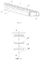
Fig. 3 is a perspective view of the manifold according to the invention, with a part of the cover cut off along the line A-A ofFig. 4 , in order to show the through holes in the cover. -
Fig. 4 shows a cover of the manifold viewed from the side faced to tubes. -
Fig. 5 is an exploded perspective view from one side of a heat exchanger with manifolds according to the invention. - As shown in
Figs. 1-4 themanifold 1 according to the invention is adapted to attach theflat tubes 17 to it for conducting the cooling medium, to form theheat exchanger 19, in particular an automotive radiator, such as shown inFig. 5 and discussed hereinafter. - Each
manifold 1 comprises ahousing 4 and acover 2, as shown in particular inFig. 2 . - The
cover 2 is manufactured as one part of a metal sheet, preferably of aluminium or its alloys, having thickness 0.8 mm to 2 mm, more preferably 1 mm, by means of the stamping process in such manner that it substantially replicates an external shape of thehousing 4. Thecover 2 can be subjected to cladding with an alloy of lower melting point relative to the melting point of the substrate material (e.g. AISi alloy) on one or both sides in order to facilitate brazing. Thecover 2 hasplurality slots 3 formed in one row and parallel to each other for receivingflat tubes 17 when themanifold 1 is used in theheat exchanger 19, saidflat tubes 17 of theheat exchanger 19 are introduced, between which theribs 18 are extended. Theslots 3 are precisely matched to the dimensions of theflat tubes 17 and tightly receive thetubes 17. - The
housing 4 has a closed hollow profile, it is an one-piece element manufactured using an extrusion process, it has thick and solid walls resulting in its resistance to high operational pressure and it contains at least onechannel 5 in its interior at for the flow of a cooling medium. In the illustrated embodiment thehousing 4 comprises two separatelongitudinal channels arch 7 in order to strengthen the structure of thehousing 4 and theentire manifold 1. Thehousing 4 is also provided in its interior, i.e. oninternal surfaces channels flat tubes 17 abut. The stopping elements 8 can have a form of projections extending along thechannels surfaces channels housing 4 has plurality ofslots 10 at positions corresponding to the positions of theslots 3 in thecover 2, wherein theslots 10 need not be made with such accurate dimensions as theslots 3 of thecover 2, that is, their dimensions did not have to be exactly matched to the dimensions of theflat tubes 17, but it is sufficient that theslots 10 will have a size at least the same or larger than the size of theflat tubes 17, and hence also theslots 3. This results in that theflat tubes 17 are received loosely into theslots 10 and tightly into theslots 3. Like thecover 2, thehousing 4 is also preferably made of aluminium or its alloys. - Referring particularly to
Figs. 2 ,3 and5 , it can be noted that thecover 2 is laid and bent over thehousing 4, in particular over its corners 9, so that, preferably, a larger portion of one of the outer surfaces of thehousing 4, opposite to the surface on which theslots 10 are made, remains an exposedsurface 12. It is sufficient that thecover 2 will cover at least a surface of thehousing 4, in which theslots 10 are arranged. Thecover 2 can protrude longitudinally beyond theends 14 of thehousing 4, so as to form aseat 15 for aplug 16, preferably made of aluminium or its alloys, for sealing the ends of thechannels entire manifold 1. In another embodiment (not shown) the plug can abut against the cover and the housing together. - As shown in
Figs. 1 and5 , in use of themanifold 1 according to the invention in theheat exchanger 19, theflat tubes 17 are inserted into theslots manifold 1, that is into thecover 2 and thehousing 4. Thetubes 17 are firstly received tightly into theslots 3 and next loosely into theslots 10 and abut against the stopping elements 8 in thehousing 4 with the result that their further inward movement into thehousing 4 is stopped and their position in the housing is fixed. This also results in that the outlets/inlets of theflat tubes 17 will not be blocked/closed by thesurfaces channels flat tubes 17 are secured to and sealed against themanifold 1 by brazing between theflat tube 17 and thecover 2, i.e. around theslots 3. - The
cover 2 and thehousing 4 are also joined together and sealed against each other by brazing in a brazing furnace. The aim of such connection is the sealing of all contact edges between thecover 2 and thehousing 4. However, the brazing of the two relatively large surfaces, such as surfaces of thecover 2 and thehousing 4, can lead to brazing defects in the form of gaps, which will result in leakage of the cooling medium out thehousing 2 through the areas around thetubes 17 mounted loosely in theslots 10 and through said gaps in the brazed connection. - Detection of defects of brazed connection between the
cover 2 and thehousing 4, leading to weakening the structure, leakages at the manufacturing stage of heat exchangers and during operation, is very important because the pressure of the cooling medium in the manifold is up 17 MPa, and even small brazing defects and small leakages cause the loss of functionality of the heat exchanger at end-users. - In order to enable easy detection such defects during the manufacture of the heat exchanger the
cover 2 according to the invention is provided with a number of throughholes 20 as shown inFigs. 3 and 4 , for detecting the leakage of the cooling medium. The throughholes 20 are formed in the areas of thecover 2 between itsslots 3 for seating of thetubes 17. In particular, thethrough holes 20 are preferably cylindrical and are arranged along the plane of symmetry of thecover 2 as shown inFigs. 1 ,3 and 4 , but there are also other possible cross-sections of those through holes and their location out of the plane of symmetry of thecover 2. While in the drawings one through hole is located between each twoadjacent slots 3, other arrangements of the slots are possible. If in a brazed connection of thecover 2 and the housing 4 a defect in the form of a gap, which causes the leakage of a cooling medium into the space between thecover 2 and thehousing 4, occurs it is possible to easily observe and locate the presence of that cooling medium in that intermediate space from outside of thecover 2 due to the leakage of that cooling medium through the throughhole 20 that is located closest to that gap. Thanks to that it is possible quick and reliable detecting of the heat exchanger having that defective manifold, to eliminate it from further production process and application in other complex products. - The through
holes 20 are formed in a known cheap and easy way through cutting them by a punching tool in a stamping process of thehousing 2. -
Fig. 5 shows the heat exchanger, in which manifolds 1 according to the invention are used. In the illustrated embodiment twoseparate manifolds 1 are arranged on the right side of theheat exchanger 19, wherein one of them is used for supplying the cooling medium into the heat exchanger, while the other is for discharging that medium. Thesemanifolds 1 are provided withports 13 on their exposedsurfaces 12, uncovered by thecover 2, for connection to an external circuit of a cooling medium. Theports 13 are in fluid communication with the channels of thehousing 4. Themanifold 1 shown inFig. 5 on the left side of theheat exchanger 19 is not provided with such ports, therefore it is only an intermediate element in theheat exchanger 19, i.e. the cooling medium enters through one of themanifolds 1 on the right side of the heat exchanger, flows through a part of the flat tubes, flows into themanifold 1 on the left side of the heat exchanger, re-enters later into the second part of theflat tubes 17 and exits through the other of themanifolds 1 on the right side of theheat exchanger 19. - In another embodiment (not shown) of the heat exchanger one manifold can be used on either side of it, each of which has a port, wherein one of the tubes is an inlet tube and the other is an outlet tube.
- Note that it is possible to exchange technical features between the above-described embodiments of the invention. It is possible to connect some manifolds in one longer manifold, wherein, in such a case, the manifolds without plugs are used which are firmly butt joined, and only then the ends of the extreme manifolds are closed with plugs.
Claims (12)
- A manifold (1) to a heat exchanger, in particular to an automotive radiator, comprising:a housing (4) which is an one-piece element having a closed profile and having at least one longitudinal channel (5) defined therein and also plurality of slots (10) located on one of the surfaces of said housing (4), wherein said slots (10) are in fluid communication to said at least one longitudinal channel (5); anda cover (2) laid on said housing (4) and having plurality of slots (3) at positions corresponding to the positions of said slots (10) of said housing (4) for receiving tubes (17) of the heat exchanger (19), wherein said cover (2) is connected to said housing (4) by a brazing connection;characterized in that:said cover (2) is provided with a number of through holes (20) for detecting leakage of the cooling medium through a brazed connection between said cover (2) and the housing (4), wherein said through holes (20) are formed in areas of the cover (2) between the slots (3).
- The manifold (1) according to Claim 1, characterized in that said through holes (20) are arranged along the plane of symmetry of the cover (2).
- The manifold (1) according to Claim 1 or 2, characterized in that said through holes (20) are cylindrical and have diameter in a range from 0.5 to4mm.
- The manifold according to any one of the preceding Claims, characterized in that said cover (2) and said housing (4) are made of aluminium or its alloys and are connected by means of brazing to each other.
- The manifold according to any one of the preceding Claims, characterized in that said cover (2) comprises a cladded layer of an alloy having a lower melting point relative to the melting point of the substrate material deposited on at least one surface thereof.
- The manifold (1) according to any one of the preceding claims, characterized in that said cover (2) has thickness in a range from 0.8 to 2 mm.
- The manifold according to any one of the preceding claims, characterized in that the size of said slots (3) of said cover (2) is at least equal to or greater than the size of said slots (10) of said housing (4) .
- The manifold according to any one of the preceding claims, characterized in that said at least one longitudinal channel (5) comprises two channels (5a, 5b) separated by a reinforcement arch (7), wherein each said channel (5a, 5b) has its own stopping element (8) on its inner surface (6a, 6b) for positioning ends of the tubes (17) in the housing (4).
- The manifold according to any one of the preceding claims, characterized in that one surface (12) of said housing (4) is exposed and comprises at least one port (13), which is in fluid communication to said at least one longitudinal channel (5), for connection to an external circuit of the cooling medium circuit.
- The manifold according to any one of the preceding claims, characterized in that it is closed at both of its ends by a plug (16).
- The manifold according to Claim 8, characterized in that said plug (16) is made of aluminium or its alloys and is connected to said cover (2) and said housing (4) by means of brazing.
- A heat exchanger (19), in particular an automotive radiator, comprising the manifold (1) according to any one of Claims 1-12.
Priority Applications (1)
| Application Number | Priority Date | Filing Date | Title |
|---|---|---|---|
| EP16170581.9A EP3246650B1 (en) | 2016-05-20 | 2016-05-20 | A manifold for a heat exchanger, in particular for an automotive radiator |
Applications Claiming Priority (1)
| Application Number | Priority Date | Filing Date | Title |
|---|---|---|---|
| EP16170581.9A EP3246650B1 (en) | 2016-05-20 | 2016-05-20 | A manifold for a heat exchanger, in particular for an automotive radiator |
Publications (2)
| Publication Number | Publication Date |
|---|---|
| EP3246650A1 true EP3246650A1 (en) | 2017-11-22 |
| EP3246650B1 EP3246650B1 (en) | 2018-12-19 |
Family
ID=56072242
Family Applications (1)
| Application Number | Title | Priority Date | Filing Date |
|---|---|---|---|
| EP16170581.9A Active EP3246650B1 (en) | 2016-05-20 | 2016-05-20 | A manifold for a heat exchanger, in particular for an automotive radiator |
Country Status (1)
| Country | Link |
|---|---|
| EP (1) | EP3246650B1 (en) |
Citations (4)
| Publication number | Priority date | Publication date | Assignee | Title |
|---|---|---|---|---|
| JPH04292793A (en) * | 1991-03-20 | 1992-10-16 | Zexel Corp | Heat exchanger |
| US20020036078A1 (en) * | 2000-09-28 | 2002-03-28 | Janezich Robert J. | Heat exchanger seal apparatus |
| US20060021746A1 (en) * | 2004-07-31 | 2006-02-02 | Valeo, Inc. | Heat exchanger having a double baffle |
| EP2960609A1 (en) | 2014-06-26 | 2015-12-30 | Valeo Autosystemy SP. Z.O.O. | Manifold, in particular for use in a cooler of a cooling system |
-
2016
- 2016-05-20 EP EP16170581.9A patent/EP3246650B1/en active Active
Patent Citations (4)
| Publication number | Priority date | Publication date | Assignee | Title |
|---|---|---|---|---|
| JPH04292793A (en) * | 1991-03-20 | 1992-10-16 | Zexel Corp | Heat exchanger |
| US20020036078A1 (en) * | 2000-09-28 | 2002-03-28 | Janezich Robert J. | Heat exchanger seal apparatus |
| US20060021746A1 (en) * | 2004-07-31 | 2006-02-02 | Valeo, Inc. | Heat exchanger having a double baffle |
| EP2960609A1 (en) | 2014-06-26 | 2015-12-30 | Valeo Autosystemy SP. Z.O.O. | Manifold, in particular for use in a cooler of a cooling system |
Also Published As
| Publication number | Publication date |
|---|---|
| EP3246650B1 (en) | 2018-12-19 |
Similar Documents
| Publication | Publication Date | Title |
|---|---|---|
| EP2435774B1 (en) | Double-walled plate heat exchanger | |
| JP4797998B2 (en) | Heat exchanger piping joint structure and heat exchanger piping assembly method | |
| US20180003448A1 (en) | Connecting member and micro-channel heat exchanger | |
| US20150369413A1 (en) | Double wall tube bolted flange fitting | |
| US8052174B2 (en) | Pipe joint design | |
| US20140352934A1 (en) | Plate heat exchanger | |
| WO2019176565A1 (en) | Plate-type heat exchanger, heat pump device comprising plate-type heat exchanger, and heat pump-type heating/cooling hot water supply system comprising heat pump device | |
| US20160025419A1 (en) | Plate heat exchanger and method for constructing multiple passes in the plate heat exchanger | |
| US20150377560A1 (en) | Manifold, in particular for use in a cooler of a cooling system | |
| CN102483308A (en) | Heat exchanger | |
| KR20090020616A (en) | Plumbing connector for heat exchanger | |
| KR20010090844A (en) | Baffle for heat exchanger and installation method thereof | |
| JP5646133B2 (en) | Heat exchanger with double baffle | |
| KR101359778B1 (en) | Welding method for shell and tube | |
| US10386125B2 (en) | Heat exchanger having fitting assembly | |
| EP4365514A1 (en) | Pipeline device and refrigeration system having same | |
| EP3246650B1 (en) | A manifold for a heat exchanger, in particular for an automotive radiator | |
| CN112033185B (en) | Header box and heat exchanger | |
| US20080073068A1 (en) | Radiator | |
| EP3252421B1 (en) | Heat exchanger assembly | |
| SE518971C2 (en) | Feeding device for a plate heat exchanger, plate heat exchanger and method for manufacturing such a | |
| JPH05157486A (en) | Heat exchanger | |
| JP6263922B2 (en) | Heat exchanger | |
| JP6432753B2 (en) | Heat exchanger and heat exchanger manufacturing method | |
| JP2009287907A (en) | Heat exchanger |
Legal Events
| Date | Code | Title | Description |
|---|---|---|---|
| PUAI | Public reference made under article 153(3) epc to a published international application that has entered the european phase |
Free format text: ORIGINAL CODE: 0009012 |
|
| STAA | Information on the status of an ep patent application or granted ep patent |
Free format text: STATUS: THE APPLICATION HAS BEEN PUBLISHED |
|
| AK | Designated contracting states |
Kind code of ref document: A1 Designated state(s): AL AT BE BG CH CY CZ DE DK EE ES FI FR GB GR HR HU IE IS IT LI LT LU LV MC MK MT NL NO PL PT RO RS SE SI SK SM TR |
|
| AX | Request for extension of the european patent |
Extension state: BA ME |
|
| STAA | Information on the status of an ep patent application or granted ep patent |
Free format text: STATUS: REQUEST FOR EXAMINATION WAS MADE |
|
| 17P | Request for examination filed |
Effective date: 20180522 |
|
| RBV | Designated contracting states (corrected) |
Designated state(s): AL AT BE BG CH CY CZ DE DK EE ES FI FR GB GR HR HU IE IS IT LI LT LU LV MC MK MT NL NO PL PT RO RS SE SI SK SM TR |
|
| GRAP | Despatch of communication of intention to grant a patent |
Free format text: ORIGINAL CODE: EPIDOSNIGR1 |
|
| STAA | Information on the status of an ep patent application or granted ep patent |
Free format text: STATUS: GRANT OF PATENT IS INTENDED |
|
| RIC1 | Information provided on ipc code assigned before grant |
Ipc: F28F 9/02 20060101AFI20180612BHEP |
|
| INTG | Intention to grant announced |
Effective date: 20180705 |
|
| GRAS | Grant fee paid |
Free format text: ORIGINAL CODE: EPIDOSNIGR3 |
|
| GRAA | (expected) grant |
Free format text: ORIGINAL CODE: 0009210 |
|
| STAA | Information on the status of an ep patent application or granted ep patent |
Free format text: STATUS: THE PATENT HAS BEEN GRANTED |
|
| AK | Designated contracting states |
Kind code of ref document: B1 Designated state(s): AL AT BE BG CH CY CZ DE DK EE ES FI FR GB GR HR HU IE IS IT LI LT LU LV MC MK MT NL NO PL PT RO RS SE SI SK SM TR |
|
| REG | Reference to a national code |
Ref country code: GB Ref legal event code: FG4D |
|
| REG | Reference to a national code |
Ref country code: CH Ref legal event code: EP |
|
| REG | Reference to a national code |
Ref country code: IE Ref legal event code: FG4D |
|
| REG | Reference to a national code |
Ref country code: DE Ref legal event code: R096 Ref document number: 602016008348 Country of ref document: DE |
|
| REG | Reference to a national code |
Ref country code: AT Ref legal event code: REF Ref document number: 1079189 Country of ref document: AT Kind code of ref document: T Effective date: 20190115 |
|
| REG | Reference to a national code |
Ref country code: NL Ref legal event code: MP Effective date: 20181219 |
|
| PG25 | Lapsed in a contracting state [announced via postgrant information from national office to epo] |
Ref country code: FI Free format text: LAPSE BECAUSE OF FAILURE TO SUBMIT A TRANSLATION OF THE DESCRIPTION OR TO PAY THE FEE WITHIN THE PRESCRIBED TIME-LIMIT Effective date: 20181219 Ref country code: LV Free format text: LAPSE BECAUSE OF FAILURE TO SUBMIT A TRANSLATION OF THE DESCRIPTION OR TO PAY THE FEE WITHIN THE PRESCRIBED TIME-LIMIT Effective date: 20181219 Ref country code: HR Free format text: LAPSE BECAUSE OF FAILURE TO SUBMIT A TRANSLATION OF THE DESCRIPTION OR TO PAY THE FEE WITHIN THE PRESCRIBED TIME-LIMIT Effective date: 20181219 Ref country code: BG Free format text: LAPSE BECAUSE OF FAILURE TO SUBMIT A TRANSLATION OF THE DESCRIPTION OR TO PAY THE FEE WITHIN THE PRESCRIBED TIME-LIMIT Effective date: 20190319 Ref country code: LT Free format text: LAPSE BECAUSE OF FAILURE TO SUBMIT A TRANSLATION OF THE DESCRIPTION OR TO PAY THE FEE WITHIN THE PRESCRIBED TIME-LIMIT Effective date: 20181219 Ref country code: NO Free format text: LAPSE BECAUSE OF FAILURE TO SUBMIT A TRANSLATION OF THE DESCRIPTION OR TO PAY THE FEE WITHIN THE PRESCRIBED TIME-LIMIT Effective date: 20190319 |
|
| REG | Reference to a national code |
Ref country code: LT Ref legal event code: MG4D |
|
| REG | Reference to a national code |
Ref country code: AT Ref legal event code: MK05 Ref document number: 1079189 Country of ref document: AT Kind code of ref document: T Effective date: 20181219 |
|
| PG25 | Lapsed in a contracting state [announced via postgrant information from national office to epo] |
Ref country code: GR Free format text: LAPSE BECAUSE OF FAILURE TO SUBMIT A TRANSLATION OF THE DESCRIPTION OR TO PAY THE FEE WITHIN THE PRESCRIBED TIME-LIMIT Effective date: 20190320 Ref country code: RS Free format text: LAPSE BECAUSE OF FAILURE TO SUBMIT A TRANSLATION OF THE DESCRIPTION OR TO PAY THE FEE WITHIN THE PRESCRIBED TIME-LIMIT Effective date: 20181219 Ref country code: SE Free format text: LAPSE BECAUSE OF FAILURE TO SUBMIT A TRANSLATION OF THE DESCRIPTION OR TO PAY THE FEE WITHIN THE PRESCRIBED TIME-LIMIT Effective date: 20181219 Ref country code: AL Free format text: LAPSE BECAUSE OF FAILURE TO SUBMIT A TRANSLATION OF THE DESCRIPTION OR TO PAY THE FEE WITHIN THE PRESCRIBED TIME-LIMIT Effective date: 20181219 |
|
| PG25 | Lapsed in a contracting state [announced via postgrant information from national office to epo] |
Ref country code: NL Free format text: LAPSE BECAUSE OF FAILURE TO SUBMIT A TRANSLATION OF THE DESCRIPTION OR TO PAY THE FEE WITHIN THE PRESCRIBED TIME-LIMIT Effective date: 20181219 |
|
| PG25 | Lapsed in a contracting state [announced via postgrant information from national office to epo] |
Ref country code: CZ Free format text: LAPSE BECAUSE OF FAILURE TO SUBMIT A TRANSLATION OF THE DESCRIPTION OR TO PAY THE FEE WITHIN THE PRESCRIBED TIME-LIMIT Effective date: 20181219 Ref country code: IT Free format text: LAPSE BECAUSE OF FAILURE TO SUBMIT A TRANSLATION OF THE DESCRIPTION OR TO PAY THE FEE WITHIN THE PRESCRIBED TIME-LIMIT Effective date: 20181219 Ref country code: ES Free format text: LAPSE BECAUSE OF FAILURE TO SUBMIT A TRANSLATION OF THE DESCRIPTION OR TO PAY THE FEE WITHIN THE PRESCRIBED TIME-LIMIT Effective date: 20181219 Ref country code: PT Free format text: LAPSE BECAUSE OF FAILURE TO SUBMIT A TRANSLATION OF THE DESCRIPTION OR TO PAY THE FEE WITHIN THE PRESCRIBED TIME-LIMIT Effective date: 20190419 Ref country code: PL Free format text: LAPSE BECAUSE OF FAILURE TO SUBMIT A TRANSLATION OF THE DESCRIPTION OR TO PAY THE FEE WITHIN THE PRESCRIBED TIME-LIMIT Effective date: 20181219 |
|
| PG25 | Lapsed in a contracting state [announced via postgrant information from national office to epo] |
Ref country code: SM Free format text: LAPSE BECAUSE OF FAILURE TO SUBMIT A TRANSLATION OF THE DESCRIPTION OR TO PAY THE FEE WITHIN THE PRESCRIBED TIME-LIMIT Effective date: 20181219 Ref country code: EE Free format text: LAPSE BECAUSE OF FAILURE TO SUBMIT A TRANSLATION OF THE DESCRIPTION OR TO PAY THE FEE WITHIN THE PRESCRIBED TIME-LIMIT Effective date: 20181219 Ref country code: SK Free format text: LAPSE BECAUSE OF FAILURE TO SUBMIT A TRANSLATION OF THE DESCRIPTION OR TO PAY THE FEE WITHIN THE PRESCRIBED TIME-LIMIT Effective date: 20181219 Ref country code: IS Free format text: LAPSE BECAUSE OF FAILURE TO SUBMIT A TRANSLATION OF THE DESCRIPTION OR TO PAY THE FEE WITHIN THE PRESCRIBED TIME-LIMIT Effective date: 20190419 Ref country code: RO Free format text: LAPSE BECAUSE OF FAILURE TO SUBMIT A TRANSLATION OF THE DESCRIPTION OR TO PAY THE FEE WITHIN THE PRESCRIBED TIME-LIMIT Effective date: 20181219 |
|
| REG | Reference to a national code |
Ref country code: DE Ref legal event code: R097 Ref document number: 602016008348 Country of ref document: DE |
|
| PLBE | No opposition filed within time limit |
Free format text: ORIGINAL CODE: 0009261 |
|
| STAA | Information on the status of an ep patent application or granted ep patent |
Free format text: STATUS: NO OPPOSITION FILED WITHIN TIME LIMIT |
|
| PG25 | Lapsed in a contracting state [announced via postgrant information from national office to epo] |
Ref country code: DK Free format text: LAPSE BECAUSE OF FAILURE TO SUBMIT A TRANSLATION OF THE DESCRIPTION OR TO PAY THE FEE WITHIN THE PRESCRIBED TIME-LIMIT Effective date: 20181219 Ref country code: AT Free format text: LAPSE BECAUSE OF FAILURE TO SUBMIT A TRANSLATION OF THE DESCRIPTION OR TO PAY THE FEE WITHIN THE PRESCRIBED TIME-LIMIT Effective date: 20181219 |
|
| 26N | No opposition filed |
Effective date: 20190920 |
|
| REG | Reference to a national code |
Ref country code: CH Ref legal event code: PL |
|
| PG25 | Lapsed in a contracting state [announced via postgrant information from national office to epo] |
Ref country code: CH Free format text: LAPSE BECAUSE OF NON-PAYMENT OF DUE FEES Effective date: 20190531 Ref country code: MC Free format text: LAPSE BECAUSE OF FAILURE TO SUBMIT A TRANSLATION OF THE DESCRIPTION OR TO PAY THE FEE WITHIN THE PRESCRIBED TIME-LIMIT Effective date: 20181219 Ref country code: LI Free format text: LAPSE BECAUSE OF NON-PAYMENT OF DUE FEES Effective date: 20190531 |
|
| REG | Reference to a national code |
Ref country code: BE Ref legal event code: MM Effective date: 20190531 |
|
| PG25 | Lapsed in a contracting state [announced via postgrant information from national office to epo] |
Ref country code: SI Free format text: LAPSE BECAUSE OF FAILURE TO SUBMIT A TRANSLATION OF THE DESCRIPTION OR TO PAY THE FEE WITHIN THE PRESCRIBED TIME-LIMIT Effective date: 20181219 Ref country code: LU Free format text: LAPSE BECAUSE OF NON-PAYMENT OF DUE FEES Effective date: 20190520 |
|
| PG25 | Lapsed in a contracting state [announced via postgrant information from national office to epo] |
Ref country code: TR Free format text: LAPSE BECAUSE OF FAILURE TO SUBMIT A TRANSLATION OF THE DESCRIPTION OR TO PAY THE FEE WITHIN THE PRESCRIBED TIME-LIMIT Effective date: 20181219 |
|
| PG25 | Lapsed in a contracting state [announced via postgrant information from national office to epo] |
Ref country code: IE Free format text: LAPSE BECAUSE OF NON-PAYMENT OF DUE FEES Effective date: 20190520 |
|
| PG25 | Lapsed in a contracting state [announced via postgrant information from national office to epo] |
Ref country code: BE Free format text: LAPSE BECAUSE OF NON-PAYMENT OF DUE FEES Effective date: 20190531 |
|
| GBPC | Gb: european patent ceased through non-payment of renewal fee |
Effective date: 20200520 |
|
| PG25 | Lapsed in a contracting state [announced via postgrant information from national office to epo] |
Ref country code: GB Free format text: LAPSE BECAUSE OF NON-PAYMENT OF DUE FEES Effective date: 20200520 |
|
| PG25 | Lapsed in a contracting state [announced via postgrant information from national office to epo] |
Ref country code: CY Free format text: LAPSE BECAUSE OF FAILURE TO SUBMIT A TRANSLATION OF THE DESCRIPTION OR TO PAY THE FEE WITHIN THE PRESCRIBED TIME-LIMIT Effective date: 20181219 |
|
| PG25 | Lapsed in a contracting state [announced via postgrant information from national office to epo] |
Ref country code: HU Free format text: LAPSE BECAUSE OF FAILURE TO SUBMIT A TRANSLATION OF THE DESCRIPTION OR TO PAY THE FEE WITHIN THE PRESCRIBED TIME-LIMIT; INVALID AB INITIO Effective date: 20160520 Ref country code: MT Free format text: LAPSE BECAUSE OF FAILURE TO SUBMIT A TRANSLATION OF THE DESCRIPTION OR TO PAY THE FEE WITHIN THE PRESCRIBED TIME-LIMIT Effective date: 20181219 |
|
| PG25 | Lapsed in a contracting state [announced via postgrant information from national office to epo] |
Ref country code: MK Free format text: LAPSE BECAUSE OF FAILURE TO SUBMIT A TRANSLATION OF THE DESCRIPTION OR TO PAY THE FEE WITHIN THE PRESCRIBED TIME-LIMIT Effective date: 20181219 |
|
| P01 | Opt-out of the competence of the unified patent court (upc) registered |
Effective date: 20230528 |
|
| PGFP | Annual fee paid to national office [announced via postgrant information from national office to epo] |
Ref country code: DE Payment date: 20250513 Year of fee payment: 10 |
|
| PGFP | Annual fee paid to national office [announced via postgrant information from national office to epo] |
Ref country code: FR Payment date: 20250530 Year of fee payment: 10 |