EP3246632A1 - Domestic appliance and door for a domestic appliance - Google Patents
Domestic appliance and door for a domestic appliance Download PDFInfo
- Publication number
- EP3246632A1 EP3246632A1 EP16170393.9A EP16170393A EP3246632A1 EP 3246632 A1 EP3246632 A1 EP 3246632A1 EP 16170393 A EP16170393 A EP 16170393A EP 3246632 A1 EP3246632 A1 EP 3246632A1
- Authority
- EP
- European Patent Office
- Prior art keywords
- door
- domestic appliance
- front panel
- door handle
- appliance according
- Prior art date
- Legal status (The legal status is an assumption and is not a legal conclusion. Google has not performed a legal analysis and makes no representation as to the accuracy of the status listed.)
- Granted
Links
Images

Classifications
-
- F—MECHANICAL ENGINEERING; LIGHTING; HEATING; WEAPONS; BLASTING
- F24—HEATING; RANGES; VENTILATING
- F24C—DOMESTIC STOVES OR RANGES ; DETAILS OF DOMESTIC STOVES OR RANGES, OF GENERAL APPLICATION
- F24C15/00—Details
- F24C15/02—Doors specially adapted for stoves or ranges
- F24C15/024—Handles
Definitions
- the present invention relates to a door for a domestic appliance. Further, the present invention relates to a domestic appliance. In particular, the present invention relates to an oven door for a cooking oven and a corresponding cooking oven.
- An electrostatic discharge is the transfer of charge between objects at different electrical potential.
- An electrostatic discharge accident may occur, if any charged conductor, e.g. also the human body, discharges to an electrostatic discharge sensitive device, or if said electrostatic discharge sensitive device discharges to packaging materials or to a human body. For example, people walking along a carpeted room or sitting in a car generate sufficient static electricity.
- the electrostatic discharge sensitive device may be placed in or at a door handle of a domestic appliance. If a human being walks along a carpeted room, then the human body may built up an electric potential of several thousand volts. Said electric potential may cause an electrostatic discharge, if the fingers are close to the door handle. When the human body feels a shock, the electrostatic discharge potential is about thousands of volts.
- the electronic components in a power module can be damaged by discharges of much lower voltage. In other words, the damage of the electronic components may occur even if the electrostatic discharge shock is not felt.
- the electrostatic discharge is one of the leading causes of failure in power modules and integrated circuits. Over the years, electronic devices have become faster and smaller, so that their electrostatic discharge sensitivity has been increased. Commonly, everyday objects used in or close to the working place, such a Styrofoam coffee cups, flooring materials, storage bins, desktops and even ordinary clothes are all sources of static electricity.
- the object is achieved by the domestic appliance according to claim 1, and a door according to claim 15.
- each feature and each combination of features in the embodiments as described herein may for example be claimed in a different combination, in particular different claim category, at least because the skilled person will recognize that each and every combination of the features mentioned herein is suitable for contributing to solving the underlying problem.
- a door according to the present invention particularly for a domestic appliance according to the present invention, more particularly an oven door for a cooking oven, respectively, is provided.
- a door according to the present invention comprises
- At least one conducting element is attached at the inner side and/or outer side of the front panel,
- the core of the present invention is that the door handle is grounded via the fastening element, the conducting element, the terminal lug and the grounding element.
- each of said fastening element, the conducting element, the terminal lug and the grounding element is made of a conducting material, preferably a conducting metal or metal alloy.
- the fastening element causes the grounding of the door handle.
- the door handle may be disassembled from the front panel, e.g. for cleaning purposes, without disconnecting the grounding element.
- the grounding of the door handle is realized by low complexity and low costs.
- the grounding concept of the present invention is very robust. Moreover, the grounding concept is independent from the power supply concept of the oven door and from the design of the door handle. At last, the grounding concept is independent from the structure and the properties of the electronic device.
- lateral or “laterally”, “rear”, “frontal”, “upper”, “lower”, “bottom”, “opposite”, “inner”, “outer” or the like, as used herein, which describe the position of a first object relative to another object, preferably refer to the relative position of a respective part or object with regard to its position fully mounted for its intended use.
- the grounding element preferably is a grounding wire or grounding stripe, more preferably a grounding wire.
- the door comprises a doorframe or a pair of door columns, wherein the doorframe or door columns, respectively, are attached at an inner side of the front panel.
- the fastening element may penetrate into the doorframe or door column, respectively, so that the fastening element and the door handle are supported by the door frame or door column, respectively.
- the fastening element preferably is an elongate element, particularly a screw or pin, most preferably a screw.
- the fastening element is preferably made from an electrically conducting material, more preferably electrically conducting metal or conducting metal alloy.
- the conducting element may include a receiving, particularly a hole for receiving the fastening element.
- the conducting element may comprise a hole with an internal thread, wherein an external thread of the fastening element engages the internal thread of the conducting element. This guarantees an electric conductivity between the conducting element and the fastening element.
- the conducting element is glued at the inner side and/or outer side of the front panel, wherein the fastening element and the door handle are supported by the conducting element.
- the door handle may be an elongated hollow cylinder made of metal, in particular made of aluminium.
- the door comprises at least one adapter arranged between the door handle and the outer side of the front panel, wherein preferably the fastening element penetrates said adapter.
- the adapter acts as a spacer between the door handle and the outer side of the front panel.
- the door comprises power supply wires interconnected between the electric and/or electronic device and the chassis of the domestic appliance, wherein a portion of said power supply wires extends inside the door handle.
- a further portion of the power supply wires extends inside or at the doorframe or door column.
- At least a portion of the power supply wires and at least a portion of the grounding element form a multicore cable. This contributes to a compact structure of the door.
- the grounding element is arranged inside or at the doorframe or door column, respectively, of the door.
- the grounding element is directly connected or connectable to the chassis of the domestic appliance.
- the grounding element is connected or connectable to the chassis of the domestic appliance via a pogo spring connection.
- grounding element may be connected or connectable to the chassis of the domestic appliance via sliding contact stripes.
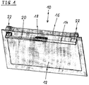
- FIG 1 illustrates a schematic perspective view of an oven door 10 including a protection device against electrostatic discharge according to a preferred embodiment of the present invention.
- the present invention relates to a door for an arbitrary domestic appliance, wherein said door includes the protection device.
- the oven door 10 comprises a front panel 12, a door handle 14 and a door frame 16.
- the door handle 14 is attached at an outer side of the front panel 12.
- the door frame 16 is attached at an inner side of the front panel 12.
- the door handle 14 is formed as an elongated hollow cylinder and extends horizontally.
- the door handle 14 is made of metal, preferably of aluminium.
- the door handle 14 is attached via two adapters 22 at the outer side of the front panel 12. Said adapters 22 act as spacers between the door handle 14 and the outer side of the front panel 12.
- An electronic device 18 is arranged at least partially within the door handle 14. In this example, a part of the electronic device 18 is arranged inside the door handle 14, while another part of the electronic device 18 is arranged out of the door handle 14 and between the front panel 12 and said door handle 14.
- the electronic device 18 is electrically insulated from the door handle 14.
- Power supply wires 20 are connected to the electronic device 18.
- the power supply wires 20 extend inside the door handle 14. The power supply wires 20 penetrate the adapter 22 and the front panel 12.
- further wires e.g. signal wires
- further wires may be connected to the electronic device 18, wherein said further wires extend inside the door handle 14 and penetrate the adapter 22 and the front panel 12.
- FIG 2 illustrates a detailed schematic perspective view of the oven door 10 including the protection device against electrostatic discharge according to the preferred embodiment of the present invention.
- FIG 2 shows an upper corner of the oven door 10. In FIG 2 only a vertical profile part of the door frame 16 is shown.
- the door handle 14 and the adapter 22 are attached at the outer side of the front panel 12 by a fastening element 24 , here a screw 24.
- Said screw 24 is made of metal and penetrates the door handle 14, the adapter 22, the front panel 12 and optionally the vertical profile part of the door frame 16.
- the screw 24 is connected to a conducting element 26, here a metal element 26, aligned at the inner side of the front panel 12.
- the metal element 26 is a washer.
- the metal element 26 is glued at the inner side of the front panel 12.
- the metal element 26 includes a hole with an internal thread, so that an external thread of the screw 24 engages the internal thread of the metal element 26.
- the screw 24 and the metal element 26 are galvanically connected to each other.
- the metal element 26 includes a terminal lug 32.
- a grounding element 30, here a grounding wire 30, is connected to the terminal lug 32 via a plug-in connection. Another end of said grounding wire 30 is connected to a chassis of a cooking oven.
- the door handle 14 is grounded via the screw 24, the metal element 26, the terminal lug 32 and the grounding wire 30. This grounding concept of the door handle 14 avoids electrostatic discharges.
- the door handle 14 and the screw 24 are supported by the metal element 26 or by the door frame 16, in particular by the vertical profile part of the door frame 16. Further, the door handle 14 and the screw 24 may be supported by both the metal element 26 and the door frame 16. If the door handle 14 and the screw 24 are supported by the door frame 16, then the metal element 26 may be also supported by the screw 24 and the door frame 16. In general, the metal element 26 is attached at the inner side or outer side of the front panel 12.
- the power supply wires 20 as well as the grounding wire 30 are arranged inside or at the vertical profile part of the door frame 16.
- the grounding wire 30 may be directly connected to the chassis of the cooking oven.
- grounding wire 30 may be connected to the chassis of the cooking oven via a grounding pogo spring element, if the power supply is realized by a pogo spring connection.
- the grounding wire 30 may be connected to the chassis of the cooking oven via sliding contact stripes. Said sliding contact stripes are often used for the power transfer between the chassis and the oven door 10.
- the present invention has the advantage that the grounding wire 30 does not have to be pushed through the hollow door handle 14. Further, it is not necessary to connect the grounding wire 30 directly to the door handle 14. No further grounding components are required, since the screw 24 supports the grounding of the door handle 14.
- the door handle 14 may be disassembled from the front panel 12, e.g. for cleaning purposes, without disconnecting the grounding wire 30.
- the grounding of the door handle 14 is realized by low complexity and low costs.
- the grounding concept according to the present invention is very robust. Moreover, the grounding concept is independent from the power supply concept of the oven door 10. The grounding concept is independent from the design of the door handle 14. Additionally, the grounding concept is independent from the structure and the properties of the electronic device 18.
- the electric insulation between the electronic device 18 and the door handle 14 on the one hand and the grounding concept of the present invention protects the electronic device 18 from damages by electrostatic discharge.
Landscapes
- Engineering & Computer Science (AREA)
- Chemical & Material Sciences (AREA)
- Combustion & Propulsion (AREA)
- Mechanical Engineering (AREA)
- General Engineering & Computer Science (AREA)
- Elimination Of Static Electricity (AREA)
- Electric Ovens (AREA)
Abstract
Description
- The present invention relates to a door for a domestic appliance. Further, the present invention relates to a domestic appliance. In particular, the present invention relates to an oven door for a cooking oven and a corresponding cooking oven.
- An electrostatic discharge is the transfer of charge between objects at different electrical potential. An electrostatic discharge accident may occur, if any charged conductor, e.g. also the human body, discharges to an electrostatic discharge sensitive device, or if said electrostatic discharge sensitive device discharges to packaging materials or to a human body. For example, people walking along a carpeted room or sitting in a car generate sufficient static electricity.
- Further, the electrostatic discharge sensitive device may be placed in or at a door handle of a domestic appliance. If a human being walks along a carpeted room, then the human body may built up an electric potential of several thousand volts. Said electric potential may cause an electrostatic discharge, if the fingers are close to the door handle. When the human body feels a shock, the electrostatic discharge potential is about thousands of volts. The electronic components in a power module can be damaged by discharges of much lower voltage. In other words, the damage of the electronic components may occur even if the electrostatic discharge shock is not felt. The electrostatic discharge is one of the leading causes of failure in power modules and integrated circuits. Over the years, electronic devices have become faster and smaller, so that their electrostatic discharge sensitivity has been increased. Commonly, everyday objects used in or close to the working place, such a Styrofoam coffee cups, flooring materials, storage bins, desktops and even ordinary clothes are all sources of static electricity.
- It is an object of the present invention to provide a door for a domestic appliance, wherein a door handle of said door is reliably grounded by low complexity.
- The object is achieved by the domestic appliance according to claim 1, and a door according to claim 15.
- Preferred embodiments may be taken from the dependent claims, and, beyond that, from the following description, in particular comprising various embodiments as covered and de-scribed in the annexed claims.
- The embodiments, features and combination of features as de-scribed herein in connection with the invention, as well as the combination of features as given in the annexed claims, but also any combination of features as mentioned and described in connection with the embodiments shall be considered as being disclosed herein, at least, however, shall be considered to be derivable by the skilled person.
- In particular, each feature and each combination of features in the embodiments as described herein may for example be claimed in a different combination, in particular different claim category, at least because the skilled person will recognize that each and every combination of the features mentioned herein is suitable for contributing to solving the underlying problem.
- According to the present invention a door according to the present invention, particularly for a domestic appliance according to the present invention, more particularly an oven door for a cooking oven, respectively, is provided.
- Thereby it is to be understood that each embodiment, feature, technical effect or advantage, which is described herein in connection with the domestic appliance, particularly oven, of the present invention, may also be an embodiment, feature, technical effect or advantage, respectively, of the door according to the present invention, and vice versa.
- A door according to the present invention, comprises
- a front panel,
- at least one door handle made of metal and arranged at an outer side of the front panel,
- at least one electric and/or electronic device arranged inside and/or at the door handle,
- at least one fastening element for fastening the door handle at the front panel.
- Moreover, at least one conducting element is attached at the
inner side and/or outer side of the front panel, - the fastening element penetrates the front panel and the conducting element,
- the conducting element includes a terminal lug connected or connectable to a grounding element, and
- the grounding element is connected or connectable to a chassis of the domestic appliance,
- so that the door handle is grounded via the fastening element, the conducting element, the terminal lug and the grounding element.
- The core of the present invention is that the door handle is grounded via the fastening element, the conducting element, the terminal lug and the grounding element. Particularly, each of said fastening element, the conducting element, the terminal lug and the grounding element is made of a conducting material, preferably a conducting metal or metal alloy. Thus, it is not necessary to connect the grounding element directly to the door handle. No further grounding components are required, since the fastening element causes the grounding of the door handle. Further, the door handle may be disassembled from the front panel, e.g. for cleaning purposes, without disconnecting the grounding element. The grounding of the door handle is realized by low complexity and low costs. The grounding concept of the present invention is very robust. Moreover, the grounding concept is independent from the power supply concept of the oven door and from the design of the door handle. At last, the grounding concept is independent from the structure and the properties of the electronic device.
- Within the present application, terms such as "lateral" or "laterally", "rear", "frontal", "upper", "lower", "bottom", "opposite", "inner", "outer" or the like, as used herein, which describe the position of a first object relative to another object, preferably refer to the relative position of a respective part or object with regard to its position fully mounted for its intended use.
- The grounding element preferably is a grounding wire or grounding stripe, more preferably a grounding wire.
- Preferably, the door comprises a doorframe or a pair of door columns, wherein the doorframe or door columns, respectively, are attached at an inner side of the front panel.
- In this case, the fastening element may penetrate into the doorframe or door column, respectively, so that the fastening element and the door handle are supported by the door frame or door column, respectively. The fastening element, preferably is an elongate element, particularly a screw or pin, most preferably a screw. Particularly, the fastening element is preferably made from an electrically conducting material, more preferably electrically conducting metal or conducting metal alloy.
- In particular, the conducting element may include a receiving, particularly a hole for receiving the fastening element. Particularly, the conducting element may comprise a hole with an internal thread, wherein an external thread of the fastening element engages the internal thread of the conducting element. This guarantees an electric conductivity between the conducting element and the fastening element.
- For example, the conducting element is glued at the inner side and/or outer side of the front panel, wherein the fastening element and the door handle are supported by the conducting element.
- Further, the door handle may be an elongated hollow cylinder made of metal, in particular made of aluminium.
- Preferably, the door comprises at least one adapter arranged between the door handle and the outer side of the front panel, wherein preferably the fastening element penetrates said adapter. The adapter acts as a spacer between the door handle and the outer side of the front panel.
- Furthermore, the door comprises power supply wires interconnected between the electric and/or electronic device and the chassis of the domestic appliance, wherein a portion of said power supply wires extends inside the door handle.
- For example, a further portion of the power supply wires extends inside or at the doorframe or door column.
- Preferably, at least a portion of the power supply wires and at least a portion of the grounding element form a multicore cable. This contributes to a compact structure of the door.
- In particular, the grounding element is arranged inside or at the doorframe or door column, respectively, of the door.
- For example, the grounding element is directly connected or connectable to the chassis of the domestic appliance.
- According to another example, the grounding element is connected or connectable to the chassis of the domestic appliance via a pogo spring connection.
- Furthermore, the grounding element may be connected or connectable to the chassis of the domestic appliance via sliding contact stripes.
- Novel and inventive features of the present invention are set forth in the appended claims.
- The present invention will be described in further detail with reference to the drawings from which further features, embodiments and advantages may be taken, and in which:
- FIG 1
- illustrates a schematic perspective view of an oven door including a protection device against electrostatic discharge according to a preferred embodiment of the present invention, and
- FIG 2
- illustrates a detailed schematic perspective view of the oven door including the protection device against electrostatic discharge according to the preferred embodiment of the present invention.
- In the embodiments shown in the figures, elements similar or identic in function are designated with like reference signs. It is noted, that the figures may not be true to scale with respect to each other.
-
FIG 1 illustrates a schematic perspective view of anoven door 10 including a protection device against electrostatic discharge according to a preferred embodiment of the present invention. In general, the present invention relates to a door for an arbitrary domestic appliance, wherein said door includes the protection device. - The
oven door 10 comprises afront panel 12, adoor handle 14 and adoor frame 16. Thedoor handle 14 is attached at an outer side of thefront panel 12. Thedoor frame 16 is attached at an inner side of thefront panel 12. Thedoor handle 14 is formed as an elongated hollow cylinder and extends horizontally. Thedoor handle 14 is made of metal, preferably of aluminium. Thedoor handle 14 is attached via twoadapters 22 at the outer side of thefront panel 12. Saidadapters 22 act as spacers between thedoor handle 14 and the outer side of thefront panel 12. - An
electronic device 18 is arranged at least partially within thedoor handle 14. In this example, a part of theelectronic device 18 is arranged inside thedoor handle 14, while another part of theelectronic device 18 is arranged out of thedoor handle 14 and between thefront panel 12 and saiddoor handle 14. Theelectronic device 18 is electrically insulated from thedoor handle 14.Power supply wires 20 are connected to theelectronic device 18. Thepower supply wires 20 extend inside thedoor handle 14. Thepower supply wires 20 penetrate theadapter 22 and thefront panel 12. - Optionally, further wires, e.g. signal wires, may be connected to the
electronic device 18, wherein said further wires extend inside thedoor handle 14 and penetrate theadapter 22 and thefront panel 12. -
FIG 2 illustrates a detailed schematic perspective view of theoven door 10 including the protection device against electrostatic discharge according to the preferred embodiment of the present invention.FIG 2 shows an upper corner of theoven door 10. InFIG 2 only a vertical profile part of thedoor frame 16 is shown. - The
door handle 14 and theadapter 22 are attached at the outer side of thefront panel 12 by afastening element 24 , here ascrew 24. Saidscrew 24 is made of metal and penetrates thedoor handle 14, theadapter 22, thefront panel 12 and optionally the vertical profile part of thedoor frame 16. Thescrew 24 is connected to a conductingelement 26, here ametal element 26, aligned at the inner side of thefront panel 12. In this example, themetal element 26 is a washer. For example, themetal element 26 is glued at the inner side of thefront panel 12. Preferably, themetal element 26 includes a hole with an internal thread, so that an external thread of thescrew 24 engages the internal thread of themetal element 26. Thus, thescrew 24 and themetal element 26 are galvanically connected to each other. Further, themetal element 26 includes aterminal lug 32. Agrounding element 30, here agrounding wire 30, is connected to theterminal lug 32 via a plug-in connection. Another end of saidgrounding wire 30 is connected to a chassis of a cooking oven. Thus, thedoor handle 14 is grounded via thescrew 24, themetal element 26, theterminal lug 32 and thegrounding wire 30. This grounding concept of thedoor handle 14 avoids electrostatic discharges. - The
door handle 14 and thescrew 24 are supported by themetal element 26 or by thedoor frame 16, in particular by the vertical profile part of thedoor frame 16. Further, thedoor handle 14 and thescrew 24 may be supported by both themetal element 26 and thedoor frame 16. If thedoor handle 14 and thescrew 24 are supported by thedoor frame 16, then themetal element 26 may be also supported by thescrew 24 and thedoor frame 16. In general, themetal element 26 is attached at the inner side or outer side of thefront panel 12. - In this example, the
power supply wires 20 as well as thegrounding wire 30 are arranged inside or at the vertical profile part of thedoor frame 16. Thegrounding wire 30 may be directly connected to the chassis of the cooking oven. Further, groundingwire 30 may be connected to the chassis of the cooking oven via a grounding pogo spring element, if the power supply is realized by a pogo spring connection. Moreover, thegrounding wire 30 may be connected to the chassis of the cooking oven via sliding contact stripes. Said sliding contact stripes are often used for the power transfer between the chassis and theoven door 10. - The present invention has the advantage that the
grounding wire 30 does not have to be pushed through thehollow door handle 14. Further, it is not necessary to connect thegrounding wire 30 directly to thedoor handle 14. No further grounding components are required, since thescrew 24 supports the grounding of thedoor handle 14. Thedoor handle 14 may be disassembled from thefront panel 12, e.g. for cleaning purposes, without disconnecting thegrounding wire 30. The grounding of thedoor handle 14 is realized by low complexity and low costs. The grounding concept according to the present invention is very robust. Moreover, the grounding concept is independent from the power supply concept of theoven door 10. The grounding concept is independent from the design of thedoor handle 14. Additionally, the grounding concept is independent from the structure and the properties of theelectronic device 18. - The electric insulation between the
electronic device 18 and thedoor handle 14 on the one hand and the grounding concept of the present invention protects theelectronic device 18 from damages by electrostatic discharge. - The embodiments in the figures may relate to preferred embodiments, while all elements and features described in connection with embodiments may be used, as far as appropriate, in combination with any other embodiment and feature as discussed herein, in particular related to any other embodiment discussed further above.
- Although an illustrative embodiment of the present invention has been described herein with reference to the accompanying drawings, it is to be understood that the present invention is not limited to that precise embodiment, and that various other changes and modifications may be affected therein by one skilled in the art without departing from the scope or spirit of the invention. All such changes and modifications are intended to be included within the scope of the invention as defined by the appended claims.
-
- 10
- oven door
- 12
- front panel
- 14
- door handle
- 16
- door frame
- 18
- electric device
- 20
- power supply wires
- 22
- adapter
- 24
- screw
- 26
- metal element
- 30
- grounding wire
- 32
- terminal lug
Claims (15)
- A domestic appliance, in particular a cooking oven, comprising a door (10) for the domestic appliance, in particular an oven door (10) for a cooking oven, wherein- the door (10) comprises a front panel (12),- the door (10) comprises at least one door handle (14) made of metal and arranged at an outer side of the front panel (12),- the door (10) comprises at least one electric and/or electronic device (18) arranged inside and/or at the door handle (14),- the door (10) comprises at least one fastening element (24) for fastening the door handle (14) at the front panel (12),- at least one conducting element (26) is attached at the inner side and/or outer side of the front panel (12),- the fastening element (24) penetrates the front panel (12) and the conducting element (26),- the conducting element (26) includes a terminal lug (32) connected or connectable to a grounding element (32), and- the grounding element (32) is connected or connectable to a chassis of the domestic appliance,- so that the door handle (14) is grounded via the fastening element (24), the conducting element (26), the terminal lug (32) and the grounding element (30).
- The domestic appliance according to claim 1, characterised in that the door (10) comprises a door frame (16) or a pair of door columns, wherein the door frame (16) or door columns, respectively, are attached at an inner side of the front panel (12).
- The domestic appliance according to claim 2, characterised in that the fastening element (24) penetrates into the door frame (16) or door column, respectively, so that the fastening element (24) and the door handle (14) are supported by the door frame (16) or door column, respectively.
- The domestic appliance according to any one of the preceding claims, characterised in that the conducting element (26) includes a hole with an internal thread, wherein an external thread of the fastening element (24) engages the internal thread of the conducting element (26).
- The domestic appliance according to any one of the preceding claims, characterised in that the conducting element (26) is glued at the inner side and/or outer side of the front panel (12), wherein the fastening element (24) and the door handle (14) are supported by the conducting element (26).
- The domestic appliance according to any one of the preceding claims, characterised in that the door handle (14) is an elongated hollow cylinder made of metal, in particular made of aluminium.
- The domestic appliance according to any one of the preceding claims, characterised in that the door (10) comprises at least one adapter (22) arranged between the door handle (14) and the outer side of the front panel (12), wherein preferably the fastening element (24) penetrates said adapter (22).
- The domestic appliance according to any one of the preceding claims, characterised in that the door (10) comprises power supply wires (20) interconnected between the electric and/or electronic device (18) and the chassis of the domestic appliance, wherein a portion of said power supply wires (20) extends inside the door handle (14).
- The domestic appliance according to claim 8, characterised in that a further portion of the power supply wires (20) extends inside or at the door frame (16) or door column.
- The domestic appliance according to claim 8 or 9, characterised in that at least a portion of the power supply wires (20) and at least a portion of the grounding element (32) form a multicore cable.
- The domestic appliance according to any one of the preceding claims, characterised in that the grounding element (32) is arranged inside or at the door frame (16) or door column, respectively, of the door (10).
- The domestic appliance according to any one of the preceding claims, characterised in that the grounding element (32) is directly connected or connectable to the chassis of the domestic appliance.
- The domestic appliance according to any one of the claims 1 to 11, characterised in that the grounding element (32) is connected or connectable to the chassis of the domestic appliance via a pogo spring connection.
- The domestic appliance according to any one of the claims 1 to 11, characterised in that the grounding element (32) is connected or connectable to the chassis of the domestic appliance via sliding contact stripes.
- A door (10) for a domestic appliance, in particular a cooking oven, characterised in that the door (10), particularly an oven door (10), is a door (10) for a domestic appliance according to any one of the claims 1 to 14.
Priority Applications (4)
| Application Number | Priority Date | Filing Date | Title |
|---|---|---|---|
| EP16170393.9A EP3246632B1 (en) | 2016-05-19 | 2016-05-19 | Domestic appliance comprising a door |
| AU2017267085A AU2017267085A1 (en) | 2016-05-19 | 2017-05-09 | Domestic appliance and door for a domestic appliance |
| US16/099,210 US10837650B2 (en) | 2016-05-19 | 2017-05-09 | Domestic appliance and door for a domestic appliance |
| PCT/EP2017/061091 WO2017198502A1 (en) | 2016-05-19 | 2017-05-09 | Domestic appliance and door for a domestic appliance |
Applications Claiming Priority (1)
| Application Number | Priority Date | Filing Date | Title |
|---|---|---|---|
| EP16170393.9A EP3246632B1 (en) | 2016-05-19 | 2016-05-19 | Domestic appliance comprising a door |
Publications (2)
| Publication Number | Publication Date |
|---|---|
| EP3246632A1 true EP3246632A1 (en) | 2017-11-22 |
| EP3246632B1 EP3246632B1 (en) | 2020-02-26 |
Family
ID=56083925
Family Applications (1)
| Application Number | Title | Priority Date | Filing Date |
|---|---|---|---|
| EP16170393.9A Active EP3246632B1 (en) | 2016-05-19 | 2016-05-19 | Domestic appliance comprising a door |
Country Status (4)
| Country | Link |
|---|---|
| US (1) | US10837650B2 (en) |
| EP (1) | EP3246632B1 (en) |
| AU (1) | AU2017267085A1 (en) |
| WO (1) | WO2017198502A1 (en) |
Cited By (2)
| Publication number | Priority date | Publication date | Assignee | Title |
|---|---|---|---|---|
| WO2020046150A1 (en) | 2018-08-29 | 2020-03-05 | Amica S.A. | Oven with a touch door handle |
| EP4180722A1 (en) * | 2021-11-15 | 2023-05-17 | Electrolux Appliances Aktiebolag | Household appliance door |
Families Citing this family (4)
| Publication number | Priority date | Publication date | Assignee | Title |
|---|---|---|---|---|
| USD1009590S1 (en) * | 2016-12-13 | 2024-01-02 | Whirlpool Corporation | Appliance door handle |
| USD953140S1 (en) * | 2016-12-28 | 2022-05-31 | Whirlpool Corporation | Handle |
| KR102940666B1 (en) * | 2021-04-28 | 2026-03-18 | 삼성전자주식회사 | Cooking apparatus |
| PL245733B1 (en) | 2021-06-24 | 2024-09-30 | Wala Spolka Z Ograniczona Odpowiedzialnoscia | Pipe holder with a closing mechanism for the control rod for the element closing the object's opening |
Citations (5)
| Publication number | Priority date | Publication date | Assignee | Title |
|---|---|---|---|---|
| US4489995A (en) * | 1981-08-14 | 1984-12-25 | Tyler Refrigeration Corporation | Adjustable electrical outlet assembly |
| US20050056046A1 (en) * | 2003-09-17 | 2005-03-17 | Lg Electronics Inc. | Leakage current interruption formation in refrigerator door |
| JP2009293845A (en) * | 2008-06-04 | 2009-12-17 | Sharp Corp | Drawer type heating cooker |
| WO2013126946A1 (en) * | 2012-02-27 | 2013-09-06 | Electrolux Home Products Pty Limited | Appliance lighting system |
| EP2868981A1 (en) * | 2013-10-31 | 2015-05-06 | Electrolux Appliances Aktiebolag | A door for a domestic appliance |
Family Cites Families (22)
| Publication number | Priority date | Publication date | Assignee | Title |
|---|---|---|---|---|
| US2778000A (en) * | 1952-06-14 | 1957-01-15 | Whirlpool Seeger Corp | Conductive hinge for refrigerator door |
| US3659063A (en) * | 1970-08-06 | 1972-04-25 | Hager & Sons Hinge Mfg | Hinge with means for conducting electricity therethrough |
| US4543800A (en) * | 1984-02-16 | 1985-10-01 | White Consolidated Industries, Inc. | Refrigerator door hinge |
| US5263509A (en) * | 1992-11-12 | 1993-11-23 | General Electric Company | Refrigerator with door mounted dispenser supply mechanism |
| US5632062A (en) * | 1993-07-22 | 1997-05-27 | General Electric Company | Handle assembly |
| US6185785B1 (en) * | 1999-09-28 | 2001-02-13 | The Coca-Cola Company | Bubbling bottle door handle |
| AU781858B2 (en) * | 1999-12-28 | 2005-06-16 | Lg Electronics Inc. | Door handle installation structure of refrigerator |
| IT250015Y1 (en) * | 2000-07-04 | 2003-07-07 | Whirlpool Co | DEVICE FOR ELECTRICALLY SUPPLYING USERS PRESENT ON A PART OF A MOBILE HOME APPLIANCE COMPARED TO THE MAIN STRUCTURE OF |
| IT250022Y1 (en) * | 2000-07-06 | 2003-07-07 | Whirlpool Co | DEVICE FOR ELECTRICALLY SUPPLYING ELECTRIC ORGANS PLACED ON A DOOR OF A REFRIGERATOR |
| JP2002249002A (en) * | 2001-02-22 | 2002-09-03 | Yazaki Corp | Door hinge harness |
| US20030056334A1 (en) * | 2001-09-24 | 2003-03-27 | Burl Finkelstein | Pull handle |
| KR101054097B1 (en) * | 2004-05-20 | 2011-08-03 | 엘지전자 주식회사 | Door handle attachment structure of dishwasher |
| CN1704679A (en) * | 2004-05-27 | 2005-12-07 | 乐金电子(天津)电器有限公司 | Electrostatic grounding structure for microwave oven door |
| KR100555804B1 (en) * | 2004-08-11 | 2006-03-03 | 엘지전자 주식회사 | Refrigerator Door Handle |
| FR2878379B1 (en) * | 2004-11-19 | 2008-04-04 | Airbus France Sas | ELECTRICAL CABINET WITH ELECTRICAL CONNECTION AT ITS DOOR |
| EP1850072B1 (en) * | 2006-04-24 | 2017-03-01 | LG Electronics Inc. | Oven door |
| KR20080065434A (en) * | 2007-01-09 | 2008-07-14 | 엘지전자 주식회사 | Refrigerator Door Handle |
| KR101455861B1 (en) * | 2008-02-21 | 2014-11-03 | 엘지전자 주식회사 | Refrigerator and refrigerator door handle |
| DE102010003898B4 (en) * | 2010-04-13 | 2024-11-21 | BSH Hausgeräte GmbH | Door handle for a household appliance and door for a household appliance with such a door handle |
| US20120127696A1 (en) * | 2010-11-22 | 2012-05-24 | Visteon Global Technologies, Inc. | Signature lighting system for appliance |
| DE102011087753B4 (en) * | 2011-12-05 | 2021-11-11 | BSH Hausgeräte GmbH | Door handle with handle bracket screwed to a handle profile |
| US20140304944A1 (en) * | 2013-04-10 | 2014-10-16 | Bsh Home Appliances Corporation | Home appliance with handle, end cap, and crush rib |
-
2016
- 2016-05-19 EP EP16170393.9A patent/EP3246632B1/en active Active
-
2017
- 2017-05-09 WO PCT/EP2017/061091 patent/WO2017198502A1/en not_active Ceased
- 2017-05-09 AU AU2017267085A patent/AU2017267085A1/en not_active Abandoned
- 2017-05-09 US US16/099,210 patent/US10837650B2/en active Active
Patent Citations (5)
| Publication number | Priority date | Publication date | Assignee | Title |
|---|---|---|---|---|
| US4489995A (en) * | 1981-08-14 | 1984-12-25 | Tyler Refrigeration Corporation | Adjustable electrical outlet assembly |
| US20050056046A1 (en) * | 2003-09-17 | 2005-03-17 | Lg Electronics Inc. | Leakage current interruption formation in refrigerator door |
| JP2009293845A (en) * | 2008-06-04 | 2009-12-17 | Sharp Corp | Drawer type heating cooker |
| WO2013126946A1 (en) * | 2012-02-27 | 2013-09-06 | Electrolux Home Products Pty Limited | Appliance lighting system |
| EP2868981A1 (en) * | 2013-10-31 | 2015-05-06 | Electrolux Appliances Aktiebolag | A door for a domestic appliance |
Cited By (2)
| Publication number | Priority date | Publication date | Assignee | Title |
|---|---|---|---|---|
| WO2020046150A1 (en) | 2018-08-29 | 2020-03-05 | Amica S.A. | Oven with a touch door handle |
| EP4180722A1 (en) * | 2021-11-15 | 2023-05-17 | Electrolux Appliances Aktiebolag | Household appliance door |
Also Published As
| Publication number | Publication date |
|---|---|
| WO2017198502A1 (en) | 2017-11-23 |
| US20190178503A1 (en) | 2019-06-13 |
| US10837650B2 (en) | 2020-11-17 |
| EP3246632B1 (en) | 2020-02-26 |
| AU2017267085A1 (en) | 2018-10-25 |
Similar Documents
| Publication | Publication Date | Title |
|---|---|---|
| US10837650B2 (en) | Domestic appliance and door for a domestic appliance | |
| CN201945651U (en) | Clamp for electrostatic discharge test | |
| KR101396215B1 (en) | Polyhedron type electromagnetic shielding device having effect of engulfing the electric field and electromagnetic shielding apparatus having the same | |
| CN104143736A (en) | Leakage protection plug | |
| CN106558898A (en) | A rechargeable magnetic stylus, its charging structure and touch display device | |
| KR101316577B1 (en) | Ground plate with earth bar for electric pole | |
| US20150249310A1 (en) | Electrical Extension Adapter | |
| CN203911252U (en) | Bus extension device of switch cabinet | |
| US20190082994A1 (en) | Electrode cap | |
| CN206461130U (en) | Electrical Connectors, Charging Magnetic Cables and Adapters | |
| CN202871624U (en) | Assembly of wall switch and human body static electricity eliminator | |
| CN105430857B (en) | Neutralizer and except method for electrically | |
| JP5462118B2 (en) | Electric field communication device holder | |
| US20140228903A1 (en) | Defibrillator Electrode Identification System | |
| CN208588805U (en) | A kind of low-power proximity test device | |
| CN209339693U (en) | A kind of anti-static stereo garage | |
| KR101569023B1 (en) | plug and socket | |
| CN207530246U (en) | A kind of isomery wire and plug | |
| CN201115270Y (en) | Electromagnetic wave radiation eliminator | |
| CN105392273A (en) | Electrostatic protection circuit board | |
| JP2020193931A (en) | Electroscope checker | |
| CN205355890U (en) | Box charges | |
| CN205193770U (en) | Electromagnetic type contact device | |
| KR200486517Y1 (en) | Earth terminal connection syrcture of consent for electric wire reel | |
| CN105429036A (en) | Capacitance drawer cabinet |
Legal Events
| Date | Code | Title | Description |
|---|---|---|---|
| PUAI | Public reference made under article 153(3) epc to a published international application that has entered the european phase |
Free format text: ORIGINAL CODE: 0009012 |
|
| STAA | Information on the status of an ep patent application or granted ep patent |
Free format text: STATUS: THE APPLICATION HAS BEEN PUBLISHED |
|
| AK | Designated contracting states |
Kind code of ref document: A1 Designated state(s): AL AT BE BG CH CY CZ DE DK EE ES FI FR GB GR HR HU IE IS IT LI LT LU LV MC MK MT NL NO PL PT RO RS SE SI SK SM TR |
|
| AX | Request for extension of the european patent |
Extension state: BA ME |
|
| STAA | Information on the status of an ep patent application or granted ep patent |
Free format text: STATUS: REQUEST FOR EXAMINATION WAS MADE |
|
| 17P | Request for examination filed |
Effective date: 20180522 |
|
| RBV | Designated contracting states (corrected) |
Designated state(s): AL AT BE BG CH CY CZ DE DK EE ES FI FR GB GR HR HU IE IS IT LI LT LU LV MC MK MT NL NO PL PT RO RS SE SI SK SM TR |
|
| STAA | Information on the status of an ep patent application or granted ep patent |
Free format text: STATUS: EXAMINATION IS IN PROGRESS |
|
| 17Q | First examination report despatched |
Effective date: 20181130 |
|
| GRAP | Despatch of communication of intention to grant a patent |
Free format text: ORIGINAL CODE: EPIDOSNIGR1 |
|
| STAA | Information on the status of an ep patent application or granted ep patent |
Free format text: STATUS: GRANT OF PATENT IS INTENDED |
|
| INTG | Intention to grant announced |
Effective date: 20190920 |
|
| GRAS | Grant fee paid |
Free format text: ORIGINAL CODE: EPIDOSNIGR3 |
|
| GRAA | (expected) grant |
Free format text: ORIGINAL CODE: 0009210 |
|
| STAA | Information on the status of an ep patent application or granted ep patent |
Free format text: STATUS: THE PATENT HAS BEEN GRANTED |
|
| AK | Designated contracting states |
Kind code of ref document: B1 Designated state(s): AL AT BE BG CH CY CZ DE DK EE ES FI FR GB GR HR HU IE IS IT LI LT LU LV MC MK MT NL NO PL PT RO RS SE SI SK SM TR |
|
| REG | Reference to a national code |
Ref country code: GB Ref legal event code: FG4D |
|
| REG | Reference to a national code |
Ref country code: CH Ref legal event code: EP |
|
| REG | Reference to a national code |
Ref country code: AT Ref legal event code: REF Ref document number: 1238090 Country of ref document: AT Kind code of ref document: T Effective date: 20200315 |
|
| REG | Reference to a national code |
Ref country code: IE Ref legal event code: FG4D |
|
| REG | Reference to a national code |
Ref country code: DE Ref legal event code: R096 Ref document number: 602016030416 Country of ref document: DE |
|
| PG25 | Lapsed in a contracting state [announced via postgrant information from national office to epo] |
Ref country code: RS Free format text: LAPSE BECAUSE OF FAILURE TO SUBMIT A TRANSLATION OF THE DESCRIPTION OR TO PAY THE FEE WITHIN THE PRESCRIBED TIME-LIMIT Effective date: 20200226 Ref country code: FI Free format text: LAPSE BECAUSE OF FAILURE TO SUBMIT A TRANSLATION OF THE DESCRIPTION OR TO PAY THE FEE WITHIN THE PRESCRIBED TIME-LIMIT Effective date: 20200226 Ref country code: NO Free format text: LAPSE BECAUSE OF FAILURE TO SUBMIT A TRANSLATION OF THE DESCRIPTION OR TO PAY THE FEE WITHIN THE PRESCRIBED TIME-LIMIT Effective date: 20200526 |
|
| REG | Reference to a national code |
Ref country code: NL Ref legal event code: MP Effective date: 20200226 |
|
| REG | Reference to a national code |
Ref country code: LT Ref legal event code: MG4D |
|
| PG25 | Lapsed in a contracting state [announced via postgrant information from national office to epo] |
Ref country code: LV Free format text: LAPSE BECAUSE OF FAILURE TO SUBMIT A TRANSLATION OF THE DESCRIPTION OR TO PAY THE FEE WITHIN THE PRESCRIBED TIME-LIMIT Effective date: 20200226 Ref country code: BG Free format text: LAPSE BECAUSE OF FAILURE TO SUBMIT A TRANSLATION OF THE DESCRIPTION OR TO PAY THE FEE WITHIN THE PRESCRIBED TIME-LIMIT Effective date: 20200526 Ref country code: GR Free format text: LAPSE BECAUSE OF FAILURE TO SUBMIT A TRANSLATION OF THE DESCRIPTION OR TO PAY THE FEE WITHIN THE PRESCRIBED TIME-LIMIT Effective date: 20200527 Ref country code: HR Free format text: LAPSE BECAUSE OF FAILURE TO SUBMIT A TRANSLATION OF THE DESCRIPTION OR TO PAY THE FEE WITHIN THE PRESCRIBED TIME-LIMIT Effective date: 20200226 Ref country code: SE Free format text: LAPSE BECAUSE OF FAILURE TO SUBMIT A TRANSLATION OF THE DESCRIPTION OR TO PAY THE FEE WITHIN THE PRESCRIBED TIME-LIMIT Effective date: 20200226 Ref country code: IS Free format text: LAPSE BECAUSE OF FAILURE TO SUBMIT A TRANSLATION OF THE DESCRIPTION OR TO PAY THE FEE WITHIN THE PRESCRIBED TIME-LIMIT Effective date: 20200626 |
|
| PG25 | Lapsed in a contracting state [announced via postgrant information from national office to epo] |
Ref country code: NL Free format text: LAPSE BECAUSE OF FAILURE TO SUBMIT A TRANSLATION OF THE DESCRIPTION OR TO PAY THE FEE WITHIN THE PRESCRIBED TIME-LIMIT Effective date: 20200226 |
|
| PG25 | Lapsed in a contracting state [announced via postgrant information from national office to epo] |
Ref country code: SK Free format text: LAPSE BECAUSE OF FAILURE TO SUBMIT A TRANSLATION OF THE DESCRIPTION OR TO PAY THE FEE WITHIN THE PRESCRIBED TIME-LIMIT Effective date: 20200226 Ref country code: RO Free format text: LAPSE BECAUSE OF FAILURE TO SUBMIT A TRANSLATION OF THE DESCRIPTION OR TO PAY THE FEE WITHIN THE PRESCRIBED TIME-LIMIT Effective date: 20200226 Ref country code: CZ Free format text: LAPSE BECAUSE OF FAILURE TO SUBMIT A TRANSLATION OF THE DESCRIPTION OR TO PAY THE FEE WITHIN THE PRESCRIBED TIME-LIMIT Effective date: 20200226 Ref country code: DK Free format text: LAPSE BECAUSE OF FAILURE TO SUBMIT A TRANSLATION OF THE DESCRIPTION OR TO PAY THE FEE WITHIN THE PRESCRIBED TIME-LIMIT Effective date: 20200226 Ref country code: EE Free format text: LAPSE BECAUSE OF FAILURE TO SUBMIT A TRANSLATION OF THE DESCRIPTION OR TO PAY THE FEE WITHIN THE PRESCRIBED TIME-LIMIT Effective date: 20200226 Ref country code: SM Free format text: LAPSE BECAUSE OF FAILURE TO SUBMIT A TRANSLATION OF THE DESCRIPTION OR TO PAY THE FEE WITHIN THE PRESCRIBED TIME-LIMIT Effective date: 20200226 Ref country code: ES Free format text: LAPSE BECAUSE OF FAILURE TO SUBMIT A TRANSLATION OF THE DESCRIPTION OR TO PAY THE FEE WITHIN THE PRESCRIBED TIME-LIMIT Effective date: 20200226 Ref country code: LT Free format text: LAPSE BECAUSE OF FAILURE TO SUBMIT A TRANSLATION OF THE DESCRIPTION OR TO PAY THE FEE WITHIN THE PRESCRIBED TIME-LIMIT Effective date: 20200226 Ref country code: PT Free format text: LAPSE BECAUSE OF FAILURE TO SUBMIT A TRANSLATION OF THE DESCRIPTION OR TO PAY THE FEE WITHIN THE PRESCRIBED TIME-LIMIT Effective date: 20200719 |
|
| REG | Reference to a national code |
Ref country code: AT Ref legal event code: MK05 Ref document number: 1238090 Country of ref document: AT Kind code of ref document: T Effective date: 20200226 |
|
| REG | Reference to a national code |
Ref country code: DE Ref legal event code: R097 Ref document number: 602016030416 Country of ref document: DE |
|
| PLBE | No opposition filed within time limit |
Free format text: ORIGINAL CODE: 0009261 |
|
| STAA | Information on the status of an ep patent application or granted ep patent |
Free format text: STATUS: NO OPPOSITION FILED WITHIN TIME LIMIT |
|
| PG25 | Lapsed in a contracting state [announced via postgrant information from national office to epo] |
Ref country code: MC Free format text: LAPSE BECAUSE OF FAILURE TO SUBMIT A TRANSLATION OF THE DESCRIPTION OR TO PAY THE FEE WITHIN THE PRESCRIBED TIME-LIMIT Effective date: 20200226 Ref country code: CH Free format text: LAPSE BECAUSE OF NON-PAYMENT OF DUE FEES Effective date: 20200531 Ref country code: AT Free format text: LAPSE BECAUSE OF FAILURE TO SUBMIT A TRANSLATION OF THE DESCRIPTION OR TO PAY THE FEE WITHIN THE PRESCRIBED TIME-LIMIT Effective date: 20200226 Ref country code: LI Free format text: LAPSE BECAUSE OF NON-PAYMENT OF DUE FEES Effective date: 20200531 |
|
| 26N | No opposition filed |
Effective date: 20201127 |
|
| PG25 | Lapsed in a contracting state [announced via postgrant information from national office to epo] |
Ref country code: PL Free format text: LAPSE BECAUSE OF FAILURE TO SUBMIT A TRANSLATION OF THE DESCRIPTION OR TO PAY THE FEE WITHIN THE PRESCRIBED TIME-LIMIT Effective date: 20200226 Ref country code: SI Free format text: LAPSE BECAUSE OF FAILURE TO SUBMIT A TRANSLATION OF THE DESCRIPTION OR TO PAY THE FEE WITHIN THE PRESCRIBED TIME-LIMIT Effective date: 20200226 |
|
| REG | Reference to a national code |
Ref country code: BE Ref legal event code: MM Effective date: 20200531 |
|
| GBPC | Gb: european patent ceased through non-payment of renewal fee |
Effective date: 20200526 |
|
| PG25 | Lapsed in a contracting state [announced via postgrant information from national office to epo] |
Ref country code: LU Free format text: LAPSE BECAUSE OF NON-PAYMENT OF DUE FEES Effective date: 20200519 |
|
| PG25 | Lapsed in a contracting state [announced via postgrant information from national office to epo] |
Ref country code: GB Free format text: LAPSE BECAUSE OF NON-PAYMENT OF DUE FEES Effective date: 20200526 Ref country code: IE Free format text: LAPSE BECAUSE OF NON-PAYMENT OF DUE FEES Effective date: 20200519 |
|
| PG25 | Lapsed in a contracting state [announced via postgrant information from national office to epo] |
Ref country code: BE Free format text: LAPSE BECAUSE OF NON-PAYMENT OF DUE FEES Effective date: 20200531 |
|
| PG25 | Lapsed in a contracting state [announced via postgrant information from national office to epo] |
Ref country code: TR Free format text: LAPSE BECAUSE OF FAILURE TO SUBMIT A TRANSLATION OF THE DESCRIPTION OR TO PAY THE FEE WITHIN THE PRESCRIBED TIME-LIMIT Effective date: 20200226 Ref country code: MT Free format text: LAPSE BECAUSE OF FAILURE TO SUBMIT A TRANSLATION OF THE DESCRIPTION OR TO PAY THE FEE WITHIN THE PRESCRIBED TIME-LIMIT Effective date: 20200226 Ref country code: CY Free format text: LAPSE BECAUSE OF FAILURE TO SUBMIT A TRANSLATION OF THE DESCRIPTION OR TO PAY THE FEE WITHIN THE PRESCRIBED TIME-LIMIT Effective date: 20200226 |
|
| PG25 | Lapsed in a contracting state [announced via postgrant information from national office to epo] |
Ref country code: MK Free format text: LAPSE BECAUSE OF FAILURE TO SUBMIT A TRANSLATION OF THE DESCRIPTION OR TO PAY THE FEE WITHIN THE PRESCRIBED TIME-LIMIT Effective date: 20200226 Ref country code: AL Free format text: LAPSE BECAUSE OF FAILURE TO SUBMIT A TRANSLATION OF THE DESCRIPTION OR TO PAY THE FEE WITHIN THE PRESCRIBED TIME-LIMIT Effective date: 20200226 |
|
| P01 | Opt-out of the competence of the unified patent court (upc) registered |
Effective date: 20230625 |
|
| PGFP | Annual fee paid to national office [announced via postgrant information from national office to epo] |
Ref country code: DE Payment date: 20250528 Year of fee payment: 10 |
|
| PGFP | Annual fee paid to national office [announced via postgrant information from national office to epo] |
Ref country code: IT Payment date: 20250522 Year of fee payment: 10 |
|
| PGFP | Annual fee paid to national office [announced via postgrant information from national office to epo] |
Ref country code: FR Payment date: 20250526 Year of fee payment: 10 |