EP3246576B1 - Extracteur de gaz comprenant une éolienne, un ventilateur, un moteur et un dispositif d'accouplement - Google Patents
Extracteur de gaz comprenant une éolienne, un ventilateur, un moteur et un dispositif d'accouplement Download PDFInfo
- Publication number
- EP3246576B1 EP3246576B1 EP17171610.3A EP17171610A EP3246576B1 EP 3246576 B1 EP3246576 B1 EP 3246576B1 EP 17171610 A EP17171610 A EP 17171610A EP 3246576 B1 EP3246576 B1 EP 3246576B1
- Authority
- EP
- European Patent Office
- Prior art keywords
- wind turbine
- motor
- fan
- gas extractor
- coupling device
- Prior art date
- Legal status (The legal status is an assumption and is not a legal conclusion. Google has not performed a legal analysis and makes no representation as to the accuracy of the status listed.)
- Active
Links
Images
Classifications
-
- F—MECHANICAL ENGINEERING; LIGHTING; HEATING; WEAPONS; BLASTING
- F04—POSITIVE - DISPLACEMENT MACHINES FOR LIQUIDS; PUMPS FOR LIQUIDS OR ELASTIC FLUIDS
- F04D—NON-POSITIVE-DISPLACEMENT PUMPS
- F04D27/00—Control, e.g. regulation, of pumps, pumping installations or pumping systems specially adapted for elastic fluids
-
- F—MECHANICAL ENGINEERING; LIGHTING; HEATING; WEAPONS; BLASTING
- F03—MACHINES OR ENGINES FOR LIQUIDS; WIND, SPRING, OR WEIGHT MOTORS; PRODUCING MECHANICAL POWER OR A REACTIVE PROPULSIVE THRUST, NOT OTHERWISE PROVIDED FOR
- F03D—WIND MOTORS
- F03D3/00—Wind motors with rotation axis substantially perpendicular to the air flow entering the rotor
- F03D3/06—Rotors
- F03D3/062—Rotors characterised by their construction elements
- F03D3/064—Fixing wind engaging parts to rest of rotor
-
- F—MECHANICAL ENGINEERING; LIGHTING; HEATING; WEAPONS; BLASTING
- F03—MACHINES OR ENGINES FOR LIQUIDS; WIND, SPRING, OR WEIGHT MOTORS; PRODUCING MECHANICAL POWER OR A REACTIVE PROPULSIVE THRUST, NOT OTHERWISE PROVIDED FOR
- F03D—WIND MOTORS
- F03D9/00—Adaptations of wind motors for special use; Combinations of wind motors with apparatus driven thereby; Wind motors specially adapted for installation in particular locations
- F03D9/20—Wind motors characterised by the driven apparatus
- F03D9/28—Wind motors characterised by the driven apparatus the apparatus being a pump or a compressor
-
- F—MECHANICAL ENGINEERING; LIGHTING; HEATING; WEAPONS; BLASTING
- F04—POSITIVE - DISPLACEMENT MACHINES FOR LIQUIDS; PUMPS FOR LIQUIDS OR ELASTIC FLUIDS
- F04D—NON-POSITIVE-DISPLACEMENT PUMPS
- F04D25/00—Pumping installations or systems
- F04D25/02—Units comprising pumps and their driving means
- F04D25/022—Units comprising pumps and their driving means comprising a yielding coupling, e.g. hydraulic
-
- F—MECHANICAL ENGINEERING; LIGHTING; HEATING; WEAPONS; BLASTING
- F04—POSITIVE - DISPLACEMENT MACHINES FOR LIQUIDS; PUMPS FOR LIQUIDS OR ELASTIC FLUIDS
- F04D—NON-POSITIVE-DISPLACEMENT PUMPS
- F04D25/00—Pumping installations or systems
- F04D25/02—Units comprising pumps and their driving means
- F04D25/04—Units comprising pumps and their driving means the pump being fluid-driven
-
- F—MECHANICAL ENGINEERING; LIGHTING; HEATING; WEAPONS; BLASTING
- F04—POSITIVE - DISPLACEMENT MACHINES FOR LIQUIDS; PUMPS FOR LIQUIDS OR ELASTIC FLUIDS
- F04D—NON-POSITIVE-DISPLACEMENT PUMPS
- F04D25/00—Pumping installations or systems
- F04D25/02—Units comprising pumps and their driving means
- F04D25/06—Units comprising pumps and their driving means the pump being electrically driven
-
- F—MECHANICAL ENGINEERING; LIGHTING; HEATING; WEAPONS; BLASTING
- F23—COMBUSTION APPARATUS; COMBUSTION PROCESSES
- F23L—SUPPLYING AIR OR NON-COMBUSTIBLE LIQUIDS OR GASES TO COMBUSTION APPARATUS IN GENERAL ; VALVES OR DAMPERS SPECIALLY ADAPTED FOR CONTROLLING AIR SUPPLY OR DRAUGHT IN COMBUSTION APPARATUS; INDUCING DRAUGHT IN COMBUSTION APPARATUS; TOPS FOR CHIMNEYS OR VENTILATING SHAFTS; TERMINALS FOR FLUES
- F23L17/00—Inducing draught; Tops for chimneys or ventilating shafts; Terminals for flues
- F23L17/005—Inducing draught; Tops for chimneys or ventilating shafts; Terminals for flues using fans
-
- Y—GENERAL TAGGING OF NEW TECHNOLOGICAL DEVELOPMENTS; GENERAL TAGGING OF CROSS-SECTIONAL TECHNOLOGIES SPANNING OVER SEVERAL SECTIONS OF THE IPC; TECHNICAL SUBJECTS COVERED BY FORMER USPC CROSS-REFERENCE ART COLLECTIONS [XRACs] AND DIGESTS
- Y02—TECHNOLOGIES OR APPLICATIONS FOR MITIGATION OR ADAPTATION AGAINST CLIMATE CHANGE
- Y02B—CLIMATE CHANGE MITIGATION TECHNOLOGIES RELATED TO BUILDINGS, e.g. HOUSING, HOUSE APPLIANCES OR RELATED END-USER APPLICATIONS
- Y02B10/00—Integration of renewable energy sources in buildings
- Y02B10/30—Wind power
-
- Y—GENERAL TAGGING OF NEW TECHNOLOGICAL DEVELOPMENTS; GENERAL TAGGING OF CROSS-SECTIONAL TECHNOLOGIES SPANNING OVER SEVERAL SECTIONS OF THE IPC; TECHNICAL SUBJECTS COVERED BY FORMER USPC CROSS-REFERENCE ART COLLECTIONS [XRACs] AND DIGESTS
- Y02—TECHNOLOGIES OR APPLICATIONS FOR MITIGATION OR ADAPTATION AGAINST CLIMATE CHANGE
- Y02E—REDUCTION OF GREENHOUSE GAS [GHG] EMISSIONS, RELATED TO ENERGY GENERATION, TRANSMISSION OR DISTRIBUTION
- Y02E10/00—Energy generation through renewable energy sources
- Y02E10/70—Wind energy
- Y02E10/74—Wind turbines with rotation axis perpendicular to the wind direction
Definitions
- the invention relates to a gas extractor, in particular stale air, comprising a wind turbine, a fan, a motor and two coupling devices.
- a gas extractor is a device comprising a fan intended to be installed at the outlet of an air evacuation duct so as to allow the extraction of the gases evacuated by this duct (burnt gases from a gas boiler, fuel oil or wood, smoke produced by a wood fireplace ...) and / or the ventilation of rooms connected to this duct (in particular living rooms such as wet rooms: kitchens, bathrooms).
- the stale exhaust air allows a renewal of the air located in the premises through fresh air inlets in the main rooms or dry rooms (eg living room, dining room, bedrooms).
- a gas extractor must therefore have sufficient ventilation efficiency to ensure minimum air renewal for the comfort and safety of the inhabitants of the premises.
- excessive ventilation of the rooms would lead to an unjustified increase in the energy consumption of heated premises linked to the heating of the incoming fresh air, without counting the additional energy consumption linked to the operation of the engine.
- a gas extractor includes a fan disposed at the outlet of an air exhaust duct, so that the fan is in the exhaust air flow.
- the rotational movement of the fan blades is notably generated by the thermal draft.
- this natural phenomenon is not necessarily sufficient to allow sufficient and / or constant extraction over time.
- Gas extractors have therefore been proposed comprising a fan and a motor for driving said fan in rotation, making it possible to increase the speed of rotation of the fan and thus the extraction efficiency of the air.
- gas extractors comprising a wind turbine making it possible to increase the extraction efficiency of the fan by increasing its speed of rotation without requiring a motor such as an electric motor for example.
- the wind is a variable source of natural energy, such extractors do not ensure constant extraction efficiency, nor optimize the management of the energy provided by the wind.
- DE 20 2004 016620 describes a gas extractor using solar or wind energy. It comprises a wind turbine connected by a free wheel to a drive shaft as well as to a motor and a fan, the motor being arranged between the wind turbine and the fan.
- CN 102 691 625 describes a device comprising a wind turbine making it possible to generate current or provide ventilation, the device also comprises a motor and a fan.
- CN 105 351 220 describes an air conditioning device comprising a fan, a vertical axis wind turbine and a motor for driving the fan in rotation.
- US 6,302,778 describes a roof air extractor comprising a fan, a motor and a wind turbine.
- a gas extractor according to US 1,965,171 therefore makes it possible to increase the speed of rotation of the fan when the wind speed is not sufficient to ensure sufficient extraction.
- the invention therefore aims to propose a gas extractor making it possible to improve the reliability and regularity of the extraction of the gases while making the best use of the energy coming from a wind turbine.
- the invention further aims to propose a gas extractor which makes it possible to limit the energy consumption linked to the operation of the gas extractor.
- the invention also aims to propose a gas extractor making it possible to alleviate the situations in which the wind is too strong or too weak without causing an unnecessary increase in gas extraction nor a too significant reduction in gas extraction.
- the invention further aims to provide such a gas extractor which is robust, resistant to fatty or chemical pollutants and reliable over time.
- the invention relates to a gas extractor according to claim 1.
- the inventors have found that having a first coupling device between said wind turbine and said motor-fan unit with a gas extractor makes it possible to optimize the management of the energy consumed by the motor and supplied by the wind turbine by allowing the coupling between the wind turbine and the motor-fan unit to be interrupted when this is desirable.
- the possibility of being able to modify the state of coupling / decoupling between the wind turbine and the motor-fan unit makes it possible to optimize the management of the energy supplied by the wind turbine and used by the motor by making it possible for example to decouple the wind turbine of the motor-fan unit when there is no wind or not enough wind to allow the extraction fan to be rotated by the wind turbine, the motor then being able to allow the rotation of the extraction fan, or when the wind is too strong and would cause too much gas extraction.
- Any coupling device can be used. It can, for example, be a clutch or a unidirectional rotary or “freewheel” transmission device.
- said first coupling device is a unidirectional rotary transmission device.
- the unidirectional rotary transmission device is such that it prevents the motor-fan unit from driving the wind turbine in rotation, particularly when there is no wind and only the motor can operate the fan (in addition to the thermal draft).
- the freewheel allows the wind turbine to drive the exhaust fan (and the motor) in rotation while in the decoupling state, said motor-fan unit does not cause not the rotating wind turbine, in particular when the speed of rotation of the motor-fan assembly is greater than the speed of rotation of the wind turbine, like a free wheel on a bicycle. This thus limits the energy consumption by the motor by eliminating the friction which would be linked to the setting in motion of the wind turbine when there is no wind.
- said first coupling device is a clutch, in particular a controlled clutch.
- the clutch allows the wind turbine to drive the exhaust fan (and the motor) in rotation while in the decoupling state, i.e. the disengaged state in this case, said motor-fan unit does not drive the wind turbine in rotation, the wind machine being mechanically separated from the motor-fan group so as to interrupt the connection between the wind turbine and the motor-fan group .
- this also makes it possible to limit the energy consumption by the motor by eliminating the friction which would be linked to the setting in motion of the wind turbine when there is no wind.
- the second coupling device can also be a unidirectional rotary transmission device or a clutch, in particular a controlled clutch.
- the motor is interposed between the wind turbine and the exhaust fan, the first coupling device being always interposed between said wind turbine and said motor.
- a coupling device called a second coupling device (the first coupling device being the coupling device interposed between said wind turbine and said motor-fan unit) is interposed between the fan. extraction and the motor so as to allow a speed of rotation of the extraction fan greater than that of the motor, limiting the friction losses of the connection between the fan and the motor.
- a coupling device therefore allows the device according to the invention to benefit more efficiently from the thermal draft. possible by allowing the fan to present a speed of rotation greater than the speed of rotation of the motor.
- Such a coupling device such as a unidirectional rotary transmission device, can for example allow the motor to drive the extraction fan in rotation, while allowing the extraction fan to be driven by the wind turbine only when the wind speed is sufficient to reach the set speed. This makes it possible to optimize the management by the control unit of the energy supplied by the wind turbine and transmitted to the exhaust fan, that is to say to optimize the use of the motor by not triggering its start-up. only if necessary.
- the motor is arranged under the exhaust fan, and is then not interposed between the exhaust fan and the wind turbine.
- the wind turbine is coupled to the extraction fan directly above the latter, only the first coupling device being interposed between the wind turbine and the extraction fan and the second coupling device being interposed between the exhaust fan and the motor.
- the presence of the second coupling device between the exhaust fan and the motor would also have the advantage of protecting the motor from any deterioration which could be caused by a forced drive at too high a speed, for example in case of very strong wind (gusts of wind for example).
- each coupling device can be chosen from a unidirectional rotary transmission device and a clutch, in particular a controlled clutch.
- the gas extractor according to an alternative embodiment of the invention can be such that the coupling between the fan and the motor can be carried out using a device such as a free wheel or a clutch device.
- the motor is adapted to be able to brake the rotation of the wind turbine. This also makes it possible to optimize the management of the energy produced by the wind turbine by making it possible to continue to benefit from the energy produced by the wind turbine without disadvantage in terms of gas extraction (that is to say in keeping a constant extraction).
- the motor is for example adapted to be able to operate as a generator so as to allow the fan to slow down when the wind is too strong and the speed of rotation of the wind turbine tends to be greater than the set speed, without interrupting the coupling between the wind turbine and the fan, that is to say without using the motor only to drive the fan in rotation in order to reach the set speed.
- the motor can also be used to help start the wind turbine, when the wind is insufficient to allow the wind turbine to move but sufficient to allow the rotation of the wind turbine.
- a gas extractor according to an alternative embodiment of the invention may comprise a servo-control making it possible to regulate the extraction of the gas by controlling the engine and / or the coupling / decoupling of the coupling device.
- the gas extractor comprises a unidirectional rotary transmission device between the motor and the extraction fan.
- the extractor fan does not drive the motor and the wind turbine so as not to impede the free rotation of the extractor fan blades under the effect of natural convection setting in motion the gas present in the extraction duct, this can for example be the case when a sufficiently large temperature difference exists between the interior of the premises and the outside air.
- the motor can be an electric motor (EC motor, brushed ...) or the like.
- a gas extractor according to an alternative embodiment of the invention can therefore also comprise a servo-control making it possible to regulate the extraction of the gas as a function of a measurement signal such as for example the speed of rotation of the extraction fan or else the pressure inside an extraction duct connected to the extractor.
- This alternative embodiment makes it possible to optimize the management of the energy supplied by the wind turbine by making the most of the energy which can be supplied by the wind turbine, even in situations in which another source of energy usually takes the place of the wind turbine instead of supplying only the necessary missing torque or "withdrawing" (by braking for example) the additional torque (for example when the wind is too strong), and this, in an automated way, without need to start or stop the engine voluntarily, or adjustment of the motor supply current by an operator.
- This variant embodiment therefore makes it possible to achieve significant energy savings and makes the gas extractor entirely or practically energy independent, without however reducing the gas extraction performance.
- the speed of rotation of the fan can not only be increased when the wind turbine does not rotate at a sufficient speed due to lack of wind, that is to say say when the speed of rotation of the wind turbine tends to be lower than the speed of the fan, but, the fan can also be slowed down when the wind turbine has a speed of rotation which tends to be higher than the set speed, and this, while using the torque provided by the wind turbine.
- the motor is adapted to be able to brake the rotation of the wind turbine.
- the measuring device is suitable for measuring a parameter representative of a physical quantity of the gas extracted.
- the measuring device can be adapted to measure any parameter representative of the quality of the gas extraction obtained during the operation of the gas extractor
- the measuring device may in particular be a tachometric device measuring the actual speed of rotation of the exhaust fan, it may also be a device for measuring the pressure located in a gas evacuation pipe connected to the gas extractor or located in the premises or of a device for measuring the gas flow in the gas discharge duct or also of a device for measuring the air humidity in the premises and / or in the duct gas evacuation or a device for measuring the CO 2 level or a device for measuring the rate of volatile organic compounds (VOCs) in the premises and / or in the gas evacuation pipe.
- VOCs volatile organic compounds
- a gas extractor may comprise one or more of these measurement devices, at least one of them transmitting said measurement signal to the control unit which develops and supplies a signal for controlling the motor and / or the coupling devices as a function of each measurement signal so as to maintain said parameter at a predetermined set value.
- each coupling device and the motor-fan unit can be linked together by one or more rotary shafts.
- the wind turbine is connected to the first coupling device by a shaft, known as a wind turbine shaft, on which blades are fixed, called wind turbine blades.
- the extraction fan is connected to the second coupling device by a shaft, called the fan shaft, which is rotary. Any other transmission device can also be used.
- the exhaust fan can be of the axial type or else of the centrifugal or helicocentrifugal type.
- the geometry and number of blades of the exhaust fan may vary.
- the extraction fan is a centrifugal type fan.
- the exhaust fan is adapted to allow an optimal extraction of a stale air flow coming from at least one gas evacuation duct from the building.
- the extraction fan can for example be a centrifugal type fan with blades curved backwards, that is to say that the free edge of each blade extends rearward, in the direction of rotation, and radially.
- the wind turbine is a vertical axis wind turbine or a horizontal axis wind turbine and the wind turbine shaft is parallel to the fan shaft.
- said wind turbine is a Darrieus type wind turbine.
- said wind turbine comprises three blades.
- the fan is arranged as close as possible to the outlet of the gas extraction stream from the premises of the building on which the gas extractor is installed.
- the fan is placed in contact with a gas flow, called extraction flow, coming from said gas evacuation duct, flowing in a global direction called extraction direction and one direction, said extraction direction.
- the coupling device and the wind turbine are therefore installed next to or, preferably, above the fan, that is to say downstream of the direction of extraction of the extractor, the extraction flow of the gas being directed upwards (inside the extraction duct).
- said wind turbine is arranged downstream of the fan in the direction of extraction.
- the wind turbine is a vertical axis wind turbine, the fan shaft and the wind turbine shaft are parallel to each other and arranged in the same direction.
- a gas extractor according to the invention is intended to be installed on the roof of a building, at the outlet of at least one gas evacuation duct.
- a gas extractor according to the invention can be arranged at the outlet of any type of pipe such as a circular galvanized steel pipe or even a masonry pipe.
- a gas extractor according to an alternative embodiment of the invention may also comprise a fixing device making it possible to secure the extractor relative to at least one gas evacuation duct to which it is connected.
- said gas extractor comprises a base adapted to be able to be fixed at the outlet of said gas discharge conduit.
- the base is arranged under said motor-fan unit.
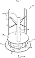
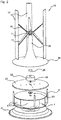
- the gas extractor shown in figures 1 and 2 is intended to be installed at the outlet of a gas evacuation duct on the roof of a building such as a building comprising several dwellings and several floors.
- the fan is placed in contact with a gas flow, called the extraction flow, coming from the gas evacuation duct, flowing in a global direction called the extraction direction and one direction, called the extraction direction 36.
- the gas extractor is designed to be installed on the roof at the outlet of the ventilation ducts, for example at the outlet of a tubular duct in galvanized steel or even a masonry duct.
- the extractor is in particular an extractor whose operation is said to be “low pressure”, that is to say that the pressure generated by the air extractor does not exceed 50 Pa, the pressure generated by the extractor d air being at least 3Pa, and in particular at least 7Pa.
- the pressure generated by the air extractor can for example be between 7 Pa and 50 Pa. However, it can of course also be an extractor making it possible to generate a pressure greater than 50 Pa.
- the extractor comprises a base 31 adapted to be able to be fixed at the outlet of the gas evacuation pipe.
- the base 31 has for example a conical shape of the Venturi type adapted to allow creating a vacuum complementary to the thermal draft at the outlet of the extraction duct.
- the base can for example be formed of concrete so as to ensure good fixing at the outlet of masonry extraction pipes, for example by bonding with a resin.
- the fan 3 is a fan of the centrifugal type with blades 5.
- a fan has the advantage of being suitable for low pressure ventilation by having optimum efficiency with a low speed of rotation of the blades.
- Each blade 5 is fixed to the shaft of the exhaust fan by a fixing edge extending parallel to the axis of the shaft of the exhaust fan.
- the opposite edge, called the free edge, of each blade 5 extends rearward, in the direction of rotation and radially.
- the fan 3 is surmounted by a plate 27 fixed to the base 31 by vertical spacers 6.
- the first coupling device 28 is arranged above the plate 27, the coupling device 28 being connected to the fan shaft 3 through the center of the plate 27.
- the motor 22 is a low consumption motor such as a brushless motor.
- a protective shell 26 of the motor and of the coupling device may be provided between the wind turbine 10 and the plate 27.
- the protective shell 26 has for example a conical shape, the top of which, disposed on the side of the wind turbine 10, is open so as to provide a passage for the shaft 11 of the wind turbine.
- the shaft 11 of the wind turbine is fixed to the top of the protective shell 26 without the protective shell 26 being linked in rotation to the shaft 11 of the wind turbine.
- a ball bearing housed at the top and inside the protective shell 26 can for example be used to hold the shaft 11 of the wind turbine.
- the conical portion of the protective shell 26 is extended around the motor by a portion in the form of a flange 25.
- the protective shell 26 may for example be formed from a metallic material or from a plastic material.
- the motor 22 is fixed to the fan shaft by a sleeve 20, the second coupling device 29 being arranged between the motor and the sleeve
- the wind turbine 10 is a Darrieus type wind turbine with a vertical axis comprising three blades 12, the profile of the blades being of the NACA0018®, EC4040® or even EC6040® type.
- the advantage of such a wind turbine is that it can start on its own for a wide range of wind, especially when the wind speed is between 4m / s and 12m / s.
- the Darrieus type wind turbine can also be completed with a Savonius type wind turbine in its center (variant not shown), thus facilitating the rotation of the Darrieus type wind turbine, in particular with a minimum of wind.
- the first part 14 and the second star-shaped part 15 are fixed to the top of the windmill shaft.
- Each of the blades 12 of the wind turbine 10 extends between one end of a branch of the part 15 in the shape of a star and another end of a branch of the part 14 in star shape arranged below it so that the blades 12 of the wind turbine are arranged vertically.
- Each of the blades 12 of the wind turbine 10 extends vertically towards the flange 25 (without coming into contact with it).
- the wind turbine 10 therefore comprises the blades 12, the parts 14 and 15 in the shape of a three-pointed star and the shaft 11 of the wind turbine.
- the gas extractor also comprises a control unit for the engine and / or the coupling device adapted to generate and transmit to the engine and / or the coupling device at least one control command for the transmission between the shaft 11 of the wind turbine 10 and the fan shaft 3.
- the control unit comprises at least one memory suitable for storing the value of the fan speed setpoint speed.
- the regulation of the fan speed can also be programmed as a function of data from measurements carried out by extraction flow rate sensors, pressure sensors in the extraction duct, or data representative of the indoor air quality such as data measured by relative humidity sensors, CO 2 rate sensors or volatile organic compound (VOC) rate sensors.
- the set speed is for example between 300 rpm and 600 rpm, the set speed is for example 400 rpm.
- the motor can be started in order to assist the starting of the wind turbine, that is to say its rotation if the wind is not sufficient to allow its setting in motion but that it is sufficient to maintain the rotation of the blades of the wind turbine.
- the coupling between the motor and the wind turbine can be achieved using a freewheel or a clutch. This prevents the wind turbine from being driven by the engine if there is no wind, for example. Thus, there is no friction loss of the blades on the air and therefore no negative impact on the power required to be supplied by the engine.
- the coupling between the fan and the motor can be carried out using a free wheel or a clutch. This also makes it possible to limit the friction losses in the case where the friction losses of the freewheel or clutch device are less important than the losses generated by a connection with the engine.
- the extractor represented in figure 1 comprises a motor and is such that the coupling between the motor and the wind turbine is carried out using a first free wheel 28 and the coupling between the fan and the motor is carried out using a second free wheel 29.
- the control unit transmits a signal to start the engine, the direction of rotation of the motor shaft being the direction in which the wind turbine is in freewheel relative to the motor, so that the wind turbine is not rotated when the motor rotates at a speed greater than the speed of rotation of the wind turbine.
- the wind turbine shaft transmits its rotational movement to the fan shaft.
- the freewheel 28 therefore allows the transmission of a mechanical drive torque from the wind turbine to the engine and prevents the transmission of a mechanical drive torque from the engine to the wind turbine.
- the motor provides the additional energy necessary to reach said set speed.
- the motor and the coupling device allow direct transmission between the rotation shaft of the wind turbine and the fan rotation shaft.
- control unit When the wind is strong and the speed of rotation of the wind turbine 10 is higher than the set speed (but less than a speed of rotation, called limit speed, beyond which it would be dangerous to keep the wind turbine coupled to the fan), the control unit is adapted to be able to regulate the speed of rotation of the fan around said set speed, without interrupting the coupling between the wind turbine shaft and the fan shaft.
- control unit of the gas extractor can also provide that when the wind is much too strong, that is to say that it is likely to cause deterioration of one of the components of the '' extractor gas, the transmission between the wind turbine and the fan is interrupted or the wind turbine is stopped for example using a brake.
- the motor can then take over and rotate the fan blades so as to reach the set fan speed.
- the second coupling device 29, interposed between the extraction fan 3 and the motor 22, allows the extraction fan 3 to present a speed of rotation greater than the speed of rotation of the motor 22, in particular in the case where the thermal draft allows this, which improves the efficiency of the device while minimizing the energy consumption supplied by the motor.
- the presence of the second coupling device 29 also makes it possible to take advantage of the inertia of the motor without undergoing the inertia of the wind turbine.
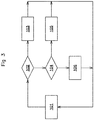
- the figure 3 shows a simplified block diagram of an embodiment of a method of implementing a gas extractor as described above.
- step 101 the tachometer device measures the actual speed of rotation of the exhaust fan and transmits this speed measurement signal to the control unit.
- step 102 the control unit compares the value of the speed measurement signal measured by the tachometer with the set speed, if the speed measured by the tachometer is lower than the set speed, the control unit go to step 103, otherwise the control unit goes to step 104.
- step 103 the control unit develops and supplies a control signal to the motor consisting of an increase in the torque transmitted to the exhaust fan (the torque can be positive or negative, the increase being relative). For example, if a non-zero torque is supplied by the motor to the fan (for example in a situation where there is little wind and where the operation of the extractor is assisted by the motor), then this increase will result in a positive torque, which could for example go from 1Nm to 2Nm. If the wind turbine was already being braked by the engine and the wind has slowed down, the braking must be reduced, we can then for example go from -2Nm to -1Nm. In these two cases, the absolute value of the torque has been increased.
- step 104 the control unit compares the value of the speed measurement signal with the set speed, and, if the value of the speed measurement signal is equal to the set speed, the control unit changes to step 105. If not, the control unit goes to step 106.
- step 105 since it is not necessary to increase the speed of rotation or to brake the exhaust fan, no control signal is transmitted to the motor.
- step 106 the control unit generates and supplies a control signal to the motor consisting of a reduction in the torque transmitted to the exhaust fan (the torque can be positive or negative, the reduction being relative). This amounts, for example, to reducing the value of the torque to be transmitted by the motor from 2Nm to 1Nm, or to increasing the braking from -1Nm to -2Nm.
- Step 101 corresponds to periodic monitoring of the value of the speed measurement signal measured by the tachometer during which the control unit acquires speed measurement signals with a predetermined acquisition frequency. It can also be provided that step 101 is only triggered when the control unit detects that the speed measurement value measured by the tachometer device is different from the set speed.
- the coupling between the fan shaft and the wind turbine can be achieved by a clutch.
- An extractor fitted with such a clutch has the advantage of avoiding friction losses as in a freewheeling device.
- a gas extractor according to the invention can also comprise an external protection device, protecting at least the wind turbine or the whole of the gas extractor against volatiles and so as in particular to prevent an operator from could be injured accidentally by approaching for example a hand of the blades of the wind turbine or the rotating fan. It can for example be a mesh tube (not shown) and does not not disturbing the normal operation of the wind turbine, nor the evacuation of stale gases. By removing or not removing the base of the gas extractor, it can also optionally be provided for the wind turbine and / or the motor and / or the coupling device and / or the exhaust fan to be supported by the device. of external protection and fixed thereto, the external protection device being fixed to the gas evacuation pipe and / or resting fixedly on the roof of the building.
Landscapes
- Engineering & Computer Science (AREA)
- Mechanical Engineering (AREA)
- General Engineering & Computer Science (AREA)
- Chemical & Material Sciences (AREA)
- Combustion & Propulsion (AREA)
- Life Sciences & Earth Sciences (AREA)
- Sustainable Development (AREA)
- Sustainable Energy (AREA)
- Power Engineering (AREA)
- Structures Of Non-Positive Displacement Pumps (AREA)
Description
- L'invention concerne un extracteur de gaz, notamment d'air vicié, comprenant une éolienne, un ventilateur, un moteur et deux dispositifs d'accouplement.
- Un extracteur de gaz est un dispositif comprenant un ventilateur destiné à être installé en sortie d'un conduit d'évacuation d'air de façon à permettre l'extraction des gaz évacués par ce conduit (gaz brûlés d'une chaudière à gaz, à fioul ou encore à bois, fumées produites par une cheminée à bois...) et/ou la ventilation des locaux reliés à ce conduit (notamment les pièces d'habitation telles que les pièces humides : cuisines, salles de bains). L'air vicié évacué permet un renouvellement de l'air situé dans les locaux grâce à des entrées d'air frais extérieur dans les pièces principales ou pièces sèches (par exemple salon, salle à manger, chambres).
- Un extracteur de gaz doit donc présenter une efficacité de ventilation suffisante pour assurer un renouvellement minimum de l'air pour le confort et la sécurité des habitants des locaux. D'autre part, une ventilation excessive des pièces entrainerait une augmentation injustifiée de la consommation énergétique de locaux chauffés liée au chauffage de l'air frais entrant, sans compter la consommation d'énergie supplémentaire liée au fonctionnement du moteur.
- Un extracteur de gaz comprend un ventilateur disposé en sortie d'un conduit d'évacuation d'air, de façon à ce que le ventilateur se trouve dans le flux d'air vicié évacué. Le mouvement de rotation des pales du ventilateur est notamment généré par le tirage thermique. Toutefois, ce phénomène naturel n'est pas nécessairement suffisant pour permettre une extraction suffisante et/ou constante dans le temps.
- Il a donc été proposé des extracteurs de gaz comprenant un ventilateur et un moteur d'entraînement en rotation dudit ventilateur permettant d'augmenter la vitesse de rotation du ventilateur et ainsi le rendement d'extraction de l'air.
- On connait également des extracteurs de gaz comprenant une éolienne permettant d'augmenter le rendement d'extraction du ventilateur en augmentant sa vitesse de rotation sans nécessiter un moteur tel qu'un moteur électrique par exemple. Cependant, le vent étant une source d'énergie naturelle variable, de tels extracteurs ne permettent pas d'assurer une efficacité d'extraction constante, ni d'optimiser la gestion de l'énergie apportée par le vent.
-
DE 20 2004 016620 décrit un extracteur de gaz utilisant l'énergie solaire ou éolienne. Il comprend une éolienne reliée par une roue libre à un arbre d'entraînement ainsi qu'à un moteur et à un ventilateur, le moteur étant disposé entre l'éolienne et le ventilateur. -
CN 102 691 625 décrit un dispositif comprenant une éolienne permettant de générer du courant ou procurer une ventilation, le dispositif comprend également un moteur et un ventilateur. -
CN 105 351 220 décrit un dispositif de conditionnement d'air comprenant un ventilateur, une éolienne à axe vertical ainsi qu'un moteur permettant d'entraîner en rotation le ventilateur. -
US 6 302 778 décrit un extracteur d'air pour toiture comprenant un ventilateur, un moteur et une éolienne. - Il a été proposé par le document
US 1,965,171 un extracteur de gaz comprenant un ventilateur, une éolienne et un moteur adapté pour pouvoir être couplé à l'ensemble formé par le ventilateur et l'éolienne. Lorsque le moteur de l'extracteur de gaz deUS 1,965,171 est à l'arrêt, le moteur n'entrave pas la rotation de l'ensemble formé par le ventilateur et l'éolienne. - Un extracteur de gaz selon
US 1,965,171 permet donc d'augmenter la vitesse de rotation du ventilateur lorsque la vitesse du vent n'est pas suffisante pour assurer une extraction suffisante. - Toutefois, de tels dispositifs ne permettent pas d'optimiser la gestion de l'énergie apportée par le vent, ni de faire face à toutes les situations de vent possibles.
- L'invention vise donc à proposer un extracteur de gaz permettant d'améliorer la fiabilité et la régularité de l'extraction des gaz tout en utilisant au mieux l'énergie provenant d'une éolienne.
- L'invention vise en outre à proposer un extracteur de gaz qui permette de limiter la consommation énergétique liée au fonctionnement de l'extracteur de gaz.
- L'invention vise également à proposer un extracteur de gaz permettant de pallier les situations dans lesquelles le vent est trop fort ou trop faible sans entraîner une augmentation inutile de l'extraction de gaz ni une diminution trop importante de l'extraction de gaz.
- Elle vise également à proposer un tel extracteur de gaz qui soit simple, peu coûteux à réaliser et facile à installer.
- L'invention vise en outre à proposer un tel extracteur de gaz qui soit robuste, résistant aux polluants gras ou chimiques et fiable dans le temps.
- Pour ce faire, l'invention concerne un extracteur de gaz selon la revendication 1.
- Les inventeurs ont constaté que le fait de disposer un premier dispositif d'accouplement entre ladite éolienne et ledit groupe moto-ventilateur d'un extracteur de gaz permet d'optimiser la gestion de l'énergie consommée par le moteur et fournie par l'éolienne en permettant d'interrompre le couplage entre l'éolienne et le groupe moto-ventilateur lorsque cela est souhaitable. La possibilité de pouvoir modifier l'état de couplage/découplage entre l'éolienne et le groupe moto-ventilateur permet d'optimiser la gestion de l'énergie fournie par l'éolienne et utilisée par le moteur en permettant par exemple de désaccoupler l'éolienne du groupe moto-ventilateur lorsqu'il n'y pas de vent ou pas suffisamment de vent pour permettre d'entraîner en rotation le ventilateur d'extraction par l'éolienne, le moteur pouvant alors permettre la rotation du ventilateur d'extraction, ou encore lorsque le vent est trop fort et entraînerait une extraction de gaz trop importante.
- Tout dispositif d'accouplement peut être utilisé. Il peut par exemple s'agir d'un embrayage ou encore d'un dispositif de transmission rotative unidirectionnelle ou « roue libre ».
- Dans une première variante de réalisation d'un extracteur de gaz selon l'invention, ledit premier dispositif d'accouplement est un dispositif de transmission rotative unidirectionnelle. Le dispositif de transmission rotative unidirectionnelle est tel qu'il permet d'éviter au groupe moto-ventilateur d'entraîner l'éolienne en rotation en particulier lorsqu'il n'y a pas de vent et que seul le moteur permet de faire fonctionner le ventilateur (en complément avec le tirage thermique). Ainsi, à l'état de couplage, la roue libre permet à l'éolienne d'entraîner le ventilateur d'extraction (et le moteur) en rotation alors qu'à l'état de découplage, ledit groupe moto-ventilateur n'entraîne pas l'éolienne en rotation, en particulier lorsque la vitesse de rotation du groupe moto-ventilateur est supérieure à la vitesse de rotation de l'éolienne, à la manière d'une roue libre sur une bicyclette. Ceci permet ainsi de limiter la consommation d'énergie par le moteur en supprimant les frottements qui seraient liés à la mise en mouvement de l'éolienne alors qu'il n'y a pas de vent.
- Dans une deuxième variante de réalisation d'un extracteur de gaz selon l'invention, ledit premier dispositif d'accouplement est un embrayage, en particulier un embrayage commandé. Ainsi, à l'état de couplage, l'embrayage permet à l'éolienne d'entraîner le ventilateur d'extraction (et le moteur) en rotation alors qu'à l'état de découplage, c'est-à-dire à l'état débrayé dans ce cas, ledit groupe moto-ventilateur n'entraîne pas l'éolienne en rotation, l'éolienne étant mécaniquement désolidarisée du groupe moto-ventilateur de façon à interrompre la liaison entre l'éolienne et le groupe moto-ventilateur. Similairement à la première variante, ceci permet également de limiter la consommation d'énergie par le moteur en supprimant les frottements qui seraient liés à la mise en mouvement de l'éolienne alors qu'il n'y a pas de vent.
- Comme le premier dispositif d'accouplement, le deuxième dispositif d'accouplement peut également être un dispositif de transmission rotative unidirectionnelle ou bien un embrayage, en particulier un embrayage commandé.
- Selon l'invention, le moteur est interposé entre l'éolienne et le ventilateur d'extraction, le premier dispositif d'accouplement étant toujours interposé entre ladite éolienne et ledit moteur.
- Avantageusement et selon l'invention, un dispositif d'accouplement, appelé deuxième dispositif d'accouplement (le premier dispositif d'accouplement étant le dispositif d'accouplement interposé entre ladite éolienne et ledit groupe moto-ventilateur) est interposé entre le ventilateur d'extraction et le moteur de façon à permettre une vitesse de rotation du ventilateur d'extraction supérieure à celle du moteur, en limitant les pertes par frottement de la liaison entre le ventilateur et le moteur. Un tel dispositif d'accouplement permet donc au dispositif selon l'invention de profiter plus efficacement du tirage thermique éventuel en permettant au ventilateur de présenter une vitesse de rotation supérieure à la vitesse de rotation du moteur. Un tel dispositif d'accouplement, tel qu'un dispositif de transmission rotative unidirectionnelle, peut par exemple permettre au moteur d'entrainer en rotation le ventilateur d'extraction, tout en permettant un entraînement du ventilateur d'extraction par l'éolienne uniquement lorsque la vitesse du vent est suffisante pour atteindre la vitesse de consigne. Ceci permet d'optimiser la gestion par l'unité de commande de l'énergie fournie par l'éolienne et transmise au ventilateur d'extraction, c'est-à-dire d'optimiser l'utilisation du moteur en ne déclenchant son démarrage que si nécessaire.
- Le deuxième dispositif d'accouplement est adapté pour présenter :
- o un premier état, dit état de couplage, dans lequel le moteur est accouplé au ventilateur d'extraction pour pouvoir l'entraîner en rotation (l'éolienne pouvant éventuellement également être accouplée au ventilateur d'extraction),
- o un deuxième état, dit état de découplage, dans lequel ledit moteur n'entraîne pas le ventilateur d'extraction en rotation. La présence du deuxième dispositif d'accouplement permet de pouvoir coupler ou découpler le moteur du ventilateur d'extraction en utilisant par exemple un dispositif de transmission rotative unidirectionnelle juxtaposé au moteur. Selon une variante de réalisation d'un extracteur de gaz selon l'invention, le deuxième dispositif d'accouplement est un dispositif de transmission rotative unidirectionnelle.
- Selon une variante de réalisation exclue de la portée de l'invention, le moteur est disposé sous le ventilateur d'extraction, et n'est alors pas interposé entre le ventilateur d'extraction et l'éolienne. Dans ce cas, l'éolienne est accouplée au ventilateur d'extraction directement au-dessus de ce dernier, seul le premier dispositif d'accouplement étant interposé entre l'éolienne et le ventilateur d'extraction et le deuxième dispositif d'accouplement étant interposé entre le ventilateur d'extraction et le moteur. Dans un tel mode de réalisation, la présence du deuxième dispositif d'accouplement entre le ventilateur d'extraction et le moteur aurait également pour avantage de protéger le moteur de toute détérioration qui pourrait être causée par un entraînement forcé à une vitesse trop importante, par exemple en cas de vent très important (rafales de vent par exemple).
- Avantageusement et selon une variante de réalisation de l'invention, chaque dispositif d'accouplement peut être choisi parmi un dispositif de transmission rotative unidirectionnelle et un embrayage, notamment un embrayage commandé.
- L'extracteur de gaz selon une variante de réalisation de l'invention peut être tel que le couplage entre le ventilateur et le moteur peut être effectué à l'aide d'un dispositif tel qu'une roue libre ou un dispositif d'embrayage.
- Dans une variante de réalisation particulièrement avantageuse d'un extracteur de gaz selon l'invention, le moteur est adapté pour pouvoir freiner la rotation de l'éolienne. Ceci permet également d'optimiser la gestion de l'énergie produite par l'éolienne en permettant de continuer à profiter de l'énergie produite par l'éolienne sans inconvénient en termes d'extraction de gaz (c'est-à-dire en particulier en maintenant une extraction constante). Le moteur est par exemple adapté pour pouvoir fonctionner en génératrice de façon à permettre de ralentir le ventilateur lorsque le vent est trop important et que la vitesse de rotation de l'éolienne tend à être supérieure à la vitesse de consigne, sans interrompre le couplage entre l'éolienne et le ventilateur, c'est-à-dire sans utiliser le moteur uniquement pour entraîner en rotation le ventilateur afin d'atteindre la vitesse de consigne. Le moteur peut également être utilisé pour aider au démarrage de l'éolienne, lorsque le vent est insuffisant pour permettre la mise en mouvement de l'éolienne mais suffisant pour permettre d'entretenir une rotation de l'éolienne.
- Un extracteur de gaz selon une variante de réalisation de l'invention peut comprendre un asservissement permettant de réguler l'extraction du gaz en commandant le moteur et/ou le couplage/découplage du dispositif d'accouplement. Dans une variante de réalisation particulièrement avantageuse d'un extracteur de gaz selon l'invention, l'extracteur de gaz comprend un dispositif de transmission rotative unidirectionnelle entre le moteur et le ventilateur d'extraction. Ainsi, si le tirage thermique est suffisant pour permettre au ventilateur d'extraction de maintenir une vitesse de rotation égale à la vitesse consigne, le ventilateur d'extraction n'entraîne pas le moteur et l'éolienne afin de ne pas entraver la libre rotation des pales du ventilateur d'extraction sous l'effet de la convection naturelle mettant en mouvement le gaz présent dans le conduit d'extraction, ceci peut par exemple être le cas lorsqu'un écart de température suffisamment important existe entre l'intérieur des locaux et l'air extérieur.
- Le moteur peut être un moteur électrique (moteur EC, à balais...) ou autre.
- Dans une variante de réalisation particulièrement avantageuse d'un extracteur de gaz selon l'invention, ledit moteur est adapté pour transmettre un couple au ventilateur d'extraction dont la valeur dépend d'un signal de commande reçu par le moteur,
et l'extracteur de gaz comprend : - un dispositif de mesure délivrant au moins un signal, dit signal de mesure,
- une unité de commande :
- o reliée au dispositif de mesure pour recevoir au moins un signal de mesure, et
- o adaptée pour pouvoir élaborer et fournir un signal de commande au moteur et/ou au premier dispositif d'accouplement (et/ou au deuxième dispositif d'accouplement) en fonction de chaque signal de mesure reçu par l'unité de commande.
- Avantageusement et selon une variante de réalisation de l'invention, l'extracteur de gaz comprend un dispositif tachymétrique délivrant un signal, dit signal de mesure de vitesse, représentatif de la vitesse réelle de rotation du ventilateur d'extraction et en ce que l'unité de commande est :
- ∘ reliée au dispositif tachymétrique pour recevoir ledit signal de mesure de vitesse, et
- ∘ adaptée pour pouvoir élaborer et fournir un signal de commande au moteur et/ou au premier dispositif d'accouplement (et/ou au deuxième dispositif d'accouplement) en fonction dudit signal de mesure de vitesse, de façon à maintenir la vitesse de rotation du ventilateur d'extraction à une vitesse de consigne prédéterminée.
- Un extracteur de gaz selon une variante de réalisation de l'invention peut donc également comprendre un asservissement permettant de réguler l'extraction du gaz en fonction d'un signal de mesure tel que par exemple la vitesse de rotation du ventilateur d'extraction ou encore la pression à l'intérieur d'un conduit d'extraction relié à l'extracteur. Cette variante de réalisation permet d'optimiser la gestion de l'énergie fournie par l'éolienne en permettant d'exploiter au maximum l'énergie qui peut être fournie par l'éolienne, même dans des situations dans lesquelles une autre source d'énergie prend habituellement la place de l'éolienne au lieu de fournir uniquement le couple manquant nécessaire ou de « retirer » (en freinant par exemple) le couple supplémentaire (par exemple lorsque le vent est trop important), et ce, de manière automatisée, sans nécessité de démarrer ou d'arrêter volontairement le moteur, ni de réglage du courant d'alimentation du moteur par un opérateur. Cette variante de réalisation permet donc de réaliser d'importantes économies d'énergie et rend l'extracteur de gaz entièrement ou pratiquement autonome en énergie, sans pour autant diminuer les performances d'extraction de gaz.
- En particulier, dans un extracteur de gaz selon une variante de réalisation de l'invention la vitesse de rotation du ventilateur peut non seulement être augmentée lorsque l'éolienne ne tourne pas à une vitesse suffisante par manque de vent, c'est-à-dire lorsque la vitesse de rotation de l'éolienne tend à être inférieure à la vitesse du ventilateur, mais, le ventilateur peut également être ralenti lorsque l'éolienne présente une vitesse de rotation qui tend à être supérieure à la vitesse de consigne et ce, tout en utilisant le couple fourni par l'éolienne. Avantageusement et selon une variante de réalisation de l'invention, le moteur est adapté pour pouvoir freiner la rotation de l'éolienne.
- Avantageusement et selon une variante de réalisation de l'invention, le dispositif de mesure est adapté pour mesurer un paramètre représentatif d'une grandeur physique du gaz extrait. Le dispositif de mesure peut être adapté pour mesurer tout paramètre représentatif de la qualité de l'extraction de gaz obtenue au cours du fonctionnement de l'extracteur de gaz Le dispositif de mesure peut notamment être un dispositif tachymétrique mesurant la vitesse réelle de rotation du ventilateur d'extraction, il peut également s'agir d'un dispositif de mesure de la pression située dans un conduit d'évacuation de gaz relié à l'extracteur de gaz ou située dans les locaux ou encore d'un dispositif de mesure du débit de gaz dans le conduit d'évacuation de gaz ou encore d'un dispositif de mesure de l'humidité de l'air dans les locaux et/ou dans le conduit d'évacuation de gaz ou encore d'un dispositif de mesure du taux de CO2 ou encore d'un dispositif de mesure du taux de composés organiques volatiles (COV) dans les locaux et/ou dans le conduit d'évacuation de gaz. Un extracteur de gaz selon une variante de réalisation de l'invention peut comprendre un ou plusieurs de ces dispositifs de mesure, au moins l'un d'entre eux transmettant ledit signal de mesure à l'unité de commande qui élabore et fournit un signal de commande au moteur et/ou aux dispositifs d'accouplement en fonction de chaque signal de mesure de façon à maintenir ledit paramètre à une valeur de consigne prédéterminée.
- Dans une variante de réalisation particulièrement avantageuse, l'extracteur de gaz comprend un dispositif tachymétrique délivrant un signal, dit signal de mesure de vitesse, représentatif de la vitesse réelle de rotation du ventilateur d'extraction et en ce que l'unité de commande est :
- ∘ reliée au dispositif tachymétrique pour recevoir ledit signal de mesure de vitesse, et
- ∘ adaptée pour pouvoir élaborer et fournir un signal de commande au moteur et/ou au premier dispositif d'accouplement (et/ou au deuxième dispositif d'accouplement)en fonction dudit signal de mesure de vitesse, de façon à maintenir la vitesse de rotation du ventilateur d'extraction à une vitesse de consigne prédéterminée.
- Dans une variante particulièrement avantageuse, un extracteur de gaz comprend :
- un ventilateur d'extraction,
- une éolienne accouplée au ventilateur d'extraction pour pouvoir l'entraîner en rotation,
- un moteur interposé entre le ventilateur d'extraction et l'éolienne, ledit moteur étant accouplé au ventilateur d'extraction pour pouvoir l'entraîner en rotation et adapté pour transmettre un couple au ventilateur d'extraction dont la valeur dépend d'un signal de commande reçu par le moteur,
- un dispositif tachymétrique délivrant un signal, dit signal de mesure de vitesse, représentatif de la vitesse réelle de rotation du ventilateur d'extraction,
- une unité de commande :
- ∘ reliée au dispositif tachymétrique pour recevoir ledit signal de mesure de vitesse, et
- ∘ adaptée pour pouvoir élaborer et fournir un signal de commande au moteur en fonction dudit signal de mesure de vitesse, de façon à maintenir la vitesse de rotation du ventilateur d'extraction à une vitesse de consigne prédéterminée.
- L'éolienne, chaque dispositif d'accouplement et le groupe moto-ventilateur peuvent être liés entre eux par un ou plusieurs arbres rotatifs. Avantageusement et selon une variante de réalisation de l'invention, l'éolienne est reliée au premier dispositif d'accouplement par un arbre, dit arbre éolien, rotatif sur lequel sont fixées des pales, dites pales d'éolienne. Avantageusement et selon une variante de réalisation de l'invention, le ventilateur d'extraction est relié au deuxième dispositif d'accouplement par un arbre, dit arbre du ventilateur, rotatif. Tout autre dispositif de transmission peut également être utilisé.
- Le ventilateur d'extraction peut être de type axial ou encore de type centrifuge ou hélicocentrifuge. La géométrie et le nombre de pales du ventilateur d'extraction peut varier. Avantageusement et selon une variante de réalisation de l'invention, le ventilateur d'extraction est un ventilateur de type centrifuge. Le ventilateur d'extraction est adapté pour permettre d'extraire de façon optimale un flux d'air vicié provenant d'au moins un conduit d'évacuation de gaz du bâtiment. Le ventilateur d'extraction peut par exemple être un ventilateur de type centrifuge à pales courbées vers l'arrière, c'est-à-dire que le bord libre de chaque pale s'étend vers l'arrière, dans le sens de rotation, et radialement.
- Selon l'invention, l'éolienne est une éolienne à axe vertical ou une éolienne à axe horizontal et l'arbre de l'éolienne est parallèle à l'arbre du ventilateur. Dans une variante particulièrement avantageuse d'un extracteur selon l'invention, ladite éolienne est une éolienne de type Darrieus. Dans une variante particulièrement avantageuse d'un extracteur selon l'invention, ladite éolienne comprend trois pales.
- Le ventilateur est disposé au plus proche de la sortie du flux d'extraction de gaz provenant des locaux du bâtiment sur lequel l'extracteur de gaz est installé. Le ventilateur est disposé au contact d'un flux gazeux, dit flux d'extraction, provenant dudit conduit d'évacuation de gaz, circulant dans une direction globale dite direction d'extraction et un sens, dit sens d'extraction. Le dispositif d'accouplement et l'éolienne sont donc installés à côté ou, de préférence, au-dessus du ventilateur, c'est-à-dire en aval du sens d'extraction de l'extracteur, le flux d'extraction du gaz étant dirigé vers le haut (à l'intérieur du conduit d'extraction). Avantageusement, ladite éolienne est disposée en aval du ventilateur dans le sens d'extraction. Selon l'invention, l'éolienne est une éolienne à axe vertical, l'arbre du ventilateur et l'arbre de l'éolienne sont parallèles l'un à l'autre et disposés selon une même direction.
- Un extracteur de gaz selon l'invention est prévu pour être installé sur la toiture d'un bâtiment, en sortie d'au moins un conduit d'évacuation de gaz. Un extracteur de gaz selon l'invention peut être disposé en sortie de tout type de conduit tel qu'un conduit circulaire en acier galvanisé ou encore un conduit maçonné. Un extracteur de gaz selon une variante de réalisation de l'invention peut également comprendre un dispositif de fixation permettant de solidariser l'extracteur par rapport à au moins un conduit d'évacuation de gaz auquel il est relié. Dans une variante de réalisation particulièrement avantageuse d'un extracteur de gaz selon l'invention, ledit extracteur de gaz comprend une embase adaptée pour pouvoir être fixée en sortie dudit conduit d'évacuation de gaz. En particulier, avantageusement et selon une variante de réalisation de l'invention, l'embase est disposée sous ledit groupe moto-ventilateur.
- D'autres buts, caractéristiques et avantages de l'invention apparaîtront au vu de la description qui va suivre et des dessins annexés dans lesquels :
- la
figure 1 représente une vue en perspective d'un extracteur de gaz selon l'invention, - la
figure 2 représente une vue en perspective éclatée d'un extracteur de gaz selon l'invention, - la
figure 3 représente un schéma synoptique d'un procédé de mise en œuvre d'un extracteur de gaz selon l'invention. - L'extracteur de gaz représenté aux
figures 1 et2 est destiné à être installé en sortie d'un conduit d'évacuation de gaz sur la toiture d'un bâtiment tel qu'un immeuble comprenant plusieurs logements et plusieurs étages. - L'extracteur de gaz comprend :
- un ventilateur d'extraction 3 comprenant un arbre, dit arbre du ventilateur (non visible sur les
figures 1 et2 ), entraînant en rotation des aubes 5 à une vitesse de consigne prédéterminée, - une éolienne 10 comprenant un arbre 11, dit arbre de l'éolienne, entraîné en rotation par trois pales 12 à une vitesse, dite vitesse de rotation de l'éolienne,
- un moteur 22 entre l'arbre du ventilateur et l'arbre 11 de l'éolienne,
- un premier dispositif d'accouplement 28 interposé entre l'éolienne 10 et ledit groupe moto-ventilateur,
- et un deuxième dispositif d'accouplement 29, interposé entre le ventilateur 3 d'extraction et le moteur 22.
- Le ventilateur est disposé au contact d'un flux gazeux, dit flux d'extraction, provenant du conduit d'évacuation de gaz, circulant dans une direction globale dite direction d'extraction et un sens, dit sens d'extraction 36.
- L'extracteur de gaz est prévu pour être installé en toiture en sortie des conduits de ventilation, par exemple en sortie d'un conduit tubulaire en acier galvanisé ou encore d'un conduit maçonné.
- L'extracteur est en particulier un extracteur dont le fonctionnement est dit « basse pression », c'est-à-dire que la pression générée par l'extracteur d'air n'excède pas 50Pa, la pression générée par l'extracteur d'air étant d'au moins 3Pa, et notamment d'au moins 7Pa. La pression générée par l'extracteur d'air peut par exemple être comprise entre 7Pa et 50Pa. Toutefois, il peut bien sûr également s'agir d'un extracteur permettant de générer une pression supérieure à 50Pa.
- L'extracteur comprend une embase 31 adaptée pour pouvoir être fixée en sortie du conduit d'évacuation de gaz. Dans l'extracteur de gaz représenté aux
figures 1 et2 , l'embase 31 présente par exemple une forme conique de type Venturi adaptée pour permettre de créer une dépression complémentaire au tirage thermique en sortie du conduit d'extraction. L'embase peut par exemple être formée en béton de façon à assurer une bonne fixation en sortie de conduits d'extraction maçonnés, par exemple par collage avec une résine. - Dans le mode de réalisation préférentiel représenté en
figure 1 , le ventilateur 3 est un ventilateur de type centrifuge à pales 5. Un tel ventilateur a pour avantage d'être adapté à une ventilation basse pression en présentant une efficacité optimale avec une faible vitesse de rotation des pales. Chaque pale 5 est fixée à l'arbre du ventilateur d'extraction par un bord de fixation s'étendant parallèlement à l'axe de l'arbre du ventilateur d'extraction. Le bord opposé, dit bord libre, de chaque pale 5 s'étend vers l'arrière, dans le sens de rotation et radialement. - Le ventilateur 3 est surmonté d'un plateau 27 fixé à l'embase 31 par des entretoises verticales 6.
- Le premier dispositif d'accouplement 28 est disposé au-dessus du plateau 27, le dispositif d'accouplement 28 étant lié à l'arbre du ventilateur 3 à travers le centre du plateau 27.
- Le moteur 22 est un moteur à basse consommation tel qu'un moteur sans balais. Une coque de protection 26 du moteur et du dispositif d'accouplement peut être prévue entre l'éolienne 10 et le plateau 27. La coque de protection 26 présente par exemple une forme conique dont le sommet, disposé du côté de l'éolienne 10, est ouvert de façon à ménager un passage pour l'arbre 11 de l'éolienne. L'arbre 11 de l'éolienne est fixé au sommet de la coque de protection 26 sans que la coque de protection 26 ne soit liée en rotation à l'arbre 11 de l'éolienne. Un roulement à billes logé au sommet et à l'intérieur de la coque de protection 26 peut par exemple être utilisé pour maintenir l'arbre 11 de l'éolienne. La portion conique de la coque de protection 26 se prolonge autour du moteur par une portion sous la forme d'une flasque 25. La coque de protection 26 peut par exemple être formée d'un matériau métallique ou d'un matériau plastique. Le moteur 22 est fixé à l'arbre du ventilateur par une douille 20, le deuxième dispositif d'accouplement 29 étant disposé entre le moteur et la douille 20.
- Dans le mode de réalisation préférentiel représenté en
figure 1 , l'éolienne 10 est une éolienne de type Darrieus à axe vertical comprenant trois pales 12, le profil des pales étant de type NACA0018®, EC4040® ou encore EC6040®. Une telle éolienne a pour avantage de pouvoir démarrer seule pour une large plage de vent, notamment lorsque la vitesse de vent est comprise entre 4m/s et 12m/s. L'éolienne de type Darrieus peut également être complétée d'une éolienne de type Savonius en son centre (variante non représentée), facilitant ainsi la mise en rotation de l'éolienne de type Darrieus, en particulier avec un minimum de vent. - Deux pièces 14 et 15 en forme d'étoile à trois branches, avec un angle de 120° entre chaque branche, supportent les pales 12 de l'éolienne et sont fixées en leur centre à l'arbre 11 de l'éolienne 10. La première pièce 14 et la deuxième pièce 15 en forme d'étoile sont fixées au sommet de l'arbre de l'éolienne. Chacune des pales 12 de l'éolienne 10 s'étend entre une extrémité d'une branche de la pièce 15 en forme d'étoile et une autre extrémité d'une branche de la pièce 14 en forme d'étoile disposée en-dessous de celle-ci de façon à ce que les pales 12 de l'éolienne soient disposées verticalement. Chacune des pales 12 de l'éolienne 10 se prolonge verticalement vers la flasque 25 (sans entrer en contact avec celle-ci). L'éolienne 10 comprend donc les pales 12, les pièces 14 et 15 en forme d'étoile à trois branches et l'arbre 11 de l'éolienne.
- L'extracteur de gaz comprend également une unité de commande du moteur et/ou du dispositif d'accouplement adaptée pour générer et transmettre au moteur et/ou au dispositif d'accouplement au moins une commande de régulation de la transmission entre l'arbre 11 de l'éolienne 10 et l'arbre du ventilateur 3. L'unité de commande comprend au moins une mémoire adaptée pour mémoriser la valeur de la vitesse de consigne de rotation du ventilateur. La régulation de la vitesse de rotation du ventilateur peut également être programmée en fonction de données issues de mesures effectuées par des capteurs de débit du flux d'extraction, des capteurs de pression dans le conduit d'extraction, ou encore de données représentatives de la qualité de l'air intérieur telles que des données mesurées par des capteurs d'humidité relative, des capteurs de taux de CO2 ou encore des capteurs de taux de composés organiques volatiles (COV).
- La vitesse de consigne est par exemple comprise entre 300tr/min et 600tr/min, la vitesse de consigne est par exemple de 400 tr/min.
- Si nécessaire, le moteur peut être mis en marche afin d'assister le démarrage de l'éolienne, c'est-à-dire sa mise en rotation si le vent n'est pas suffisant pour permettre sa mise en mouvement mais qu'il est suffisant pour entretenir la rotation des pales de l'éolienne.
- Le couplage entre le moteur et l'éolienne peut être réalisé à l'aide d'une roue libre ou d'un d'embrayage. Cela permet d'éviter que l'éolienne soit entraînée par le moteur s'il n'y a pas de vent par exemple. Ainsi, il n'y a pas de pertes par frottement des pales sur l'air et donc pas d'impact négatif sur la puissance nécessaire devant être fournie par le moteur.
- D'autre part, le couplage entre le ventilateur et le moteur peut être effectué à l'aide d'une roue libre ou d'un d'embrayage. Cela permet également de limiter les pertes par frottement dans le cas où les pertes par frottement du dispositif de roue libre ou d'embrayage sont moins importantes que les pertes générées par une liaison avec le moteur.
- L'extracteur représenté en
figure 1 comprend un moteur et est tel que le couplage entre le moteur et l'éolienne est réalisé à l'aide d'une première roue libre 28 et le couplage entre le ventilateur et le moteur est réalisé à l'aide d'une deuxième roue libre 29. Ainsi, s'il n'y a pas assez de vent, l'unité de commande transmet un signal de mise en marche du moteur, le sens de rotation de l'arbre moteur étant le sens dans lequel l'éolienne est en roue libre par rapport au moteur, de façon à ce que l'éolienne ne soit pas entraînée en rotation lorsque le moteur tourne à une vitesse supérieure à la vitesse de rotation de l'éolienne. À l'inverse, lorsque le moteur est à l'arrêt, par exemple parce qu'il y a suffisamment de vent, l'arbre de l'éolienne transmet son mouvement de rotation à l'arbre du ventilateur. Dans ce cas, la roue libre 28 permet donc la transmission d'un couple d'entrainement mécanique de l'éolienne vers le moteur et empêche la transmission d'un couple d'entrainement mécanique du moteur vers l'éolienne. D'autre part, lorsque le vent n'est pas suffisant pour permettre d'atteindre la vitesse consigne uniquement grâce à l'éolienne, le moteur fournit le complément d'énergie nécessaire pour atteindre ladite vitesse de consigne. - Lorsque le vent est tel qu'il permet que la vitesse de rotation de l'éolienne soit égale à la vitesse de consigne, le moteur et le dispositif d'accouplement permettent une transmission directe entre l'arbre de rotation de l'éolienne et l'arbre de rotation du ventilateur.
- Lorsque le vent est important et que la vitesse de rotation de l'éolienne 10 est supérieure à la vitesse de consigne (mais inférieure à une vitesse de rotation, dite vitesse limite, au-delà de laquelle il serait dangereux de maintenir l'éolienne couplée au ventilateur), l'unité de commande est adaptée pour pouvoir réguler la vitesse de rotation du ventilateur autour de ladite vitesse de consigne, sans interruption du couplage entre l'arbre de l'éolienne et l'arbre du ventilateur.
- Bien sûr, l'unité de commande de l'extracteur de gaz peut également prévoir que lorsque le vent est beaucoup trop important, c'est-à-dire qu'il est susceptible d'entraîner une détérioration d'un des composants de l'extracteur de gaz, la transmission entre l'éolienne et le ventilateur est interrompue ou l'éolienne est arrêtée par exemple à l'aide d'un frein. Dans ce cas particulier et exceptionnel, le moteur peut alors prendre le relais et entraîner en rotation les pales du ventilateur de façon à atteindre la vitesse de rotation consigne du ventilateur.
- Le deuxième dispositif d'accouplement 29, interposé entre le ventilateur 3 d'extraction et le moteur 22, permet au ventilateur 3 d'extraction de présenter une vitesse de rotation supérieure à la vitesse de rotation du moteur 22, notamment dans le cas où le tirage thermique le permet, ce qui améliore l'efficacité du dispositif tout en minimisant la consommation d'énergie fournie par le moteur. La présence du deuxième dispositif d'accouplement 29 permet également de profiter de l'inertie du moteur sans subir l'inertie de l'éolienne.
- La
figure 3 représente un schéma synoptique simplifié d'un mode de réalisation d'un procédé de mise en œuvre d'un extracteur de gaz tel que décrit ci-dessus. - À l'étape 101, le dispositif tachymétrique mesure la vitesse réelle de rotation du ventilateur d'extraction et transmet ce signal de mesure de vitesse à l'unité de commande. À l'étape 102, l'unité de commande compare la valeur du signal de mesure de vitesse mesuré par le dispositif tachymétrique à la vitesse consigne, si la vitesse mesurée par le dispositif tachymétrique est inférieure à la vitesse consigne, l'unité de commande passe à l'étape 103, sinon l'unité de commande passe à l'étape 104.
- À l'étape 103, l'unité de commande élabore et fournit un signal de commande au moteur consistant en une augmentation du couple transmis au ventilateur d'extraction (le couple pouvant être positif ou négatif, l'augmentation étant relative). Par exemple, si un couple non nul est fourni par le moteur au ventilateur (par exemple dans une situation où il y a peu de vent et où le fonctionnement de l'extracteur est assisté par le moteur), alors cette augmentation se traduira par un couple positif, qui pourra par exemple passer de 1Nm à 2Nm. Si l'éolienne était déjà en train d'être freinée par le moteur et que le vent a ralenti, il faut diminuer le freinage, on peut alors par exemple passer de -2Nm à -1Nm. Dans ces deux cas, la valeur absolue du couple a été augmentée.
- À l'étape 104, l'unité de commande compare la valeur du signal de mesure de vitesse à la vitesse consigne, et, si la valeur du signal de mesure de vitesse est égale à la vitesse consigne, l'unité de commande passe à l'étape 105. Dans la négative, l'unité de commande passe à l'étape 106.
- À l'étape 105, comme il n'est pas nécessaire d'augmenter la vitesse de rotation ou de freiner le ventilateur d'extraction, aucun signal de commande n'est transmis au moteur.
- À l'étape 106, l'unité de commande élabore et fournit un signal de commande au moteur consistant en une diminution du couple transmis au ventilateur d'extraction (le couple pouvant être positif ou négatif, la diminution étant relative). Cela revient par exemple à diminuer la valeur du couple à transmettre par le moteur de 2Nm à 1Nm, ou à augmenter le freinage de -1Nm à -2Nm.
- L'étape 101 correspond à une surveillance périodique de la valeur du signal de mesure de vitesse mesurée par le dispositif tachymétrique au cours de laquelle l'unité de commande acquiert des signaux de mesure de vitesse avec une fréquence d'acquisition prédéterminée. Il peut également être prévu que l'étape 101 n'est déclenchée que lorsque l'unité de commande détecte que la valeur de mesure de vitesse mesurée par le dispositif tachymétrique est différente de la vitesse consigne.
- Dans une autre variante de réalisation particulièrement avantageuse d'un extracteur selon l'invention, le couplage entre l'arbre du ventilateur et l'éolienne peut être réalisé par un embrayage. Un extracteur muni d'un tel embrayage présente l'avantage d'éviter des pertes par frottement comme dans un dispositif à roue libre.
- En outre, un extracteur de gaz selon l'invention peut également comprendre un dispositif de protection extérieur, protégeant au moins l'éolienne ou l'ensemble de l'extracteur de gaz contre les volatiles et de façon à empêcher notamment qu'un opérateur ne puisse se blesser accidentellement en approchant par exemple une main des pales de l'éolienne ou du ventilateur en rotation. Il peut par exemple s'agir d'un tube grillagé (non représenté) et ne perturbant pas le fonctionnement normal de l'éolienne, ni l'évacuation des gaz viciés. En supprimant ou non l'embase de l'extracteur de gaz, il peut également éventuellement être prévu que l'éolienne et/ou le moteur et/ou le dispositif d'accouplement et/ou le ventilateur d'extraction soient supportés par le dispositif de protection extérieur et fixés à celui-ci, le dispositif de protection extérieur étant fixé à la conduite d'évacuation de gaz et/ou reposant fixement sur la toiture du bâtiment.
- Bien entendu, cette description est donnée à titre d'exemple illustratif uniquement et l'homme du métier pourra y apporter de nombreuses modifications sans sortir de la portée de l'invention, comme par exemple prévoir un deuxième moteur permettant d'enclencher la mise en mouvement de l'éolienne. Par ailleurs, l'éolienne de type Darrieus peut par exemple être complétée d'une éolienne de type Savonius en son centre, facilitant ainsi la mise en rotation de l'éolienne de type Darrieus. La portée de l'invention est uniquement définie par les revendications jointes en annexe.
Claims (12)
- Extracteur (1) de gaz comprenant :- un groupe, dit groupe moto-ventilateur, comprenant :∘ un ventilateur (3) d'extraction comprenant un arbre rotatif, dit arbre du ventilateur, et un nombre de pales (5),∘ un moteur (22) accouplé au ventilateur d'extraction pour pouvoir l'entraîner en rotation,- une éolienne (10) accouplée au groupe moto-ventilateur pour pouvoir l'entraîner en rotation, l'éolienne (10) comprenant un arbre rotatif, dit arbre de l'éolienne (11),dans lequel:- l'arbre du ventilateur et l'arbre de l'éolienne (11) sont parallèles l'un à l'autre et disposés selon une même direction, l'éolienne (11) étant une éolienne à axe vertical,- un premier dispositif d'accouplement (28), interposé entre ladite éolienne (10) et ledit moteur (22), ledit moteur (22) étant disposé entre le ventilateur (3) d'extraction et l'éolienne (10),- ledit premier dispositif d'accouplement étant adapté pour présenter :caractérisé en ce que :∘ un premier état, dit état de couplage, dans lequel l'éolienne (10) est accouplée au groupe moto-ventilateur pour pouvoir l'entraîner en rotation,∘ un deuxième état, dit état de découplage, dans lequel ledit groupe moto-ventilateur n'entraîne pas l'éolienne (10) en rotation,- l'extracteur de gaz comprend en outre un deuxième dispositif d'accouplement (29), interposé entre le ventilateur (3) d'extraction et le moteur (22), de façon à permettre une vitesse de rotation du ventilateur (3) d'extraction supérieure à celle du moteur (22), le moteur et l'éolienne n'entravant alors pas la libre rotation des pales du ventilateur d'extraction.
- Extracteur de gaz selon la revendication 1, caractérisé en ce que ledit premier dispositif d'accouplement est un dispositif de transmission rotative unidirectionnelle.
- Extracteur de gaz selon la revendication 1, caractérisé en ce que ledit premier dispositif d'accouplement est un embrayage, en particulier un embrayage commandé.
- Extracteur de gaz selon l'une des revendications 1 à 3, caractérisé en ce que le moteur est adapté pour pouvoir freiner la rotation de l'éolienne.
- Extracteur de gaz selon l'une des revendications 1 à 4, caractérisé en ce que :- ledit moteur (22) est adapté pour transmettre un couple au ventilateur (3) d'extraction dont la valeur dépend d'un signal de commande reçu par le moteur,et en ce que l'extracteur de gaz comprend :- un dispositif de mesure délivrant au moins un signal, dit signal de mesure,- une unité de commande :∘ reliée au dispositif de mesure pour recevoir au moins un signal de mesure, et∘ adaptée pour pouvoir élaborer et fournir un signal de commande au moteur et/ou au premier dispositif d'accouplement en fonction de chaque signal de mesure reçu par l'unité de commande.
- Extracteur de gaz selon la revendication 5, caractérisé en ce qu'il comprend un dispositif tachymétrique délivrant un signal, dit signal de mesure de vitesse, représentatif de la vitesse réelle de rotation du ventilateur (3) d'extraction et en ce que l'unité de commande est :∘ reliée au dispositif tachymétrique pour recevoir ledit signal de mesure de vitesse, et∘ adaptée pour pouvoir élaborer et fournir un signal de commande au moteur et/ou au premier dispositif d'accouplement en fonction dudit signal de mesure de vitesse, de façon à maintenir la vitesse de rotation du ventilateur d'extraction à une vitesse de consigne prédéterminée.
- Extracteur de gaz selon l'une des revendications 1 à 6, caractérisé en ce que l'éolienne (10) est reliée au premier dispositif d'accouplement par ledit arbre éolien sur lequel sont fixées des pales, dites pales d'éolienne.
- Extracteur de gaz selon l'une des revendications 1 à 7, caractérisé en ce que le ventilateur (3) d'extraction est relié au deuxième dispositif d'accouplement par ledit arbre du ventilateur.
- Extracteur de gaz selon l'une des revendications 1 à 8, caractérisé en ce que ladite éolienne est une éolienne de type Darrieus.
- Extracteur de gaz selon l'une des revendications 1 à 9, caractérisé en ce qu'il comprend une embase (31) adaptée pour pouvoir être fixée en sortie d'un conduit d'évacuation de gaz.
- Extracteur de gaz selon l'une des revendications 1 à 10, caractérisé en ce que le deuxième dispositif d'accouplement est adapté pour présenter :∘ un premier état, dit état de couplage, dans lequel le moteur est accouplé au ventilateur d'extraction pour pouvoir l'entraîner en rotation,∘ un deuxième état, dit état de découplage, dans lequel ledit moteur n'entraîne pas le ventilateur d'extraction en rotation.
- Extracteur de gaz selon l'une des revendications 1 à 11, caractérisé en ce que le deuxième dispositif d'accouplement est un dispositif de transmission rotative unidirectionnelle.
Applications Claiming Priority (1)
| Application Number | Priority Date | Filing Date | Title |
|---|---|---|---|
| FR1654421A FR3051517B1 (fr) | 2016-05-18 | 2016-05-18 | Extracteur de gaz comprenant une eolienne, un ventilateur, un moteur et un dispositif d'accouplement |
Publications (2)
| Publication Number | Publication Date |
|---|---|
| EP3246576A1 EP3246576A1 (fr) | 2017-11-22 |
| EP3246576B1 true EP3246576B1 (fr) | 2020-03-18 |
Family
ID=56557770
Family Applications (1)
| Application Number | Title | Priority Date | Filing Date |
|---|---|---|---|
| EP17171610.3A Active EP3246576B1 (fr) | 2016-05-18 | 2017-05-17 | Extracteur de gaz comprenant une éolienne, un ventilateur, un moteur et un dispositif d'accouplement |
Country Status (3)
| Country | Link |
|---|---|
| EP (1) | EP3246576B1 (fr) |
| ES (1) | ES2797115T3 (fr) |
| FR (1) | FR3051517B1 (fr) |
Families Citing this family (2)
| Publication number | Priority date | Publication date | Assignee | Title |
|---|---|---|---|---|
| CN110975429A (zh) * | 2019-12-02 | 2020-04-10 | 安徽同益净化科技有限公司 | 一种可快速改变滤纸型号的空气净化器 |
| CN111502932B (zh) * | 2020-04-27 | 2021-02-26 | 温州承玥机械设备有限公司 | 一种节能式方便拆卸检修的风能发电机用散热结构 |
Family Cites Families (8)
| Publication number | Priority date | Publication date | Assignee | Title |
|---|---|---|---|---|
| US1965171A (en) | 1933-02-06 | 1934-07-03 | Harold R Boyer | Ventilator |
| JPS5690482U (fr) * | 1979-12-17 | 1981-07-18 | ||
| US4416415A (en) * | 1981-10-20 | 1983-11-22 | Leonard W. Suroff | Automatic damper assembly |
| US6302778B1 (en) * | 1999-05-13 | 2001-10-16 | Gabriel Andrews | Turbine roof ventilator |
| AU2002301161B2 (en) * | 2000-10-12 | 2008-01-17 | Andrews, Gabriel | Turbine ventilator |
| DE202004016620U1 (de) * | 2004-10-27 | 2005-03-31 | Duehring Karl Heinz | Abluft- und Zuluftventilatoren, die über eine Antriebswelle mittels Windenergie und/oder Solarstrom und/oder Netzstrom energieeinsparend betrieben werden, und deren Fortluft- oder Aussenluftdurchlässe nach Lee ausgerichtet werden |
| CN102691625A (zh) * | 2011-03-25 | 2012-09-26 | 孙善骏 | 风力发电自驱风机 |
| CN105351220B (zh) * | 2015-10-30 | 2018-04-06 | 东莞理工学院 | 垂直轴风力转动机与电机结合驱动的冷却塔及控制方法 |
-
2016
- 2016-05-18 FR FR1654421A patent/FR3051517B1/fr active Active
-
2017
- 2017-05-17 EP EP17171610.3A patent/EP3246576B1/fr active Active
- 2017-05-17 ES ES17171610T patent/ES2797115T3/es active Active
Non-Patent Citations (1)
| Title |
|---|
| None * |
Also Published As
| Publication number | Publication date |
|---|---|
| EP3246576A1 (fr) | 2017-11-22 |
| FR3051517B1 (fr) | 2021-06-04 |
| ES2797115T3 (es) | 2020-12-01 |
| FR3051517A1 (fr) | 2017-11-24 |
Similar Documents
| Publication | Publication Date | Title |
|---|---|---|
| EP0204611B1 (fr) | Dispositif d'aération des locaux et de tirage des cheminées | |
| EP1999412B1 (fr) | Procede et systeme de chauffage / rafraichissement et ventilation d'un local | |
| EP1961956A1 (fr) | Eolienne d'axe vertical | |
| JP4682230B2 (ja) | 風力発電用ブースター風車風洞体 | |
| FR2597166A1 (fr) | Ventilateur centrifuge, et dispositif et procede pour faire varier le pas de ses pales | |
| JP2010001881A5 (fr) | ||
| EP3246576A1 (fr) | Extracteur de gaz comprenant une éolienne, un ventilateur, un moteur et un dispositif d'accouplement | |
| EP2360433B1 (fr) | Dispositif d'assistance mécanique pour l'évacuation de flux gazeux plus particulièrement destiné à un ensemble habitable et procédé d'extraction de l'air vicié | |
| FR2957661A1 (fr) | Installation de ventilation d'un local et procede de regulation d'une telle installation | |
| FR3012583A1 (fr) | Dispositif de controle d'une centrale de traitement d'air | |
| FR2969255A1 (fr) | Procede de parametrage d'une installation de ventilation et installation de ventilation adaptee a mettre en oeuvre ce procede | |
| EP2442041B1 (fr) | Installation de ventilation mécanique par insufflation hygrorégulée et procédé associé | |
| FR2954416A1 (fr) | Eolienne implantee au dernier etage d'une habitation, en particulier en zone urbaine | |
| FR2587458A2 (fr) | Dispositif d'aeration des locaux et de tirage des cheminees | |
| EP2282136B1 (fr) | Installation de ventilation mécanique contrôlée à double flux d'un bâtiment | |
| EP3412976B1 (fr) | Système de chauffage, pour le chauffage des pièces d'une habitation, comprenant un appareil de chauffage principal et une installation de distribution d'air | |
| FR3017191A3 (fr) | Dispositif de reception de chaleur | |
| WO2022195203A1 (fr) | Turbine pour bouche d'aeration et bouche d'aeration autonome en energie compatible avec une large gamme de debits d'air | |
| EP3343121B1 (fr) | Bouche d'extraction ou d'insufflation d'air | |
| EP3118529B1 (fr) | Système de chauffage et de production d'eau chaude dans une habitation | |
| FR2982011A1 (fr) | Dispositif de recuperation de chaleur pour un poele, notamment un poele a bois, ainsi qu'installation correspondante de chauffage d'un batiment | |
| FR2926129A1 (fr) | Dispositif et procede de regulation d'un ventilateur et extracteur hybride d'air vicie equipe d'un tel dispositif | |
| FR2986607A1 (fr) | Procede de regulation d'un groupe de commande d'un ventilateur, et groupe correspondant | |
| FR2491589A1 (fr) | Dispositif de regulation de temperature pour chauffe-eau chauffes au gaz et au fuel | |
| EP2558793B1 (fr) | Dispositif de modulation de l'entree de l'air |
Legal Events
| Date | Code | Title | Description |
|---|---|---|---|
| PUAI | Public reference made under article 153(3) epc to a published international application that has entered the european phase |
Free format text: ORIGINAL CODE: 0009012 |
|
| STAA | Information on the status of an ep patent application or granted ep patent |
Free format text: STATUS: THE APPLICATION HAS BEEN PUBLISHED |
|
| AK | Designated contracting states |
Kind code of ref document: A1 Designated state(s): AL AT BE BG CH CY CZ DE DK EE ES FI FR GB GR HR HU IE IS IT LI LT LU LV MC MK MT NL NO PL PT RO RS SE SI SK SM TR |
|
| AX | Request for extension of the european patent |
Extension state: BA ME |
|
| STAA | Information on the status of an ep patent application or granted ep patent |
Free format text: STATUS: REQUEST FOR EXAMINATION WAS MADE |
|
| 17P | Request for examination filed |
Effective date: 20180517 |
|
| RBV | Designated contracting states (corrected) |
Designated state(s): AL AT BE BG CH CY CZ DE DK EE ES FI FR GB GR HR HU IE IS IT LI LT LU LV MC MK MT NL NO PL PT RO RS SE SI SK SM TR |
|
| STAA | Information on the status of an ep patent application or granted ep patent |
Free format text: STATUS: EXAMINATION IS IN PROGRESS |
|
| 17Q | First examination report despatched |
Effective date: 20190614 |
|
| REG | Reference to a national code |
Ref country code: DE Ref legal event code: R079 Ref document number: 602017013118 Country of ref document: DE Free format text: PREVIOUS MAIN CLASS: F04D0025000000 Ipc: F04D0027000000 |
|
| GRAP | Despatch of communication of intention to grant a patent |
Free format text: ORIGINAL CODE: EPIDOSNIGR1 |
|
| STAA | Information on the status of an ep patent application or granted ep patent |
Free format text: STATUS: GRANT OF PATENT IS INTENDED |
|
| RIC1 | Information provided on ipc code assigned before grant |
Ipc: F23L 17/00 20060101ALI20191127BHEP Ipc: F04D 27/00 20060101AFI20191127BHEP Ipc: F24F 3/16 20060101ALI20191127BHEP Ipc: F04D 25/04 20060101ALI20191127BHEP Ipc: F04D 25/02 20060101ALI20191127BHEP Ipc: F03D 3/06 20060101ALI20191127BHEP Ipc: F04D 25/06 20060101ALI20191127BHEP Ipc: F03D 9/28 20160101ALI20191127BHEP |
|
| INTG | Intention to grant announced |
Effective date: 20191212 |
|
| GRAS | Grant fee paid |
Free format text: ORIGINAL CODE: EPIDOSNIGR3 |
|
| GRAA | (expected) grant |
Free format text: ORIGINAL CODE: 0009210 |
|
| STAA | Information on the status of an ep patent application or granted ep patent |
Free format text: STATUS: THE PATENT HAS BEEN GRANTED |
|
| AK | Designated contracting states |
Kind code of ref document: B1 Designated state(s): AL AT BE BG CH CY CZ DE DK EE ES FI FR GB GR HR HU IE IS IT LI LT LU LV MC MK MT NL NO PL PT RO RS SE SI SK SM TR |
|
| REG | Reference to a national code |
Ref country code: GB Ref legal event code: FG4D Free format text: NOT ENGLISH |
|
| REG | Reference to a national code |
Ref country code: DE Ref legal event code: R096 Ref document number: 602017013118 Country of ref document: DE |
|
| REG | Reference to a national code |
Ref country code: AT Ref legal event code: REF Ref document number: 1246204 Country of ref document: AT Kind code of ref document: T Effective date: 20200415 Ref country code: IE Ref legal event code: FG4D Free format text: LANGUAGE OF EP DOCUMENT: FRENCH |
|
| REG | Reference to a national code |
Ref country code: DE Ref legal event code: R082 Ref document number: 602017013118 Country of ref document: DE Representative=s name: IPSILON PATENTANWALTSGESELLSCHAFT MBH, DE |
|
| PG25 | Lapsed in a contracting state [announced via postgrant information from national office to epo] |
Ref country code: NO Free format text: LAPSE BECAUSE OF FAILURE TO SUBMIT A TRANSLATION OF THE DESCRIPTION OR TO PAY THE FEE WITHIN THE PRESCRIBED TIME-LIMIT Effective date: 20200618 Ref country code: FI Free format text: LAPSE BECAUSE OF FAILURE TO SUBMIT A TRANSLATION OF THE DESCRIPTION OR TO PAY THE FEE WITHIN THE PRESCRIBED TIME-LIMIT Effective date: 20200318 Ref country code: RS Free format text: LAPSE BECAUSE OF FAILURE TO SUBMIT A TRANSLATION OF THE DESCRIPTION OR TO PAY THE FEE WITHIN THE PRESCRIBED TIME-LIMIT Effective date: 20200318 |
|
| PGFP | Annual fee paid to national office [announced via postgrant information from national office to epo] |
Ref country code: DE Payment date: 20200529 Year of fee payment: 4 |
|
| REG | Reference to a national code |
Ref country code: NL Ref legal event code: MP Effective date: 20200318 |
|
| PG25 | Lapsed in a contracting state [announced via postgrant information from national office to epo] |
Ref country code: HR Free format text: LAPSE BECAUSE OF FAILURE TO SUBMIT A TRANSLATION OF THE DESCRIPTION OR TO PAY THE FEE WITHIN THE PRESCRIBED TIME-LIMIT Effective date: 20200318 Ref country code: GR Free format text: LAPSE BECAUSE OF FAILURE TO SUBMIT A TRANSLATION OF THE DESCRIPTION OR TO PAY THE FEE WITHIN THE PRESCRIBED TIME-LIMIT Effective date: 20200619 Ref country code: LV Free format text: LAPSE BECAUSE OF FAILURE TO SUBMIT A TRANSLATION OF THE DESCRIPTION OR TO PAY THE FEE WITHIN THE PRESCRIBED TIME-LIMIT Effective date: 20200318 Ref country code: BG Free format text: LAPSE BECAUSE OF FAILURE TO SUBMIT A TRANSLATION OF THE DESCRIPTION OR TO PAY THE FEE WITHIN THE PRESCRIBED TIME-LIMIT Effective date: 20200618 Ref country code: SE Free format text: LAPSE BECAUSE OF FAILURE TO SUBMIT A TRANSLATION OF THE DESCRIPTION OR TO PAY THE FEE WITHIN THE PRESCRIBED TIME-LIMIT Effective date: 20200318 |
|
| PGFP | Annual fee paid to national office [announced via postgrant information from national office to epo] |
Ref country code: BE Payment date: 20200527 Year of fee payment: 4 |
|
| REG | Reference to a national code |
Ref country code: LT Ref legal event code: MG4D |
|
| PG25 | Lapsed in a contracting state [announced via postgrant information from national office to epo] |
Ref country code: NL Free format text: LAPSE BECAUSE OF FAILURE TO SUBMIT A TRANSLATION OF THE DESCRIPTION OR TO PAY THE FEE WITHIN THE PRESCRIBED TIME-LIMIT Effective date: 20200318 |
|
| PG25 | Lapsed in a contracting state [announced via postgrant information from national office to epo] |
Ref country code: CZ Free format text: LAPSE BECAUSE OF FAILURE TO SUBMIT A TRANSLATION OF THE DESCRIPTION OR TO PAY THE FEE WITHIN THE PRESCRIBED TIME-LIMIT Effective date: 20200318 Ref country code: IS Free format text: LAPSE BECAUSE OF FAILURE TO SUBMIT A TRANSLATION OF THE DESCRIPTION OR TO PAY THE FEE WITHIN THE PRESCRIBED TIME-LIMIT Effective date: 20200718 Ref country code: SK Free format text: LAPSE BECAUSE OF FAILURE TO SUBMIT A TRANSLATION OF THE DESCRIPTION OR TO PAY THE FEE WITHIN THE PRESCRIBED TIME-LIMIT Effective date: 20200318 Ref country code: LT Free format text: LAPSE BECAUSE OF FAILURE TO SUBMIT A TRANSLATION OF THE DESCRIPTION OR TO PAY THE FEE WITHIN THE PRESCRIBED TIME-LIMIT Effective date: 20200318 Ref country code: PT Free format text: LAPSE BECAUSE OF FAILURE TO SUBMIT A TRANSLATION OF THE DESCRIPTION OR TO PAY THE FEE WITHIN THE PRESCRIBED TIME-LIMIT Effective date: 20200812 Ref country code: EE Free format text: LAPSE BECAUSE OF FAILURE TO SUBMIT A TRANSLATION OF THE DESCRIPTION OR TO PAY THE FEE WITHIN THE PRESCRIBED TIME-LIMIT Effective date: 20200318 Ref country code: SM Free format text: LAPSE BECAUSE OF FAILURE TO SUBMIT A TRANSLATION OF THE DESCRIPTION OR TO PAY THE FEE WITHIN THE PRESCRIBED TIME-LIMIT Effective date: 20200318 Ref country code: RO Free format text: LAPSE BECAUSE OF FAILURE TO SUBMIT A TRANSLATION OF THE DESCRIPTION OR TO PAY THE FEE WITHIN THE PRESCRIBED TIME-LIMIT Effective date: 20200318 |
|
| PGFP | Annual fee paid to national office [announced via postgrant information from national office to epo] |
Ref country code: ES Payment date: 20200728 Year of fee payment: 4 |
|
| REG | Reference to a national code |
Ref country code: AT Ref legal event code: MK05 Ref document number: 1246204 Country of ref document: AT Kind code of ref document: T Effective date: 20200318 |
|
| REG | Reference to a national code |
Ref country code: ES Ref legal event code: FG2A Ref document number: 2797115 Country of ref document: ES Kind code of ref document: T3 Effective date: 20201201 |
|
| REG | Reference to a national code |
Ref country code: DE Ref legal event code: R097 Ref document number: 602017013118 Country of ref document: DE |
|
| PLBE | No opposition filed within time limit |
Free format text: ORIGINAL CODE: 0009261 |
|
| STAA | Information on the status of an ep patent application or granted ep patent |
Free format text: STATUS: NO OPPOSITION FILED WITHIN TIME LIMIT |
|
| PG25 | Lapsed in a contracting state [announced via postgrant information from national office to epo] |
Ref country code: LI Free format text: LAPSE BECAUSE OF NON-PAYMENT OF DUE FEES Effective date: 20200531 Ref country code: AT Free format text: LAPSE BECAUSE OF FAILURE TO SUBMIT A TRANSLATION OF THE DESCRIPTION OR TO PAY THE FEE WITHIN THE PRESCRIBED TIME-LIMIT Effective date: 20200318 Ref country code: DK Free format text: LAPSE BECAUSE OF FAILURE TO SUBMIT A TRANSLATION OF THE DESCRIPTION OR TO PAY THE FEE WITHIN THE PRESCRIBED TIME-LIMIT Effective date: 20200318 Ref country code: MC Free format text: LAPSE BECAUSE OF FAILURE TO SUBMIT A TRANSLATION OF THE DESCRIPTION OR TO PAY THE FEE WITHIN THE PRESCRIBED TIME-LIMIT Effective date: 20200318 Ref country code: IT Free format text: LAPSE BECAUSE OF FAILURE TO SUBMIT A TRANSLATION OF THE DESCRIPTION OR TO PAY THE FEE WITHIN THE PRESCRIBED TIME-LIMIT Effective date: 20200318 Ref country code: CH Free format text: LAPSE BECAUSE OF NON-PAYMENT OF DUE FEES Effective date: 20200531 |
|
| 26N | No opposition filed |
Effective date: 20201221 |
|
| PG25 | Lapsed in a contracting state [announced via postgrant information from national office to epo] |
Ref country code: PL Free format text: LAPSE BECAUSE OF FAILURE TO SUBMIT A TRANSLATION OF THE DESCRIPTION OR TO PAY THE FEE WITHIN THE PRESCRIBED TIME-LIMIT Effective date: 20200318 |
|
| PG25 | Lapsed in a contracting state [announced via postgrant information from national office to epo] |
Ref country code: LU Free format text: LAPSE BECAUSE OF NON-PAYMENT OF DUE FEES Effective date: 20200517 |
|
| PG25 | Lapsed in a contracting state [announced via postgrant information from national office to epo] |
Ref country code: IE Free format text: LAPSE BECAUSE OF NON-PAYMENT OF DUE FEES Effective date: 20200517 |
|
| PG25 | Lapsed in a contracting state [announced via postgrant information from national office to epo] |
Ref country code: SI Free format text: LAPSE BECAUSE OF FAILURE TO SUBMIT A TRANSLATION OF THE DESCRIPTION OR TO PAY THE FEE WITHIN THE PRESCRIBED TIME-LIMIT Effective date: 20200318 |
|
| REG | Reference to a national code |
Ref country code: DE Ref legal event code: R119 Ref document number: 602017013118 Country of ref document: DE |
|
| GBPC | Gb: european patent ceased through non-payment of renewal fee |
Effective date: 20210517 |
|
| REG | Reference to a national code |
Ref country code: BE Ref legal event code: MM Effective date: 20210531 |
|
| PG25 | Lapsed in a contracting state [announced via postgrant information from national office to epo] |
Ref country code: GB Free format text: LAPSE BECAUSE OF NON-PAYMENT OF DUE FEES Effective date: 20210517 Ref country code: DE Free format text: LAPSE BECAUSE OF NON-PAYMENT OF DUE FEES Effective date: 20211201 |
|
| PG25 | Lapsed in a contracting state [announced via postgrant information from national office to epo] |
Ref country code: TR Free format text: LAPSE BECAUSE OF FAILURE TO SUBMIT A TRANSLATION OF THE DESCRIPTION OR TO PAY THE FEE WITHIN THE PRESCRIBED TIME-LIMIT Effective date: 20200318 Ref country code: MT Free format text: LAPSE BECAUSE OF FAILURE TO SUBMIT A TRANSLATION OF THE DESCRIPTION OR TO PAY THE FEE WITHIN THE PRESCRIBED TIME-LIMIT Effective date: 20200318 Ref country code: CY Free format text: LAPSE BECAUSE OF FAILURE TO SUBMIT A TRANSLATION OF THE DESCRIPTION OR TO PAY THE FEE WITHIN THE PRESCRIBED TIME-LIMIT Effective date: 20200318 |
|
| PG25 | Lapsed in a contracting state [announced via postgrant information from national office to epo] |
Ref country code: MK Free format text: LAPSE BECAUSE OF FAILURE TO SUBMIT A TRANSLATION OF THE DESCRIPTION OR TO PAY THE FEE WITHIN THE PRESCRIBED TIME-LIMIT Effective date: 20200318 Ref country code: AL Free format text: LAPSE BECAUSE OF FAILURE TO SUBMIT A TRANSLATION OF THE DESCRIPTION OR TO PAY THE FEE WITHIN THE PRESCRIBED TIME-LIMIT Effective date: 20200318 |
|
| REG | Reference to a national code |
Ref country code: ES Ref legal event code: FD2A Effective date: 20220701 |
|
| PG25 | Lapsed in a contracting state [announced via postgrant information from national office to epo] |
Ref country code: ES Free format text: LAPSE BECAUSE OF NON-PAYMENT OF DUE FEES Effective date: 20210518 Ref country code: BE Free format text: LAPSE BECAUSE OF NON-PAYMENT OF DUE FEES Effective date: 20210531 |
|
| PGFP | Annual fee paid to national office [announced via postgrant information from national office to epo] |
Ref country code: FR Payment date: 20250528 Year of fee payment: 9 |