EP3246524B1 - Collecteur d'impact - Google Patents
Collecteur d'impact Download PDFInfo
- Publication number
- EP3246524B1 EP3246524B1 EP17169950.7A EP17169950A EP3246524B1 EP 3246524 B1 EP3246524 B1 EP 3246524B1 EP 17169950 A EP17169950 A EP 17169950A EP 3246524 B1 EP3246524 B1 EP 3246524B1
- Authority
- EP
- European Patent Office
- Prior art keywords
- manifold
- flow
- impingement
- interior surface
- lobes
- Prior art date
- Legal status (The legal status is an assumption and is not a legal conclusion. Google has not performed a legal analysis and makes no representation as to the accuracy of the status listed.)
- Active
Links
- 238000001816 cooling Methods 0.000 claims description 30
- 239000012530 fluid Substances 0.000 claims description 19
- 238000000034 method Methods 0.000 claims description 13
- 238000004519 manufacturing process Methods 0.000 claims description 6
- 239000000654 additive Substances 0.000 claims description 5
- 230000000996 additive effect Effects 0.000 claims description 5
- 239000002184 metal Substances 0.000 claims description 4
- 238000005266 casting Methods 0.000 claims description 3
- 239000000446 fuel Substances 0.000 description 5
- 230000009467 reduction Effects 0.000 description 4
- 238000012423 maintenance Methods 0.000 description 3
- 230000003068 static effect Effects 0.000 description 3
- 230000008901 benefit Effects 0.000 description 2
- 238000010276 construction Methods 0.000 description 2
- 230000003247 decreasing effect Effects 0.000 description 2
- 238000010926 purge Methods 0.000 description 2
- 238000000149 argon plasma sintering Methods 0.000 description 1
- 230000015556 catabolic process Effects 0.000 description 1
- 230000008859 change Effects 0.000 description 1
- 238000002485 combustion reaction Methods 0.000 description 1
- 238000004891 communication Methods 0.000 description 1
- 230000006835 compression Effects 0.000 description 1
- 238000007906 compression Methods 0.000 description 1
- 239000012809 cooling fluid Substances 0.000 description 1
- 238000012937 correction Methods 0.000 description 1
- 238000006731 degradation reaction Methods 0.000 description 1
- 238000006073 displacement reaction Methods 0.000 description 1
- 230000007246 mechanism Effects 0.000 description 1
- 238000012986 modification Methods 0.000 description 1
- 230000004048 modification Effects 0.000 description 1
- 230000008569 process Effects 0.000 description 1
- 230000004044 response Effects 0.000 description 1
- 238000007789 sealing Methods 0.000 description 1
- 230000003746 surface roughness Effects 0.000 description 1
- 230000000930 thermomechanical effect Effects 0.000 description 1
- 230000001052 transient effect Effects 0.000 description 1
Images


Classifications
-
- F—MECHANICAL ENGINEERING; LIGHTING; HEATING; WEAPONS; BLASTING
- F01—MACHINES OR ENGINES IN GENERAL; ENGINE PLANTS IN GENERAL; STEAM ENGINES
- F01D—NON-POSITIVE DISPLACEMENT MACHINES OR ENGINES, e.g. STEAM TURBINES
- F01D11/00—Preventing or minimising internal leakage of working-fluid, e.g. between stages
- F01D11/08—Preventing or minimising internal leakage of working-fluid, e.g. between stages for sealing space between rotor blade tips and stator
- F01D11/14—Adjusting or regulating tip-clearance, i.e. distance between rotor-blade tips and stator casing
- F01D11/20—Actively adjusting tip-clearance
- F01D11/24—Actively adjusting tip-clearance by selectively cooling-heating stator or rotor components
-
- F—MECHANICAL ENGINEERING; LIGHTING; HEATING; WEAPONS; BLASTING
- F01—MACHINES OR ENGINES IN GENERAL; ENGINE PLANTS IN GENERAL; STEAM ENGINES
- F01D—NON-POSITIVE DISPLACEMENT MACHINES OR ENGINES, e.g. STEAM TURBINES
- F01D11/00—Preventing or minimising internal leakage of working-fluid, e.g. between stages
- F01D11/08—Preventing or minimising internal leakage of working-fluid, e.g. between stages for sealing space between rotor blade tips and stator
- F01D11/14—Adjusting or regulating tip-clearance, i.e. distance between rotor-blade tips and stator casing
- F01D11/20—Actively adjusting tip-clearance
-
- F—MECHANICAL ENGINEERING; LIGHTING; HEATING; WEAPONS; BLASTING
- F01—MACHINES OR ENGINES IN GENERAL; ENGINE PLANTS IN GENERAL; STEAM ENGINES
- F01D—NON-POSITIVE DISPLACEMENT MACHINES OR ENGINES, e.g. STEAM TURBINES
- F01D25/00—Component parts, details, or accessories, not provided for in, or of interest apart from, other groups
- F01D25/08—Cooling; Heating; Heat-insulation
- F01D25/12—Cooling
-
- F—MECHANICAL ENGINEERING; LIGHTING; HEATING; WEAPONS; BLASTING
- F02—COMBUSTION ENGINES; HOT-GAS OR COMBUSTION-PRODUCT ENGINE PLANTS
- F02C—GAS-TURBINE PLANTS; AIR INTAKES FOR JET-PROPULSION PLANTS; CONTROLLING FUEL SUPPLY IN AIR-BREATHING JET-PROPULSION PLANTS
- F02C3/00—Gas-turbine plants characterised by the use of combustion products as the working fluid
- F02C3/04—Gas-turbine plants characterised by the use of combustion products as the working fluid having a turbine driving a compressor
-
- F—MECHANICAL ENGINEERING; LIGHTING; HEATING; WEAPONS; BLASTING
- F02—COMBUSTION ENGINES; HOT-GAS OR COMBUSTION-PRODUCT ENGINE PLANTS
- F02C—GAS-TURBINE PLANTS; AIR INTAKES FOR JET-PROPULSION PLANTS; CONTROLLING FUEL SUPPLY IN AIR-BREATHING JET-PROPULSION PLANTS
- F02C6/00—Plural gas-turbine plants; Combinations of gas-turbine plants with other apparatus; Adaptations of gas- turbine plants for special use
- F02C6/04—Gas-turbine plants providing heated or pressurised working fluid for other apparatus, e.g. without mechanical power output
- F02C6/06—Gas-turbine plants providing heated or pressurised working fluid for other apparatus, e.g. without mechanical power output providing compressed gas
- F02C6/08—Gas-turbine plants providing heated or pressurised working fluid for other apparatus, e.g. without mechanical power output providing compressed gas the gas being bled from the gas-turbine compressor
-
- F—MECHANICAL ENGINEERING; LIGHTING; HEATING; WEAPONS; BLASTING
- F02—COMBUSTION ENGINES; HOT-GAS OR COMBUSTION-PRODUCT ENGINE PLANTS
- F02C—GAS-TURBINE PLANTS; AIR INTAKES FOR JET-PROPULSION PLANTS; CONTROLLING FUEL SUPPLY IN AIR-BREATHING JET-PROPULSION PLANTS
- F02C7/00—Features, components parts, details or accessories, not provided for in, or of interest apart form groups F02C1/00 - F02C6/00; Air intakes for jet-propulsion plants
- F02C7/12—Cooling of plants
- F02C7/16—Cooling of plants characterised by cooling medium
- F02C7/18—Cooling of plants characterised by cooling medium the medium being gaseous, e.g. air
-
- F—MECHANICAL ENGINEERING; LIGHTING; HEATING; WEAPONS; BLASTING
- F05—INDEXING SCHEMES RELATING TO ENGINES OR PUMPS IN VARIOUS SUBCLASSES OF CLASSES F01-F04
- F05D—INDEXING SCHEME FOR ASPECTS RELATING TO NON-POSITIVE-DISPLACEMENT MACHINES OR ENGINES, GAS-TURBINES OR JET-PROPULSION PLANTS
- F05D2220/00—Application
- F05D2220/30—Application in turbines
- F05D2220/32—Application in turbines in gas turbines
-
- F—MECHANICAL ENGINEERING; LIGHTING; HEATING; WEAPONS; BLASTING
- F05—INDEXING SCHEMES RELATING TO ENGINES OR PUMPS IN VARIOUS SUBCLASSES OF CLASSES F01-F04
- F05D—INDEXING SCHEME FOR ASPECTS RELATING TO NON-POSITIVE-DISPLACEMENT MACHINES OR ENGINES, GAS-TURBINES OR JET-PROPULSION PLANTS
- F05D2240/00—Components
- F05D2240/10—Stators
- F05D2240/12—Fluid guiding means, e.g. vanes
-
- F—MECHANICAL ENGINEERING; LIGHTING; HEATING; WEAPONS; BLASTING
- F05—INDEXING SCHEMES RELATING TO ENGINES OR PUMPS IN VARIOUS SUBCLASSES OF CLASSES F01-F04
- F05D—INDEXING SCHEME FOR ASPECTS RELATING TO NON-POSITIVE-DISPLACEMENT MACHINES OR ENGINES, GAS-TURBINES OR JET-PROPULSION PLANTS
- F05D2240/00—Components
- F05D2240/20—Rotors
- F05D2240/30—Characteristics of rotor blades, i.e. of any element transforming dynamic fluid energy to or from rotational energy and being attached to a rotor
-
- F—MECHANICAL ENGINEERING; LIGHTING; HEATING; WEAPONS; BLASTING
- F05—INDEXING SCHEMES RELATING TO ENGINES OR PUMPS IN VARIOUS SUBCLASSES OF CLASSES F01-F04
- F05D—INDEXING SCHEME FOR ASPECTS RELATING TO NON-POSITIVE-DISPLACEMENT MACHINES OR ENGINES, GAS-TURBINES OR JET-PROPULSION PLANTS
- F05D2260/00—Function
- F05D2260/20—Heat transfer, e.g. cooling
- F05D2260/201—Heat transfer, e.g. cooling by impingement of a fluid
-
- F—MECHANICAL ENGINEERING; LIGHTING; HEATING; WEAPONS; BLASTING
- F05—INDEXING SCHEMES RELATING TO ENGINES OR PUMPS IN VARIOUS SUBCLASSES OF CLASSES F01-F04
- F05D—INDEXING SCHEME FOR ASPECTS RELATING TO NON-POSITIVE-DISPLACEMENT MACHINES OR ENGINES, GAS-TURBINES OR JET-PROPULSION PLANTS
- F05D2300/00—Materials; Properties thereof
- F05D2300/50—Intrinsic material properties or characteristics
- F05D2300/502—Thermal properties
- F05D2300/5021—Expansivity
-
- Y—GENERAL TAGGING OF NEW TECHNOLOGICAL DEVELOPMENTS; GENERAL TAGGING OF CROSS-SECTIONAL TECHNOLOGIES SPANNING OVER SEVERAL SECTIONS OF THE IPC; TECHNICAL SUBJECTS COVERED BY FORMER USPC CROSS-REFERENCE ART COLLECTIONS [XRACs] AND DIGESTS
- Y02—TECHNOLOGIES OR APPLICATIONS FOR MITIGATION OR ADAPTATION AGAINST CLIMATE CHANGE
- Y02T—CLIMATE CHANGE MITIGATION TECHNOLOGIES RELATED TO TRANSPORTATION
- Y02T50/00—Aeronautics or air transport
- Y02T50/60—Efficient propulsion technologies, e.g. for aircraft
Landscapes
- Engineering & Computer Science (AREA)
- Mechanical Engineering (AREA)
- General Engineering & Computer Science (AREA)
- Chemical & Material Sciences (AREA)
- Combustion & Propulsion (AREA)
- Turbine Rotor Nozzle Sealing (AREA)
Claims (15)
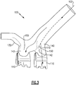
- Collecteur d'impact (100) pour un moteur à turbine à gaz (20), le collecteur d'impact (100) comprenant un passage d'entrée de fluide (120) et au moins une sortie d'écoulement (130),
caractérisé en ce que :
le collecteur d'impact (100) comprend en outre une chambre sous pression (160) comportant une pluralité de lobes (150), chaque lobe (150) comportant une sortie de fluide sous pression et une caractéristique d'amélioration d'écoulement (140, 142) conçue pour minimiser le tourbillon d'un champ d'écoulement à l'intérieur de la chambre sous pression (160), dans lequel la caractéristique d'amélioration d'écoulement (140, 142) comprend une alvéole faisant saillie vers l'intérieur (140) et/ou une bosse faisant saillie vers l'extérieur (142) dans au moins une paroi définissant l'au moins un lobe (150). - Collecteur d'impact (100) selon la revendication 1, dans lequel l'au moins une sortie d'écoulement (130) a une première surface transversale perpendiculaire à une direction attendue d'écoulement de fluide, le passage d'entrée de fluide (120) a une seconde surface transversale perpendiculaire à une direction attendue d'écoulement de fluide, et la première surface transversale est inférieure à la seconde surface transversale.
- Collecteur d'impact (100) selon la revendication 1 ou 2, dans lequel la pluralité de lobes comporte quatre lobes, ou trois lobes.
- Collecteur d'impact (100) selon une quelconque revendication précédente, dans lequel une surface intérieure dudit collecteur (100) est une surface intérieure continue.
- Collecteur d'impact (100) selon la revendication 4, dans lequel ladite surface intérieure continue est conçue pour modifier une direction d'écoulement à travers le collecteur (100) d'un angle (170) dans la plage allant de 35 à 55 degrés.
- Collecteur d'impact (100) selon la revendication 5, dans lequel ladite surface intérieure continue est conçue pour modifier une direction d'écoulement à travers le collecteur d'un angle (170) d'approximativement 45 degrés.
- Collecteur d'impact (100) selon une quelconque revendication précédente, dans lequel le collecteur (100) est une pièce unique construite par l'intermédiaire d'un processus de fabrication additive ou d'un processus de coulée.
- Collecteur d'impact (100) selon l'une quelconque des revendications 1 à 6, dans lequel le collecteur (100) est construit au moins partiellement en pièces en tôle façonnées assemblées.
- Collecteur d'impact (100) selon une quelconque revendication précédente, dans lequel un rapport du rayon de courbure à une largeur de la chambre sous pression (160) au niveau de la courbure est compris dans l'intervalle allant de 2 à 3 pour au moins une partie d'une surface intérieure de la chambre sous pression (160).
- Procédé de fourniture d'un écoulement de refroidissement à un composant d'aéronef comprenant le passage d'un écoulement de refroidissement à travers le collecteur d'impact (100) selon une quelconque revendication précédente.
- Procédé selon la revendication 10, dans lequel le passage de l'écoulement de refroidissement à travers le collecteur (100) comprend en outre la rotation de l'écoulement de fluide à moins de 55 degrés, éventuellement dans la plage allant de 35 à 55 degrés.
- Procédé selon la revendication 10 ou 11, dans lequel le passage de l'écoulement de refroidissement à travers le collecteur (100) comporte la direction de l'écoulement de refroidissement à l'aide d'une surface intérieure continue du collecteur (100).
- Procédé selon la revendication 10, 11 ou 12, dans lequel le passage de l'écoulement de refroidissement à travers le collecteur (100) comporte le fractionnement de l'écoulement de refroidissement, de sorte qu'une partie de l'écoulement de refroidissement passe par chaque lobe (150) dans ladite pluralité de lobes (150).
- Moteur à turbine à gaz (20), comprenant :une section de compresseur (24) définissant partiellement un chemin d'écoulement primaire ;
une section de chambre de combustion (26) reliée de manière fluidique à la section de compresseur (24) et définissant partiellement le chemin d'écoulement primaire ;une section de turbine (28) reliée de manière fluidique à la section de chambre de combustion (26) et définissant partiellement le chemin d'écoulement primaire ; etle collecteur d'impact (100) selon l'une quelconque des revendications 1 à 4. - Moteur à turbine à gaz (20) selon la revendication 14, dans lequel le collecteur de fluide (100) est un composant d'un système de contrôle de jeu actif conçu radialement vers l'extérieur d'au moins l'un d'un étage de compresseur et d'un étage de turbine.
Applications Claiming Priority (1)
| Application Number | Priority Date | Filing Date | Title |
|---|---|---|---|
| US15/148,336 US10329941B2 (en) | 2016-05-06 | 2016-05-06 | Impingement manifold |
Publications (2)
| Publication Number | Publication Date |
|---|---|
| EP3246524A1 EP3246524A1 (fr) | 2017-11-22 |
| EP3246524B1 true EP3246524B1 (fr) | 2019-09-18 |
Family
ID=58692414
Family Applications (1)
| Application Number | Title | Priority Date | Filing Date |
|---|---|---|---|
| EP17169950.7A Active EP3246524B1 (fr) | 2016-05-06 | 2017-05-08 | Collecteur d'impact |
Country Status (2)
| Country | Link |
|---|---|
| US (1) | US10329941B2 (fr) |
| EP (1) | EP3246524B1 (fr) |
Families Citing this family (4)
| Publication number | Priority date | Publication date | Assignee | Title |
|---|---|---|---|---|
| US10329941B2 (en) * | 2016-05-06 | 2019-06-25 | United Technologies Corporation | Impingement manifold |
| US20190170009A1 (en) * | 2017-12-05 | 2019-06-06 | General Electric Company | Turbine engine with clearance control system |
| FR3085719B1 (fr) * | 2018-09-06 | 2021-04-16 | Safran Aircraft Engines | Boitier d'alimentation en air sous pression d'un dispositif de refroidissement par jets d'air |
| US11015475B2 (en) | 2018-12-27 | 2021-05-25 | Rolls-Royce Corporation | Passive blade tip clearance control system for gas turbine engine |
Family Cites Families (42)
| Publication number | Priority date | Publication date | Assignee | Title |
|---|---|---|---|---|
| US2698711A (en) * | 1951-02-06 | 1955-01-04 | United Aircraft Corp | Compressor air bleed closure |
| US4155681A (en) * | 1977-02-14 | 1979-05-22 | General Electric Company | Manifold protection system |
| US4329114A (en) * | 1979-07-25 | 1982-05-11 | The United States Of America As Represented By The Administrator Of The National Aeronautics And Space Administration | Active clearance control system for a turbomachine |
| DE3407945A1 (de) * | 1984-03-03 | 1985-09-05 | MTU Motoren- und Turbinen-Union München GmbH, 8000 München | Verfahren und mittel zur vermeidung der entstehung von titanfeuer |
| US4642024A (en) | 1984-12-05 | 1987-02-10 | United Technologies Corporation | Coolable stator assembly for a rotary machine |
| US4650395A (en) | 1984-12-21 | 1987-03-17 | United Technologies Corporation | Coolable seal segment for a rotary machine |
| US5100291A (en) * | 1990-03-28 | 1992-03-31 | General Electric Company | Impingement manifold |
| US5092735A (en) * | 1990-07-02 | 1992-03-03 | The United States Of America As Represented By The Secretary Of The Air Force | Blade outer air seal cooling system |
| US5116199A (en) * | 1990-12-20 | 1992-05-26 | General Electric Company | Blade tip clearance control apparatus using shroud segment annular support ring thermal expansion |
| US5281085A (en) * | 1990-12-21 | 1994-01-25 | General Electric Company | Clearance control system for separately expanding or contracting individual portions of an annular shroud |
| WO1992017686A1 (fr) * | 1991-04-02 | 1992-10-15 | Rolls-Royce Plc | Carter de turbine |
| US5399066A (en) * | 1993-09-30 | 1995-03-21 | General Electric Company | Integral clearance control impingement manifold and environmental shield |
| FR2750451B1 (fr) * | 1996-06-27 | 1998-08-07 | Snecma | Dispositif de soufflage de gaz de reglage de jeux dans une turbomachine |
| GB9709086D0 (en) * | 1997-05-07 | 1997-06-25 | Rolls Royce Plc | Gas turbine engine cooling apparatus |
| US6367240B1 (en) * | 1998-06-22 | 2002-04-09 | General Electric Company | Air manifold system |
| US6224329B1 (en) * | 1999-01-07 | 2001-05-01 | Siemens Westinghouse Power Corporation | Method of cooling a combustion turbine |
| US6185925B1 (en) * | 1999-02-12 | 2001-02-13 | General Electric Company | External cooling system for turbine frame |
| FR2816352B1 (fr) * | 2000-11-09 | 2003-01-31 | Snecma Moteurs | Ensemble de ventilation d'un anneau de stator |
| US6487491B1 (en) | 2001-11-21 | 2002-11-26 | United Technologies Corporation | System and method of controlling clearance between turbine engine blades and case based on engine components thermal growth model |
| US7052231B2 (en) | 2003-04-28 | 2006-05-30 | General Electric Company | Methods and apparatus for injecting fluids in gas turbine engines |
| US7082770B2 (en) | 2003-12-24 | 2006-08-01 | Martling Vincent C | Flow sleeve for a low NOx combustor |
| FR2867806B1 (fr) * | 2004-03-18 | 2006-06-02 | Snecma Moteurs | Dispositif de pilotage de jeu de turbine a gaz a equilibrage des debits d'air |
| US7513040B2 (en) | 2005-08-31 | 2009-04-07 | United Technologies Corporation | Manufacturable and inspectable cooling microcircuits for blade-outer-air-seals |
| US7597537B2 (en) * | 2005-12-16 | 2009-10-06 | General Electric Company | Thermal control of gas turbine engine rings for active clearance control |
| US7819626B2 (en) * | 2006-10-13 | 2010-10-26 | General Electric Company | Plasma blade tip clearance control |
| US8439629B2 (en) | 2007-03-01 | 2013-05-14 | United Technologies Corporation | Blade outer air seal |
| US8439639B2 (en) | 2008-02-24 | 2013-05-14 | United Technologies Corporation | Filter system for blade outer air seal |
| DE102009011635A1 (de) | 2009-03-04 | 2010-09-09 | Rolls-Royce Deutschland Ltd & Co Kg | Luftleitelement eines Laufspalteinstellungssystems einer Fluggasturbine |
| GB0904118D0 (en) * | 2009-03-11 | 2009-04-22 | Rolls Royce Plc | An impingement cooling arrangement for a gas turbine engine |
| US8092146B2 (en) * | 2009-03-26 | 2012-01-10 | Pratt & Whitney Canada Corp. | Active tip clearance control arrangement for gas turbine engine |
| GB0906059D0 (en) * | 2009-04-08 | 2009-05-20 | Rolls Royce Plc | Thermal control system for turbines |
| US20110044803A1 (en) | 2009-08-18 | 2011-02-24 | Pratt & Whitney Canada Corp. | Blade outer air seal anti-rotation |
| US8769954B2 (en) * | 2009-12-31 | 2014-07-08 | General Electric Company | Frequency-tunable bracketless fluid manifold |
| GB201020418D0 (en) * | 2010-12-02 | 2011-01-19 | Rolls Royce Plc | Fluid impingement arrangement |
| US9316111B2 (en) * | 2011-12-15 | 2016-04-19 | Pratt & Whitney Canada Corp. | Active turbine tip clearance control system |
| US9260974B2 (en) * | 2011-12-16 | 2016-02-16 | General Electric Company | System and method for active clearance control |
| US9316155B2 (en) * | 2013-03-18 | 2016-04-19 | General Electric Company | System for providing fuel to a combustor |
| US9951643B2 (en) | 2013-04-12 | 2018-04-24 | United Technologies Corporation | Rapid response clearance control system with spring assist for gas turbine engine |
| US8910470B2 (en) * | 2013-05-17 | 2014-12-16 | Ford Global Technologies, Llc | Exhaust system having a flow rotation element and method for operation of an exhaust system |
| US20170114667A1 (en) * | 2015-10-23 | 2017-04-27 | General Electric Company | Active clearance control with integral double wall heat shielding |
| US10087772B2 (en) * | 2015-12-21 | 2018-10-02 | General Electric Company | Method and apparatus for active clearance control for high pressure compressors using fan/booster exhaust air |
| US10329941B2 (en) * | 2016-05-06 | 2019-06-25 | United Technologies Corporation | Impingement manifold |
-
2016
- 2016-05-06 US US15/148,336 patent/US10329941B2/en active Active
-
2017
- 2017-05-08 EP EP17169950.7A patent/EP3246524B1/fr active Active
Non-Patent Citations (1)
| Title |
|---|
| None * |
Also Published As
| Publication number | Publication date |
|---|---|
| EP3246524A1 (fr) | 2017-11-22 |
| US20170321568A1 (en) | 2017-11-09 |
| US10329941B2 (en) | 2019-06-25 |
Similar Documents
| Publication | Publication Date | Title |
|---|---|---|
| EP3063374B1 (fr) | Moteur à turbine à gaz et procédé d'exploitation d'un moteur à turbine à gaz | |
| US11661865B2 (en) | Gas turbine engine component | |
| US9920633B2 (en) | Compound fillet for a gas turbine airfoil | |
| US10036271B2 (en) | Gas turbine engine blade outer air seal profile | |
| EP2956627B1 (fr) | Composant de turbine à gaz doté d'une face d'accouplement combinée et d'un refroidissement de plate-forme | |
| US10830070B2 (en) | Endwall countouring trench | |
| EP3091184B1 (fr) | Refroidissement du bord d'attaque d'une aube de turbine | |
| EP3246524B1 (fr) | Collecteur d'impact | |
| EP3061910B1 (fr) | Surface portante de moteur à turbine à gaz et procédé de fabrication correspondant | |
| US9476308B2 (en) | Gas turbine engine serpentine cooling passage with chevrons | |
| EP3009616B1 (fr) | Composant de turbine à gaz avec refroidissement de plate-forme | |
| US10309253B2 (en) | Gas turbine engine blade outer air seal profile | |
| EP3094823B1 (fr) | Composant de moteur à turbine à gaz et moteur à turbine à gaz associé | |
| US20160208620A1 (en) | Gas turbine engine airfoil turbulator for airfoil creep resistance | |
| EP3351731A1 (fr) | Configuration de bord de fuite comportant des rainures de fonderie et des trous de refroidissement par film percés | |
| US20160102561A1 (en) | Gas turbine engine turbine blade tip cooling | |
| EP2993303B1 (fr) | Composant de turbine à gaz avec trou de refroidissement à film avec poche | |
| EP3450685B1 (fr) | Composant de moteur à turbine à gaz | |
| EP3023596B1 (fr) | Plateforme de turbine à refroidissement interne | |
| EP3623587B1 (fr) | Ensemble de profil aérodynamique pour moteur de turbine à gaz | |
| EP3623585B1 (fr) | Couvercle intrados pour un agencement d'aube directrice à cambrure variable pour le compresseur d'un moteur à turbine à gaz | |
| EP3620611B1 (fr) | Support de joint d'air externe de lame unifié et plateforme de pale | |
| EP3734018B1 (fr) | Joint d'étanchéité pour un composant d'un moteur à turbine à gaz et procédé associé |
Legal Events
| Date | Code | Title | Description |
|---|---|---|---|
| PUAI | Public reference made under article 153(3) epc to a published international application that has entered the european phase |
Free format text: ORIGINAL CODE: 0009012 |
|
| STAA | Information on the status of an ep patent application or granted ep patent |
Free format text: STATUS: THE APPLICATION HAS BEEN PUBLISHED |
|
| AK | Designated contracting states |
Kind code of ref document: A1 Designated state(s): AL AT BE BG CH CY CZ DE DK EE ES FI FR GB GR HR HU IE IS IT LI LT LU LV MC MK MT NL NO PL PT RO RS SE SI SK SM TR |
|
| AX | Request for extension of the european patent |
Extension state: BA ME |
|
| STAA | Information on the status of an ep patent application or granted ep patent |
Free format text: STATUS: REQUEST FOR EXAMINATION WAS MADE |
|
| 17P | Request for examination filed |
Effective date: 20180522 |
|
| RBV | Designated contracting states (corrected) |
Designated state(s): AL AT BE BG CH CY CZ DE DK EE ES FI FR GB GR HR HU IE IS IT LI LT LU LV MC MK MT NL NO PL PT RO RS SE SI SK SM TR |
|
| RIC1 | Information provided on ipc code assigned before grant |
Ipc: F02C 6/08 20060101ALI20180622BHEP Ipc: F01D 11/24 20060101ALI20180622BHEP Ipc: F01D 25/12 20060101ALI20180622BHEP Ipc: F01D 11/20 20060101AFI20180622BHEP |
|
| STAA | Information on the status of an ep patent application or granted ep patent |
Free format text: STATUS: EXAMINATION IS IN PROGRESS |
|
| 17Q | First examination report despatched |
Effective date: 20180808 |
|
| GRAP | Despatch of communication of intention to grant a patent |
Free format text: ORIGINAL CODE: EPIDOSNIGR1 |
|
| STAA | Information on the status of an ep patent application or granted ep patent |
Free format text: STATUS: GRANT OF PATENT IS INTENDED |
|
| INTG | Intention to grant announced |
Effective date: 20190326 |
|
| GRAS | Grant fee paid |
Free format text: ORIGINAL CODE: EPIDOSNIGR3 |
|
| GRAA | (expected) grant |
Free format text: ORIGINAL CODE: 0009210 |
|
| STAA | Information on the status of an ep patent application or granted ep patent |
Free format text: STATUS: THE PATENT HAS BEEN GRANTED |
|
| AK | Designated contracting states |
Kind code of ref document: B1 Designated state(s): AL AT BE BG CH CY CZ DE DK EE ES FI FR GB GR HR HU IE IS IT LI LT LU LV MC MK MT NL NO PL PT RO RS SE SI SK SM TR |
|
| REG | Reference to a national code |
Ref country code: GB Ref legal event code: FG4D |
|
| REG | Reference to a national code |
Ref country code: CH Ref legal event code: EP |
|
| REG | Reference to a national code |
Ref country code: DE Ref legal event code: R096 Ref document number: 602017007097 Country of ref document: DE |
|
| REG | Reference to a national code |
Ref country code: AT Ref legal event code: REF Ref document number: 1181548 Country of ref document: AT Kind code of ref document: T Effective date: 20191015 |
|
| REG | Reference to a national code |
Ref country code: IE Ref legal event code: FG4D |
|
| REG | Reference to a national code |
Ref country code: NL Ref legal event code: MP Effective date: 20190918 |
|
| PG25 | Lapsed in a contracting state [announced via postgrant information from national office to epo] |
Ref country code: HR Free format text: LAPSE BECAUSE OF FAILURE TO SUBMIT A TRANSLATION OF THE DESCRIPTION OR TO PAY THE FEE WITHIN THE PRESCRIBED TIME-LIMIT Effective date: 20190918 Ref country code: LT Free format text: LAPSE BECAUSE OF FAILURE TO SUBMIT A TRANSLATION OF THE DESCRIPTION OR TO PAY THE FEE WITHIN THE PRESCRIBED TIME-LIMIT Effective date: 20190918 Ref country code: NO Free format text: LAPSE BECAUSE OF FAILURE TO SUBMIT A TRANSLATION OF THE DESCRIPTION OR TO PAY THE FEE WITHIN THE PRESCRIBED TIME-LIMIT Effective date: 20191218 Ref country code: BG Free format text: LAPSE BECAUSE OF FAILURE TO SUBMIT A TRANSLATION OF THE DESCRIPTION OR TO PAY THE FEE WITHIN THE PRESCRIBED TIME-LIMIT Effective date: 20191218 Ref country code: FI Free format text: LAPSE BECAUSE OF FAILURE TO SUBMIT A TRANSLATION OF THE DESCRIPTION OR TO PAY THE FEE WITHIN THE PRESCRIBED TIME-LIMIT Effective date: 20190918 Ref country code: SE Free format text: LAPSE BECAUSE OF FAILURE TO SUBMIT A TRANSLATION OF THE DESCRIPTION OR TO PAY THE FEE WITHIN THE PRESCRIBED TIME-LIMIT Effective date: 20190918 |
|
| REG | Reference to a national code |
Ref country code: LT Ref legal event code: MG4D |
|
| PG25 | Lapsed in a contracting state [announced via postgrant information from national office to epo] |
Ref country code: LV Free format text: LAPSE BECAUSE OF FAILURE TO SUBMIT A TRANSLATION OF THE DESCRIPTION OR TO PAY THE FEE WITHIN THE PRESCRIBED TIME-LIMIT Effective date: 20190918 Ref country code: RS Free format text: LAPSE BECAUSE OF FAILURE TO SUBMIT A TRANSLATION OF THE DESCRIPTION OR TO PAY THE FEE WITHIN THE PRESCRIBED TIME-LIMIT Effective date: 20190918 Ref country code: GR Free format text: LAPSE BECAUSE OF FAILURE TO SUBMIT A TRANSLATION OF THE DESCRIPTION OR TO PAY THE FEE WITHIN THE PRESCRIBED TIME-LIMIT Effective date: 20191219 Ref country code: AL Free format text: LAPSE BECAUSE OF FAILURE TO SUBMIT A TRANSLATION OF THE DESCRIPTION OR TO PAY THE FEE WITHIN THE PRESCRIBED TIME-LIMIT Effective date: 20190918 |
|
| REG | Reference to a national code |
Ref country code: AT Ref legal event code: MK05 Ref document number: 1181548 Country of ref document: AT Kind code of ref document: T Effective date: 20190918 |
|
| PG25 | Lapsed in a contracting state [announced via postgrant information from national office to epo] |
Ref country code: AT Free format text: LAPSE BECAUSE OF FAILURE TO SUBMIT A TRANSLATION OF THE DESCRIPTION OR TO PAY THE FEE WITHIN THE PRESCRIBED TIME-LIMIT Effective date: 20190918 Ref country code: NL Free format text: LAPSE BECAUSE OF FAILURE TO SUBMIT A TRANSLATION OF THE DESCRIPTION OR TO PAY THE FEE WITHIN THE PRESCRIBED TIME-LIMIT Effective date: 20190918 Ref country code: EE Free format text: LAPSE BECAUSE OF FAILURE TO SUBMIT A TRANSLATION OF THE DESCRIPTION OR TO PAY THE FEE WITHIN THE PRESCRIBED TIME-LIMIT Effective date: 20190918 Ref country code: PT Free format text: LAPSE BECAUSE OF FAILURE TO SUBMIT A TRANSLATION OF THE DESCRIPTION OR TO PAY THE FEE WITHIN THE PRESCRIBED TIME-LIMIT Effective date: 20200120 Ref country code: RO Free format text: LAPSE BECAUSE OF FAILURE TO SUBMIT A TRANSLATION OF THE DESCRIPTION OR TO PAY THE FEE WITHIN THE PRESCRIBED TIME-LIMIT Effective date: 20190918 Ref country code: IT Free format text: LAPSE BECAUSE OF FAILURE TO SUBMIT A TRANSLATION OF THE DESCRIPTION OR TO PAY THE FEE WITHIN THE PRESCRIBED TIME-LIMIT Effective date: 20190918 Ref country code: PL Free format text: LAPSE BECAUSE OF FAILURE TO SUBMIT A TRANSLATION OF THE DESCRIPTION OR TO PAY THE FEE WITHIN THE PRESCRIBED TIME-LIMIT Effective date: 20190918 Ref country code: ES Free format text: LAPSE BECAUSE OF FAILURE TO SUBMIT A TRANSLATION OF THE DESCRIPTION OR TO PAY THE FEE WITHIN THE PRESCRIBED TIME-LIMIT Effective date: 20190918 |
|
| PG25 | Lapsed in a contracting state [announced via postgrant information from national office to epo] |
Ref country code: IS Free format text: LAPSE BECAUSE OF FAILURE TO SUBMIT A TRANSLATION OF THE DESCRIPTION OR TO PAY THE FEE WITHIN THE PRESCRIBED TIME-LIMIT Effective date: 20200224 Ref country code: SK Free format text: LAPSE BECAUSE OF FAILURE TO SUBMIT A TRANSLATION OF THE DESCRIPTION OR TO PAY THE FEE WITHIN THE PRESCRIBED TIME-LIMIT Effective date: 20190918 Ref country code: CZ Free format text: LAPSE BECAUSE OF FAILURE TO SUBMIT A TRANSLATION OF THE DESCRIPTION OR TO PAY THE FEE WITHIN THE PRESCRIBED TIME-LIMIT Effective date: 20190918 Ref country code: SM Free format text: LAPSE BECAUSE OF FAILURE TO SUBMIT A TRANSLATION OF THE DESCRIPTION OR TO PAY THE FEE WITHIN THE PRESCRIBED TIME-LIMIT Effective date: 20190918 |
|
| REG | Reference to a national code |
Ref country code: DE Ref legal event code: R097 Ref document number: 602017007097 Country of ref document: DE |
|
| PLBE | No opposition filed within time limit |
Free format text: ORIGINAL CODE: 0009261 |
|
| STAA | Information on the status of an ep patent application or granted ep patent |
Free format text: STATUS: NO OPPOSITION FILED WITHIN TIME LIMIT |
|
| PG2D | Information on lapse in contracting state deleted |
Ref country code: IS |
|
| PG25 | Lapsed in a contracting state [announced via postgrant information from national office to epo] |
Ref country code: DK Free format text: LAPSE BECAUSE OF FAILURE TO SUBMIT A TRANSLATION OF THE DESCRIPTION OR TO PAY THE FEE WITHIN THE PRESCRIBED TIME-LIMIT Effective date: 20190918 Ref country code: IS Free format text: LAPSE BECAUSE OF FAILURE TO SUBMIT A TRANSLATION OF THE DESCRIPTION OR TO PAY THE FEE WITHIN THE PRESCRIBED TIME-LIMIT Effective date: 20200119 |
|
| 26N | No opposition filed |
Effective date: 20200619 |
|
| PG25 | Lapsed in a contracting state [announced via postgrant information from national office to epo] |
Ref country code: SI Free format text: LAPSE BECAUSE OF FAILURE TO SUBMIT A TRANSLATION OF THE DESCRIPTION OR TO PAY THE FEE WITHIN THE PRESCRIBED TIME-LIMIT Effective date: 20190918 |
|
| PG25 | Lapsed in a contracting state [announced via postgrant information from national office to epo] |
Ref country code: LI Free format text: LAPSE BECAUSE OF NON-PAYMENT OF DUE FEES Effective date: 20200531 Ref country code: CH Free format text: LAPSE BECAUSE OF NON-PAYMENT OF DUE FEES Effective date: 20200531 Ref country code: MC Free format text: LAPSE BECAUSE OF FAILURE TO SUBMIT A TRANSLATION OF THE DESCRIPTION OR TO PAY THE FEE WITHIN THE PRESCRIBED TIME-LIMIT Effective date: 20190918 |
|
| REG | Reference to a national code |
Ref country code: BE Ref legal event code: MM Effective date: 20200531 |
|
| PG25 | Lapsed in a contracting state [announced via postgrant information from national office to epo] |
Ref country code: LU Free format text: LAPSE BECAUSE OF NON-PAYMENT OF DUE FEES Effective date: 20200508 |
|
| PG25 | Lapsed in a contracting state [announced via postgrant information from national office to epo] |
Ref country code: IE Free format text: LAPSE BECAUSE OF NON-PAYMENT OF DUE FEES Effective date: 20200508 |
|
| PG25 | Lapsed in a contracting state [announced via postgrant information from national office to epo] |
Ref country code: BE Free format text: LAPSE BECAUSE OF NON-PAYMENT OF DUE FEES Effective date: 20200531 |
|
| PG25 | Lapsed in a contracting state [announced via postgrant information from national office to epo] |
Ref country code: TR Free format text: LAPSE BECAUSE OF FAILURE TO SUBMIT A TRANSLATION OF THE DESCRIPTION OR TO PAY THE FEE WITHIN THE PRESCRIBED TIME-LIMIT Effective date: 20190918 Ref country code: MT Free format text: LAPSE BECAUSE OF FAILURE TO SUBMIT A TRANSLATION OF THE DESCRIPTION OR TO PAY THE FEE WITHIN THE PRESCRIBED TIME-LIMIT Effective date: 20190918 Ref country code: CY Free format text: LAPSE BECAUSE OF FAILURE TO SUBMIT A TRANSLATION OF THE DESCRIPTION OR TO PAY THE FEE WITHIN THE PRESCRIBED TIME-LIMIT Effective date: 20190918 |
|
| PG25 | Lapsed in a contracting state [announced via postgrant information from national office to epo] |
Ref country code: MK Free format text: LAPSE BECAUSE OF FAILURE TO SUBMIT A TRANSLATION OF THE DESCRIPTION OR TO PAY THE FEE WITHIN THE PRESCRIBED TIME-LIMIT Effective date: 20190918 |
|
| REG | Reference to a national code |
Ref country code: DE Ref legal event code: R081 Ref document number: 602017007097 Country of ref document: DE Owner name: RAYTHEON TECHNOLOGIES CORPORATION (N.D.GES.D.S, US Free format text: FORMER OWNER: UNITED TECHNOLOGIES CORPORATION, FARMINGTON, CONN., US |
|
| P01 | Opt-out of the competence of the unified patent court (upc) registered |
Effective date: 20230520 |
|
| PGFP | Annual fee paid to national office [announced via postgrant information from national office to epo] |
Ref country code: FR Payment date: 20230420 Year of fee payment: 7 Ref country code: DE Payment date: 20230419 Year of fee payment: 7 |
|
| PGFP | Annual fee paid to national office [announced via postgrant information from national office to epo] |
Ref country code: GB Payment date: 20230420 Year of fee payment: 7 |