EP3246519B1 - Composant refroidi activement - Google Patents
Composant refroidi activement Download PDFInfo
- Publication number
- EP3246519B1 EP3246519B1 EP17168136.4A EP17168136A EP3246519B1 EP 3246519 B1 EP3246519 B1 EP 3246519B1 EP 17168136 A EP17168136 A EP 17168136A EP 3246519 B1 EP3246519 B1 EP 3246519B1
- Authority
- EP
- European Patent Office
- Prior art keywords
- holes
- impingement
- hole
- angled film
- angled
- Prior art date
- Legal status (The legal status is an assumption and is not a legal conclusion. Google has not performed a legal analysis and makes no representation as to the accuracy of the status listed.)
- Active
Links
Images


Classifications
-
- F—MECHANICAL ENGINEERING; LIGHTING; HEATING; WEAPONS; BLASTING
- F01—MACHINES OR ENGINES IN GENERAL; ENGINE PLANTS IN GENERAL; STEAM ENGINES
- F01D—NON-POSITIVE DISPLACEMENT MACHINES OR ENGINES, e.g. STEAM TURBINES
- F01D5/00—Blades; Blade-carrying members; Heating, heat-insulating, cooling or antivibration means on the blades or the members
- F01D5/12—Blades
- F01D5/14—Form or construction
- F01D5/18—Hollow blades, i.e. blades with cooling or heating channels or cavities; Heating, heat-insulating or cooling means on blades
- F01D5/187—Convection cooling
-
- F—MECHANICAL ENGINEERING; LIGHTING; HEATING; WEAPONS; BLASTING
- F01—MACHINES OR ENGINES IN GENERAL; ENGINE PLANTS IN GENERAL; STEAM ENGINES
- F01D—NON-POSITIVE DISPLACEMENT MACHINES OR ENGINES, e.g. STEAM TURBINES
- F01D25/00—Component parts, details, or accessories, not provided for in, or of interest apart from, other groups
- F01D25/08—Cooling; Heating; Heat-insulation
- F01D25/12—Cooling
-
- F—MECHANICAL ENGINEERING; LIGHTING; HEATING; WEAPONS; BLASTING
- F01—MACHINES OR ENGINES IN GENERAL; ENGINE PLANTS IN GENERAL; STEAM ENGINES
- F01D—NON-POSITIVE DISPLACEMENT MACHINES OR ENGINES, e.g. STEAM TURBINES
- F01D5/00—Blades; Blade-carrying members; Heating, heat-insulating, cooling or antivibration means on the blades or the members
- F01D5/12—Blades
- F01D5/14—Form or construction
- F01D5/18—Hollow blades, i.e. blades with cooling or heating channels or cavities; Heating, heat-insulating or cooling means on blades
- F01D5/186—Film cooling
-
- F—MECHANICAL ENGINEERING; LIGHTING; HEATING; WEAPONS; BLASTING
- F01—MACHINES OR ENGINES IN GENERAL; ENGINE PLANTS IN GENERAL; STEAM ENGINES
- F01D—NON-POSITIVE DISPLACEMENT MACHINES OR ENGINES, e.g. STEAM TURBINES
- F01D9/00—Stators
- F01D9/02—Nozzles; Nozzle boxes; Stator blades; Guide conduits, e.g. individual nozzles
- F01D9/04—Nozzles; Nozzle boxes; Stator blades; Guide conduits, e.g. individual nozzles forming ring or sector
- F01D9/041—Nozzles; Nozzle boxes; Stator blades; Guide conduits, e.g. individual nozzles forming ring or sector using blades
-
- F—MECHANICAL ENGINEERING; LIGHTING; HEATING; WEAPONS; BLASTING
- F05—INDEXING SCHEMES RELATING TO ENGINES OR PUMPS IN VARIOUS SUBCLASSES OF CLASSES F01-F04
- F05D—INDEXING SCHEME FOR ASPECTS RELATING TO NON-POSITIVE-DISPLACEMENT MACHINES OR ENGINES, GAS-TURBINES OR JET-PROPULSION PLANTS
- F05D2220/00—Application
- F05D2220/30—Application in turbines
- F05D2220/32—Application in turbines in gas turbines
-
- F—MECHANICAL ENGINEERING; LIGHTING; HEATING; WEAPONS; BLASTING
- F05—INDEXING SCHEMES RELATING TO ENGINES OR PUMPS IN VARIOUS SUBCLASSES OF CLASSES F01-F04
- F05D—INDEXING SCHEME FOR ASPECTS RELATING TO NON-POSITIVE-DISPLACEMENT MACHINES OR ENGINES, GAS-TURBINES OR JET-PROPULSION PLANTS
- F05D2260/00—Function
- F05D2260/20—Heat transfer, e.g. cooling
- F05D2260/201—Heat transfer, e.g. cooling by impingement of a fluid
-
- F—MECHANICAL ENGINEERING; LIGHTING; HEATING; WEAPONS; BLASTING
- F05—INDEXING SCHEMES RELATING TO ENGINES OR PUMPS IN VARIOUS SUBCLASSES OF CLASSES F01-F04
- F05D—INDEXING SCHEME FOR ASPECTS RELATING TO NON-POSITIVE-DISPLACEMENT MACHINES OR ENGINES, GAS-TURBINES OR JET-PROPULSION PLANTS
- F05D2260/00—Function
- F05D2260/20—Heat transfer, e.g. cooling
- F05D2260/202—Heat transfer, e.g. cooling by film cooling
-
- F—MECHANICAL ENGINEERING; LIGHTING; HEATING; WEAPONS; BLASTING
- F05—INDEXING SCHEMES RELATING TO ENGINES OR PUMPS IN VARIOUS SUBCLASSES OF CLASSES F01-F04
- F05D—INDEXING SCHEME FOR ASPECTS RELATING TO NON-POSITIVE-DISPLACEMENT MACHINES OR ENGINES, GAS-TURBINES OR JET-PROPULSION PLANTS
- F05D2260/00—Function
- F05D2260/20—Heat transfer, e.g. cooling
- F05D2260/204—Heat transfer, e.g. cooling by the use of microcircuits
-
- F—MECHANICAL ENGINEERING; LIGHTING; HEATING; WEAPONS; BLASTING
- F05—INDEXING SCHEMES RELATING TO ENGINES OR PUMPS IN VARIOUS SUBCLASSES OF CLASSES F01-F04
- F05D—INDEXING SCHEME FOR ASPECTS RELATING TO NON-POSITIVE-DISPLACEMENT MACHINES OR ENGINES, GAS-TURBINES OR JET-PROPULSION PLANTS
- F05D2260/00—Function
- F05D2260/20—Heat transfer, e.g. cooling
- F05D2260/221—Improvement of heat transfer
- F05D2260/2212—Improvement of heat transfer by creating turbulence
-
- F—MECHANICAL ENGINEERING; LIGHTING; HEATING; WEAPONS; BLASTING
- F05—INDEXING SCHEMES RELATING TO ENGINES OR PUMPS IN VARIOUS SUBCLASSES OF CLASSES F01-F04
- F05D—INDEXING SCHEME FOR ASPECTS RELATING TO NON-POSITIVE-DISPLACEMENT MACHINES OR ENGINES, GAS-TURBINES OR JET-PROPULSION PLANTS
- F05D2260/00—Function
- F05D2260/20—Heat transfer, e.g. cooling
- F05D2260/221—Improvement of heat transfer
- F05D2260/2214—Improvement of heat transfer by increasing the heat transfer surface
- F05D2260/22141—Improvement of heat transfer by increasing the heat transfer surface using fins or ribs
-
- Y—GENERAL TAGGING OF NEW TECHNOLOGICAL DEVELOPMENTS; GENERAL TAGGING OF CROSS-SECTIONAL TECHNOLOGIES SPANNING OVER SEVERAL SECTIONS OF THE IPC; TECHNICAL SUBJECTS COVERED BY FORMER USPC CROSS-REFERENCE ART COLLECTIONS [XRACs] AND DIGESTS
- Y02—TECHNOLOGIES OR APPLICATIONS FOR MITIGATION OR ADAPTATION AGAINST CLIMATE CHANGE
- Y02T—CLIMATE CHANGE MITIGATION TECHNOLOGIES RELATED TO TRANSPORTATION
- Y02T50/00—Aeronautics or air transport
- Y02T50/60—Efficient propulsion technologies, e.g. for aircraft
Definitions
- Gas turbine engine airfoils particularly those that require cooling, remain an area of interest.
- Some existing systems have various shortcomings, drawbacks, and disadvantages relative to certain applications. Accordingly, there remains a need for further contributions in this area of technology.
- the invention is an actively cooled component, comprising:
- the invention provides an airfoil, comprising:
- the invention provides a method of actively cooling a component, comprising, providing a pressure differential to drive a flow of coolant media; driving the flow of coolant media through an aperture in a cold wall of the component, into a channel having a plurality of apertures aligned along a first axis and a plurality of angled film holes aligned along a second axis parallel to the first axis, where the flow of coolant media impinges on an inner surface of a hot wall of the component;
- the component may have a body comprising at least one internal channel adapted for a flow of a cooling media therein.
- the internal channel may have two side walls separating a cold inner surface and a hot inner surface.
- the cold inner surface may have two impingement holes in fluid communication with a cooling media source, allowing for ingress of the cooling media into the internal channel.
- the hot inner surface may have one angled film hole in fluid communication with a hot outer surface, allowing for egress of the cooling media out of the internal channel.
- the first and second side walls may enclose a length of the internal channel along which the angled film hole is located between the two impingement holes.
- the angled film hole may be considered a first angled film hole, and the hot inner surface may further comprise a second angled film hole also in fluid communication with the hot outer surface. Furthermore, the two side walls may enclose a length of the channel along which the first impingement hole is located between the first and second angled film holes.
- the actively cooled component may further comprise a plurality of impingement holes and a plurality of angled film holes.
- the plurality of impingement holes may be aligned along a first axis and the plurality of angled film holes may be aligned along a second axis parallel to the first axis.
- the impingement holes may direct the cooling media at the hot inner surface to create a turbulent flow
- the angled film hole may be angled to direct the cooling media along the hot outer surface to create a laminar film.
- the angled film hole may be at an acute angle less than or equal to 45 degrees relative to the hot outer surface.
- the plurality of film holes may be clocked in any direction, for example, the film holes may align with the gas path flow field. The film holes may not necessarily point in the same direction and can be individually tailored.
- the actively cooled component may further comprise a plurality of pairs of impingement holes.
- Each pair of impingement holes may comprise an "L" impingement hole aligned along a first axis, and an "R” impingement hole aligned along a second axis parallel to the first axis.
- the actively cooled component may further comprise a plurality of angled film holes which may be aligned along a third axis parallel to the first and second axes. The third axis may be located between the first and second axes.
- the actively cooled component may further comprise a plurality of impingement holes and a plurality of angled film holes. There may be at least twice as many impingement holes as angled film holes.
- the component may further comprise a plurality of internal channels, each having only one angled film hole and at least two impingement holes.
- the actively cooled component may be located at a leading edge of an airfoil.
- the actively cooled component may further comprise a plurality of impingement holes and a plurality of angled film holes.
- the internal channel may have a first portion with a ratio of impingement holes to angled film holes of at least two-to-one, and may have a second portion with a ratio of impingement holes to angled film homes of one-to-one.
- a first impingement hole may be located closer to a first side wall than a second side wall, while a second impingement hole may be located closer to the second side wall than the first side wall.
- first impingement hole may be located closer to the first angled film hole than the second angled film hole
- second impingement hole may be located closer to the second angled film hole than the first angled film hole
- Gas turbine engines of the axial flow type may include turbines that are made up of axially alternate annular arrays of radially extending stator airfoil vanes and rotary airfoil blades.
- the demands of modern gas turbine engines may require that the gases that flow through, and thereby drive, the turbine are at extremely high temperature. As the gases flow through the turbine, their temperature progressively falls as they drive the turbine. However, notwithstanding this, the gas temperatures in the higher pressure regions of the turbine may be so high that some form of airfoil cooling may be required.
- Turbine airfoils both blades and vanes, may be cooled internally with a gas or a liquid, such as air that has been tapped from the gas turbine engine's compressor. Using engine compressor air in this manner may, however, carry a penalty in terms of the overall operating efficiency of the engine.
- cooling of the components of the gas turbine engine is preferably accomplished with a minimum amount of cooling media, since the cooling media may be a working fluid, which has been extracted from the compressor, and its loss from the gas flow may rapidly reduce engine efficiency.
- the larger the percentage of air taken from the compressor the greater the adverse effect there is upon overall engine operating efficiency.
- Engines may be designed to simultaneously operate within a specified temperature range, while minimizing the amount of cooling media extracted from the compressor. If these design parameters are not satisfied, a corresponding structural degradation of the engine components may result, or the efficiency of the engine may be reduced because an excessive quantity of cooling media was extracted from the compressor.
- Methods of cooling may include convection cooling and film cooling.
- Convection cooling generally refers to a technique of transferring heat from a surface of an object to the environment by the movement of matter, for example, cooling internal surfaces of the component (e.g., airfoil) by directing a steady flow of pressurized cooling media through a network of internal passageways of the component.
- the pressurized cooling media may enter the passageways via cooler inlet holes and exiting through hotter exit holes. This may provide for convective heat transfer from the walls of the component to the cooling media.
- the design of airfoils may include internal channels for the flow of cooling air.
- Such channels may provide convection cooling such that air is drawn from a hollow airfoil interior (e.g., reservoir of cooled air) and through small inlet holes into the channels (e.g., radially extending passages or impingement holes) where the air may absorb heat from the surfaces of the channels.
- Some of the air may be exhausted through small exit holes that provide fluid communication between the channels and the airfoil external surface. As the air is exhausted from the holes, it may form a film on the airfoil external surface that provides additional airfoil cooling via film cooling.
- Film cooling generally refers to a technique of cooling an external surface of the component (e.g., airfoil) that is being heated by the high temperature gas, and may involve directing a flow of relatively cool media, such as air, along the component's external surface.
- the cooling media may function as an insulating layer to reduce the unwanted heating of the external surface of the component by the flow of high temperature gas.
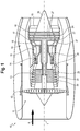
- FIG. 1 illustrates a gas turbine engine 10 which may include a compressor, a combustor, and a power turbine.
- the three components may be integrated together to produce a flight propulsion engine, for example, for use in helicopters, airplanes, missiles, and any other substantially similar devices.
- the engine 10 may include, in the flow direction, an air inlet 11, a fan 12 rotating inside a casing, an intermediate-pressure compressor 13, a high-pressure compressor 14, a combustion chamber 15, a high-pressure turbine 16, an intermediate-pressure turbine 17 and a low-pressure turbine 18 as well as an exhaust nozzle 19, all of which being arranged about a center engine axis 1.
- the intermediate-pressure compressor 13 and the high-pressure compressor 14 may each include several stages, of which each has an arrangement extending in the circumferential direction of fixed and stationary guide vanes 20, generally referred to as stator vanes and projecting radially inwards from the engine casing 21 in an annular flow duct through the compressors 13 and 14.
- the compressors furthermore may have an arrangement of compressor rotor blades 22 which project radially outwards from a rotatable drum or disk 26 linked to hubs 27 of the high-pressure turbine 16 or the intermediate-pressure turbine 17, respectively.
- the stationary guide vanes 20, compressor rotor blades 22, fixed stator vanes 23, and turbine blades 24 may collectively be referred to as airfoils 100 (see FIG. 2 ), and hereinafter this application will refer to blades and/or vanes as airfoils 100, unless specifically stated otherwise in the text. As discussed later in this application, at least a portion of the airfoils 100 may have a dual-wall cooling configuration to improve the cooling.
- the gas turbine engine airfoils 100 are formed of a heat resistant superalloy composition.
- superalloy compositions such as but not limited to nickel based or cobalt based compositions. Most superalloy compositions of interest are complicated mixtures of nickel, chromium, aluminum and other select elements.
- the airfoils may be of a unitary cast configuration, and/or an assembly of cast components, and/or an assembly of cast and wrought components.
- the airfoils may have an equiax, directionally solidified or a single crystal alloy structure.
- the gas turbine engine airfoils 100 are of a cast single crystal single structure.
- the products are formed of a metallic material, or an intermetallic material or a ceramic material.
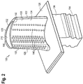
- FIG. 2 illustrates a perspective view of one example of an airfoil 100 of a gas turbine engine 10.
- the airfoil 100 may have as principal regions an airfoil portion 102, a root portion 104, and a shank portion 106 extending between the airfoil portion 102 and the root portion 104.
- the shank portion 106 may have a central conduit (not shown) formed therein which is in fluid communication with a hollow cavity/passageway 210 (see also FIG. 3 ) within the airfoil 100.
- FIG. 3 illustrates a cutaway perspective view of an example airfoil 100.
- Airfoil 100 may have a cover member 150, a spar member 160, and a hollow cavity/passageway 210 extending therethrough (see also FIG. 2 ).
- the hollow cavity 210 may be in fluid communication with the central conduit of the shank portion 106, which itself may be in fluid communication with cooling media from the compressor. These connected passageways may act as a cooling media reservoir.
- the spar member 160 may be exposed to the cold hollow cavity 210, and thus have a cold outer surface 162 forming at least a portion of a surface of the hollow cavity 210, and a cold inner surface forming at least a portion of a cold inner surface 164 of the internal channel 240.
- the internal channel 240 may have a first side wall 250 and a second side wall 252, both separating the cold inner surface 164 and the hot inner surface 154 of the spar member 160 and cover member 150, respectively.
- the spar member 160 may further comprise a plurality of impingement holes 230 in fluid communication with the internal channel 240 and the cold outer surface 162 of the spar member 150 (including hollow cavity 210 and apertures 220).
- the cover member 150 may further comprise a plurality of angled film holes 260 (e.g., exit holes 140) in fluid communication with the internal channel 240 and the hot outer surface 152 of the cover member 150 (e.g., outer surface 124 of airfoil 100).
- the cover member 150 may be a thin walled member, and may have a wall thickness in the range of about 0.35 millimeters to 0.65 millimeters. In another example the cover member 150 may have a wall thickness of about 0.51 millimeters. However, other wall thicknesses are contemplated herein.
- each internal channel 240 may comprise a plurality of apertures 220, a plurality of impingement holes 230, and a plurality of angled film holes 260 (e.g., a plurality of exit holes 140).
- the plurality of apertures 220 and impingement holes 230 may be formed through the spar member 160 to allow the flow of pressurized cooling media into the plurality of internal channels 240.
- the cooling media may flow through the internal channel 240 and absorb heat via convection from the hot inner surface 154 of the cover member 150 and the side walls 250 and 252.
- the exit holes 140 in the hot inner surface 154 may comprise a first angled film hole 261 in fluid communication with the hot outer surface 152 of the cover member 150 for egress of the cooling media out of the internal channel 240.
- the first and second side walls 250 and 252, respectively, may enclose a length of the channel along which the first angled film hole 261 is located between the first and second impingement holes 231 and 232, respectively.
- the impingement holes 230, 231, and 232 may appear circular
- the angled film holes 260, 261, and 262 may appear elliptical. This may be a result of the cross-sectional view, wherein the angled film holes are oriented at an acute angle such that they appear elliptical while the impingement holes are oriented at an orthogonal angle such that they appear circular.
- the first side wall 250 and second side wall 252 may have a variety of shapes and contours.
- the first side wall 250 may have a first concave portion 254 relative to the internal channel 240.
- the first side wall 250 may also have a second concave portion 256 intersecting the first concave portion 254, forming a convex intersection point 258 relative to the internal channel 240.
- the first concave portion 254 may have a first radius of curvature
- the second concave portion 256 may have a second radius of curvature different from the first radius of curvature.
- the second side wall 252 may be substantially symmetrical to the first side wall 250, for example, having substantially symmetrical concave portions, convex portions, and respective radii of curvature.
- the cooling media may flow from the hollow cavity 210, through the apertures 220, through first and second impingement holes 231 and 232, respectively, such that the cooling media enters the internal channel 240 and impinges on the hot inner surface 154 (see FIG. 3 ). Primarily driven by a pressure gradient, the cooling media may then flow through the internal channel 240 between the first and second side walls 250 and 252, respectively.
- the shape of the first and second side walls 250 and 252 may cause turbulence in the cooling media flow, for example, caused by the first concave portion 254 with the first radius of curvature, the second concave portion 256 having the second radius of curvature, the convex intersection point 258, and any shapes that may be present on the second side wall 252, for example, the second side wall 252 may be symmetrical to the first side wall 250.
- the cooling media may exit the internal channel 240 through the first angled film hole 261, which may direct the cooling media onto the hot outer surface 152 of the cover member 150 of the airfoil 100 (see FIG. 3 ).
- the cooling media may absorb heat via convective heat transfer from any surface having a higher temperature than the cooling media itself, including the hot inner surface 154, the first side wall 250, the second side wall 252, and the cold inner surface 164.
- the internal channel 240 may further comprise a second angled film hole 262 in fluid communication with the hot outer surface 152 of cover member 150.
- the first and second side walls 250 and 252, respectively, may enclose a length of the internal channel 240 along which the first impingement hole 231 is located between the first and second angled film holes 261 and 262, respectively.
- this length of the internal channel 240 is an alternating pattern, wherein the first impingement hole 231 is spaced between two angled film holes, and the first angled film hole is spaced between two impingement holes.
- internal channels 240 of the airfoil 100 may further comprise a plurality of impingement holes 230 and a plurality of angled film holes 260.
- the of impingement holes may be aligned along a first impingement hole axis 236, and wherein the plurality of angled film holes may be aligned along a first angled film hole axis 266.
- the first impingement hole axis 236 may be parallel to the first angled film hole axis 266.
- the first impingement hole axis 236 may be identical to the first angled film hole axis 266.
- the plurality of impingement holes 230 and angled film holes 260 may facilitate cooling.
- the concave and convex shape of the side walls 250 and 252 may create a turbulent flow.
- This turbulent flow may encourage mixing of the cooling media and increased heat transfer.
- the cooling media may remain in the internal channel 240 for a longer duration, increasing heat transfer from the surfaces of the internal channels 240. This may result in increased engine efficiency by reducing the amount of cooling media extracted from the compressor to cool the airfoil 100.
- the turbulent flow and increased mixing of the cooling media may decrease the fraction of cooling media that enters through a given impingement hole and exits through the next angled film hole, again increasing heat transfer and engine efficiency.
- Cooling media may flow through at least one of plurality of angled film holes 260 (including the first and second angled film holes 261 and 262).
- the angled film hole(s) may be angled to direct the cooling media along the hot outer surface 152 to create a laminar film for film cooling.
- This laminar film of cooling media may function as an insulating layer to reduce the unwanted heating of the hot outer surface 152 of the cover member 150 (and thus the outer surface 124 of the airfoil 100) by the flow of high temperature gas.
- the angle of the angled film hole(s) may be an acute angle, for example, less than or equal to 45 degrees relative to the hot outer surface 152. In some examples, this angle may be between 25-35 degrees.
- the optimal angle may differ based on engine and airfoils designs, however, in general the cooling media forms a suitable boundary layer to insulate the hot outer surface 152.
- the plurality of film holes 260 may be clocked in any direction, for example, the film holes 260 may align with the gas path flow field.
- the film holes 260 may not necessarily point in the same direction and can be individually tailored.
- FIG. 5 illustrates a cross-sectional view of one of the example internal channels 240 of an airfoil 100 shown in FIG. 3 .
- the internal channel 240 may further comprise a plurality of pairs of impingement holes 235, wherein each pair of impingement holes comprises an "L" impingement hole 238 and an "R” impingement hole 239.
- the plurality of "L” impingement holes 238 may be aligned along a first impingement hole axis 236.
- the plurality of "R” impingement holes 239 may be aligned along a second impingement hole axis 237.
- the first and second impingement hole axes 236 and 237, respectively, may be parallel to one another.
- the internal channel 240 may further comprise a plurality of angled film holes 260 aligned along a first angled film hole axis 266.
- the first angled film hole axis 266 may be parallel to the first and second impingement hole axes 236 and 237, respectively.
- the first angled film hole axis 266 may be located between the first and second impingement hole axes 236 and 237, respectively.
- the impingement holes may appear circular, whereas the angled film holes may appear elliptical due to their acute angle.
- each of the plurality of pairs of impingement holes 235 may have just one corresponding angled film hole in the plurality of angled film holes 260, resulting in a two-to-one ratio.
- the first and second side walls 250 and 252 may enclose a length of the channel along which the first and second impingement holes 231 and 232 are located between the first and second angled film holes 261 and 262.
- the first impingement hole 231 may be located closer to the first side wall 250 than the second side wall 252, while the second impingement hole 232 may be located closer to the second side wall 252 than the first side wall 250.
- the first and second side walls 250 and 252 may have a variety of shapes and contours.
- the first side wall 250 may have a first concave portion 254 relative to the internal channel 240.
- the first side wall 250 may also have a second concave portion 256 intersecting the first concave portion 254, forming a convex intersection point 258 relative to the internal channel 240.
- the first concave portion 254 may have a first radius of curvature
- the second concave portion 256 may have a second radius of curvature different from the first radius of curvature.
- the second side wall 252 may also have concave portions, convex portions, and respective radii of curvature.
- the additional tortuosity ("zig-zag") of the internal channel 240 and the increased number of impingement holes may both facilitate additional cooling, while retaining the cooling properties of the plurality of impingement holes 230 and angled film holes 260.
- "Zig-zag" may be defined as a path that changes direction at regular intervals, for example, alternating ninety-degree turns to the left and right at fixed intervals. Other angles may also fall within this definition, as well as varying intervals.
- the cooling media may flow from an "L" impingement hole 238, towards an "R” impingement hole 239, and towards the next "L” impingement hole 238, towards the next “R” impingement hole 239, and so on.
- This "zig-zag" pattern of tortuous flow may further increase the turbulent flow of cooling media with the internal channel 240 in addition to the turbulence caused by the concave and convex shape of the side walls 250 and 252.
- This increased turbulent flow may further increase mixing of the cooling media and increased heat transfer.
- the cooling media may remain in the internal channel 240 for a longer duration, increasing heat transfer as well as engine efficiency.
- the turbulent flow and increased mixing of the cooling media may decrease the fraction of cooling media that enters through a given impingement hole and exits through the next angled film hole, again increasing heat transfer and engine efficiency.
- the plurality of angled film holes 260 may be angled to direct the cooling media along the hot outer surface 152 to create a laminar film that may function as an insulating layer for film cooling.
- the plurality of film holes 260 may be clocked in any direction, for example, the film holes 260 may align with the gas path flow field.
- the film holes 260 may not necessarily point in the same direction and can be individually tailored.
- FIG. 6 illustrates a perspective view of another example of a plurality of internal channels 240 of an airfoil 100.
- different examples of internal channels 240 may be adjacent to one another within a given airfoil 100.
- the right-most channel has a ratio of impingement holes to angled film holes of one-to-one, whereas the adjacent channel has a higher ratio.
- channel design may differ within a given internal channel 240, forming a hybrid internal channel 242.
- the two left-most channels are hybrid channels 242, each having at least one portion where the ratio of impingement holes to angled film holes is two-to-one and at least one portion where the ratio is one-to-one.
- the angled film holes are not shown in FIG. 6 , though they are understood to be present.
- FIGS. 7-9 illustrate a cross-sectional view and two perspective views, respectively, of another example of an internal channel 240 of an airfoil 100.
- the cover member 150 obstructs the view of certain internal channels 240, while in FIG. 9 the cover member 150 has been hidden from view for illustration purposes. Additionally, in FIG. 9 all but four of the plurality of angled film holes 260 have also been hidden for illustration purposes.
- the internal channel 240 may further comprise a plurality of pairs of impingement holes 235 and a plurality of angled film holes 260. There may be at least twice as many impingement holes as angled film holes.
- the airfoil 100 may further comprise a plurality of internal channels 240.
- Each pair of impingement holes 235 may comprise an "L” impingement hole 238 and an "R” impingement hole 239.
- the plurality of "L” impingement holes 238 may be aligned along a first impingement hole axis 236.
- the plurality of "R” impingement holes 239 may be aligned along a second impingement hole axis 237.
- the first and second impingement hole axes 236 and 237, respectively, may be parallel to one another.
- the internal channel 240 may further comprise a plurality of angled film holes 260 aligned along a first angled film hole axis 266.
- the first angled film hole axis 266 may be parallel to the first and second impingement hole axes 236 and 237, respectively.
- the first angled film hole axis 266 may be located between the first and second impingement hole axes 236 and 237, respectively. As discussed above with respect to FIGS. 4-5 , the impingement holes may appear circular, whereas the angled film holes may appear elliptical due to their acute angle.
- each of the plurality of pairs of impingement holes 235 may have just one corresponding angled film hole in the plurality of angled film holes 260, resulting in a two-to-one ratio.
- the first and second side walls 250 and 252 may enclose a length of the channel along which the first angled film hole 261 is located between the first and second impingement holes 231 and 232.
- the first and second side walls 250 and 252 may have a variety of shapes and contours.
- the first side wall 250 may have a first concave portion 254 relative to the internal channel 240.
- the first side wall 250 may also have a second concave portion 256 intersecting the first concave portion 254, forming a convex intersection point 258 relative to the internal channel 240.
- the first concave portion 254 may have a first radius of curvature
- the second concave portion 256 may have a second radius of curvature different from the first radius of curvature.
- the second side wall 252 may also have concave portions, convex portions, and respective radii of curvature.
- angles of the plurality of angled film holes 260 may not be identical for each of the plurality of internal channels 240.
- the angles of the plurality of angled film holes 260 may alternate such that the angles of the film holes of adjacent channels may be perpendicular to one another. This may provide targeted film cooling on the outer surface 124 of the airfoil 100.
- the plurality of film holes 260 may be clocked in any direction, for example, the film holes 260 may align with the gas path flow field.
- the film holes 260 may not necessarily point in the same direction and can be individually tailored.
- each of the plurality of internal channels 240 may be limited to only one angled film hole.
- the cooling media within each of the plurality of internal channels 240 is "isolated" because it can only flow within the channel and out of a single angled film hole. While the flow within the plurality of internal channels 240 may be turbulent, the lone angled film hole and shorter length in a given internal channel means the cooling media may spend less time mixing. As a result, this channel design and configuration may be ideal for a hotter region of the airfoil 100, for example the leading edge 120, where the higher temperature means that the cooling media absorbs the requisite amount of heat in a shorter time. This may compensate for the reduced mixing time since the heat may be absorbed at a faster rate. Other examples (not shown) may include additional impingement holes.
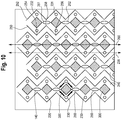
- FIG. 10 illustrates a cross-sectional view of an example including dual cold-feed internal channels 240 of an airfoil 100 where the channels 240 have at least one pedestal-like obstruction.
- the first side wall 250 and second side wall 252 may both separate the cold inner surface 164 (not shown) and the hot inner surface 154 (not shown) of the spar member 160 and cover member 150, respectively (see e.g., FIG. 3 ).
- the apertures 220 in the cold inner surface 164 may comprise a first impingement hole 231 and a second impingement hole 232 both in fluid communication with the hollow cavity 210 (e.g., cooling media source) for ingress of the cooling media into the internal channel 240.
- the exit holes 140 in the hot inner surface 154 may comprise a first angled film hole 261 in fluid communication with the hot outer surface 152 of the cover member 150 for egress of the cooling media out of the internal channel 240.
- the first and second side walls 250 and 252, respectively, may enclose a length of the channel along which the first angled film hole 261 is located between the first and second impingement holes 231 and 232, respectively.
- the impingement holes 230, 231, and 232 may appear circular
- the angled film holes 260, 261, and 262 may appear elliptical. This may be a result of the cross-sectional view, wherein the angled film holes are oriented at an acute angle such that they appear elliptical while the impingement holes are oriented at an orthogonal angle such that they appear circular.
- the first side wall 250 and second side wall 252 may have a series of orthogonal or ninety-degree (90°) turns or intersections.
- the first side wall 250 may have first and second concave points 254 and 256 relative to the internal channel 240. Between these two points, the first side wall 250 may have a first convex point 258 relative to the internal channel 240.
- the second side wall 252 may be substantially symmetrical to the first side wall 250.
- the ninety-degree (90°) turns or intersections may increase turbulent flow of cooling media through the channels 240.
- the of impingement holes 230 may be aligned along a first impingement hole axis 236, and the angled film holes 260 may be aligned along a first angled film hole axis 266.
- the first impingement hole axis 236 may be parallel to the first angled film hole axis 266.
- Each channel 240 may include one or more pedestal structures 300 spanning the height of the channel. The arrows shown in the left-most channel 240 illustrate the flow of a portion of the cooling media from two impingement holes 230 and around one pedestal 300.
- the pedestal 300 may act as an obstruction to the flow of cooling media and may create a turbulent flow.
- This turbulent flow may encourage mixing of the cooling media and increased heat transfer.
- the cooling media may remain in the internal channel 240 for a longer duration, increasing heat transfer from the surfaces of the internal channels 240. This may result in increased engine efficiency by reducing the amount of cooling media extracted from the compressor to cool the airfoil 100.
- the turbulent flow and increased mixing of the cooling media may decrease the fraction of cooling media that enters through a given impingement hole and exits through the next angled film hole, again increasing heat transfer and engine efficiency.
- the concepts described herein, including the designs and configurations of internal channels 240 of an airfoil 100, may be utilized advantageously, for example, in large civil engines having reduced combustor feed pressures, especially in low ⁇ P (change in pressure) locations of the airfoil 100.
- the advantages of these designs include, but are not limited to, increased thermal efficiency and increased hot-side pressure margins (change in pressure between hot outer surface 152 and hot inner surface 154, in particular, the change in pressure across one or more of the plurality of angled film holes 260).
- Advantages may also include maintaining certain design requirements, for example, maintaining minimum wall thickness for casting yields, maintaining minimum hole spacing to meet longevity requirements, and maintaining a minimum footprint to allow close hot side hole spacing for enhanced film effectiveness.
- Another advantage is increased redundancy in the system by having multiple impingement holes and multiple angled film holes. If any hole becomes plugged with debris or otherwise becomes less effective, there are multiple other holes nearby for cooling media to flow through, reducing any negative effect. This may increase the lifespan of an airfoil since regions near any holes plugged with debris may remain within the expected range of operational temperatures. There may also be additional heat transfer due to unsteady effects (e.g., flow may be split unevenly between adjacent impingement holes wherein flow switches rapidly during operation, increasing heat transfer). As discussed throughout this application, the flow of cooling media through the internal channels 240 may also encourage the cooling media to remain within the channels 240 for longer (increased heat transfer), instead of flowing out of the nearest angled film hole.
- the examples disclosed herein and the related designs mitigate ingestion of hot-side air and provide increased heat transfer due to the design and configuration of the concave portions 254 and 256, and convex intersection point 258 (which collectively may be referred to as the side wall protrusions).
- the side wall protrusions may cause the cross-sectional area of the channel to advantageously vary along the length of the channel. As a result, the cooling media may flow faster through the narrower sections resulting in a lower pressure, and may flow slower through the wider sections resulting in a higher pressure. As illustrated in FIGS.
- the wider sections may be near the plurality of angled film holes 260, resulting in a higher pressure differential (e.g., hot side pressure margin) between the hot outer surface 152 and the hot inner surface 154, with the pressure higher in the internal channels 240.
- the higher pressure drop across the angled film holes 260 may discourage the ingestion of air into the internal channels 240 from the angled film holes 260, improving engine efficiency and cooling efficiency due to optimized heat transfer. This may also make the airfoil 100 more robust because the higher pressure may discourage the ingress of debris or other outside matter into the internal channels 240.
- the baseline pressurized cooling media may also discourage such ingress of debris and/or ingestion of hot-side air.
Claims (14)
- Composant refroidi activement d'un moteur à turbine à gaz (100) comprenant :un corps comprenant au moins un canal interne (240) adapté pour un écoulement d'un milieu de refroidissement dans celui-ci, ledit canal interne (240) comprenant des première et seconde parois latérales (250, 252) séparant une surface interne froide (164) et une surface interne chaude (154), ladite surface interne froide (164) comprenant un premier trou d'impact (231) et un second trou d'impact (232) tous deux en communication fluidique avec une source de milieu de refroidissement servant à l'admission du milieu de refroidissement dans le canal interne (240), ladite surface interne chaude (154) comprenant un trou de film incliné (260) en communication fluidique avec une surface externe chaude (152) servant à évacuer le milieu de refroidissement hors du canal interne (240) etlesdites première et seconde parois latérales (250, 252) renfermant une longueur du canal (240) le long de laquelle le trou de film incliné (260) est situé entre les premier et second trous d'impact (231, 232) etcaractérisé en ce que la première paroi latérale possède des première (254) et seconde (256) parties concaves par rapport au canal interne qui se croisent l'une avec l'autre pour former une point d'intersection convexe (258).
- Composant refroidi activement selon la revendication 1, ledit trou de film incliné (260) étant un premier trou de film incliné (261) et ladite surface interne chaude (154) comprenant en outre un second trou de film incliné (262) en communication fluidique avec la surface externe chaude (152).
- Composant activement refroidi selon la revendication 2, lesdits première et seconde parois latérales (250, 252) renfermant une longueur du canal interne (240) le long de laquelle le premier trou d'impact (231) est situé entre les premier et second trous de film inclinés (261, 262).
- Composant refroidi activement selon la revendication 1, comprenant en outre une pluralité de trous d'impact (230) et une pluralité de trous de film inclinés (260),
ladite pluralité de trous d'impact (230) étant alignés le long d'un premier axe (236), et
ladite pluralité de trous de film inclinés (260) étant alignés le long d'un deuxième axe (266) et
lesdits premier et deuxième axes étant parallèles. - Composant refroidi activement selon la revendication 1, lesdits premier et second trous d'impact (231, 232) dirigeant le milieu de refroidissement au niveau de la surface interne chaude (154) pour créer un écoulement turbulent et ledit trou de film incliné (260) étant incliné pour diriger le milieu de refroidissement le long de la surface externe chaude (152) pour créer un film laminaire.
- Composant refroidi activement selon la revendication 5, ledit trou de film incliné (26) étant à un angle aigu inférieur ou égal à 45 degrés par rapport à la surface externe chaude (152).
- Composant refroidi activement selon la revendication 1, comprenant en outre une pluralité de paires de trous d'impact (235),
chaque paire de trous d'impact comprenant un trou d'impact « L » (238) alignés le long d'un premier axe (236),
chaque paire de trous d'impact comprenant un trou d'impact « R » (239) aligné le long d'un deuxième axe (237), et
lesdits premier et deuxième axes (236, 237) étant parallèles. - Composant refroidi activement selon la revendication 7, comprenant en outre une pluralité de trous de film inclinés (260),
ladite pluralité de trous de film inclinés (260) étant alignés le long d'un troisième axe (266) parallèle aux premier et deuxième axes (236, 237) et ledit troisième axe (266) étant situé entre les premier et deuxième axes (236, 237). - Composant refroidi activement selon la revendication 1, comprenant en outre une pluralité de trous d'impact et une pluralité de trous de film inclinés, lesdits trous d'impact étant au moins deux fois plus nombreux que les trous de film inclinés.
- Composant refroidi activement selon la revendication 1, ladite première partie concave possédant un premier rayon de courbure et ladite seconde partie concave possédant un second rayon de courbure différent du premier rayon de courbure.
- Composant refroidi activement selon la revendication 1, comprenant en outre une pluralité de trous d'impact et une pluralité de trous de film inclinés,
une première partie du canal interne possédant un rapport de trous d'impact sur trous de film inclinés inférieur ou égal à deux sur un, et
une seconde partie de canal interne possédant un rapport de trous d'impact sur trous de film inclinés de un sur un. - Composant refroidi activement selon l'une quelconque des revendications précédentes, ledit composant étant un profil aérodynamique.
- Profil aérodynamique selon la revendication 12,
ledit premier trou d'impact (231) étant situé plus près de la première paroi latérale (250) que de la seconde paroi latérale (252) et
le second trou d'impact (232) étant situé plus près de la seconde paroi latérale (252) que de la première paroi latérale (250). - Profil aérodynamique selon la revendication 13,
ledit premier trou d'impact (231) étant situé plus près du premier trou de film incliné (261) que du second trou de film incliné (262) et
ledit second trou d'impact (232) étant situé plus proche du second trou de film incliné (262) que du premier trou de film incliné (261).
Applications Claiming Priority (1)
| Application Number | Priority Date | Filing Date | Title |
|---|---|---|---|
| US201662338861P | 2016-05-19 | 2016-05-19 |
Publications (2)
| Publication Number | Publication Date |
|---|---|
| EP3246519A1 EP3246519A1 (fr) | 2017-11-22 |
| EP3246519B1 true EP3246519B1 (fr) | 2018-12-19 |
Family
ID=58632863
Family Applications (1)
| Application Number | Title | Priority Date | Filing Date |
|---|---|---|---|
| EP17168136.4A Active EP3246519B1 (fr) | 2016-05-19 | 2017-04-26 | Composant refroidi activement |
Country Status (2)
| Country | Link |
|---|---|
| US (1) | US11162370B2 (fr) |
| EP (1) | EP3246519B1 (fr) |
Families Citing this family (3)
| Publication number | Priority date | Publication date | Assignee | Title |
|---|---|---|---|---|
| US11242767B2 (en) * | 2017-05-01 | 2022-02-08 | General Electric Company | Additively manufactured component including an impingement structure |
| KR101983469B1 (ko) * | 2017-10-20 | 2019-09-10 | 두산중공업 주식회사 | 터빈 블레이드 링 세그멘트 및 이를 포함하는 터빈 및 가스터빈 |
| CN114151138B (zh) * | 2021-10-20 | 2023-05-05 | 中国航发四川燃气涡轮研究院 | 涡轮转子叶片的层间组合冷却结构 |
Family Cites Families (26)
| Publication number | Priority date | Publication date | Assignee | Title |
|---|---|---|---|---|
| US5667359A (en) * | 1988-08-24 | 1997-09-16 | United Technologies Corp. | Clearance control for the turbine of a gas turbine engine |
| US5383766A (en) * | 1990-07-09 | 1995-01-24 | United Technologies Corporation | Cooled vane |
| US5152667A (en) | 1991-07-16 | 1992-10-06 | General Motors Corporation | Cooled wall structure especially for gas turbine engines |
| US5660524A (en) | 1992-07-13 | 1997-08-26 | General Electric Company | Airfoil blade having a serpentine cooling circuit and impingement cooling |
| US5702232A (en) * | 1994-12-13 | 1997-12-30 | United Technologies Corporation | Cooled airfoils for a gas turbine engine |
| CA2288557C (fr) * | 1998-11-12 | 2007-02-06 | Mitsubishi Heavy Industries, Ltd. | Montage de refroidissement de chambre de combustion a turbine a gaz |
| GB9901218D0 (en) * | 1999-01-21 | 1999-03-10 | Rolls Royce Plc | Cooled aerofoil for a gas turbine engine |
| US6213714B1 (en) * | 1999-06-29 | 2001-04-10 | Allison Advanced Development Company | Cooled airfoil |
| DE10001109B4 (de) * | 2000-01-13 | 2012-01-19 | Alstom Technology Ltd. | Gekühlte Schaufel für eine Gasturbine |
| US6808367B1 (en) * | 2003-06-09 | 2004-10-26 | Siemens Westinghouse Power Corporation | Cooling system for a turbine blade having a double outer wall |
| GB0424593D0 (en) | 2004-11-06 | 2004-12-08 | Rolls Royce Plc | A component having a film cooling arrangement |
| US7377746B2 (en) | 2005-02-21 | 2008-05-27 | General Electric Company | Airfoil cooling circuits and method |
| US7866948B1 (en) * | 2006-08-16 | 2011-01-11 | Florida Turbine Technologies, Inc. | Turbine airfoil with near-wall impingement and vortex cooling |
| US7637720B1 (en) | 2006-11-16 | 2009-12-29 | Florida Turbine Technologies, Inc. | Turbulator for a turbine airfoil cooling passage |
| US7690892B1 (en) | 2006-11-16 | 2010-04-06 | Florida Turbine Technologies, Inc. | Turbine airfoil with multiple impingement cooling circuit |
| US7789626B1 (en) | 2007-05-31 | 2010-09-07 | Florida Turbine Technologies, Inc. | Turbine blade with showerhead film cooling holes |
| US7921654B1 (en) * | 2007-09-07 | 2011-04-12 | Florida Turbine Technologies, Inc. | Cooled turbine stator vane |
| JP2009162119A (ja) * | 2008-01-08 | 2009-07-23 | Ihi Corp | タービン翼の冷却構造 |
| US8328517B2 (en) | 2008-09-16 | 2012-12-11 | Siemens Energy, Inc. | Turbine airfoil cooling system with diffusion film cooling hole |
| US8092177B2 (en) | 2008-09-16 | 2012-01-10 | Siemens Energy, Inc. | Turbine airfoil cooling system with diffusion film cooling hole having flow restriction rib |
| US8408866B2 (en) | 2008-11-17 | 2013-04-02 | Rolls-Royce Corporation | Apparatus and method for cooling a turbine airfoil arrangement in a gas turbine engine |
| US20100239409A1 (en) | 2009-03-18 | 2010-09-23 | General Electric Company | Method of Using and Reconstructing a Film-Cooling Augmentation Device for a Turbine Airfoil |
| US8961133B2 (en) | 2010-12-28 | 2015-02-24 | Rolls-Royce North American Technologies, Inc. | Gas turbine engine and cooled airfoil |
| US8777571B1 (en) | 2011-12-10 | 2014-07-15 | Florida Turbine Technologies, Inc. | Turbine airfoil with curved diffusion film cooling slot |
| DE102013003444A1 (de) | 2013-02-26 | 2014-09-11 | Rolls-Royce Deutschland Ltd & Co Kg | Prall-effusionsgekühlte Schindel einer Gasturbinenbrennkammer mit verlängerten Effusionsbohrungen |
| US9638057B2 (en) * | 2013-03-14 | 2017-05-02 | Rolls-Royce North American Technologies, Inc. | Augmented cooling system |
-
2017
- 2017-02-14 US US15/432,599 patent/US11162370B2/en active Active
- 2017-04-26 EP EP17168136.4A patent/EP3246519B1/fr active Active
Non-Patent Citations (1)
| Title |
|---|
| None * |
Also Published As
| Publication number | Publication date |
|---|---|
| EP3246519A1 (fr) | 2017-11-22 |
| US20180266253A1 (en) | 2018-09-20 |
| US11162370B2 (en) | 2021-11-02 |
Similar Documents
| Publication | Publication Date | Title |
|---|---|---|
| EP1208290B1 (fr) | Ailette refroidie | |
| US10648341B2 (en) | Airfoil leading edge impingement cooling | |
| US11448076B2 (en) | Engine component with cooling hole | |
| US10830051B2 (en) | Engine component with film cooling | |
| EP2568119B1 (fr) | Aube de turbine avec agencement de refroidissement du bord de fuite amélioré | |
| EP3467266B1 (fr) | Aube pour un moteur à turbine à gaz et structure de noyau pour la fabrication d'une aube, associée | |
| US10837314B2 (en) | Hot section dual wall component anti-blockage system | |
| US10605170B2 (en) | Engine component with film cooling | |
| US9316104B2 (en) | Film cooling channel array having anti-vortex properties | |
| EP2912276B1 (fr) | Agencement de canal de refroidissement par pellicule | |
| EP3246519B1 (fr) | Composant refroidi activement | |
| US10767489B2 (en) | Component for a turbine engine with a hole | |
| US10619489B2 (en) | Airfoil having end wall contoured pedestals | |
| EP3597857B1 (fr) | Profil aérodynamique comportant des fentes de bord de fuite inclinées | |
| EP3467264B1 (fr) | Aube pour un moteur à turbine à gaz et structure de noyau pour la fabrication d'une aube, associée | |
| US10590778B2 (en) | Engine component with non-uniform chevron pins | |
| CA2967099C (fr) | Composante refroidie activement | |
| EP3467263B1 (fr) | Aube pour un moteur à turbine à gaz et structure de noyau pour la fabrication d'une aube, associée | |
| EP3467265B1 (fr) | Aube pour un moteur à turbine à gaz et structure de noyau pour la fabrication d'une aube, associée |
Legal Events
| Date | Code | Title | Description |
|---|---|---|---|
| PUAI | Public reference made under article 153(3) epc to a published international application that has entered the european phase |
Free format text: ORIGINAL CODE: 0009012 |
|
| STAA | Information on the status of an ep patent application or granted ep patent |
Free format text: STATUS: THE APPLICATION HAS BEEN PUBLISHED |
|
| AK | Designated contracting states |
Kind code of ref document: A1 Designated state(s): AL AT BE BG CH CY CZ DE DK EE ES FI FR GB GR HR HU IE IS IT LI LT LU LV MC MK MT NL NO PL PT RO RS SE SI SK SM TR |
|
| AX | Request for extension of the european patent |
Extension state: BA ME |
|
| STAA | Information on the status of an ep patent application or granted ep patent |
Free format text: STATUS: REQUEST FOR EXAMINATION WAS MADE |
|
| 17P | Request for examination filed |
Effective date: 20180412 |
|
| RBV | Designated contracting states (corrected) |
Designated state(s): AL AT BE BG CH CY CZ DE DK EE ES FI FR GB GR HR HU IE IS IT LI LT LU LV MC MK MT NL NO PL PT RO RS SE SI SK SM TR |
|
| GRAP | Despatch of communication of intention to grant a patent |
Free format text: ORIGINAL CODE: EPIDOSNIGR1 |
|
| STAA | Information on the status of an ep patent application or granted ep patent |
Free format text: STATUS: GRANT OF PATENT IS INTENDED |
|
| INTG | Intention to grant announced |
Effective date: 20180921 |
|
| GRAS | Grant fee paid |
Free format text: ORIGINAL CODE: EPIDOSNIGR3 |
|
| GRAA | (expected) grant |
Free format text: ORIGINAL CODE: 0009210 |
|
| STAA | Information on the status of an ep patent application or granted ep patent |
Free format text: STATUS: THE PATENT HAS BEEN GRANTED |
|
| AK | Designated contracting states |
Kind code of ref document: B1 Designated state(s): AL AT BE BG CH CY CZ DE DK EE ES FI FR GB GR HR HU IE IS IT LI LT LU LV MC MK MT NL NO PL PT RO RS SE SI SK SM TR |
|
| REG | Reference to a national code |
Ref country code: GB Ref legal event code: FG4D |
|
| REG | Reference to a national code |
Ref country code: CH Ref legal event code: EP |
|
| REG | Reference to a national code |
Ref country code: IE Ref legal event code: FG4D |
|
| REG | Reference to a national code |
Ref country code: DE Ref legal event code: R096 Ref document number: 602017001442 Country of ref document: DE |
|
| REG | Reference to a national code |
Ref country code: AT Ref legal event code: REF Ref document number: 1078938 Country of ref document: AT Kind code of ref document: T Effective date: 20190115 |
|
| REG | Reference to a national code |
Ref country code: NL Ref legal event code: MP Effective date: 20181219 |
|
| PG25 | Lapsed in a contracting state [announced via postgrant information from national office to epo] |
Ref country code: FI Free format text: LAPSE BECAUSE OF FAILURE TO SUBMIT A TRANSLATION OF THE DESCRIPTION OR TO PAY THE FEE WITHIN THE PRESCRIBED TIME-LIMIT Effective date: 20181219 Ref country code: NO Free format text: LAPSE BECAUSE OF FAILURE TO SUBMIT A TRANSLATION OF THE DESCRIPTION OR TO PAY THE FEE WITHIN THE PRESCRIBED TIME-LIMIT Effective date: 20190319 Ref country code: LV Free format text: LAPSE BECAUSE OF FAILURE TO SUBMIT A TRANSLATION OF THE DESCRIPTION OR TO PAY THE FEE WITHIN THE PRESCRIBED TIME-LIMIT Effective date: 20181219 Ref country code: HR Free format text: LAPSE BECAUSE OF FAILURE TO SUBMIT A TRANSLATION OF THE DESCRIPTION OR TO PAY THE FEE WITHIN THE PRESCRIBED TIME-LIMIT Effective date: 20181219 Ref country code: BG Free format text: LAPSE BECAUSE OF FAILURE TO SUBMIT A TRANSLATION OF THE DESCRIPTION OR TO PAY THE FEE WITHIN THE PRESCRIBED TIME-LIMIT Effective date: 20190319 Ref country code: LT Free format text: LAPSE BECAUSE OF FAILURE TO SUBMIT A TRANSLATION OF THE DESCRIPTION OR TO PAY THE FEE WITHIN THE PRESCRIBED TIME-LIMIT Effective date: 20181219 |
|
| REG | Reference to a national code |
Ref country code: LT Ref legal event code: MG4D |
|
| REG | Reference to a national code |
Ref country code: AT Ref legal event code: MK05 Ref document number: 1078938 Country of ref document: AT Kind code of ref document: T Effective date: 20181219 |
|
| PG25 | Lapsed in a contracting state [announced via postgrant information from national office to epo] |
Ref country code: GR Free format text: LAPSE BECAUSE OF FAILURE TO SUBMIT A TRANSLATION OF THE DESCRIPTION OR TO PAY THE FEE WITHIN THE PRESCRIBED TIME-LIMIT Effective date: 20190320 Ref country code: RS Free format text: LAPSE BECAUSE OF FAILURE TO SUBMIT A TRANSLATION OF THE DESCRIPTION OR TO PAY THE FEE WITHIN THE PRESCRIBED TIME-LIMIT Effective date: 20181219 Ref country code: SE Free format text: LAPSE BECAUSE OF FAILURE TO SUBMIT A TRANSLATION OF THE DESCRIPTION OR TO PAY THE FEE WITHIN THE PRESCRIBED TIME-LIMIT Effective date: 20181219 Ref country code: AL Free format text: LAPSE BECAUSE OF FAILURE TO SUBMIT A TRANSLATION OF THE DESCRIPTION OR TO PAY THE FEE WITHIN THE PRESCRIBED TIME-LIMIT Effective date: 20181219 |
|
| PG25 | Lapsed in a contracting state [announced via postgrant information from national office to epo] |
Ref country code: NL Free format text: LAPSE BECAUSE OF FAILURE TO SUBMIT A TRANSLATION OF THE DESCRIPTION OR TO PAY THE FEE WITHIN THE PRESCRIBED TIME-LIMIT Effective date: 20181219 |
|
| PG25 | Lapsed in a contracting state [announced via postgrant information from national office to epo] |
Ref country code: IT Free format text: LAPSE BECAUSE OF FAILURE TO SUBMIT A TRANSLATION OF THE DESCRIPTION OR TO PAY THE FEE WITHIN THE PRESCRIBED TIME-LIMIT Effective date: 20181219 Ref country code: PL Free format text: LAPSE BECAUSE OF FAILURE TO SUBMIT A TRANSLATION OF THE DESCRIPTION OR TO PAY THE FEE WITHIN THE PRESCRIBED TIME-LIMIT Effective date: 20181219 Ref country code: CZ Free format text: LAPSE BECAUSE OF FAILURE TO SUBMIT A TRANSLATION OF THE DESCRIPTION OR TO PAY THE FEE WITHIN THE PRESCRIBED TIME-LIMIT Effective date: 20181219 Ref country code: PT Free format text: LAPSE BECAUSE OF FAILURE TO SUBMIT A TRANSLATION OF THE DESCRIPTION OR TO PAY THE FEE WITHIN THE PRESCRIBED TIME-LIMIT Effective date: 20190419 Ref country code: ES Free format text: LAPSE BECAUSE OF FAILURE TO SUBMIT A TRANSLATION OF THE DESCRIPTION OR TO PAY THE FEE WITHIN THE PRESCRIBED TIME-LIMIT Effective date: 20181219 |
|
| PG25 | Lapsed in a contracting state [announced via postgrant information from national office to epo] |
Ref country code: SM Free format text: LAPSE BECAUSE OF FAILURE TO SUBMIT A TRANSLATION OF THE DESCRIPTION OR TO PAY THE FEE WITHIN THE PRESCRIBED TIME-LIMIT Effective date: 20181219 Ref country code: EE Free format text: LAPSE BECAUSE OF FAILURE TO SUBMIT A TRANSLATION OF THE DESCRIPTION OR TO PAY THE FEE WITHIN THE PRESCRIBED TIME-LIMIT Effective date: 20181219 Ref country code: RO Free format text: LAPSE BECAUSE OF FAILURE TO SUBMIT A TRANSLATION OF THE DESCRIPTION OR TO PAY THE FEE WITHIN THE PRESCRIBED TIME-LIMIT Effective date: 20181219 Ref country code: IS Free format text: LAPSE BECAUSE OF FAILURE TO SUBMIT A TRANSLATION OF THE DESCRIPTION OR TO PAY THE FEE WITHIN THE PRESCRIBED TIME-LIMIT Effective date: 20190419 Ref country code: SK Free format text: LAPSE BECAUSE OF FAILURE TO SUBMIT A TRANSLATION OF THE DESCRIPTION OR TO PAY THE FEE WITHIN THE PRESCRIBED TIME-LIMIT Effective date: 20181219 |
|
| REG | Reference to a national code |
Ref country code: DE Ref legal event code: R097 Ref document number: 602017001442 Country of ref document: DE |
|
| PLBE | No opposition filed within time limit |
Free format text: ORIGINAL CODE: 0009261 |
|
| STAA | Information on the status of an ep patent application or granted ep patent |
Free format text: STATUS: NO OPPOSITION FILED WITHIN TIME LIMIT |
|
| PG25 | Lapsed in a contracting state [announced via postgrant information from national office to epo] |
Ref country code: DK Free format text: LAPSE BECAUSE OF FAILURE TO SUBMIT A TRANSLATION OF THE DESCRIPTION OR TO PAY THE FEE WITHIN THE PRESCRIBED TIME-LIMIT Effective date: 20181219 Ref country code: AT Free format text: LAPSE BECAUSE OF FAILURE TO SUBMIT A TRANSLATION OF THE DESCRIPTION OR TO PAY THE FEE WITHIN THE PRESCRIBED TIME-LIMIT Effective date: 20181219 |
|
| REG | Reference to a national code |
Ref country code: DE Ref legal event code: R119 Ref document number: 602017001442 Country of ref document: DE |
|
| 26N | No opposition filed |
Effective date: 20190920 |
|
| REG | Reference to a national code |
Ref country code: BE Ref legal event code: MM Effective date: 20190430 |
|
| PG25 | Lapsed in a contracting state [announced via postgrant information from national office to epo] |
Ref country code: MC Free format text: LAPSE BECAUSE OF FAILURE TO SUBMIT A TRANSLATION OF THE DESCRIPTION OR TO PAY THE FEE WITHIN THE PRESCRIBED TIME-LIMIT Effective date: 20181219 Ref country code: LU Free format text: LAPSE BECAUSE OF NON-PAYMENT OF DUE FEES Effective date: 20190426 |
|
| PG25 | Lapsed in a contracting state [announced via postgrant information from national office to epo] |
Ref country code: DE Free format text: LAPSE BECAUSE OF NON-PAYMENT OF DUE FEES Effective date: 20191101 |
|
| PG25 | Lapsed in a contracting state [announced via postgrant information from national office to epo] |
Ref country code: SI Free format text: LAPSE BECAUSE OF FAILURE TO SUBMIT A TRANSLATION OF THE DESCRIPTION OR TO PAY THE FEE WITHIN THE PRESCRIBED TIME-LIMIT Effective date: 20181219 Ref country code: BE Free format text: LAPSE BECAUSE OF NON-PAYMENT OF DUE FEES Effective date: 20190430 |
|
| PG25 | Lapsed in a contracting state [announced via postgrant information from national office to epo] |
Ref country code: TR Free format text: LAPSE BECAUSE OF FAILURE TO SUBMIT A TRANSLATION OF THE DESCRIPTION OR TO PAY THE FEE WITHIN THE PRESCRIBED TIME-LIMIT Effective date: 20181219 |
|
| PG25 | Lapsed in a contracting state [announced via postgrant information from national office to epo] |
Ref country code: IE Free format text: LAPSE BECAUSE OF NON-PAYMENT OF DUE FEES Effective date: 20190426 |
|
| REG | Reference to a national code |
Ref country code: CH Ref legal event code: PL |
|
| PG25 | Lapsed in a contracting state [announced via postgrant information from national office to epo] |
Ref country code: LI Free format text: LAPSE BECAUSE OF NON-PAYMENT OF DUE FEES Effective date: 20200430 Ref country code: CH Free format text: LAPSE BECAUSE OF NON-PAYMENT OF DUE FEES Effective date: 20200430 |
|
| PG25 | Lapsed in a contracting state [announced via postgrant information from national office to epo] |
Ref country code: CY Free format text: LAPSE BECAUSE OF FAILURE TO SUBMIT A TRANSLATION OF THE DESCRIPTION OR TO PAY THE FEE WITHIN THE PRESCRIBED TIME-LIMIT Effective date: 20181219 |
|
| PG25 | Lapsed in a contracting state [announced via postgrant information from national office to epo] |
Ref country code: HU Free format text: LAPSE BECAUSE OF FAILURE TO SUBMIT A TRANSLATION OF THE DESCRIPTION OR TO PAY THE FEE WITHIN THE PRESCRIBED TIME-LIMIT; INVALID AB INITIO Effective date: 20170426 Ref country code: MT Free format text: LAPSE BECAUSE OF FAILURE TO SUBMIT A TRANSLATION OF THE DESCRIPTION OR TO PAY THE FEE WITHIN THE PRESCRIBED TIME-LIMIT Effective date: 20181219 |
|
| GBPC | Gb: european patent ceased through non-payment of renewal fee |
Effective date: 20210426 |
|
| PG25 | Lapsed in a contracting state [announced via postgrant information from national office to epo] |
Ref country code: GB Free format text: LAPSE BECAUSE OF NON-PAYMENT OF DUE FEES Effective date: 20210426 |
|
| PG25 | Lapsed in a contracting state [announced via postgrant information from national office to epo] |
Ref country code: MK Free format text: LAPSE BECAUSE OF FAILURE TO SUBMIT A TRANSLATION OF THE DESCRIPTION OR TO PAY THE FEE WITHIN THE PRESCRIBED TIME-LIMIT Effective date: 20181219 |
|
| P01 | Opt-out of the competence of the unified patent court (upc) registered |
Effective date: 20230528 |
|
| PGFP | Annual fee paid to national office [announced via postgrant information from national office to epo] |
Ref country code: FR Payment date: 20230421 Year of fee payment: 7 |