EP3246516A1 - Curvic seal fitting and balance weight locations - Google Patents
Curvic seal fitting and balance weight locations Download PDFInfo
- Publication number
- EP3246516A1 EP3246516A1 EP17171600.4A EP17171600A EP3246516A1 EP 3246516 A1 EP3246516 A1 EP 3246516A1 EP 17171600 A EP17171600 A EP 17171600A EP 3246516 A1 EP3246516 A1 EP 3246516A1
- Authority
- EP
- European Patent Office
- Prior art keywords
- fitting
- seal
- disk
- curvic
- engine
- Prior art date
- Legal status (The legal status is an assumption and is not a legal conclusion. Google has not performed a legal analysis and makes no representation as to the accuracy of the status listed.)
- Granted
Links
Images


Classifications
-
- F—MECHANICAL ENGINEERING; LIGHTING; HEATING; WEAPONS; BLASTING
- F01—MACHINES OR ENGINES IN GENERAL; ENGINE PLANTS IN GENERAL; STEAM ENGINES
- F01D—NON-POSITIVE DISPLACEMENT MACHINES OR ENGINES, e.g. STEAM TURBINES
- F01D11/00—Preventing or minimising internal leakage of working-fluid, e.g. between stages
- F01D11/005—Sealing means between non relatively rotating elements
-
- F—MECHANICAL ENGINEERING; LIGHTING; HEATING; WEAPONS; BLASTING
- F01—MACHINES OR ENGINES IN GENERAL; ENGINE PLANTS IN GENERAL; STEAM ENGINES
- F01D—NON-POSITIVE DISPLACEMENT MACHINES OR ENGINES, e.g. STEAM TURBINES
- F01D25/00—Component parts, details, or accessories, not provided for in, or of interest apart from, other groups
- F01D25/04—Antivibration arrangements
-
- F—MECHANICAL ENGINEERING; LIGHTING; HEATING; WEAPONS; BLASTING
- F01—MACHINES OR ENGINES IN GENERAL; ENGINE PLANTS IN GENERAL; STEAM ENGINES
- F01D—NON-POSITIVE DISPLACEMENT MACHINES OR ENGINES, e.g. STEAM TURBINES
- F01D5/00—Blades; Blade-carrying members; Heating, heat-insulating, cooling or antivibration means on the blades or the members
- F01D5/02—Blade-carrying members, e.g. rotors
- F01D5/025—Fixing blade carrying members on shafts
-
- F—MECHANICAL ENGINEERING; LIGHTING; HEATING; WEAPONS; BLASTING
- F01—MACHINES OR ENGINES IN GENERAL; ENGINE PLANTS IN GENERAL; STEAM ENGINES
- F01D—NON-POSITIVE DISPLACEMENT MACHINES OR ENGINES, e.g. STEAM TURBINES
- F01D5/00—Blades; Blade-carrying members; Heating, heat-insulating, cooling or antivibration means on the blades or the members
- F01D5/02—Blade-carrying members, e.g. rotors
- F01D5/026—Shaft to shaft connections
-
- F—MECHANICAL ENGINEERING; LIGHTING; HEATING; WEAPONS; BLASTING
- F05—INDEXING SCHEMES RELATING TO ENGINES OR PUMPS IN VARIOUS SUBCLASSES OF CLASSES F01-F04
- F05D—INDEXING SCHEME FOR ASPECTS RELATING TO NON-POSITIVE-DISPLACEMENT MACHINES OR ENGINES, GAS-TURBINES OR JET-PROPULSION PLANTS
- F05D2220/00—Application
- F05D2220/30—Application in turbines
- F05D2220/32—Application in turbines in gas turbines
-
- F—MECHANICAL ENGINEERING; LIGHTING; HEATING; WEAPONS; BLASTING
- F05—INDEXING SCHEMES RELATING TO ENGINES OR PUMPS IN VARIOUS SUBCLASSES OF CLASSES F01-F04
- F05D—INDEXING SCHEME FOR ASPECTS RELATING TO NON-POSITIVE-DISPLACEMENT MACHINES OR ENGINES, GAS-TURBINES OR JET-PROPULSION PLANTS
- F05D2240/00—Components
- F05D2240/55—Seals
-
- Y—GENERAL TAGGING OF NEW TECHNOLOGICAL DEVELOPMENTS; GENERAL TAGGING OF CROSS-SECTIONAL TECHNOLOGIES SPANNING OVER SEVERAL SECTIONS OF THE IPC; TECHNICAL SUBJECTS COVERED BY FORMER USPC CROSS-REFERENCE ART COLLECTIONS [XRACs] AND DIGESTS
- Y02—TECHNOLOGIES OR APPLICATIONS FOR MITIGATION OR ADAPTATION AGAINST CLIMATE CHANGE
- Y02T—CLIMATE CHANGE MITIGATION TECHNOLOGIES RELATED TO TRANSPORTATION
- Y02T50/00—Aeronautics or air transport
- Y02T50/60—Efficient propulsion technologies, e.g. for aircraft
Definitions
- Gas turbine engines such as those which power aircraft and industrial equipment, employ a compressor to compress air that is drawn into the engine and a turbine to capture energy associated with the combustion of a fuel-air mixture.
- a compressor to compress air that is drawn into the engine
- a turbine to capture energy associated with the combustion of a fuel-air mixture.
- the engine 200 incorporates a curvic seal 204 that is used to maintain pressure or temperature as described above.
- a curvic joint 208 which includes curvic teeth, mates/interfaces to a compressor disk 212 of the compressor and a turbine disk 216 of the turbine.
- the seal 204/joint 208 may provide a centering-feature and transfer of torque as long as a preload in an amount greater than a threshold is maintained.
- the seal 204 includes a snap 220 near the aft-most end of the seal 204.
- the snap 220 allows the seal 204 to engage the turbine disk 216.
- a wire seal 228 is included to counter any leakage 232 (the direction of which is shown in FIG. 2 as flowing from high pressure to low pressure) that might otherwise be experienced due to the loose fit 224.
- the (axial) proximity of the snap 220 to the joint 208 imparts a hoop stress into the curvic teeth. This stress reduces the useable lifetime of the seal 204.
- the engine 200 also includes a balance weight 236.
- the balance weight 236 accounts for any non-idealities in terms of the orientation of the interface between the joint 208 and the compressor disk 212 or the interface between the joint 208 and the turbine disk 216.
- the non-idealities may be determined based on the use of one or more reference components and one or more algorithms.
- the algorithms return a result/value that indicates a location on the turbine disk 216 as to where the balance weight 236 should be located.
- the location of the balance weight 236 is selected so as to be equal in magnitude, but 180 degrees out of phase with, the non-ideality in order to cancel the impact of the non-ideality. While shown in FIG. 2 as attaching to the turbine disk 216, the balance weight 236 may alternatively be attached to the compressor disk 212.
- aspects of the disclosure are directed to a seal comprising a first fitting configured to couple to a first disk, and a curvic joint including curvic teeth, where a first distance between the first fitting and the curvic teeth is equal to or greater than a first thickness of the first disk.
- the seal further comprises a second fitting configured to couple to a second disk, where a second distance between the second fitting and the curvic teeth is equal to or greater than a second thickness of the second disk.
- the first fitting is a first interference fitting.
- the second fitting is a second interference fitting.
- the second fitting is a loose fitting.
- the seal further comprises a wire seal incorporated as part of the second fitting.
- the seal further comprises a balance weight.
- the balance weight is substantially located in the same axial plane as the curvic joint.
- the seal further comprises an anti-rotation tab configured to couple to a slot of the first disk.
- the first distance is less than three times the thickness of the first disk.
- aspects of the disclosure are directed to an engine comprising a compressor disk, a turbine disk, and a seal including: a first fitting configured to couple to the turbine disk, a second fitting configured to couple to the compressor disk, and a curvic joint including curvic teeth, where a first axial distance between the first fitting and the curvic teeth is greater than or equal to a first radial thickness of the turbine disk. In some embodiments, a second axial distance between the second fitting and the curvic teeth is greater than or equal to a second radial thickness of the compressor disk. In some embodiments, at least one of the first fitting and the second fitting is an interference fitting. In some embodiments, one of the first fitting and the second fitting is an interference fitting and the other of the first fitting and the second fitting is a loose fitting.
- the engine further comprises a wire seal incorporated as part of the loose fitting.
- the seal includes a balance weight.
- the balance weight is substantially located in the same axial plane as the curvic joint.
- the seal includes an anti-rotation tab configured to couple to a slot of the turbine disk.
- the seal includes an anti-rotation tab configured to couple to a slot of the compressor disk.
- connections are set forth between elements in the following description and in the drawings (the contents of which are included in this disclosure by way of reference). It is noted that these connections are general and, unless specified otherwise, may be direct or indirect and that this specification is not intended to be limiting in this respect.
- a coupling between two or more entities may refer to a direct connection or an indirect connection.
- An indirect connection may incorporate one or more intervening entities.
- apparatuses, systems, and methods are directed to a curvic seal.
- the seal may be incorporated as part of one or more sections of an engine.
- the seal may include one or more snaps for coupling the seal to a compressor disk or a turbine disk.
- a location of a snap may be related to a dimension of the compressor disk or a dimension of the turbine disk.
- a balance weight/flange may be incorporated in proximity to a curvic joint.
- the seal may include a tab that mates with a slot in the compressor disk and/or a slot in the turbine disk to provide anti-rotation.
- FIG. 1 is a side cutaway illustration of a geared turbine engine 10.
- This turbine engine 10 extends along an axial centerline 12 between an upstream airflow inlet 14 and a downstream airflow exhaust 16.
- the turbine engine 10 includes a fan section 18, a compressor section 19, a combustor section 20 and a turbine section 21.
- the compressor section 19 includes a low pressure compressor (LPC) section 19A and a high pressure compressor (HPC) section 19B.
- the turbine section 21 includes a high pressure turbine (HPT) section 21A and a low pressure turbine (LPT) section 21B.
- the engine sections 18-21 are arranged sequentially along the centerline 12 within an engine housing 22.
- Each of the engine sections 18-19B, 21A and 21B includes a respective rotor 24-28.
- Each of these rotors 24-28 includes a plurality of rotor blades arranged circumferentially around and connected to one or more respective rotor disks.
- the rotor blades may be formed integral with or mechanically fastened, welded, brazed, adhered and/or otherwise attached to the respective rotor disk(s).
- the fan rotor 24 is connected to a gear train 30, for example, through a fan shaft 32.
- the gear train 30 and the LPC rotor 25 are connected to and driven by the LPT rotor 28 through a low speed shaft 33.
- the HPC rotor 26 is connected to and driven by the HPT rotor 27 through a high speed shaft 34.
- the shafts 32-34 are rotatably supported by a plurality of bearings 36; e.g., rolling element and/or thrust bearings. Each of these bearings 36 is connected to the engine housing 22 by at least one stationary structure such as, for example, an annular support strut.
- the air within the core gas path 38 may be referred to as "core air”.
- the air within the bypass gas path 40 may be referred to as "bypass air”.
- the core air is directed through the engine sections 19-21, and exits the turbine engine 10 through the airflow exhaust 16 to provide forward engine thrust.
- fuel is injected into a combustion chamber 42 and mixed with compressed core air. This fuel-core air mixture is ignited to power the turbine engine 10.
- the bypass air is directed through the bypass gas path 40 and out of the turbine engine 10 through a bypass nozzle 44 to provide additional forward engine thrust. This additional forward engine thrust may account for a majority (e.g., more than 70 percent) of total engine thrust.
- at least some of the bypass air may be directed out of the turbine engine 10 through a thrust reverser to provide reverse engine thrust.
- FIG. 1 represents one possible configuration for an engine 10. Aspects of the disclosure may be applied in connection with other environments, including additional configurations for gas turbine engines. Aspects of the disclosure may be applied in connection with non-geared engines.
- the engine 300 may include a curvic seal 304 and a curvic joint 308 (which may include curvic teeth).
- the curvic joint 308 may interface to a compressor disk 312 and a turbine disk 316.
- the seal 304 may include a fitting 320 that may couple the seal 304 to the turbine disk 316.
- the seal 304 may include a fitting 324 that may couple the seal 304 to the compressor disk 312.
- One or both of the fittings 320 and 324 may be implemented as interference fittings.
- One of the fittings 320 and 324 may be implemented as a loose fitting.
- a wire seal e.g., the wire seal 228, may be incorporated as part of that loose fitting to reduce/minimize any leakage (e.g., the leakage 232) in a manner similar to that described above with respect to FIG. 2 .
- the compressor disk 312 may have a thickness (e.g., a radial thickness) 312a.
- the turbine disk 316 may have a thickness (e.g., a radial thickness) 316a.
- the fitting 320 may be located a distance (e.g., an axial distance) 320a from the curvic joint/teeth 308.
- the fitting 324 may be located a distance (e.g., an axial distance) 324a from the curvic joint/teeth 308.
- the distances 320a and 324a may be related to the thicknesses 316a and 312a, respectively.
- a plot 400 is depicted of stress (shown on the vertical axis) imposed on the teeth of the curvic joint 308 from an interference fit 320 versus distance (e.g., distance 320a or 324a) (shown on the horizontal axis).
- various values of the distance are depicted and expressed as a multiple of a "shell thickness"/"disk thickness” (e.g., thickness 316a or 312a), where the thickness is measured/specified within an axial span/profile of the seal.
- various values of the stress are depicted and expressed relative to a reference value of the stress (e.g., 1.0 S) taken at a distance that is less than one shell thickness.
- a reference value of the stress e.g., 1.0 S
- the stress may have a value expressed as the product of X and S, where X is less than 1.0.
- the stress may have a value expressed as the product of Y and S, where Y is less than X.
- the stress may have a value expressed as the product of Z and S, where Z is less than Y.
- the rate at which the stress is reduced may decrease with each incremental unit (e.g., each incremental multiple of shell thickness) of distance that is used.
- each incremental unit e.g., each incremental multiple of shell thickness
- a trade-off may be made in a given application environment between the stress that the seal experiences and the overall distance/space that the seal consumes. It has been determined that an approximate distance of at least one shell thickness is desirable in most application environments. But for a few rare instances, it might not be worth using a distance greater than three shell thicknesses as the reduction in stress that is obtained is likely not worth the extra space that the seal consumes.
- the distance may be provisioned to have a value within a range of one and three shell thicknesses in some embodiments.
- a balance weight/flange 336 may be substantially located in the same axial station/plane 340 as the curvic joint 308. As shown in FIG. 3 , the balance weight 336 may be located on the seal 304.
- the seal 304 may include one or more tabs (e.g., a tab 504a) that may be coupled to (e.g., seated within) one or more counterpart slots (e.g., slot 512) formed in the compressor disk 312. Together, the tab 504a and the slot 512 may provide an anti-rotation feature with respect to the seal 304.
- one or more slots e.g., a slot 516) may be formed in the turbine disk 316 to provide for anti-rotation via a coupling of one or more counterpart tabs (e.g., tab 504b) of the seal 304 and the slot 516.
- a curvic interface between the compressor disk 312 and the turbine disk 316 is shown.
- teeth 612 of the compressor disk 312 are shown as engaging teeth 616 of the turbine disk 316.
- the seal 304 is shown in proximity/relationship to the teeth 616.
- a seal that has an enhanced lifetime relative to a conventional seal, where the useable lifetime of the seal is based on the stress that is imposed on the seal.
- a reduction in stress may be obtained by extending a distance between a curvic joint/teeth and a fitting of the seal, the fitting coupling the seal and a disk.
- the location of a balance weight in the same axial plane as a curvic joint may provide an enhanced ability to correct imbalance at the curvic joint.
Abstract
Description
- Gas turbine engines, such as those which power aircraft and industrial equipment, employ a compressor to compress air that is drawn into the engine and a turbine to capture energy associated with the combustion of a fuel-air mixture. As one skilled in the art appreciates, it is necessary to maintain various pressures and temperatures in various portions/regions of the engine in order to ensure engine stability and maximize/enhance engine performance/efficiency.
- Referring to
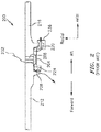
FIG. 2 , a portion of anengine 200 in accordance with the prior art is shown. Theengine 200 incorporates acurvic seal 204 that is used to maintain pressure or temperature as described above. Acurvic joint 208, which includes curvic teeth, mates/interfaces to acompressor disk 212 of the compressor and aturbine disk 216 of the turbine. Theseal 204/joint 208 may provide a centering-feature and transfer of torque as long as a preload in an amount greater than a threshold is maintained. - The
seal 204 includes asnap 220 near the aft-most end of theseal 204. Thesnap 220 allows theseal 204 to engage theturbine disk 216. In contrast to the use of thesnap 220, towards the forward end of the seal 204 (in proximity to the location of the reference character 224) a loose fit is provided between theseal 204 and thecompressor disk 212. Awire seal 228 is included to counter any leakage 232 (the direction of which is shown inFIG. 2 as flowing from high pressure to low pressure) that might otherwise be experienced due to theloose fit 224. The (axial) proximity of thesnap 220 to thejoint 208 imparts a hoop stress into the curvic teeth. This stress reduces the useable lifetime of theseal 204. - The
engine 200 also includes abalance weight 236. Thebalance weight 236 accounts for any non-idealities in terms of the orientation of the interface between the joint 208 and thecompressor disk 212 or the interface between thejoint 208 and theturbine disk 216. As one skilled in the art would appreciate, the non-idealities may be determined based on the use of one or more reference components and one or more algorithms. The algorithms return a result/value that indicates a location on theturbine disk 216 as to where thebalance weight 236 should be located. The location of thebalance weight 236 is selected so as to be equal in magnitude, but 180 degrees out of phase with, the non-ideality in order to cancel the impact of the non-ideality. While shown inFIG. 2 as attaching to theturbine disk 216, thebalance weight 236 may alternatively be attached to thecompressor disk 212. - The following presents a simplified summary in order to provide a basic understanding of some aspects of the disclosure. The summary is not an extensive overview of the disclosure. It is neither intended to identify key or critical elements of the disclosure nor to delineate the scope of the disclosure. The following summary merely presents some concepts of the disclosure in a simplified form as a prelude to the description below.
- Aspects of the disclosure are directed to a seal comprising a first fitting configured to couple to a first disk, and a curvic joint including curvic teeth, where a first distance between the first fitting and the curvic teeth is equal to or greater than a first thickness of the first disk. In some embodiments, the seal further comprises a second fitting configured to couple to a second disk, where a second distance between the second fitting and the curvic teeth is equal to or greater than a second thickness of the second disk. In some embodiments, the first fitting is a first interference fitting. In some embodiments, the second fitting is a second interference fitting. In some embodiments, the second fitting is a loose fitting. In some embodiments, the seal further comprises a wire seal incorporated as part of the second fitting. In some embodiments, the seal further comprises a balance weight. In some embodiments, the balance weight is substantially located in the same axial plane as the curvic joint. In some embodiments, the seal further comprises an anti-rotation tab configured to couple to a slot of the first disk. In some embodiments, the first distance is less than three times the thickness of the first disk.
- Aspects of the disclosure are directed to an engine comprising a compressor disk, a turbine disk, and a seal including: a first fitting configured to couple to the turbine disk, a second fitting configured to couple to the compressor disk, and a curvic joint including curvic teeth, where a first axial distance between the first fitting and the curvic teeth is greater than or equal to a first radial thickness of the turbine disk. In some embodiments, a second axial distance between the second fitting and the curvic teeth is greater than or equal to a second radial thickness of the compressor disk. In some embodiments, at least one of the first fitting and the second fitting is an interference fitting. In some embodiments, one of the first fitting and the second fitting is an interference fitting and the other of the first fitting and the second fitting is a loose fitting. In some embodiments, the engine further comprises a wire seal incorporated as part of the loose fitting. In some embodiments, the seal includes a balance weight. In some embodiments, the balance weight is substantially located in the same axial plane as the curvic joint. In some embodiments, the seal includes an anti-rotation tab configured to couple to a slot of the turbine disk. In some embodiments, the seal includes an anti-rotation tab configured to couple to a slot of the compressor disk.
- The present disclosure is illustrated by way of example and not limited in the accompanying figures in which like reference numerals indicate similar elements. The drawings are not necessarily drawn to scale unless specifically indicated otherwise.
-
FIG. 1 is a side cutaway illustration of a geared turbine engine. -
FIG. 2 illustrates a portion of a prior art engine incorporating a curvic seal and a balance weight. -
FIG. 3 illustrates a portion of an engine in accordance with aspects of this disclosure. -
FIG. 4 illustrates a plot of stress versus fitting distance in accordance with aspects of this disclosure. -
FIGS. 5A-5B illustrate a tab of a seal coupled to a slot of a disk in accordance with aspects of this disclosure. -
FIG. 6 illustrates a curvic interface between a first disk and a second disk in accordance with aspects of this disclosure. -
FIG. 7 illustrates a seal incorporated as part of a curvic interface in accordance with aspects of this disclosure. - It is noted that various connections are set forth between elements in the following description and in the drawings (the contents of which are included in this disclosure by way of reference). It is noted that these connections are general and, unless specified otherwise, may be direct or indirect and that this specification is not intended to be limiting in this respect. A coupling between two or more entities may refer to a direct connection or an indirect connection. An indirect connection may incorporate one or more intervening entities.
- In accordance with aspects of the disclosure, apparatuses, systems, and methods are directed to a curvic seal. The seal may be incorporated as part of one or more sections of an engine. The seal may include one or more snaps for coupling the seal to a compressor disk or a turbine disk. A location of a snap may be related to a dimension of the compressor disk or a dimension of the turbine disk. In some embodiments, a balance weight/flange may be incorporated in proximity to a curvic joint. In some embodiments, the seal may include a tab that mates with a slot in the compressor disk and/or a slot in the turbine disk to provide anti-rotation.
- Aspects of the disclosure may be applied in connection with a gas turbine engine.
FIG. 1 is a side cutaway illustration of a gearedturbine engine 10. Thisturbine engine 10 extends along anaxial centerline 12 between anupstream airflow inlet 14 and adownstream airflow exhaust 16. Theturbine engine 10 includes afan section 18, acompressor section 19, acombustor section 20 and aturbine section 21. Thecompressor section 19 includes a low pressure compressor (LPC)section 19A and a high pressure compressor (HPC)section 19B. Theturbine section 21 includes a high pressure turbine (HPT)section 21A and a low pressure turbine (LPT)section 21B. - The engine sections 18-21 are arranged sequentially along the
centerline 12 within anengine housing 22. Each of the engine sections 18-19B, 21A and 21B includes a respective rotor 24-28. Each of these rotors 24-28 includes a plurality of rotor blades arranged circumferentially around and connected to one or more respective rotor disks. The rotor blades, for example, may be formed integral with or mechanically fastened, welded, brazed, adhered and/or otherwise attached to the respective rotor disk(s). - The
fan rotor 24 is connected to agear train 30, for example, through afan shaft 32. Thegear train 30 and theLPC rotor 25 are connected to and driven by theLPT rotor 28 through alow speed shaft 33. TheHPC rotor 26 is connected to and driven by theHPT rotor 27 through ahigh speed shaft 34. The shafts 32-34 are rotatably supported by a plurality ofbearings 36; e.g., rolling element and/or thrust bearings. Each of thesebearings 36 is connected to theengine housing 22 by at least one stationary structure such as, for example, an annular support strut. - During operation, air enters the
turbine engine 10 through theairflow inlet 14, and is directed through thefan section 18 and into acore gas path 38 and abypass gas path 40. The air within thecore gas path 38 may be referred to as "core air". The air within thebypass gas path 40 may be referred to as "bypass air". The core air is directed through the engine sections 19-21, and exits theturbine engine 10 through theairflow exhaust 16 to provide forward engine thrust. Within thecombustor section 20, fuel is injected into acombustion chamber 42 and mixed with compressed core air. This fuel-core air mixture is ignited to power theturbine engine 10. The bypass air is directed through thebypass gas path 40 and out of theturbine engine 10 through abypass nozzle 44 to provide additional forward engine thrust. This additional forward engine thrust may account for a majority (e.g., more than 70 percent) of total engine thrust. Alternatively, at least some of the bypass air may be directed out of theturbine engine 10 through a thrust reverser to provide reverse engine thrust. -
FIG. 1 represents one possible configuration for anengine 10. Aspects of the disclosure may be applied in connection with other environments, including additional configurations for gas turbine engines. Aspects of the disclosure may be applied in connection with non-geared engines. - Referring to
FIG. 3 , a portion of anengine 300 is shown. Theengine 300 may include acurvic seal 304 and a curvic joint 308 (which may include curvic teeth). The curvic joint 308 may interface to acompressor disk 312 and aturbine disk 316. Theseal 304 may include a fitting 320 that may couple theseal 304 to theturbine disk 316. Theseal 304 may include a fitting 324 that may couple theseal 304 to thecompressor disk 312. - One or both of the
fittings fittings FIG. 2 . - As shown in
FIG. 3 , thecompressor disk 312 may have a thickness (e.g., a radial thickness) 312a. Theturbine disk 316 may have a thickness (e.g., a radial thickness) 316a. The fitting 320 may be located a distance (e.g., an axial distance) 320a from the curvic joint/teeth 308. The fitting 324 may be located a distance (e.g., an axial distance) 324a from the curvic joint/teeth 308. - The
distances thicknesses FIG. 4 , aplot 400 is depicted of stress (shown on the vertical axis) imposed on the teeth of the curvic joint 308 from aninterference fit 320 versus distance (e.g.,distance - As part of the
plot 400, various values of the distance are depicted and expressed as a multiple of a "shell thickness"/"disk thickness" (e.g.,thickness - As reflected in
FIG. 4 , as the distance increases the stress imposed decreases. Moreover, due to the (exponential) profile/shape of thecurve 404 associated with theplot 400, the rate at which the stress is reduced may decrease with each incremental unit (e.g., each incremental multiple of shell thickness) of distance that is used. In this respect, a trade-off may be made in a given application environment between the stress that the seal experiences and the overall distance/space that the seal consumes. It has been determined that an approximate distance of at least one shell thickness is desirable in most application environments. But for a few rare instances, it might not be worth using a distance greater than three shell thicknesses as the reduction in stress that is obtained is likely not worth the extra space that the seal consumes. In this respect, the distance may be provisioned to have a value within a range of one and three shell thicknesses in some embodiments. - Due to the
distances fittings flange 336 may be substantially located in the same axial station/plane 340 as the curvic joint 308. As shown inFIG. 3 , thebalance weight 336 may be located on theseal 304. - Referring to
FIG. 5A , theseal 304 may include one or more tabs (e.g., atab 504a) that may be coupled to (e.g., seated within) one or more counterpart slots (e.g., slot 512) formed in thecompressor disk 312. Together, thetab 504a and theslot 512 may provide an anti-rotation feature with respect to theseal 304. Referring toFIG. 5B , in some embodiments one or more slots (e.g., a slot 516) may be formed in theturbine disk 316 to provide for anti-rotation via a coupling of one or more counterpart tabs (e.g.,tab 504b) of theseal 304 and theslot 516. - Referring to
FIG. 6 , a curvic interface between thecompressor disk 312 and theturbine disk 316 is shown. For example,teeth 612 of thecompressor disk 312 are shown as engagingteeth 616 of theturbine disk 316. InFIG. 7 , theseal 304 is shown in proximity/relationship to theteeth 616. - Technical effects and benefits of this disclosure include a seal that has an enhanced lifetime relative to a conventional seal, where the useable lifetime of the seal is based on the stress that is imposed on the seal. A reduction in stress may be obtained by extending a distance between a curvic joint/teeth and a fitting of the seal, the fitting coupling the seal and a disk. In some embodiments, the location of a balance weight in the same axial plane as a curvic joint may provide an enhanced ability to correct imbalance at the curvic joint.
- Aspects of the disclosure have been described in terms of illustrative embodiments thereof. Numerous other embodiments, modifications, and variations within the scope of the appended claims will occur to persons of ordinary skill in the art from a review of this disclosure. For example, one of ordinary skill in the art will appreciate that the steps described in conjunction with the illustrative figures may be performed in other than the recited order, and that one or more steps illustrated may be optional in accordance with aspects of the disclosure. One or more features described in connection with a first embodiment may be combined with one or more features of one or more additional embodiments.
Claims (14)
- A seal (304) comprising:a first fitting (320) configured to couple to a first disk (316); anda curvic joint (308) including curvic teeth,wherein a first distance (320a) between the first fitting (320) and the curvic teeth is equal to or greater than a first thickness (316a) of the first disk (316).
- The seal (304) of claim 1, further comprising:a second fitting (324) configured to couple to a second disk (312),wherein a second distance (324a) between the second fitting (324) and the curvic teeth is equal to or greater than a second thickness (312a) of the second disk (312).
- The seal (304) of claim 2, wherein the first fitting (320) is a first interference fitting.
- The seal (304) of claim 2 or 3, wherein the second fitting (324) is a second interference fitting.
- The seal (304) of claim 2 or 3, wherein the second fitting (324) is a loose fitting.
- The seal (304) of claim 5, further comprising:a wire seal incorporated as part of the second fitting (324).
- The seal (304) of any preceding claim, further comprising:a balance weight (336).
- The seal (304) of claim 7, wherein the balance weight (336) is substantially located in the same axial plane (340) as the curvic joint (308).
- The seal (304) of any preceding claim, further comprising:an anti-rotation tab (504b) configured to couple to a slot (516) of the first disk (316).
- The seal (304) of any preceding claim, wherein the first distance (320a) is less than three times the first thickness (316a) of the first disk (320).
- An engine (300) comprising:a compressor disk (312);a turbine disk (316); andthe seal (304) of any preceding claim including:a or the second fitting (324) configured to couple to the compressor disk
(312); andwherein the first disk (316) is the turbine disk (316), the first distance (320a) is a first axial distance and the first thickness (316a) is a first radial thickness. - The engine (300) of claim 11, wherein a second axial distance (324a) between the second fitting (324) and the curvic teeth is greater than or equal to a second radial thickness (312a) of the compressor disk (312).
- The engine (300) of claim 11 or 12, wherein one of the first fitting (320) and the second fitting (324) is an interference fitting and the other of the first fitting (320) and the second fitting (324) is a loose fitting.
- The engine (300) of claim 11, 12 or 13, wherein the seal (304) includes an anti-rotation tab (504a) configured to couple to a slot (512) of the compressor disk (312).
Applications Claiming Priority (1)
| Application Number | Priority Date | Filing Date | Title |
|---|---|---|---|
| US15/156,993 US10738639B2 (en) | 2016-05-17 | 2016-05-17 | Curvic seal fitting and balance weight locations |
Publications (2)
| Publication Number | Publication Date |
|---|---|
| EP3246516A1 true EP3246516A1 (en) | 2017-11-22 |
| EP3246516B1 EP3246516B1 (en) | 2020-01-08 |
Family
ID=58715076
Family Applications (1)
| Application Number | Title | Priority Date | Filing Date |
|---|---|---|---|
| EP17171600.4A Active EP3246516B1 (en) | 2016-05-17 | 2017-05-17 | Curvic seal fitting and balance weight locations |
Country Status (2)
| Country | Link |
|---|---|
| US (1) | US10738639B2 (en) |
| EP (1) | EP3246516B1 (en) |
Families Citing this family (2)
| Publication number | Priority date | Publication date | Assignee | Title |
|---|---|---|---|---|
| US10316665B2 (en) * | 2013-03-11 | 2019-06-11 | United Technologies Corporation | Full ring curvic seal |
| US11365630B1 (en) * | 2020-12-28 | 2022-06-21 | Rolls-Royce North American Technologies Inc. | Fan rotor with tapered drive joint |
Citations (4)
| Publication number | Priority date | Publication date | Assignee | Title |
|---|---|---|---|---|
| DE2556381A1 (en) * | 1975-10-01 | 1977-04-14 | Gen Connector Corp | PIPE CONNECTION FROM A SOCKET AND A CONNECTING PIPE |
| EP2687678A1 (en) * | 2012-07-18 | 2014-01-22 | Siemens Aktiengesellschaft | A rotor for a radial compressor and a method for construction thereof |
| WO2014197024A2 (en) * | 2013-03-11 | 2014-12-11 | United Technologies Corporation | Full ring curvic seal |
| WO2014197074A2 (en) * | 2013-03-14 | 2014-12-11 | United Technologies Corporation | Curvic seal for gas turbine enigne |
Family Cites Families (14)
| Publication number | Priority date | Publication date | Assignee | Title |
|---|---|---|---|---|
| US3356339A (en) | 1966-12-12 | 1967-12-05 | Gen Motors Corp | Turbine rotor |
| US3814539A (en) | 1972-10-04 | 1974-06-04 | Gen Electric | Rotor sealing arrangement for an axial flow fluid turbine |
| US5537814A (en) | 1994-09-28 | 1996-07-23 | General Electric Company | High pressure gas generator rotor tie rod system for gas turbine engine |
| US6250883B1 (en) | 1999-04-13 | 2001-06-26 | Alliedsignal Inc. | Integral ceramic blisk assembly |
| US6364634B1 (en) | 2000-09-29 | 2002-04-02 | General Motors Corporation | Turbocharger rotor with alignment couplings |
| US6568692B2 (en) | 2001-03-02 | 2003-05-27 | Honeywell International, Inc. | Low stress seal |
| DE10312056B3 (en) * | 2003-03-18 | 2004-11-18 | Spicer Gelenkwellenbau Gmbh & Co. Kg | Balancing agent for a cardan shaft |
| US7448221B2 (en) | 2004-12-17 | 2008-11-11 | United Technologies Corporation | Turbine engine rotor stack |
| US7309210B2 (en) | 2004-12-17 | 2007-12-18 | United Technologies Corporation | Turbine engine rotor stack |
| US8215919B2 (en) | 2008-02-22 | 2012-07-10 | Hamilton Sundstrand Corporation | Curved tooth coupling for a miniature gas turbine engine |
| US8727702B2 (en) * | 2008-05-30 | 2014-05-20 | United Technologies Corporation | Hoop snap spacer |
| US8616854B2 (en) * | 2009-03-05 | 2013-12-31 | Rolls-Royce Corporation | Nose cone assembly |
| US20140064946A1 (en) | 2012-09-06 | 2014-03-06 | Solar Turbines Incorporated | Gas turbine engine compressor undercut spacer |
| US9303521B2 (en) * | 2012-09-27 | 2016-04-05 | United Technologies Corporation | Interstage coverplate assembly for arranging between adjacent rotor stages of a rotor assembly |
-
2016
- 2016-05-17 US US15/156,993 patent/US10738639B2/en active Active
-
2017
- 2017-05-17 EP EP17171600.4A patent/EP3246516B1/en active Active
Patent Citations (4)
| Publication number | Priority date | Publication date | Assignee | Title |
|---|---|---|---|---|
| DE2556381A1 (en) * | 1975-10-01 | 1977-04-14 | Gen Connector Corp | PIPE CONNECTION FROM A SOCKET AND A CONNECTING PIPE |
| EP2687678A1 (en) * | 2012-07-18 | 2014-01-22 | Siemens Aktiengesellschaft | A rotor for a radial compressor and a method for construction thereof |
| WO2014197024A2 (en) * | 2013-03-11 | 2014-12-11 | United Technologies Corporation | Full ring curvic seal |
| WO2014197074A2 (en) * | 2013-03-14 | 2014-12-11 | United Technologies Corporation | Curvic seal for gas turbine enigne |
Also Published As
| Publication number | Publication date |
|---|---|
| US20170335702A1 (en) | 2017-11-23 |
| EP3246516B1 (en) | 2020-01-08 |
| US10738639B2 (en) | 2020-08-11 |
Similar Documents
| Publication | Publication Date | Title |
|---|---|---|
| US10718270B2 (en) | Hydrostatic non-contact seal with dual material | |
| US10641180B2 (en) | Hydrostatic non-contact seal with varied thickness beams | |
| US20160312695A1 (en) | Turboprop engine with compressor turbine shroud | |
| EP3418610B1 (en) | Hydrostatic non-contact seal with weight reduction pocket | |
| EP3290755A1 (en) | Floating, non-contact seal with at least three beams | |
| US10690060B2 (en) | Triple bend finger seal and deflection thereof | |
| CN107023326A (en) | For the manifold and manufacture method used in clearance control system | |
| US8734089B2 (en) | Damper seal and vane assembly for a gas turbine engine | |
| EP3246516B1 (en) | Curvic seal fitting and balance weight locations | |
| EP3181945B1 (en) | Damper seal installation features | |
| EP3404214B1 (en) | Blade outer air seal assembly and gas turbine engine with such an assembly | |
| EP3312394B1 (en) | Engine cases and associated flange | |
| EP3081748B1 (en) | Gas turbine engine system comprising a seal ring | |
| EP3284917B1 (en) | Active clearance control collector to manifold insert | |
| EP3244021B1 (en) | Engine comprising a seal | |
| EP3851634A1 (en) | Seal element for sealing a joint between a rotor blade and a rotor disk of a turbine engine | |
| EP3309364B1 (en) | System of an engine | |
| US10036503B2 (en) | Shim to maintain gap during engine assembly | |
| WO2014204629A1 (en) | Windback heat shield | |
| WO2014052949A1 (en) | Combustor seal system for a gas turbine engine |
Legal Events
| Date | Code | Title | Description |
|---|---|---|---|
| PUAI | Public reference made under article 153(3) epc to a published international application that has entered the european phase |
Free format text: ORIGINAL CODE: 0009012 |
|
| STAA | Information on the status of an ep patent application or granted ep patent |
Free format text: STATUS: THE APPLICATION HAS BEEN PUBLISHED |
|
| AK | Designated contracting states |
Kind code of ref document: A1 Designated state(s): AL AT BE BG CH CY CZ DE DK EE ES FI FR GB GR HR HU IE IS IT LI LT LU LV MC MK MT NL NO PL PT RO RS SE SI SK SM TR |
|
| AX | Request for extension of the european patent |
Extension state: BA ME |
|
| STAA | Information on the status of an ep patent application or granted ep patent |
Free format text: STATUS: REQUEST FOR EXAMINATION WAS MADE |
|
| 17P | Request for examination filed |
Effective date: 20180521 |
|
| RBV | Designated contracting states (corrected) |
Designated state(s): AL AT BE BG CH CY CZ DE DK EE ES FI FR GB GR HR HU IE IS IT LI LT LU LV MC MK MT NL NO PL PT RO RS SE SI SK SM TR |
|
| STAA | Information on the status of an ep patent application or granted ep patent |
Free format text: STATUS: EXAMINATION IS IN PROGRESS |
|
| 17Q | First examination report despatched |
Effective date: 20190108 |
|
| GRAP | Despatch of communication of intention to grant a patent |
Free format text: ORIGINAL CODE: EPIDOSNIGR1 |
|
| STAA | Information on the status of an ep patent application or granted ep patent |
Free format text: STATUS: GRANT OF PATENT IS INTENDED |
|
| INTG | Intention to grant announced |
Effective date: 20190725 |
|
| GRAS | Grant fee paid |
Free format text: ORIGINAL CODE: EPIDOSNIGR3 |
|
| GRAA | (expected) grant |
Free format text: ORIGINAL CODE: 0009210 |
|
| STAA | Information on the status of an ep patent application or granted ep patent |
Free format text: STATUS: THE PATENT HAS BEEN GRANTED |
|
| AK | Designated contracting states |
Kind code of ref document: B1 Designated state(s): AL AT BE BG CH CY CZ DE DK EE ES FI FR GB GR HR HU IE IS IT LI LT LU LV MC MK MT NL NO PL PT RO RS SE SI SK SM TR |
|
| REG | Reference to a national code |
Ref country code: GB Ref legal event code: FG4D |
|
| REG | Reference to a national code |
Ref country code: CH Ref legal event code: EP |
|
| REG | Reference to a national code |
Ref country code: DE Ref legal event code: R096 Ref document number: 602017010547 Country of ref document: DE |
|
| REG | Reference to a national code |
Ref country code: IE Ref legal event code: FG4D |
|
| REG | Reference to a national code |
Ref country code: AT Ref legal event code: REF Ref document number: 1222954 Country of ref document: AT Kind code of ref document: T Effective date: 20200215 |
|
| REG | Reference to a national code |
Ref country code: NL Ref legal event code: MP Effective date: 20200108 |
|
| REG | Reference to a national code |
Ref country code: LT Ref legal event code: MG4D |
|
| PG25 | Lapsed in a contracting state [announced via postgrant information from national office to epo] |
Ref country code: FI Free format text: LAPSE BECAUSE OF FAILURE TO SUBMIT A TRANSLATION OF THE DESCRIPTION OR TO PAY THE FEE WITHIN THE PRESCRIBED TIME-LIMIT Effective date: 20200108 Ref country code: LT Free format text: LAPSE BECAUSE OF FAILURE TO SUBMIT A TRANSLATION OF THE DESCRIPTION OR TO PAY THE FEE WITHIN THE PRESCRIBED TIME-LIMIT Effective date: 20200108 Ref country code: RS Free format text: LAPSE BECAUSE OF FAILURE TO SUBMIT A TRANSLATION OF THE DESCRIPTION OR TO PAY THE FEE WITHIN THE PRESCRIBED TIME-LIMIT Effective date: 20200108 Ref country code: NO Free format text: LAPSE BECAUSE OF FAILURE TO SUBMIT A TRANSLATION OF THE DESCRIPTION OR TO PAY THE FEE WITHIN THE PRESCRIBED TIME-LIMIT Effective date: 20200408 Ref country code: PT Free format text: LAPSE BECAUSE OF FAILURE TO SUBMIT A TRANSLATION OF THE DESCRIPTION OR TO PAY THE FEE WITHIN THE PRESCRIBED TIME-LIMIT Effective date: 20200531 Ref country code: NL Free format text: LAPSE BECAUSE OF FAILURE TO SUBMIT A TRANSLATION OF THE DESCRIPTION OR TO PAY THE FEE WITHIN THE PRESCRIBED TIME-LIMIT Effective date: 20200108 |
|
| PG25 | Lapsed in a contracting state [announced via postgrant information from national office to epo] |
Ref country code: HR Free format text: LAPSE BECAUSE OF FAILURE TO SUBMIT A TRANSLATION OF THE DESCRIPTION OR TO PAY THE FEE WITHIN THE PRESCRIBED TIME-LIMIT Effective date: 20200108 Ref country code: BG Free format text: LAPSE BECAUSE OF FAILURE TO SUBMIT A TRANSLATION OF THE DESCRIPTION OR TO PAY THE FEE WITHIN THE PRESCRIBED TIME-LIMIT Effective date: 20200408 Ref country code: GR Free format text: LAPSE BECAUSE OF FAILURE TO SUBMIT A TRANSLATION OF THE DESCRIPTION OR TO PAY THE FEE WITHIN THE PRESCRIBED TIME-LIMIT Effective date: 20200409 Ref country code: LV Free format text: LAPSE BECAUSE OF FAILURE TO SUBMIT A TRANSLATION OF THE DESCRIPTION OR TO PAY THE FEE WITHIN THE PRESCRIBED TIME-LIMIT Effective date: 20200108 Ref country code: IS Free format text: LAPSE BECAUSE OF FAILURE TO SUBMIT A TRANSLATION OF THE DESCRIPTION OR TO PAY THE FEE WITHIN THE PRESCRIBED TIME-LIMIT Effective date: 20200508 Ref country code: SE Free format text: LAPSE BECAUSE OF FAILURE TO SUBMIT A TRANSLATION OF THE DESCRIPTION OR TO PAY THE FEE WITHIN THE PRESCRIBED TIME-LIMIT Effective date: 20200108 |
|
| REG | Reference to a national code |
Ref country code: DE Ref legal event code: R097 Ref document number: 602017010547 Country of ref document: DE |
|
| PG25 | Lapsed in a contracting state [announced via postgrant information from national office to epo] |
Ref country code: RO Free format text: LAPSE BECAUSE OF FAILURE TO SUBMIT A TRANSLATION OF THE DESCRIPTION OR TO PAY THE FEE WITHIN THE PRESCRIBED TIME-LIMIT Effective date: 20200108 Ref country code: SK Free format text: LAPSE BECAUSE OF FAILURE TO SUBMIT A TRANSLATION OF THE DESCRIPTION OR TO PAY THE FEE WITHIN THE PRESCRIBED TIME-LIMIT Effective date: 20200108 Ref country code: CZ Free format text: LAPSE BECAUSE OF FAILURE TO SUBMIT A TRANSLATION OF THE DESCRIPTION OR TO PAY THE FEE WITHIN THE PRESCRIBED TIME-LIMIT Effective date: 20200108 Ref country code: ES Free format text: LAPSE BECAUSE OF FAILURE TO SUBMIT A TRANSLATION OF THE DESCRIPTION OR TO PAY THE FEE WITHIN THE PRESCRIBED TIME-LIMIT Effective date: 20200108 Ref country code: DK Free format text: LAPSE BECAUSE OF FAILURE TO SUBMIT A TRANSLATION OF THE DESCRIPTION OR TO PAY THE FEE WITHIN THE PRESCRIBED TIME-LIMIT Effective date: 20200108 Ref country code: SM Free format text: LAPSE BECAUSE OF FAILURE TO SUBMIT A TRANSLATION OF THE DESCRIPTION OR TO PAY THE FEE WITHIN THE PRESCRIBED TIME-LIMIT Effective date: 20200108 Ref country code: EE Free format text: LAPSE BECAUSE OF FAILURE TO SUBMIT A TRANSLATION OF THE DESCRIPTION OR TO PAY THE FEE WITHIN THE PRESCRIBED TIME-LIMIT Effective date: 20200108 |
|
| PLBE | No opposition filed within time limit |
Free format text: ORIGINAL CODE: 0009261 |
|
| STAA | Information on the status of an ep patent application or granted ep patent |
Free format text: STATUS: NO OPPOSITION FILED WITHIN TIME LIMIT |
|
| REG | Reference to a national code |
Ref country code: AT Ref legal event code: MK05 Ref document number: 1222954 Country of ref document: AT Kind code of ref document: T Effective date: 20200108 |
|
| 26N | No opposition filed |
Effective date: 20201009 |
|
| PG25 | Lapsed in a contracting state [announced via postgrant information from national office to epo] |
Ref country code: LI Free format text: LAPSE BECAUSE OF NON-PAYMENT OF DUE FEES Effective date: 20200531 Ref country code: MC Free format text: LAPSE BECAUSE OF FAILURE TO SUBMIT A TRANSLATION OF THE DESCRIPTION OR TO PAY THE FEE WITHIN THE PRESCRIBED TIME-LIMIT Effective date: 20200108 Ref country code: CH Free format text: LAPSE BECAUSE OF NON-PAYMENT OF DUE FEES Effective date: 20200531 Ref country code: IT Free format text: LAPSE BECAUSE OF FAILURE TO SUBMIT A TRANSLATION OF THE DESCRIPTION OR TO PAY THE FEE WITHIN THE PRESCRIBED TIME-LIMIT Effective date: 20200108 Ref country code: AT Free format text: LAPSE BECAUSE OF FAILURE TO SUBMIT A TRANSLATION OF THE DESCRIPTION OR TO PAY THE FEE WITHIN THE PRESCRIBED TIME-LIMIT Effective date: 20200108 |
|
| PG25 | Lapsed in a contracting state [announced via postgrant information from national office to epo] |
Ref country code: PL Free format text: LAPSE BECAUSE OF FAILURE TO SUBMIT A TRANSLATION OF THE DESCRIPTION OR TO PAY THE FEE WITHIN THE PRESCRIBED TIME-LIMIT Effective date: 20200108 Ref country code: SI Free format text: LAPSE BECAUSE OF FAILURE TO SUBMIT A TRANSLATION OF THE DESCRIPTION OR TO PAY THE FEE WITHIN THE PRESCRIBED TIME-LIMIT Effective date: 20200108 |
|
| REG | Reference to a national code |
Ref country code: BE Ref legal event code: MM Effective date: 20200531 |
|
| PG25 | Lapsed in a contracting state [announced via postgrant information from national office to epo] |
Ref country code: LU Free format text: LAPSE BECAUSE OF NON-PAYMENT OF DUE FEES Effective date: 20200517 |
|
| PG25 | Lapsed in a contracting state [announced via postgrant information from national office to epo] |
Ref country code: IE Free format text: LAPSE BECAUSE OF NON-PAYMENT OF DUE FEES Effective date: 20200517 |
|
| PG25 | Lapsed in a contracting state [announced via postgrant information from national office to epo] |
Ref country code: BE Free format text: LAPSE BECAUSE OF NON-PAYMENT OF DUE FEES Effective date: 20200531 |
|
| PG25 | Lapsed in a contracting state [announced via postgrant information from national office to epo] |
Ref country code: TR Free format text: LAPSE BECAUSE OF FAILURE TO SUBMIT A TRANSLATION OF THE DESCRIPTION OR TO PAY THE FEE WITHIN THE PRESCRIBED TIME-LIMIT Effective date: 20200108 Ref country code: MT Free format text: LAPSE BECAUSE OF FAILURE TO SUBMIT A TRANSLATION OF THE DESCRIPTION OR TO PAY THE FEE WITHIN THE PRESCRIBED TIME-LIMIT Effective date: 20200108 Ref country code: CY Free format text: LAPSE BECAUSE OF FAILURE TO SUBMIT A TRANSLATION OF THE DESCRIPTION OR TO PAY THE FEE WITHIN THE PRESCRIBED TIME-LIMIT Effective date: 20200108 |
|
| PG25 | Lapsed in a contracting state [announced via postgrant information from national office to epo] |
Ref country code: MK Free format text: LAPSE BECAUSE OF FAILURE TO SUBMIT A TRANSLATION OF THE DESCRIPTION OR TO PAY THE FEE WITHIN THE PRESCRIBED TIME-LIMIT Effective date: 20200108 Ref country code: AL Free format text: LAPSE BECAUSE OF FAILURE TO SUBMIT A TRANSLATION OF THE DESCRIPTION OR TO PAY THE FEE WITHIN THE PRESCRIBED TIME-LIMIT Effective date: 20200108 |
|
| REG | Reference to a national code |
Ref country code: DE Ref legal event code: R081 Ref document number: 602017010547 Country of ref document: DE Owner name: RAYTHEON TECHNOLOGIES CORPORATION (N.D.GES.D.S, US Free format text: FORMER OWNER: UNITED TECHNOLOGIES CORPORATION, FARMINGTON, CONN., US |
|
| P01 | Opt-out of the competence of the unified patent court (upc) registered |
Effective date: 20230520 |
|
| PGFP | Annual fee paid to national office [announced via postgrant information from national office to epo] |
Ref country code: FR Payment date: 20230420 Year of fee payment: 7 Ref country code: DE Payment date: 20230419 Year of fee payment: 7 |
|
| PGFP | Annual fee paid to national office [announced via postgrant information from national office to epo] |
Ref country code: GB Payment date: 20230420 Year of fee payment: 7 |