EP3246515B1 - Optimierte gezahnte komponente für ein gasturbinentriebwerk - Google Patents
Optimierte gezahnte komponente für ein gasturbinentriebwerk Download PDFInfo
- Publication number
- EP3246515B1 EP3246515B1 EP17171142.7A EP17171142A EP3246515B1 EP 3246515 B1 EP3246515 B1 EP 3246515B1 EP 17171142 A EP17171142 A EP 17171142A EP 3246515 B1 EP3246515 B1 EP 3246515B1
- Authority
- EP
- European Patent Office
- Prior art keywords
- tooth
- stress relief
- bottom land
- feature
- component
- Prior art date
- Legal status (The legal status is an assumption and is not a legal conclusion. Google has not performed a legal analysis and makes no representation as to the accuracy of the status listed.)
- Active
Links
Images


Classifications
-
- F—MECHANICAL ENGINEERING; LIGHTING; HEATING; WEAPONS; BLASTING
- F01—MACHINES OR ENGINES IN GENERAL; ENGINE PLANTS IN GENERAL; STEAM ENGINES
- F01D—NON-POSITIVE DISPLACEMENT MACHINES OR ENGINES, e.g. STEAM TURBINES
- F01D5/00—Blades; Blade-carrying members; Heating, heat-insulating, cooling or antivibration means on the blades or the members
- F01D5/02—Blade-carrying members, e.g. rotors
- F01D5/025—Fixing blade carrying members on shafts
-
- F—MECHANICAL ENGINEERING; LIGHTING; HEATING; WEAPONS; BLASTING
- F01—MACHINES OR ENGINES IN GENERAL; ENGINE PLANTS IN GENERAL; STEAM ENGINES
- F01D—NON-POSITIVE DISPLACEMENT MACHINES OR ENGINES, e.g. STEAM TURBINES
- F01D5/00—Blades; Blade-carrying members; Heating, heat-insulating, cooling or antivibration means on the blades or the members
- F01D5/02—Blade-carrying members, e.g. rotors
- F01D5/026—Shaft to shaft connections
-
- F—MECHANICAL ENGINEERING; LIGHTING; HEATING; WEAPONS; BLASTING
- F01—MACHINES OR ENGINES IN GENERAL; ENGINE PLANTS IN GENERAL; STEAM ENGINES
- F01D—NON-POSITIVE DISPLACEMENT MACHINES OR ENGINES, e.g. STEAM TURBINES
- F01D5/00—Blades; Blade-carrying members; Heating, heat-insulating, cooling or antivibration means on the blades or the members
- F01D5/02—Blade-carrying members, e.g. rotors
- F01D5/06—Rotors for more than one axial stage, e.g. of drum or multiple disc type; Details thereof, e.g. shafts, shaft connections
- F01D5/066—Connecting means for joining rotor-discs or rotor-elements together, e.g. by a central bolt, by clamps
-
- F—MECHANICAL ENGINEERING; LIGHTING; HEATING; WEAPONS; BLASTING
- F01—MACHINES OR ENGINES IN GENERAL; ENGINE PLANTS IN GENERAL; STEAM ENGINES
- F01D—NON-POSITIVE DISPLACEMENT MACHINES OR ENGINES, e.g. STEAM TURBINES
- F01D5/00—Blades; Blade-carrying members; Heating, heat-insulating, cooling or antivibration means on the blades or the members
- F01D5/12—Blades
- F01D5/14—Form or construction
-
- F—MECHANICAL ENGINEERING; LIGHTING; HEATING; WEAPONS; BLASTING
- F01—MACHINES OR ENGINES IN GENERAL; ENGINE PLANTS IN GENERAL; STEAM ENGINES
- F01D—NON-POSITIVE DISPLACEMENT MACHINES OR ENGINES, e.g. STEAM TURBINES
- F01D9/00—Stators
- F01D9/02—Nozzles; Nozzle boxes; Stator blades; Guide conduits, e.g. individual nozzles
-
- F—MECHANICAL ENGINEERING; LIGHTING; HEATING; WEAPONS; BLASTING
- F02—COMBUSTION ENGINES; HOT-GAS OR COMBUSTION-PRODUCT ENGINE PLANTS
- F02C—GAS-TURBINE PLANTS; AIR INTAKES FOR JET-PROPULSION PLANTS; CONTROLLING FUEL SUPPLY IN AIR-BREATHING JET-PROPULSION PLANTS
- F02C3/00—Gas-turbine plants characterised by the use of combustion products as the working fluid
- F02C3/04—Gas-turbine plants characterised by the use of combustion products as the working fluid having a turbine driving a compressor
-
- F—MECHANICAL ENGINEERING; LIGHTING; HEATING; WEAPONS; BLASTING
- F02—COMBUSTION ENGINES; HOT-GAS OR COMBUSTION-PRODUCT ENGINE PLANTS
- F02C—GAS-TURBINE PLANTS; AIR INTAKES FOR JET-PROPULSION PLANTS; CONTROLLING FUEL SUPPLY IN AIR-BREATHING JET-PROPULSION PLANTS
- F02C7/00—Features, components parts, details or accessories, not provided for in, or of interest apart form groups F02C1/00 - F02C6/00; Air intakes for jet-propulsion plants
- F02C7/12—Cooling of plants
- F02C7/16—Cooling of plants characterised by cooling medium
- F02C7/18—Cooling of plants characterised by cooling medium the medium being gaseous, e.g. air
-
- F—MECHANICAL ENGINEERING; LIGHTING; HEATING; WEAPONS; BLASTING
- F05—INDEXING SCHEMES RELATING TO ENGINES OR PUMPS IN VARIOUS SUBCLASSES OF CLASSES F01-F04
- F05D—INDEXING SCHEME FOR ASPECTS RELATING TO NON-POSITIVE-DISPLACEMENT MACHINES OR ENGINES, GAS-TURBINES OR JET-PROPULSION PLANTS
- F05D2220/00—Application
- F05D2220/30—Application in turbines
- F05D2220/32—Application in turbines in gas turbines
-
- F—MECHANICAL ENGINEERING; LIGHTING; HEATING; WEAPONS; BLASTING
- F05—INDEXING SCHEMES RELATING TO ENGINES OR PUMPS IN VARIOUS SUBCLASSES OF CLASSES F01-F04
- F05D—INDEXING SCHEME FOR ASPECTS RELATING TO NON-POSITIVE-DISPLACEMENT MACHINES OR ENGINES, GAS-TURBINES OR JET-PROPULSION PLANTS
- F05D2230/00—Manufacture
- F05D2230/10—Manufacture by removing material
-
- F—MECHANICAL ENGINEERING; LIGHTING; HEATING; WEAPONS; BLASTING
- F05—INDEXING SCHEMES RELATING TO ENGINES OR PUMPS IN VARIOUS SUBCLASSES OF CLASSES F01-F04
- F05D—INDEXING SCHEME FOR ASPECTS RELATING TO NON-POSITIVE-DISPLACEMENT MACHINES OR ENGINES, GAS-TURBINES OR JET-PROPULSION PLANTS
- F05D2250/00—Geometry
- F05D2250/10—Two-dimensional
- F05D2250/13—Two-dimensional trapezoidal
-
- F—MECHANICAL ENGINEERING; LIGHTING; HEATING; WEAPONS; BLASTING
- F05—INDEXING SCHEMES RELATING TO ENGINES OR PUMPS IN VARIOUS SUBCLASSES OF CLASSES F01-F04
- F05D—INDEXING SCHEME FOR ASPECTS RELATING TO NON-POSITIVE-DISPLACEMENT MACHINES OR ENGINES, GAS-TURBINES OR JET-PROPULSION PLANTS
- F05D2250/00—Geometry
- F05D2250/10—Two-dimensional
- F05D2250/18—Two-dimensional patterned
- F05D2250/182—Two-dimensional patterned crenellated, notched
-
- F—MECHANICAL ENGINEERING; LIGHTING; HEATING; WEAPONS; BLASTING
- F05—INDEXING SCHEMES RELATING TO ENGINES OR PUMPS IN VARIOUS SUBCLASSES OF CLASSES F01-F04
- F05D—INDEXING SCHEME FOR ASPECTS RELATING TO NON-POSITIVE-DISPLACEMENT MACHINES OR ENGINES, GAS-TURBINES OR JET-PROPULSION PLANTS
- F05D2250/00—Geometry
- F05D2250/10—Two-dimensional
- F05D2250/18—Two-dimensional patterned
- F05D2250/183—Two-dimensional patterned zigzag
-
- F—MECHANICAL ENGINEERING; LIGHTING; HEATING; WEAPONS; BLASTING
- F05—INDEXING SCHEMES RELATING TO ENGINES OR PUMPS IN VARIOUS SUBCLASSES OF CLASSES F01-F04
- F05D—INDEXING SCHEME FOR ASPECTS RELATING TO NON-POSITIVE-DISPLACEMENT MACHINES OR ENGINES, GAS-TURBINES OR JET-PROPULSION PLANTS
- F05D2250/00—Geometry
- F05D2250/10—Two-dimensional
- F05D2250/18—Two-dimensional patterned
- F05D2250/184—Two-dimensional patterned sinusoidal
-
- F—MECHANICAL ENGINEERING; LIGHTING; HEATING; WEAPONS; BLASTING
- F05—INDEXING SCHEMES RELATING TO ENGINES OR PUMPS IN VARIOUS SUBCLASSES OF CLASSES F01-F04
- F05D—INDEXING SCHEME FOR ASPECTS RELATING TO NON-POSITIVE-DISPLACEMENT MACHINES OR ENGINES, GAS-TURBINES OR JET-PROPULSION PLANTS
- F05D2260/00—Function
- F05D2260/30—Retaining components in desired mutual position
- F05D2260/36—Retaining components in desired mutual position by a form fit connection, e.g. by interlocking
-
- F—MECHANICAL ENGINEERING; LIGHTING; HEATING; WEAPONS; BLASTING
- F05—INDEXING SCHEMES RELATING TO ENGINES OR PUMPS IN VARIOUS SUBCLASSES OF CLASSES F01-F04
- F05D—INDEXING SCHEME FOR ASPECTS RELATING TO NON-POSITIVE-DISPLACEMENT MACHINES OR ENGINES, GAS-TURBINES OR JET-PROPULSION PLANTS
- F05D2260/00—Function
- F05D2260/40—Transmission of power
- F05D2260/403—Transmission of power through the shape of the drive components
-
- F—MECHANICAL ENGINEERING; LIGHTING; HEATING; WEAPONS; BLASTING
- F05—INDEXING SCHEMES RELATING TO ENGINES OR PUMPS IN VARIOUS SUBCLASSES OF CLASSES F01-F04
- F05D—INDEXING SCHEME FOR ASPECTS RELATING TO NON-POSITIVE-DISPLACEMENT MACHINES OR ENGINES, GAS-TURBINES OR JET-PROPULSION PLANTS
- F05D2260/00—Function
- F05D2260/50—Kinematic linkage, i.e. transmission of position
-
- Y—GENERAL TAGGING OF NEW TECHNOLOGICAL DEVELOPMENTS; GENERAL TAGGING OF CROSS-SECTIONAL TECHNOLOGIES SPANNING OVER SEVERAL SECTIONS OF THE IPC; TECHNICAL SUBJECTS COVERED BY FORMER USPC CROSS-REFERENCE ART COLLECTIONS [XRACs] AND DIGESTS
- Y10—TECHNICAL SUBJECTS COVERED BY FORMER USPC
- Y10T—TECHNICAL SUBJECTS COVERED BY FORMER US CLASSIFICATION
- Y10T403/00—Joints and connections
- Y10T403/70—Interfitted members
- Y10T403/7026—Longitudinally splined or fluted rod
- Y10T403/7035—Specific angle or shape of rib, key, groove, or shoulder
Definitions
- the subject matter disclosed herein generally relates to gas turbine engines and, more particularly, to optimized toothed components for gas turbine engines.
- Gas turbine engines include a plurality of elements, each subject to various stresses, loads, etc. Due to the operational conditions within the engines, certain components and/or parts may have shorter operational life spans than other components or parts. For example, toothed components, such as curvic couplings, may be subject to various stresses and stress concentrations that can impact the component life. Accordingly, it may be advantageous to provide improved life components for gas turbine engines.
- EP 0 503 964 discloses a fan shaft coupling having gear teeth wherein the tooth profile includes an involute form.
- US 2003/017878 discloses a curvic coupling design for reduced stress and higher service life.
- a method of manufacturing a toothed component for a gas turbine engine according to claim 1 is provided.
- further embodiments of the method may include that the first tooth, the second tooth, and the stress relief feature are formed simultaneously.
- further embodiments of the method may include that forming the stress relief feature comprises forming a first stress relief notch at a first side of the gable area and forming a second stress relief notch at a second side of the gable area.
- further embodiments of the method may include that the location of the first stress relief notch is located in the fillet radius of the first tooth, and the location of the second stress relief notch is located in the fillet radius of the second tooth.
- further embodiments of the method may include that the toothed component is a curvic of a gas turbine engine.
- further embodiments of the method may include that the curvic comprises a plurality of teeth with a plurality of stress relief features located between adjacent teeth of the plurality of teeth.
- a toothed component for a gas turbine engine according to claim 7 is provided.
- further embodiments of the toothed component may include that the stress relief feature comprises a first stress relief notch at a first side of the gable area and a second stress relief notch at a second side of the gable area.
- further embodiments of the toothed component may include that the location of the first stress relief notch is located in the fillet radius of the first tooth, and the location of the second stress relief notch is located in the fillet radius of the second tooth.
- further embodiments of the toothed component may include that the toothed component is a curvic of a gas turbine engine.
- further embodiments of the toothed component may include that the curvic comprises a plurality of teeth with a plurality of stress relief features located between adjacent teeth of the plurality of teeth.
- a gas turbine engine according to claim 12 and claim 13 is provided.
- FIG. 1A schematically illustrates a gas turbine engine 20.
- the exemplary gas turbine engine 20 is a two-spool turbofan engine that generally incorporates a fan section 22, a compressor section 24, a combustor section 26, and a turbine section 28.
- Alternative engines might include an augmenter section (not shown) among other systems for features.
- the fan section 22 drives air along a bypass flow path B, while the compressor section 24 drives air along a core flow path C for compression and communication into the combustor section 26. Hot combustion gases generated in the combustor section 26 are expanded through the turbine section 28.
- a turbofan gas turbine engine in the disclosed non-limiting embodiment, it should be understood that the concepts described herein are not limited to turbofan engines and these teachings could extend to other types of engines, including but not limited to, three-spool engine architectures.
- the gas turbine engine 20 generally includes a low speed spool 30 and a high speed spool 32 mounted for rotation about an engine centerline longitudinal axis A.
- the low speed spool 30 and the high speed spool 32 may be mounted relative to an engine static structure 33 via several bearing systems 31. It should be understood that other bearing systems 31 may alternatively or additionally be provided.
- the low speed spool 30 generally includes an inner shaft 34 that interconnects a fan 36, a low pressure compressor 38 and a low pressure turbine 39.
- the inner shaft 34 can be connected to the fan 36 through a geared architecture 45 to drive the fan 36 at a lower speed than the low speed spool 30.
- the high speed spool 32 includes an outer shaft 35 that interconnects a high pressure compressor 37 and a high pressure turbine 40.
- the inner shaft 34 and the outer shaft 35 are supported at various axial locations by bearing systems 31 positioned within the engine static structure 33.
- a combustor 42 is arranged between the high pressure compressor 37 and the high pressure turbine 40.
- a mid-turbine frame 44 may be arranged generally between the high pressure turbine 40 and the low pressure turbine 39.
- the mid-turbine frame 44 can support one or more bearing systems 31 of the turbine section 28.
- the mid-turbine frame 44 may include one or more airfoils 46 that extend within the core flow path C.
- the inner shaft 34 and the outer shaft 35 are concentric and rotate via the bearing systems 31 about the engine centerline longitudinal axis A, which is co-linear with their longitudinal axes.
- the core airflow is compressed by the low pressure compressor 38 and the high pressure compressor 37, is mixed with fuel and burned in the combustor 42, and is then expanded over the high pressure turbine 40 and the low pressure turbine 39.
- the high pressure turbine 40 and the low pressure turbine 39 rotationally drive the respective high speed spool 32 and the low speed spool 30 in response to the expansion.
- the pressure ratio of the low pressure turbine 39 can be pressure measured prior to the inlet of the low pressure turbine 39 as related to the pressure at the outlet of the low pressure turbine 39 and prior to an exhaust nozzle of the gas turbine engine 20.
- the bypass ratio of the gas turbine engine 20 is greater than about ten (10:1)
- the fan diameter is significantly larger than that of the low pressure compressor 38
- the low pressure turbine 39 has a pressure ratio that is greater than about five (5:1). It should be understood, however, that the above parameters are only examples of one embodiment of a geared architecture engine and that the present disclosure is applicable to other gas turbine engines, including direct drive turbofans.
- TSFC Thrust Specific Fuel Consumption
- Fan Pressure Ratio is the pressure ratio across a blade of the fan section 22 without the use of a Fan Exit Guide Vane system.
- the low Fan Pressure Ratio according to one non-limiting embodiment of the example gas turbine engine 20 is less than 1.45.
- Low Corrected Fan Tip Speed is the actual fan tip speed divided by an industry standard temperature correction of [(Tram ° R)/(518.7° R)] 0.5 , where T represents the ambient temperature in degrees Rankine.
- the Low Corrected Fan Tip Speed according to one non-limiting embodiment of the example gas turbine engine 20 is less than about 1150 fps (351 m/s).
- Each of the compressor section 24 and the turbine section 28 may include alternating rows of rotor assemblies and vane assemblies (shown schematically) that carry airfoils that extend into the core flow path C.
- the rotor assemblies can carry a plurality of rotating blades 25, while each vane assembly can carry a plurality of vanes 27 that extend into the core flow path C.
- the blades 25 of the rotor assemblies create or extract energy (in the form of pressure) from the core airflow that is communicated through the gas turbine engine 20 along the core flow path C.
- the vanes 27 of the vane assemblies direct the core airflow to the blades 25 to either add or extract energy.
- Various components of a gas turbine engine 20 including but not limited to the airfoils of the blades 25 and the vanes 27 of the compressor section 24 and the turbine section 28, may be subjected to repetitive thermal cycling under widely ranging temperatures and pressures.
- the hardware of the turbine section 28 is particularly subjected to relatively extreme operating conditions. Therefore, some components may require internal cooling circuits for cooling the parts during engine operation.
- Example cooling circuits that include features such as airflow bleed ports are discussed below.
- FIG. 1B is a schematic view of a turbine section that may employ various embodiments disclosed herein.
- Turbine 100 includes a plurality of airfoils, including, for example, one or more blades 101 and vanes 102.
- the airfoils 101, 102 may be hollow bodies with internal cavities defining a number of channels or cavities, hereinafter airfoil cavities, formed therein and extending from an inner diameter 106 to an outer diameter 108, or vice-versa.
- the airfoil cavities may be separated by partitions within the airfoils 101, 102 that may extend either from the inner diameter 106 or the outer diameter 108 of the airfoil 101, 102.
- the partitions may extend for a portion of the length of the airfoil 101, 102, but may stop or end prior to forming a complete wall within the airfoil 101, 102.
- each of the airfoil cavities may be fluidly connected and form a fluid path within the respective airfoil 101, 102.
- the blades 101 and the vanes may include platforms 110 located proximal to the inner diameter thereof. Located below the platforms 110 may be airflow ports and/or bleed orifices that enable air to bleed from the internal cavities of the airfoils 101, 102. A root of the airfoil may connected to or be part of the platform 110.
- the platform 110 may be mounted to an attachment 118 of a turbine disk 112.
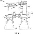
- FIGS. 2A-2B schematic illustrations of a rotor stack mounted to a shaft of a gas turbine engine are shown.
- FIG. 2A shows a side view schematic illustration of a plurality of disks 212a, 212b, 212c mounted to a shaft 220 of a portion of a gas turbine engine 200.
- FIG. 2B shows a detailed, radial view of a coupling of the turbine engine 200 as viewed along the line 2B-2B indicated in FIG. 2A .
- Each disk 212a, 212b, 212c carries or supports an associated set of blades 201a, 201b, 201c by engagement of respective attachments 218.
- a plurality of vanes 202a, 202b, 202c are located along a core flow path C sequentially interspersed with the blades 201a, 201b, 201c.
- the vanes 202a, 202b, 202c comprise airfoils extending radially inward from roots at outboard shrouds/platforms 211 formed as portions of an outer wall 213 of the core flow path C.
- the airfoils of the vanes 202a, 202b, 202c extend inward to inboard platforms 215 forming portions of an inboard wall 217 of the core flow path C.
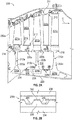
- each of the disks 212a, 212b, 212c has a respective generally annular web 222a, 222b, 222c extending radially outward from a bore 224a, 224b, 224c to the roots 218.
- the bores 224a, 224b, 224c encircle central apertures of the disks 212a, 212b, 212c through which the shaft 220 freely passes with clearance.
- Alternative blades may be unitarily formed with the roots 218 (e.g., as a single piece with continuous microstructure) or non-unitarily integrally formed (e.g., via welding so as to only be destructively removable).
- Outboard spacers 226a, 226b connect adjacent pairs of the disks 212a, 212b, 212c.
- the spacers 226a, 226b are formed separately from the adjacent disks 212a, 212b, 212c.
- the spacers 226a, 226b may each have end portions in contacting engagement with adjacent portions (e.g., roots 218) of the adjacent disks 212a, 212b, 212c.
- Alternative spacers may be integrally formed with (e.g., unitarily formed with or welded to) one of the adjacent disks 212a, 212b, 212c and extend to a contacting engagement with the other disk adjacent disk 212a, 212b, 212c.
- Inter-disk couplings 228a, 228b are provided between the disks 212a, 212b, 212c.
- FIG. 2A shows couplings 228a, 228b radially inboard with respect to associated spacers 226a, 226b.
- the couplings 228a, 228b separate an associated annular inter-disk cavity 230 from an inter-disk cavity 232 between the adjacent bores 224a, 224b, 224c.
- Each coupling 228a, 228b includes a tubular ring-like first structure 234 ( FIGS. 2A-2B ) extending aft from the disk thereahead and a second structure 236 extending forward from the disk aft thereof.
- Each first structure 234 and each second structure 236 are each unitarily-formed with their associated individual disks, extending respectively aft and forward from near the junction of the respective disk webs 222a, 222b, 222c and bores 224a, 224b, 224c.
- the structures 234, 236 may include or be toothed components that are engageable to form the couplings 228a, 228b.
- the structures 234, 236 include interfitting radial splines or teeth 238 in a circumferential array ( FIG. 2B ). That is, in accordance with various embodiments, the structures can be toothed components for a gas turbine engine.
- the teeth 238 have longitudinal spans roughly the same as a radial span and a circumferential span somewhat longer.
- the teeth 238 have distally-tapering side walls 240 extending to ends, apexes, or top lands 242. As shown, the side walls 240 of each tooth 238 contacts the adjacent side walls 240 of the adjacent teeth 238 of the other structure 234, 236.
- each top land 242 there is a gap 244 between each top land 242 and a base or bottom land 246 of the inter-tooth trough of the opposite structure 234, 236.
- the gap 244 enables longitudinal compressive force to reinforce circumferential engagement and maintain the two structures 234, 236 tightly engaged.
- the engagement between the two structures 234, 236 forms the couplings 228a, 228b.
- Snap couplings, curvic couplings, or other spline structures could be used to form the couplings 228a, 228b without departing from the scope of the present disclosure.
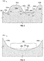
- FIG. 3 a side view illustration of teeth 338a, 338b of a structure 334 of a coupling is schematically shown.
- Each tooth 338a, 338b is defined by respective top lands 342a, 342b, two side walls 340a, 340b, and bottom lands 346a, 346b at the bottom of each side wall 340a, 340b.
- the transition from the side walls 340a, 340b to the bottom lands 346a, 346b is defined by a fillet radius 348.
- Each bottom land 346a, 346b includes a minimum 350 and a maximum 352.
- a minimum line 354 can be drawn from two adjacent minimums 350, with the maximum 352 located between the two adjacent minimums 350, thus defining a gable.
- a maximum line 356 is a line that is parallel to the minimum line 354 and drawn at the maximum 352, as shown in FIG. 3 .
- the incline from the minimum 350 to the maximum 352 of the bottom lands 346a, 346b is referred to as a gable.
- a gable height 358 is defined by a vertical distance between the minimum 350 and the maximum 352, i.e., a distance between the minimum line 354 and the maximum line 356.
- the angle of incline of the bottom lands 346a, 346b (e.g., from the minimum 350 to the maximum 352) is defined by a gable angle 360.
- the features of the bottom land 346a, 346b may be referred to herein as a gable area 362.
- the gable is formed during a manufacturing process of the structures (e.g., structures 234, 236) when forming the teeth.
- the gable is allowed to enable manufacturing mismatch.
- the stress between teeth may be high, and thus reducing the stresses between teeth can provide increased component life.
- various embodiments enable curvic structures (e.g., toothed components) to have reduced stress due to hoop stress.
- an additional grind or processing step is used during the manufacturing of the toothed curvics such that material is removed from the gable area (e.g., gable area 362 of FIG. 3 ).
- material removal enables optimization of a hoop stress concentration factor (KT) of the curvic tooth (e.g., teeth 338a, 338b of FIG. 3 ).
- KT hoop stress concentration factor
- FIG. 4 a structure 434 is shown with different bottom land configurations. Located between a first side wall 440a and a second side wall 440b is a gable area 462.
- a first configuration 464 is shown illustrating an inclined gable similar to that shown in FIG. 3 .
- a second configuration having a first stress relief feature 466 is shown with the inclined portions of the gable area 462 removed (e.g., material is removed from the gable area 462).
- the first stress relief feature 466 represents a removal of material from a traditional gable shape (e.g., as shown in FIG. 3 ).
- the stress relief features, as provided herein, represent a change from a prior bulge formed by the gable to a depression formed in material (although it may be flat).
- a third configuration is shown defining a second stress relief feature 468 with additional material removed from the gable area 462 (as compared to the first stress relief feature 466).
- additional material removed from the gable area 462 (as compared to the first stress relief feature 466).
- FIG. 4 two variations are shown in FIG. 4 , those of skill in the art will appreciate that any amount of material may be removed from the gable area 462 to achieve an improved stress profile at the gable area 462.
- the removal of material in the gable area 462 can range from achieving a "flat" minimum (e.g., the bottom land defines a surface that is level with a minimum line (e.g., line 354 in FIG.
- the stress relief feature can be defined by a plane or flat surface extending from one side wall to another and in other embodiments a curvature from one side wall may be continuous to another side wall. Any curvature ranging between a flat stress relief feature to a full radius stress relief feature are enabled herein.
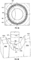
- FIGS. 5A-5B illustrations of a gable area 562 of a structure 534 are shown.
- FIG. 5A illustrates a side view of the gable area 562 indicating the gable material that is removed to form a configuration of an undercut or stress relief feature in accordance with the present disclosure.
- FIG. 5B illustrates an isometric illustration of the shape of the gable area 562 after the gable material is removed.
- a structure 534 includes a first side wall 540a and a second side wall 540b.
- a gable area 562 is defined between the first side wall 540a and the second side wall 540b.
- a gable material 570 represents an amount of material of the structure 534 that is removed to form a stress relief feature 572 in accordance with the present disclosure.
- the removed gable material 570 is not a full radius, and thus a first inflection feature 574a is formed between the stress relief feature 572 and the first side wall 540a and a second inflection feature 574b is formed between the stress relief feature 572 and the second side wall 540b.
- the inflection features 574a, 574b are shown in the isometric illustration of FIG. 5B .
- FIGS. 6A-6B illustrations of a mechanism for forming the stress relief feature of the gable area of a structures, such as a curvic for a gas turbine engine, are shown.
- FIG. 6A shows a configuration for a first pass or cutting of a structure 634 to form half of a gable area 662 between adjacent teeth 638.
- FIG. 6B shows the formation of a stress relief feature 672 in accordance with a non-limiting embodiment of the present disclosure.
- a first cutting tool 676 is used to cut first and second sides of teeth 638 to form gable areas 662 between top lands 642 of teeth of the structure 634.
- the first cutting tool 676 can be used to form two faces in a single pass or cut.
- the first cutting tool 676 can cut two faces of teeth, simultaneously, with the two teeth located at different locations about the structure 634.
- a single pass of the first cutting tool 676 can form bottom lands for two different teeth that are defined by a fillet radius (e.g., as shown in FIG. 3 ).
- a second pass of the first cutting tool 676 can be performed to form the adjacent bottom lands and fillet radius for a single gable area (e.g., to form the structure and configuration shown in FIG. 3 ).
- a second cutting tool 678 is used to remove material from the gable area between adjacent teeth.
- a first tooth 638a is formed by a first pass of the first cutting tool 676 such that the first tooth 638a has a top land 642a, a side wall 640a, and a bottom land 646a.
- a second tooth 638b is formed by a second pass of the first cutting tool 676 such that the second tooth 638b has a top land 642b, a side wall 640b, and a bottom land 646b.
- the second cutting tool 678 is used to make a pass to cut or remove material within the gable area between the first tooth 638a and the second tooth 638b.
- the second cutting tool 678 is configured with a tool width 680 and a tool radius 682.
- the tool width 680 and the tool radius 682 can be selected such that a preselected geometry of a stress relief feature 672 is formed after the cutting operation of the second cutting tool 678.
- the cutting operation of the second cutting tool 678 can form first inflection feature 674a and second inflection feature 674b around the stress relief feature 672, as shown.
- the first cutting tool 676 and the second cutting tool 678 are the same tool configured to make passes to cut the structure multiple times, in different locations relative to the teeth.
- first cutting tool 676 and the second cutting tool 678 are different tools and, further, in some embodiments, the tools may have different geometric configurations, shapes, sizes, etc.
- a single cutting tool can be used to form all of the features of the teeth and/or gable area in a single pass.
- FIG. 7 an alternative configuration in accordance with a non-limiting embodiment of the present disclosure is shown.
- two adjacent teeth 738 are formed with a gable area 762 formed therebetween.
- the maximum 752 is not removed from the gable area 762.
- a second cutting tool 784 is used to cut or form a first stress relief feature 786a and a second stress relief feature 786b.
- Such a configuration will form multiple inflection features within the gable area 762.
- Two inflection features will be formed on either side of each stress relief feature 786a, 786b.
- the configuration shown in FIG. 7 includes five separate inflection features.
- the stress relief features 786a, 786b of FIG. 7 may be referred to as stress relief notches that are cut from the sides of the gable area 762.
- FIG. 8 a flow process to form a structure for a gas turbine engine having stress relief features in accordance with the present disclosure is shown.
- the flow process 800 can be used to form a curvic structure or other toothed structure used in gas turbine engines or other devices, and may be used to form structures and/or configurations as shown and described above.
- the flow process 800 can be performed with one or more cutting tools and further can be used to form tooth structures and/or geometries that are different from those shown and described herein.
- teeth of structure are formed.
- the teeth can be formed by one or more tools, such as cutting and/or grinding tools.
- the teeth can be teeth of a curvic for a gas turbine engine.
- the formation of the teeth can result in a gable area forming between two adjacent teeth (e.g., in the tooth bottom land area).
- the gable area can include a maximum that is reached at a midpoint between the two adjacent teeth (e.g., as shown in FIG. 3 ).
- one or more stress relief features are formed in the gable area between adjacent teeth.
- the one or more stress relief features are formed by the removal of structure material in the gable area, as described above.
- the stress relief features can be achieved by one or more passes of a tool, such as cutting and/or grinding tools.
- the process 800 can be performed using a single tool that is used to form both the teeth and the stress relief features.
- different tools having different sizes, geometries, cutting/grinding surfaces, etc. can be used.
- the forming of the teeth and the stress relief features can be performed in a single operation or may be performed as separate operations.
- a primary stress driver (hoop stress) concentration factor can be reduced by forming a stress relief feature in a gable area of toothed components (e.g., a curvic or other structure in a gas turbine engine).
- stress reductions can be 5% - 35% or greater hoop stress KT reduction.
- the stress reductions can provide significant part life.
- some non-limiting embodiments can double the life of a toothed component.
- turbine disk configurations as described herein may be applied to industrial applications and/or industrial gas turbine engines, land based or otherwise.
Landscapes
- Engineering & Computer Science (AREA)
- Mechanical Engineering (AREA)
- General Engineering & Computer Science (AREA)
- Chemical & Material Sciences (AREA)
- Combustion & Propulsion (AREA)
- Turbine Rotor Nozzle Sealing (AREA)
Claims (13)
- Verfahren zum Herstellen einer gezahnten Komponente für ein Gasturbinentriebwerk (20), wobei das Verfahren Folgendes umfasst:Bilden eines ersten Zahns (238; 338a) in der Komponente, wobei der erste Zahn eine obere Fläche (342a), eine untere Fläche (246, 346a), eine Seitenwand (240, 340a, 440a, 540a, 640a), die sich von der oberen Fläche zur unteren Fläche erstreckt, und einen Rundungsradius (348) umfasst, der einen Übergang zwischen der Seitenwand und der unteren Fläche bildet, wobei die untere Fläche ein Minimum angrenzend an den Rundungsradius und ein Maximum entfernt von dem Rundungsradius aufweist;Bilden eines zweiten Zahns (238, 338b) in der Komponente angrenzend an den ersten Zahn, wobei der zweite Zahn eine obere Fläche (342b), eine untere Fläche (346b), eine Seitenwand (340b, 440b, 540b, 640b), die sich von der oberen Fläche zur unteren Fläche erstreckt und dem ersten Zahn zugewandt ist, und einen Rundungsradius (348) umfasst, der einen Übergang zwischen der Seitenwand und der unteren Fläche bildet, wobei sich die untere Fläche des zweiten Zahns von einem jeweiligen Minimum angrenzend an den jeweiligen Rundungsradius zu dem Maximum der unteren Fläche des ersten Zahns erstreckt, wobei das Maximum der unteren Fläche des ersten Zahns und das Maximum der unteren Fläche des zweiten Zahns einen Giebelbereich (362; 462; 562; 662) der Komponente definieren, der seine Spitze dort erreicht, wo das Maximum der unteren Fläche des ersten Zahns und das Maximum der Unterseite der zweiten Fläche zusammenkommen, wobei der Giebelbereich der Komponente einen primären Spannungstreiberkonzentrationsfaktor aufweist; und gekennzeichnet durchBilden eines Spannungsentlastungsmerkmals (464; 466; 468; 572; 672), nach Bildung des ersten Zahns und des zweiten Zahns, durch Entfernen von Material an der Spitze der zusammengekommenen Maxima im Giebelbereich, so dass das Spannungsentlastungsmerkmal den primären Spannungstreiberkonzentrationsfaktor in dem Giebelbereich während des Betriebs der gezahnten Komponente im Vergleich zum primären Spannungstreiberkonzentrationsfaktor in einem Giebelbereich einer gezahnten Komponente ohne dieses Spannungsentlastungsmerkmal verringert, wobei die Entfernung von Material die Spitze (352) der zusammengekommenen Maxima entfernt und die Bildung von zwei gesonderten Spitzen in der Form eines ersten Wendemerkmals (574a, 674a) und eines zweiten Wendemerkmals (574b, 674b) bewirkt, undwobei das Spannungsentlastungsmerkmal des erste Wendemerkmal (574a, 674a) zwischen dem Spannungsentlastungsmerkmal und der Seitenwand des ersten Zahns und das zweite Wendemerkmal (574b, 674b) zwischen dem Spannungsentlastungsmerkmal und der Seitenwand des zweiten Zahns bildet.
- Verfahren nach Anspruch 1, wobei der erste Zahn, der zweite Zahn und das Spannungsentlastungsmerkmal gleichzeitig gebildet werden.
- Verfahren nach einem der vorstehenden Ansprüche, wobei das Bilden des Spannungsentlastungsmerkmals das Bilden einer ersten Spannungsentlastungskerbe (768a) auf einer ersten Seite des Giebelbereichs und das Bilden einer zweiten Spannungsentlastungskerbe (768b) auf einer zweiten Seite des Giebelbereichs umfasst.
- Verfahren nach Anspruch 3, wobei die Position der ersten Spannungsentlastungskerbe in dem Rundungsradius des ersten Zahns angeordnet ist und die Position der zweiten Spannungsentlastungskerbe in dem Rundungsradius des zweiten Zahns angeordnet ist.
- Verfahren nach einem der vorstehenden Ansprüche, wobei die gezahnte Komponente eine Curvic-Kupplung eines Gasturbinentriebwerks ist.
- Verfahren nach Anspruch 5, wobei die Curvic-Kupplung eine Vielzahl von Zähnen mit einer Vielzahl von Spannungsentlastungsmerkmalen, die zwischen angrenzenden Zähnen aus der Vielzahl von Zähnen angeordnet sind, umfasst.
- Gezahnte Komponente für ein Gasturbinentriebwerk (20), wobei die gezahnte Komponente Folgendes umfasst:eine Struktur (234), die so konfiguriert ist, dass sie in eine andere Komponente des Gasturbinentriebwerks eingreift;einen ersten Zahn (238, 338a) an der Struktur, wobei der erste Zahn eine obere Fläche, eine untere Fläche, eine Seitenwand (240, 340a, 440a, 540a, 640a), die sich von der oberen Fläche zur unteren Fläche erstreckt, einen Rundungsradius umfasst, der einen Übergang zwischen der Seitenwand und der unteren Fläche bildet, wobei die untere Fläche ein Minimum angrenzend an den Rundungsradius und ein Maximum entfernt von dem Rundungsradius aufweist; undeinen zweiten Zahn (238, 338b) an der Struktur angrenzend an den ersten Zahn, wobei der zweite Zahn eine obere Fläche (242, 342b), eine untere Fläche (246, 346b), eine Seitenwand (240, 340b, 440b, 540b, 640b), die sich von der oberen Fläche zur unteren Fläche erstreckt und dem ersten Zahn zugewandt ist, und einen Rundungsradius (348) umfasst, der einen Übergang zwischen der Seitenwand und der unteren Fläche bildet, wobei sich die untere Fläche des zweiten Zahns von einem jeweiligen Minimum angrenzend an den jeweiligen Rundungsradius zu dem Maximum der unteren Fläche des ersten Zahns erstreckt,wobei das Maximum der unteren Fläche des ersten Zahns und das Maximum der unteren Fläche des zweiten Zahns einen Giebelbereich (362; 462; 562; 662) der Komponente definieren, der seine Spitze dort erreicht, wo das Maximum der unteren Fläche des ersten Zahns und das Maximum der unteren Fläche des zweiten Zahns zusammenkommen, wobei der Giebelbereich der Komponente einen primären Spannungstreiberkonzentrationsfaktor aufweist,wobei die gezahnte Komponente dadurch gekennzeichnet ist, dass sie mindestens ein Spannungsentlastungsmerkmal (464; 466; 468; 572; 672) umfasst, das eine Region entfernten Materials umfasst, die in dem Giebelbereich durch Entfernen von Material an der Spitze (352) der zwei Maxima nach Bildung der Spitze (352) gebildet ist, und die Bildung von zwei gesonderten Spitzen in der Form eines ersten Wendemerkmals (574a, 674a) und eines zweiten Wendemerkmals (574b, 674b) bewirkt und eine verringerte Spannungskonzentration des primären Spannungstreiberkonzentrationsfaktors in dem Giebelbereich während des Betriebs der gezahnten Komponente im Vergleich zum primären Spannungstreiberkonzentrationsfaktor in einem Giebelbereich einer gezahnten Komponente ohne dieses Spannungsentlastungsmerkmal definiert;des erste Wendemerkmal (574a, 674a) zwischen dem Spannungsentlastungsmerkmal und der Seitenwand des ersten Zahns; unddas zweite Wendemerkmal (574b, 674b) zwischen dem Spannungsentlastungsmerkmal und der Seitenwand des zweiten Zahns umfasst.
- Gezahnte Komponente nach Anspruch 7, wobei das Spannungsentlastungsmerkmal eine erste Spannungsentlastungskerbe (768a) auf einer ersten Seite des Giebelbereichs und eine zweite Spannungsentlastungskerbe (768b) auf einer zweiten Seite des Giebelbereichs umfasst.
- Gezahnte Komponente nach Anspruch 8, wobei die Position der ersten Spannungsentlastungskerbe in dem Rundungsradius des ersten Zahns angeordnet ist und die Position der zweiten Spannungsentlastungskerbe in dem Rundungsradius des zweiten Zahns angeordnet ist.
- Gezahnte Komponente nach einem der Ansprüche 7-9, wobei die gezahnte Komponente eine Curvic-Kupplung eines Gasturbinentriebwerks ist.
- Gezahnte Komponente nach Anspruch 10, wobei die Curvic-Kupplung eine Vielzahl von Zähnen mit einer Vielzahl von Spannungsentlastungsmerkmalen, die zwischen angrenzenden Zähnen aus der Vielzahl von Zähnen angeordnet sind, umfasst.
- Gasturbinentriebwerk (20), die gezahnte Komponente nach einem der Ansprüche 7-11 beinhaltend.
- Gasturbinentriebwerk nach Anspruch 12, wobei die Struktur, die so konfiguriert ist, dass sie in eine andere Komponente des Gasturbinentriebwerks eingreift, eine erste Struktur ist, wobei das Triebwerk ferner eine zweite Struktur (236) umfasst, die mit der ersten Struktur im Eingriff steht, wobei die zweite Struktur ein zweites Strukturspannungsentlastungsmerkmal aufweist.
Applications Claiming Priority (1)
| Application Number | Priority Date | Filing Date | Title |
|---|---|---|---|
| US15/155,242 US10584590B2 (en) | 2016-05-16 | 2016-05-16 | Toothed component optimization for gas turbine engine |
Publications (2)
| Publication Number | Publication Date |
|---|---|
| EP3246515A1 EP3246515A1 (de) | 2017-11-22 |
| EP3246515B1 true EP3246515B1 (de) | 2021-08-18 |
Family
ID=58709856
Family Applications (1)
| Application Number | Title | Priority Date | Filing Date |
|---|---|---|---|
| EP17171142.7A Active EP3246515B1 (de) | 2016-05-16 | 2017-05-15 | Optimierte gezahnte komponente für ein gasturbinentriebwerk |
Country Status (2)
| Country | Link |
|---|---|
| US (1) | US10584590B2 (de) |
| EP (1) | EP3246515B1 (de) |
Families Citing this family (2)
| Publication number | Priority date | Publication date | Assignee | Title |
|---|---|---|---|---|
| CN109517607A (zh) * | 2018-11-06 | 2019-03-26 | 首钢集团有限公司 | 一种用于分析干熄焦炉牛腿部位应力的方法及系统 |
| DE102019219403A1 (de) | 2019-12-12 | 2021-06-17 | MTU Aero Engines AG | Rotor für eine Strömungsmaschine und Strömungsmaschine |
Citations (1)
| Publication number | Priority date | Publication date | Assignee | Title |
|---|---|---|---|---|
| US20030017878A1 (en) * | 2001-07-13 | 2003-01-23 | Honeywell International, Inc. | Curvic coupling fatigue life enhancement through unique compound root fillet design |
Family Cites Families (17)
| Publication number | Priority date | Publication date | Assignee | Title |
|---|---|---|---|---|
| US2427641A (en) * | 1942-05-22 | 1947-09-16 | Gleason Works | Method of producing clutches |
| US3356339A (en) * | 1966-12-12 | 1967-12-05 | Gen Motors Corp | Turbine rotor |
| US4060007A (en) * | 1976-09-13 | 1977-11-29 | Brown & Sharpe Manufacturing Company | Clutch teeth |
| US4573875A (en) * | 1984-05-29 | 1986-03-04 | General Electric Company | Captured radial key for steam turbine wheels |
| CA2062025A1 (en) | 1991-03-14 | 1992-09-15 | David E. Bulman | Fan shaft spline coupling having increased loading capacity and tooth geometry therefor |
| GB9410989D0 (en) * | 1994-06-01 | 1994-07-20 | Renishaw Plc | Indexing mechanism |
| US5536144A (en) * | 1994-10-13 | 1996-07-16 | General Motors Corporation | Turbocharger turbine wheel and shaft assembly |
| US6164880A (en) * | 1999-02-23 | 2000-12-26 | Caterpillar Inc. | Method for producing and controlling a fillet on a gear |
| US6572337B1 (en) * | 1999-11-30 | 2003-06-03 | General Electric Co. | Turbine rotor torque transmission |
| US7309210B2 (en) | 2004-12-17 | 2007-12-18 | United Technologies Corporation | Turbine engine rotor stack |
| WO2006075363A1 (ja) * | 2005-01-12 | 2006-07-20 | Mitsubishi Materials Pmg Corporation | 内接型ギヤポンプのインナーロータ |
| US20070071545A1 (en) | 2005-08-26 | 2007-03-29 | Honeywell International, Inc. | Lubricated Hirth serration coupling |
| FR2952138B1 (fr) * | 2009-10-30 | 2012-04-20 | Turbomeca | Procede de protection de passage d'air dans un couplage de pieces motrices en environnement non securise, couplage de mise en oeuvre et ligne rotors equipee de tels couplages |
| US8465373B2 (en) * | 2009-12-29 | 2013-06-18 | Rolls-Royce Corporation | Face coupling |
| US9212557B2 (en) * | 2011-08-31 | 2015-12-15 | United Technologies Corporation | Assembly and method preventing tie shaft unwinding |
| EP2650071A1 (de) * | 2012-04-11 | 2013-10-16 | Siemens Aktiengesellschaft | Verfahren und Werkzeug zur Herstellung einer Kupplung mit einer flachen Unterseite und mittigem Vorsprung |
| US9598981B2 (en) * | 2013-11-22 | 2017-03-21 | Siemens Energy, Inc. | Industrial gas turbine exhaust system diffuser inlet lip |
-
2016
- 2016-05-16 US US15/155,242 patent/US10584590B2/en active Active
-
2017
- 2017-05-15 EP EP17171142.7A patent/EP3246515B1/de active Active
Patent Citations (1)
| Publication number | Priority date | Publication date | Assignee | Title |
|---|---|---|---|---|
| US20030017878A1 (en) * | 2001-07-13 | 2003-01-23 | Honeywell International, Inc. | Curvic coupling fatigue life enhancement through unique compound root fillet design |
Also Published As
| Publication number | Publication date |
|---|---|
| US10584590B2 (en) | 2020-03-10 |
| US20170328204A1 (en) | 2017-11-16 |
| EP3246515A1 (de) | 2017-11-22 |
Similar Documents
| Publication | Publication Date | Title |
|---|---|---|
| US7901180B2 (en) | Enhanced turbine airfoil cooling | |
| CA2645778C (en) | Divergent turbine nozzle | |
| EP2867472B1 (de) | Turbinenleitschaufel | |
| US20080003096A1 (en) | High coverage cooling hole shape | |
| EP2948636B1 (de) | Gasturbinenmotorkomponente mit konturiertem rippenende | |
| EP2900967B1 (de) | Turbinenleitschaufel umfassend turbulatoren mit variabler höhe | |
| EP3505726B1 (de) | Schaufelanordnung für einen gasturbinenmotor | |
| EP3091184B1 (de) | Kühlung der vorderkante einer turbinenschaufel | |
| EP3628819B1 (de) | Gerippte stift-rippen | |
| US11053803B2 (en) | Airfoils and core assemblies for gas turbine engines and methods of manufacture | |
| EP3211179B1 (de) | Schaufel mit sockeln in hinterkantenkavität | |
| EP3078807B2 (de) | Kühlkanäle für eine gasturbinenmotorkomponente | |
| EP3246515B1 (de) | Optimierte gezahnte komponente für ein gasturbinentriebwerk | |
| EP3170983B1 (de) | Plattform und zugehöriges herstellungsverfahren | |
| EP1508673A2 (de) | Verfahren zur Herstellung eines Gasturbinentriebwerkes | |
| EP3045666B1 (de) | Tragflächenplattform mit kühlungseinspeisungsöffnungen | |
| US11041395B2 (en) | Airfoils and core assemblies for gas turbine engines and methods of manufacture | |
| EP2987953A2 (de) | Gasturbinenrotoren | |
| EP3246533B1 (de) | Geformte kühlkanäle für aussendichtung für eine turbinenschaufel | |
| EP3061913B1 (de) | Gasturbinentriebwerksschaufel-kühlkonfiguration mit druckgefälleseparatoren | |
| EP2961964B1 (de) | Bauteil eines gasturbinentriebwerks und zugehöriges verfahren zur herstellung einer öffnung | |
| EP3290637B1 (de) | Tandemrotorschaufeln mit kühleinrichtungen | |
| EP3159492B1 (de) | Kühlkanäle für gasturbinenmotorkomponente |
Legal Events
| Date | Code | Title | Description |
|---|---|---|---|
| PUAI | Public reference made under article 153(3) epc to a published international application that has entered the european phase |
Free format text: ORIGINAL CODE: 0009012 |
|
| STAA | Information on the status of an ep patent application or granted ep patent |
Free format text: STATUS: THE APPLICATION HAS BEEN PUBLISHED |
|
| AK | Designated contracting states |
Kind code of ref document: A1 Designated state(s): AL AT BE BG CH CY CZ DE DK EE ES FI FR GB GR HR HU IE IS IT LI LT LU LV MC MK MT NL NO PL PT RO RS SE SI SK SM TR |
|
| AX | Request for extension of the european patent |
Extension state: BA ME |
|
| STAA | Information on the status of an ep patent application or granted ep patent |
Free format text: STATUS: REQUEST FOR EXAMINATION WAS MADE |
|
| 17P | Request for examination filed |
Effective date: 20180521 |
|
| RBV | Designated contracting states (corrected) |
Designated state(s): AL AT BE BG CH CY CZ DE DK EE ES FI FR GB GR HR HU IE IS IT LI LT LU LV MC MK MT NL NO PL PT RO RS SE SI SK SM TR |
|
| STAA | Information on the status of an ep patent application or granted ep patent |
Free format text: STATUS: EXAMINATION IS IN PROGRESS |
|
| 17Q | First examination report despatched |
Effective date: 20190918 |
|
| GRAP | Despatch of communication of intention to grant a patent |
Free format text: ORIGINAL CODE: EPIDOSNIGR1 |
|
| STAA | Information on the status of an ep patent application or granted ep patent |
Free format text: STATUS: GRANT OF PATENT IS INTENDED |
|
| RAP1 | Party data changed (applicant data changed or rights of an application transferred) |
Owner name: RAYTHEON TECHNOLOGIES CORPORATION |
|
| INTG | Intention to grant announced |
Effective date: 20210316 |
|
| RIN1 | Information on inventor provided before grant (corrected) |
Inventor name: PORTER, STEVEN D. Inventor name: MARIANO, THOMAS A. |
|
| GRAS | Grant fee paid |
Free format text: ORIGINAL CODE: EPIDOSNIGR3 |
|
| GRAA | (expected) grant |
Free format text: ORIGINAL CODE: 0009210 |
|
| STAA | Information on the status of an ep patent application or granted ep patent |
Free format text: STATUS: THE PATENT HAS BEEN GRANTED |
|
| AK | Designated contracting states |
Kind code of ref document: B1 Designated state(s): AL AT BE BG CH CY CZ DE DK EE ES FI FR GB GR HR HU IE IS IT LI LT LU LV MC MK MT NL NO PL PT RO RS SE SI SK SM TR |
|
| REG | Reference to a national code |
Ref country code: GB Ref legal event code: FG4D |
|
| REG | Reference to a national code |
Ref country code: CH Ref legal event code: EP |
|
| REG | Reference to a national code |
Ref country code: DE Ref legal event code: R096 Ref document number: 602017044145 Country of ref document: DE |
|
| REG | Reference to a national code |
Ref country code: IE Ref legal event code: FG4D Ref country code: AT Ref legal event code: REF Ref document number: 1421816 Country of ref document: AT Kind code of ref document: T Effective date: 20210915 |
|
| REG | Reference to a national code |
Ref country code: LT Ref legal event code: MG9D |
|
| REG | Reference to a national code |
Ref country code: NL Ref legal event code: MP Effective date: 20210818 |
|
| REG | Reference to a national code |
Ref country code: AT Ref legal event code: MK05 Ref document number: 1421816 Country of ref document: AT Kind code of ref document: T Effective date: 20210818 |
|
| PG25 | Lapsed in a contracting state [announced via postgrant information from national office to epo] |
Ref country code: LT Free format text: LAPSE BECAUSE OF FAILURE TO SUBMIT A TRANSLATION OF THE DESCRIPTION OR TO PAY THE FEE WITHIN THE PRESCRIBED TIME-LIMIT Effective date: 20210818 Ref country code: BG Free format text: LAPSE BECAUSE OF FAILURE TO SUBMIT A TRANSLATION OF THE DESCRIPTION OR TO PAY THE FEE WITHIN THE PRESCRIBED TIME-LIMIT Effective date: 20211118 Ref country code: AT Free format text: LAPSE BECAUSE OF FAILURE TO SUBMIT A TRANSLATION OF THE DESCRIPTION OR TO PAY THE FEE WITHIN THE PRESCRIBED TIME-LIMIT Effective date: 20210818 Ref country code: HR Free format text: LAPSE BECAUSE OF FAILURE TO SUBMIT A TRANSLATION OF THE DESCRIPTION OR TO PAY THE FEE WITHIN THE PRESCRIBED TIME-LIMIT Effective date: 20210818 Ref country code: ES Free format text: LAPSE BECAUSE OF FAILURE TO SUBMIT A TRANSLATION OF THE DESCRIPTION OR TO PAY THE FEE WITHIN THE PRESCRIBED TIME-LIMIT Effective date: 20210818 Ref country code: FI Free format text: LAPSE BECAUSE OF FAILURE TO SUBMIT A TRANSLATION OF THE DESCRIPTION OR TO PAY THE FEE WITHIN THE PRESCRIBED TIME-LIMIT Effective date: 20210818 Ref country code: NO Free format text: LAPSE BECAUSE OF FAILURE TO SUBMIT A TRANSLATION OF THE DESCRIPTION OR TO PAY THE FEE WITHIN THE PRESCRIBED TIME-LIMIT Effective date: 20211118 Ref country code: PT Free format text: LAPSE BECAUSE OF FAILURE TO SUBMIT A TRANSLATION OF THE DESCRIPTION OR TO PAY THE FEE WITHIN THE PRESCRIBED TIME-LIMIT Effective date: 20211220 Ref country code: SE Free format text: LAPSE BECAUSE OF FAILURE TO SUBMIT A TRANSLATION OF THE DESCRIPTION OR TO PAY THE FEE WITHIN THE PRESCRIBED TIME-LIMIT Effective date: 20210818 Ref country code: RS Free format text: LAPSE BECAUSE OF FAILURE TO SUBMIT A TRANSLATION OF THE DESCRIPTION OR TO PAY THE FEE WITHIN THE PRESCRIBED TIME-LIMIT Effective date: 20210818 |
|
| PG25 | Lapsed in a contracting state [announced via postgrant information from national office to epo] |
Ref country code: PL Free format text: LAPSE BECAUSE OF FAILURE TO SUBMIT A TRANSLATION OF THE DESCRIPTION OR TO PAY THE FEE WITHIN THE PRESCRIBED TIME-LIMIT Effective date: 20210818 Ref country code: LV Free format text: LAPSE BECAUSE OF FAILURE TO SUBMIT A TRANSLATION OF THE DESCRIPTION OR TO PAY THE FEE WITHIN THE PRESCRIBED TIME-LIMIT Effective date: 20210818 Ref country code: GR Free format text: LAPSE BECAUSE OF FAILURE TO SUBMIT A TRANSLATION OF THE DESCRIPTION OR TO PAY THE FEE WITHIN THE PRESCRIBED TIME-LIMIT Effective date: 20211119 |
|
| PG25 | Lapsed in a contracting state [announced via postgrant information from national office to epo] |
Ref country code: NL Free format text: LAPSE BECAUSE OF FAILURE TO SUBMIT A TRANSLATION OF THE DESCRIPTION OR TO PAY THE FEE WITHIN THE PRESCRIBED TIME-LIMIT Effective date: 20210818 |
|
| PG25 | Lapsed in a contracting state [announced via postgrant information from national office to epo] |
Ref country code: DK Free format text: LAPSE BECAUSE OF FAILURE TO SUBMIT A TRANSLATION OF THE DESCRIPTION OR TO PAY THE FEE WITHIN THE PRESCRIBED TIME-LIMIT Effective date: 20210818 |
|
| REG | Reference to a national code |
Ref country code: DE Ref legal event code: R097 Ref document number: 602017044145 Country of ref document: DE |
|
| PG25 | Lapsed in a contracting state [announced via postgrant information from national office to epo] |
Ref country code: SM Free format text: LAPSE BECAUSE OF FAILURE TO SUBMIT A TRANSLATION OF THE DESCRIPTION OR TO PAY THE FEE WITHIN THE PRESCRIBED TIME-LIMIT Effective date: 20210818 Ref country code: SK Free format text: LAPSE BECAUSE OF FAILURE TO SUBMIT A TRANSLATION OF THE DESCRIPTION OR TO PAY THE FEE WITHIN THE PRESCRIBED TIME-LIMIT Effective date: 20210818 Ref country code: RO Free format text: LAPSE BECAUSE OF FAILURE TO SUBMIT A TRANSLATION OF THE DESCRIPTION OR TO PAY THE FEE WITHIN THE PRESCRIBED TIME-LIMIT Effective date: 20210818 Ref country code: EE Free format text: LAPSE BECAUSE OF FAILURE TO SUBMIT A TRANSLATION OF THE DESCRIPTION OR TO PAY THE FEE WITHIN THE PRESCRIBED TIME-LIMIT Effective date: 20210818 Ref country code: CZ Free format text: LAPSE BECAUSE OF FAILURE TO SUBMIT A TRANSLATION OF THE DESCRIPTION OR TO PAY THE FEE WITHIN THE PRESCRIBED TIME-LIMIT Effective date: 20210818 Ref country code: AL Free format text: LAPSE BECAUSE OF FAILURE TO SUBMIT A TRANSLATION OF THE DESCRIPTION OR TO PAY THE FEE WITHIN THE PRESCRIBED TIME-LIMIT Effective date: 20210818 |
|
| PLBE | No opposition filed within time limit |
Free format text: ORIGINAL CODE: 0009261 |
|
| STAA | Information on the status of an ep patent application or granted ep patent |
Free format text: STATUS: NO OPPOSITION FILED WITHIN TIME LIMIT |
|
| 26N | No opposition filed |
Effective date: 20220519 |
|
| PG25 | Lapsed in a contracting state [announced via postgrant information from national office to epo] |
Ref country code: IT Free format text: LAPSE BECAUSE OF FAILURE TO SUBMIT A TRANSLATION OF THE DESCRIPTION OR TO PAY THE FEE WITHIN THE PRESCRIBED TIME-LIMIT Effective date: 20210818 |
|
| PG25 | Lapsed in a contracting state [announced via postgrant information from national office to epo] |
Ref country code: SI Free format text: LAPSE BECAUSE OF FAILURE TO SUBMIT A TRANSLATION OF THE DESCRIPTION OR TO PAY THE FEE WITHIN THE PRESCRIBED TIME-LIMIT Effective date: 20210818 |
|
| REG | Reference to a national code |
Ref country code: CH Ref legal event code: PL |
|
| REG | Reference to a national code |
Ref country code: BE Ref legal event code: MM Effective date: 20220531 |
|
| PG25 | Lapsed in a contracting state [announced via postgrant information from national office to epo] |
Ref country code: MC Free format text: LAPSE BECAUSE OF FAILURE TO SUBMIT A TRANSLATION OF THE DESCRIPTION OR TO PAY THE FEE WITHIN THE PRESCRIBED TIME-LIMIT Effective date: 20210818 Ref country code: LU Free format text: LAPSE BECAUSE OF NON-PAYMENT OF DUE FEES Effective date: 20220515 Ref country code: LI Free format text: LAPSE BECAUSE OF NON-PAYMENT OF DUE FEES Effective date: 20220531 Ref country code: CH Free format text: LAPSE BECAUSE OF NON-PAYMENT OF DUE FEES Effective date: 20220531 |
|
| PG25 | Lapsed in a contracting state [announced via postgrant information from national office to epo] |
Ref country code: IE Free format text: LAPSE BECAUSE OF NON-PAYMENT OF DUE FEES Effective date: 20220515 |
|
| PG25 | Lapsed in a contracting state [announced via postgrant information from national office to epo] |
Ref country code: BE Free format text: LAPSE BECAUSE OF NON-PAYMENT OF DUE FEES Effective date: 20220531 |
|
| P01 | Opt-out of the competence of the unified patent court (upc) registered |
Effective date: 20230520 |
|
| PG25 | Lapsed in a contracting state [announced via postgrant information from national office to epo] |
Ref country code: HU Free format text: LAPSE BECAUSE OF FAILURE TO SUBMIT A TRANSLATION OF THE DESCRIPTION OR TO PAY THE FEE WITHIN THE PRESCRIBED TIME-LIMIT; INVALID AB INITIO Effective date: 20170515 |
|
| PG25 | Lapsed in a contracting state [announced via postgrant information from national office to epo] |
Ref country code: MK Free format text: LAPSE BECAUSE OF FAILURE TO SUBMIT A TRANSLATION OF THE DESCRIPTION OR TO PAY THE FEE WITHIN THE PRESCRIBED TIME-LIMIT Effective date: 20210818 Ref country code: CY Free format text: LAPSE BECAUSE OF FAILURE TO SUBMIT A TRANSLATION OF THE DESCRIPTION OR TO PAY THE FEE WITHIN THE PRESCRIBED TIME-LIMIT Effective date: 20210818 |
|
| PG25 | Lapsed in a contracting state [announced via postgrant information from national office to epo] |
Ref country code: TR Free format text: LAPSE BECAUSE OF FAILURE TO SUBMIT A TRANSLATION OF THE DESCRIPTION OR TO PAY THE FEE WITHIN THE PRESCRIBED TIME-LIMIT Effective date: 20210818 |
|
| PG25 | Lapsed in a contracting state [announced via postgrant information from national office to epo] |
Ref country code: MT Free format text: LAPSE BECAUSE OF FAILURE TO SUBMIT A TRANSLATION OF THE DESCRIPTION OR TO PAY THE FEE WITHIN THE PRESCRIBED TIME-LIMIT Effective date: 20210818 |
|
| PGFP | Annual fee paid to national office [announced via postgrant information from national office to epo] |
Ref country code: DE Payment date: 20250423 Year of fee payment: 9 |
|
| PGFP | Annual fee paid to national office [announced via postgrant information from national office to epo] |
Ref country code: GB Payment date: 20250423 Year of fee payment: 9 |
|
| PGFP | Annual fee paid to national office [announced via postgrant information from national office to epo] |
Ref country code: FR Payment date: 20250423 Year of fee payment: 9 |
|
| REG | Reference to a national code |
Ref country code: DE Ref legal event code: R081 Ref document number: 602017044145 Country of ref document: DE Owner name: RTX CORPORATION (N.D.GES.D. STAATES DELAWARE),, US Free format text: FORMER OWNER: RAYTHEON TECHNOLOGIES CORPORATION, FARMINGTON, CT, US |