EP3246271A1 - Composting device with door and fascia - Google Patents
Composting device with door and fascia Download PDFInfo
- Publication number
- EP3246271A1 EP3246271A1 EP17159966.5A EP17159966A EP3246271A1 EP 3246271 A1 EP3246271 A1 EP 3246271A1 EP 17159966 A EP17159966 A EP 17159966A EP 3246271 A1 EP3246271 A1 EP 3246271A1
- Authority
- EP
- European Patent Office
- Prior art keywords
- door
- fascia
- composter
- food
- housing
- Prior art date
- Legal status (The legal status is an assumption and is not a legal conclusion. Google has not performed a legal analysis and makes no representation as to the accuracy of the status listed.)
- Granted
Links
- 238000009264 composting Methods 0.000 title claims abstract description 41
- 210000003195 fascia Anatomy 0.000 title claims abstract description 38
- 239000000463 material Substances 0.000 claims description 7
- 230000003068 static effect Effects 0.000 claims description 3
- 239000002783 friction material Substances 0.000 claims 3
- 239000011368 organic material Substances 0.000 description 9
- 238000007789 sealing Methods 0.000 description 5
- 230000007246 mechanism Effects 0.000 description 3
- 238000012546 transfer Methods 0.000 description 3
- XLYOFNOQVPJJNP-UHFFFAOYSA-N water Substances O XLYOFNOQVPJJNP-UHFFFAOYSA-N 0.000 description 3
- 230000004888 barrier function Effects 0.000 description 2
- 230000000295 complement effect Effects 0.000 description 2
- 239000002131 composite material Substances 0.000 description 2
- 239000002361 compost Substances 0.000 description 2
- 150000001875 compounds Chemical class 0.000 description 2
- 239000010794 food waste Substances 0.000 description 2
- 229910000851 Alloy steel Inorganic materials 0.000 description 1
- 102000004190 Enzymes Human genes 0.000 description 1
- 108090000790 Enzymes Proteins 0.000 description 1
- 229920000877 Melamine resin Polymers 0.000 description 1
- 239000004677 Nylon Substances 0.000 description 1
- 239000004743 Polypropylene Substances 0.000 description 1
- 229910000831 Steel Inorganic materials 0.000 description 1
- 239000004676 acrylonitrile butadiene styrene Substances 0.000 description 1
- 238000005273 aeration Methods 0.000 description 1
- 238000004140 cleaning Methods 0.000 description 1
- 239000011248 coating agent Substances 0.000 description 1
- 238000000576 coating method Methods 0.000 description 1
- 239000003086 colorant Substances 0.000 description 1
- 238000004891 communication Methods 0.000 description 1
- 238000010276 construction Methods 0.000 description 1
- 238000013461 design Methods 0.000 description 1
- 238000010586 diagram Methods 0.000 description 1
- 238000001035 drying Methods 0.000 description 1
- 239000003337 fertilizer Substances 0.000 description 1
- JDSHMPZPIAZGSV-UHFFFAOYSA-N melamine Chemical compound NC1=NC(N)=NC(N)=N1 JDSHMPZPIAZGSV-UHFFFAOYSA-N 0.000 description 1
- 239000002184 metal Substances 0.000 description 1
- 238000000034 method Methods 0.000 description 1
- 229920001778 nylon Polymers 0.000 description 1
- 239000004033 plastic Substances 0.000 description 1
- 229920003023 plastic Polymers 0.000 description 1
- 229920000642 polymer Polymers 0.000 description 1
- -1 polypropylene Polymers 0.000 description 1
- 229920001155 polypropylene Polymers 0.000 description 1
- 229920001296 polysiloxane Polymers 0.000 description 1
- 238000012545 processing Methods 0.000 description 1
- 239000002364 soil amendment Substances 0.000 description 1
- 239000010959 steel Substances 0.000 description 1
- 238000012360 testing method Methods 0.000 description 1
- 230000001131 transforming effect Effects 0.000 description 1
Images



Classifications
-
- C—CHEMISTRY; METALLURGY
- C05—FERTILISERS; MANUFACTURE THEREOF
- C05F—ORGANIC FERTILISERS NOT COVERED BY SUBCLASSES C05B, C05C, e.g. FERTILISERS FROM WASTE OR REFUSE
- C05F17/00—Preparation of fertilisers characterised by biological or biochemical treatment steps, e.g. composting or fermentation
- C05F17/90—Apparatus therefor
- C05F17/907—Small-scale devices without mechanical means for feeding or discharging material, e.g. garden compost bins
-
- C—CHEMISTRY; METALLURGY
- C05—FERTILISERS; MANUFACTURE THEREOF
- C05F—ORGANIC FERTILISERS NOT COVERED BY SUBCLASSES C05B, C05C, e.g. FERTILISERS FROM WASTE OR REFUSE
- C05F17/00—Preparation of fertilisers characterised by biological or biochemical treatment steps, e.g. composting or fermentation
- C05F17/90—Apparatus therefor
- C05F17/964—Constructional parts, e.g. floors, covers or doors
-
- Y—GENERAL TAGGING OF NEW TECHNOLOGICAL DEVELOPMENTS; GENERAL TAGGING OF CROSS-SECTIONAL TECHNOLOGIES SPANNING OVER SEVERAL SECTIONS OF THE IPC; TECHNICAL SUBJECTS COVERED BY FORMER USPC CROSS-REFERENCE ART COLLECTIONS [XRACs] AND DIGESTS
- Y02—TECHNOLOGIES OR APPLICATIONS FOR MITIGATION OR ADAPTATION AGAINST CLIMATE CHANGE
- Y02P—CLIMATE CHANGE MITIGATION TECHNOLOGIES IN THE PRODUCTION OR PROCESSING OF GOODS
- Y02P20/00—Technologies relating to chemical industry
- Y02P20/141—Feedstock
- Y02P20/145—Feedstock the feedstock being materials of biological origin
-
- Y—GENERAL TAGGING OF NEW TECHNOLOGICAL DEVELOPMENTS; GENERAL TAGGING OF CROSS-SECTIONAL TECHNOLOGIES SPANNING OVER SEVERAL SECTIONS OF THE IPC; TECHNICAL SUBJECTS COVERED BY FORMER USPC CROSS-REFERENCE ART COLLECTIONS [XRACs] AND DIGESTS
- Y02—TECHNOLOGIES OR APPLICATIONS FOR MITIGATION OR ADAPTATION AGAINST CLIMATE CHANGE
- Y02W—CLIMATE CHANGE MITIGATION TECHNOLOGIES RELATED TO WASTEWATER TREATMENT OR WASTE MANAGEMENT
- Y02W30/00—Technologies for solid waste management
- Y02W30/40—Bio-organic fraction processing; Production of fertilisers from the organic fraction of waste or refuse
Definitions
- Composting devices are known to implement a composting cycle for biologically and chemically decomposing organic material, such as food waste, into compost for use as a fertilizer and soil amendment.
- the composting cycle can be implemented in a composting bin by providing water, heat and aeration to the refuse, and can require a period of time for completion.
- the composting device can be located in a kitchen or environment in which it is desirable for parts of the composter like a door through which food waste is received within the composter to be aesthetically pleasing and complement the decor. Additionally when organic material is introduced into the composting device through the door, the door itself can become dirty after repeated uses.
- a food composter comprising a housing defining an interior and an access opening providing access to the interior, a composting bin located within the interior and having a fill opening aligned with the access opening, a door selectively closing the access opening and having an outer surface, and a fascia overlying at least a portion of the outer surface and detachably mounted to the door.
- a food composter comprising a housing defining an interior and an access opening providing access to the interior, a composting bin located within the interior and having a fill opening aligned with the access opening, a door selectively closing the access opening and having an outer surface, and a fascia overlying at least a portion of the outer surface and having a snap connecting snap-fitting the fascia to the door.
- a food composter comprising a housing defining an interior and having an end plate with an access opening providing access to the interior, a composting bin located within the interior in a generally vertical orientation and having a fill opening aligned with the access opening, a door selectively closing the access opening and having an outer surface, and a fascia overlying at least a portion of the outer surface and having a snap connecting snap-fitting the fascia to the door.
- FIG. 1 illustrates a perspective view of a composting device 10 or a food recycler oriented in the vertical direction for transforming organic material into compost by way of a composting cycle of operation.
- the composting device 10 can include a housing 12 defining an interior having a front wall 14 spaced from a back wall 16, a pair of side walls 17, and a controller 18 located within the housing 12.
- a top wall 20 can enclose the housing 12 at the top of the front wall 14, back wall 16, and the pair of side walls 17.
- the housing 12 can be any structure for enclosing, supporting and protecting the electrical and mechanical components of the composting device 10 including, but not limited to a cabinet with a frame.
- the housing 12 further comprises a lid assembly 28 which can include the top wall 20 and a door 22 slidably mounted to the housing 12 for sliding movement between open or closed positions to enable access to the interior of the composting device 10.
- the door 22 can be any barrier that provides selective access for inputting organic material into the composting device 10, including, but not limited to a hingedly, slidably or removably mounted cover, drawer, panel or lid. While shown in FIG. 1 as coupled to the top wall 20, the door 22 can be mounted to any exterior wall enclosing the housing 12 including, but not limited to the front wall 14.
- the top wall 20, as well as the remainder of the housing 12, can be formed of any material suitable for construction of the housing structure including, but not limited to metal such as steel or steel alloy, plastic, composite materials such as a hardened polymer composite material and combinations thereof.
- Some models of composting devices 10 can include decorative panels that can be mounted on the housing 12 or one or more walls.
- the door 22 When in the open position, the door 22 provides access to the interior of the housing 12. In the open position, the door can further expose any element of the composting device 10 interior of the housing 12 including but not limited to one or more water fill inlets for supplying water to the composting device 10 and one or more enzyme dispenser inlets.
- a composter bin 24 is provided within the housing 12 and includes a fill opening 23. The composter bin 24 can be disposed beneath the door 22 such that the door provides selective access to the the fill opening 23 as the door is moved to the open position.
- An access drawer 26 is provided and slides in or out through an opening in the front wall 14.
- the access drawer 26 is a drawer slidably mounted to the housing 12 on a horizontal axis for movement between open and closed positions. It will be understood, however, that access to the interior of the composting device 10 via the front wall 14 can be provided in other ways, including but not limited to, a door pivotally connected to the front wall 14.
- the access drawer can be detachably mounted to an internal side of the housing 12 and is accessible from outside the housing 12.
- the access drawer 26 can be removable from the interior of the housing 12 so that the contents thereof can be discharged at will by a user, as for example, by dumping the contents of the drawer 26 onto a garden.
- a conduit 29 can extend from the composter bin 24, such as from a lower portion of the composter bin 24, toward the access drawer 26.
- Embodiments of the disclosure can optionally include a transfer mechanism disposed inside the conduit 29 capable of assisting the transfer of material from the composter bin 24 to the access drawer 26.
- a transfer mechanism can include, but are not limited to, a rotatable auger, a conveyor, a gravitational chute, and the like.
- a complete cycle of operation can include receiving organic material into the composter bin 24, mixing the organic material within the composter bin 24 while simultaneously drying the organic material and then transferring the organic material to the access drawer 26 after which the composted organic material can be removed.
- a more complete exemplary description of the mechanisms involved in a complete cycle of operation for the composting device 10 can be found in US application 15,064,969 .
- the controller 18 can be provided with a memory 70 and a central processing unit (CPU) 72.
- the memory 70 can be used for storing the control software that is executed by the CPU 72 in completing a cycle of operation using the composting device 10 and any additional software.
- the memory 70 can also be used to store information, such as a database or table, and to store data received from one or more components of the composting device 10 that can be communicably coupled with the controller 18.
- the controller 18 can be operably coupled with one or more components of the composting device 10 for communicating with and controlling the operation of the component to complete a cycle of operation.
- the controller 18 can be operably coupled with a motor 80 to control the operation of the motor 80.
- the controller 18 can be operably coupled to a fan 82.
- the controller 18 can also be coupled with one or more sensors 84 provided in one or more of the systems of the composting device 10 to receive input from other sensors in the composting device 10.
- the controller 18 can also be operably coupled to a lid switch 86 to control locking a lid lock 90 ( FIG. 3 ) within the composting device 10 when in operation and unlocking the composting device 10 when a cycle has completed.
- the controller can be operably coupled to a door closing switch 88 to provide an automatic closing of the door 22.
- FIG. 3 details the components of the lid assembly 28 of the composting device 10 in an exploded view.
- the lid assembly 28 is provided on top of the housing 12 for the composting device 10 such that when the door 22 is in an open position it provides direct access to the fill opening 23 of the composting bin 24.
- the lid assembly 28 includes a removable end plate 31 comprising a barrier portion 32 and a funnel 34.
- the funnel 34 defines an access opening 30 providing communication with the fill opening of the composter bin 24.
- a sealing surface 36 extends about the access opening 30 and, in some configurations, defines the access opening 30.
- a trim bezel 38 can be placed on the funnel 34 and is illustrated as being within the sealing surface 36.
- the trim bezel 38 can surround the access opening 30 such that together the trim bezel 38 and the funnel 34 collectively define the access opening 30 when the trim bezel 38 is provided on the funnel 34.
- the door 22 can comprise three parts, a fascia 40, a carriage 42, and a seal 44.
- the seal 44 can be mounted to the carriage 42 wherein when the door 22 is slid closed along a sliding path 45 the seal 44 comes in contact with the sealing surface 36.
- the seal 44 is compressible and complementary in orientation to the sealing surface 36 and is coated in an anti-friction coating.
- the fascia 40 can overlie and be mounted to at least a portion of an outer surface 46 of the carriage 42.
- the carriage 42 can include a track coupler 50 formed to be slidably mounted to compound slide rails 48, though the slide rails can be any form of rail system including but not limited to dovetail slides, compound slides, and rack slides having friction bearing, ball bearing, or roller bearings.
- the carriage 42 can include openings 52 formed to receive protruding portions 54.
- Each protruding portion 54 is formed on the seal 44 and shaped to be pushed one way through openings 52, for example but not limited to a snap, latch or hook end that link the carriage 42 to the seal 44.
- the fascia 40 can be detachably mounted to the carriage 42 with a releasable connection comprising a snap connection 56. While illustrated as protruding from the carriage 42, the snap connection 56 can comprise at least one resilient hook 58 on a portion of the fascia 40 or the carriage 42 so as to be received by a snap fitting ( Figure 5 ) on the other of the carriage 42 or fascia 40.
- FIG 5 is a section taken from Figure 4 to illustrate the snap fitting 60 formed to receive the resilient hook 58. It can be contemplated that connecting the fascia 40 to the carriage 42 can be done by other connection types for example but not limited to a slide and hook connection.
- the fascia 40 can be formed from a dishwasher safe material, for example but not limited to acrylonitrile butadiene styrene (ABS), melamine, nylon, polypropylene, or silicone, such that it retains its shape after being exposed to temperatures greater than 65°C for at least 180 minutes.
- ABS acrylonitrile butadiene styrene
- melamine melamine
- nylon polypropylene
- silicone silicone
- the material can also have a static friction coefficient of less than 0.3 using the ASTM D1894 coefficient of friction testing method.
- the door assembly can comprise more or less parts, three parts is for illustrative purposes and is not meant to be limiting.
- the fascia can be mounted to a pivoting portion for a door designed to pivot rather than slide having only the fascia and sealing portion totally two parts.
- the fascia is mounted to a pivoting portion having a seal mounting surface and a seal totally four parts.
- a detachable fascia includes both aesthetic and functional aspects. Aesthetically, a fascia creates a smooth surface free of undesirable edges or protrusions. A fascia that can be removed and replaced allows for updating colors or design when a user changes decor. Functionally a dishwasher safe fascia allows for cleaning including any harder to reach grooves or edges where food and debris can become lodged over time.
- a food composter comprising a housing defining an interior and an access opening providing access to the interior, a composting bin located within the interior and having a fill opening aligned with the access opening, a door selectively closing the access opening and having an outer surface; and a fascia overlying at least a portion of the outer surface and having a snap connecting snap-fitting the fascia to the door.
- the food composter wherein the snap connection comprises at least one resilient hook on the fascia that snaps over a portion of the door.
- a food composter comprising a housing defining an interior and having an end plate with an access opening providing access to the interior, a composting bin located within the interior in a generally vertical orientation and having a fill opening aligned with the access opening, a door selectively closing the access opening and having an outer surface; and the door having a fascia overlying at least a portion of the outer surface and having a snap connecting snap-fitting the fascia to the door.
- the food composter wherein the snap connection comprises at least one resilient hook on the fascia that snaps over a portion of the door.
- the food composter wherein the composter bin is generally vertically oriented.
Landscapes
- Chemical & Material Sciences (AREA)
- Chemical Kinetics & Catalysis (AREA)
- Life Sciences & Earth Sciences (AREA)
- Engineering & Computer Science (AREA)
- Biochemistry (AREA)
- Biotechnology (AREA)
- Health & Medical Sciences (AREA)
- General Chemical & Material Sciences (AREA)
- Microbiology (AREA)
- Molecular Biology (AREA)
- Organic Chemistry (AREA)
- Fertilizers (AREA)
- Processing Of Solid Wastes (AREA)
Abstract
a housing (12) defining an interior and an access opening (30) providing access to the interior;
a composting bin (24) located within the interior and having a fill opening (23) aligned with the access opening (30);
a door (22) selectively closing the access opening (30) and having an outer surface; and the door (22) having a fascia (40) overlying at least a portion of the outer surface (46) and detachably mounted to the door (22).
Description
- Composting devices are known to implement a composting cycle for biologically and chemically decomposing organic material, such as food waste, into compost for use as a fertilizer and soil amendment. The composting cycle can be implemented in a composting bin by providing water, heat and aeration to the refuse, and can require a period of time for completion.
- The composting device can be located in a kitchen or environment in which it is desirable for parts of the composter like a door through which food waste is received within the composter to be aesthetically pleasing and complement the decor. Additionally when organic material is introduced into the composting device through the door, the door itself can become dirty after repeated uses.
- In one aspect, a food composter comprising a housing defining an interior and an access opening providing access to the interior, a composting bin located within the interior and having a fill opening aligned with the access opening, a door selectively closing the access opening and having an outer surface, and a fascia overlying at least a portion of the outer surface and detachably mounted to the door.
- In another aspect, a food composter comprising a housing defining an interior and an access opening providing access to the interior, a composting bin located within the interior and having a fill opening aligned with the access opening, a door selectively closing the access opening and having an outer surface, and a fascia overlying at least a portion of the outer surface and having a snap connecting snap-fitting the fascia to the door.
- In an additional aspect, a food composter comprising a housing defining an interior and having an end plate with an access opening providing access to the interior, a composting bin located within the interior in a generally vertical orientation and having a fill opening aligned with the access opening, a door selectively closing the access opening and having an outer surface, and a fascia overlying at least a portion of the outer surface and having a snap connecting snap-fitting the fascia to the door.
- In the drawings:
-
FIG. 1 is a perspective view of a composting device. -
FIG. 2 is a block diagram of a control system of the composting device. -
FIG. 3 is an exploded view of a lid assembly of the composting device. -
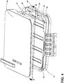
FIG. 4 is a detailed view of a portion of the lid assembly. -
FIG. 5 is a cross section taken of the lid assembly inFIG. 4 . -
FIG. 1 illustrates a perspective view of acomposting device 10 or a food recycler oriented in the vertical direction for transforming organic material into compost by way of a composting cycle of operation. Thecomposting device 10 can include ahousing 12 defining an interior having afront wall 14 spaced from aback wall 16, a pair ofside walls 17, and acontroller 18 located within thehousing 12. - A
top wall 20 can enclose thehousing 12 at the top of thefront wall 14,back wall 16, and the pair ofside walls 17. Thehousing 12 can be any structure for enclosing, supporting and protecting the electrical and mechanical components of thecomposting device 10 including, but not limited to a cabinet with a frame. - The
housing 12 further comprises alid assembly 28 which can include thetop wall 20 and adoor 22 slidably mounted to thehousing 12 for sliding movement between open or closed positions to enable access to the interior of thecomposting device 10. Thedoor 22 can be any barrier that provides selective access for inputting organic material into thecomposting device 10, including, but not limited to a hingedly, slidably or removably mounted cover, drawer, panel or lid. While shown inFIG. 1 as coupled to thetop wall 20, thedoor 22 can be mounted to any exterior wall enclosing thehousing 12 including, but not limited to thefront wall 14. - The
top wall 20, as well as the remainder of thehousing 12, can be formed of any material suitable for construction of the housing structure including, but not limited to metal such as steel or steel alloy, plastic, composite materials such as a hardened polymer composite material and combinations thereof. Some models ofcomposting devices 10 can include decorative panels that can be mounted on thehousing 12 or one or more walls. - When in the open position, the
door 22 provides access to the interior of thehousing 12. In the open position, the door can further expose any element of thecomposting device 10 interior of thehousing 12 including but not limited to one or more water fill inlets for supplying water to thecomposting device 10 and one or more enzyme dispenser inlets. Acomposter bin 24 is provided within thehousing 12 and includes a fill opening 23. Thecomposter bin 24 can be disposed beneath thedoor 22 such that the door provides selective access to the the fill opening 23 as the door is moved to the open position. - An
access drawer 26 is provided and slides in or out through an opening in thefront wall 14. Theaccess drawer 26 is a drawer slidably mounted to thehousing 12 on a horizontal axis for movement between open and closed positions. It will be understood, however, that access to the interior of thecomposting device 10 via thefront wall 14 can be provided in other ways, including but not limited to, a door pivotally connected to thefront wall 14. The access drawer can be detachably mounted to an internal side of thehousing 12 and is accessible from outside thehousing 12. Theaccess drawer 26 can be removable from the interior of thehousing 12 so that the contents thereof can be discharged at will by a user, as for example, by dumping the contents of thedrawer 26 onto a garden. - Operation of the
composting device 10 can be conventional and is not critical to the embodiments disclosed herein. For example, aconduit 29 can extend from thecomposter bin 24, such as from a lower portion of thecomposter bin 24, toward theaccess drawer 26. Embodiments of the disclosure can optionally include a transfer mechanism disposed inside theconduit 29 capable of assisting the transfer of material from thecomposter bin 24 to theaccess drawer 26. Examples of a transfer mechanism can include, but are not limited to, a rotatable auger, a conveyor, a gravitational chute, and the like. - A complete cycle of operation can include receiving organic material into the
composter bin 24, mixing the organic material within thecomposter bin 24 while simultaneously drying the organic material and then transferring the organic material to theaccess drawer 26 after which the composted organic material can be removed. A more complete exemplary description of the mechanisms involved in a complete cycle of operation for thecomposting device 10 can be found inUS application 15,064,969 - Referring now to
FIG. 2 , a schematic of thecontroller 18 for controlling the operation of thecomposting device 10 is illustrated. Thecontroller 18 can be provided with amemory 70 and a central processing unit (CPU) 72. Thememory 70 can be used for storing the control software that is executed by theCPU 72 in completing a cycle of operation using thecomposting device 10 and any additional software. Thememory 70 can also be used to store information, such as a database or table, and to store data received from one or more components of thecomposting device 10 that can be communicably coupled with thecontroller 18. - The
controller 18 can be operably coupled with one or more components of thecomposting device 10 for communicating with and controlling the operation of the component to complete a cycle of operation. For example, thecontroller 18 can be operably coupled with amotor 80 to control the operation of themotor 80. In another example, thecontroller 18 can be operably coupled to afan 82. Thecontroller 18 can also be coupled with one ormore sensors 84 provided in one or more of the systems of thecomposting device 10 to receive input from other sensors in thecomposting device 10. Thecontroller 18 can also be operably coupled to alid switch 86 to control locking a lid lock 90 (FIG. 3 ) within thecomposting device 10 when in operation and unlocking thecomposting device 10 when a cycle has completed. The controller can be operably coupled to a door closing switch 88 to provide an automatic closing of thedoor 22. -
FIG. 3 details the components of thelid assembly 28 of thecomposting device 10 in an exploded view. Thelid assembly 28 is provided on top of thehousing 12 for thecomposting device 10 such that when thedoor 22 is in an open position it provides direct access to the fill opening 23 of thecomposting bin 24. Thelid assembly 28 includes aremovable end plate 31 comprising abarrier portion 32 and afunnel 34. Thefunnel 34 defines an access opening 30 providing communication with the fill opening of thecomposter bin 24. Asealing surface 36 extends about the access opening 30 and, in some configurations, defines the access opening 30. In some configurations of thecomposting device 10, atrim bezel 38 can be placed on thefunnel 34 and is illustrated as being within thesealing surface 36. Thetrim bezel 38 can surround the access opening 30 such that together thetrim bezel 38 and thefunnel 34 collectively define the access opening 30 when thetrim bezel 38 is provided on thefunnel 34. - The
door 22 can comprise three parts, afascia 40, acarriage 42, and aseal 44. Theseal 44 can be mounted to thecarriage 42 wherein when thedoor 22 is slid closed along a slidingpath 45 theseal 44 comes in contact with the sealingsurface 36. In one implementation, theseal 44 is compressible and complementary in orientation to the sealingsurface 36 and is coated in an anti-friction coating. - The
fascia 40 can overlie and be mounted to at least a portion of anouter surface 46 of thecarriage 42. Thecarriage 42 can include atrack coupler 50 formed to be slidably mounted tocompound slide rails 48, though the slide rails can be any form of rail system including but not limited to dovetail slides, compound slides, and rack slides having friction bearing, ball bearing, or roller bearings. - Turning to
Figure 4 , the three parts of thedoor 22 are shown in more detail. Thecarriage 42 can includeopenings 52 formed to receive protrudingportions 54. Each protrudingportion 54 is formed on theseal 44 and shaped to be pushed one way throughopenings 52, for example but not limited to a snap, latch or hook end that link thecarriage 42 to theseal 44. - The
fascia 40 can be detachably mounted to thecarriage 42 with a releasable connection comprising asnap connection 56. While illustrated as protruding from thecarriage 42, thesnap connection 56 can comprise at least oneresilient hook 58 on a portion of thefascia 40 or thecarriage 42 so as to be received by a snap fitting (Figure 5 ) on the other of thecarriage 42 orfascia 40. -
Figure 5 is a section taken fromFigure 4 to illustrate the snap fitting 60 formed to receive theresilient hook 58. It can be contemplated that connecting thefascia 40 to thecarriage 42 can be done by other connection types for example but not limited to a slide and hook connection. - The
fascia 40 can be formed from a dishwasher safe material, for example but not limited to acrylonitrile butadiene styrene (ABS), melamine, nylon, polypropylene, or silicone, such that it retains its shape after being exposed to temperatures greater than 65°C for at least 180 minutes. The material can also have a static friction coefficient of less than 0.3 using the ASTM D1894 coefficient of friction testing method. - While illustrated as having the three parts of fascia, carriage, and seal, the door assembly can comprise more or less parts, three parts is for illustrative purposes and is not meant to be limiting. For example the fascia can be mounted to a pivoting portion for a door designed to pivot rather than slide having only the fascia and sealing portion totally two parts. While it can be further contemplated that the fascia is mounted to a pivoting portion having a seal mounting surface and a seal totally four parts.
- Benefits of a detachable fascia include both aesthetic and functional aspects. Aesthetically, a fascia creates a smooth surface free of undesirable edges or protrusions. A fascia that can be removed and replaced allows for updating colors or design when a user changes decor. Functionally a dishwasher safe fascia allows for cleaning including any harder to reach grooves or edges where food and debris can become lodged over time.
- To the extent not already described, the different features and structures of the various embodiments can be used in combination with each other as desired. That one feature cannot be illustrated in all of the embodiments is not meant to be construed that it cannot be, but is done for brevity of description.
- Further, while the invention has been specifically described in connection with certain specific embodiments thereof, it is to be understood that this is by way of illustration and not of limitation. In addition to the concepts covered by the below claims, the following concepts can also provide the basis for claims in any possible combinations:
- A food composter comprising a housing defining an interior and an access opening providing access to the interior, a composting bin located within the interior and having a fill opening aligned with the access opening, a door selectively closing the access opening and having an outer surface; and a fascia overlying at least a portion of the outer surface and having a snap connecting snap-fitting the fascia to the door.
- The food composter wherein the snap connection comprises at least one resilient hook on the fascia that snaps over a portion of the door.
- A food composter comprising a housing defining an interior and having an end plate with an access opening providing access to the interior, a composting bin located within the interior in a generally vertical orientation and having a fill opening aligned with the access opening, a door selectively closing the access opening and having an outer surface; and the door having a fascia overlying at least a portion of the outer surface and having a snap connecting snap-fitting the fascia to the door.
- The food composter wherein the snap connection comprises at least one resilient hook on the fascia that snaps over a portion of the door.
- The food composter wherein the composter bin is generally vertically oriented.
- This written description uses examples to disclose embodiments of the invention, and also to enable any person skilled in the art to practice embodiments of the invention, including making and using any devices or systems and performing any incorporated methods.
Claims (15)
- A food composter (10) comprising:a housing (12) defining an interior and an access opening (30) providing access to the interior;a composting bin (24) located within the interior and having a fill opening (23) aligned with the access opening (30);a door (22) selectively closing the access opening (30) and having an outer surface; and the door (22) having a fascia (40) overlying at least a portion of the outer surface (46) and detachably mounted to the door (22).
- The food composter (10) of claim 1 wherein the fascia (40) is made from dishwasher safe material.
- The food composter (10) of claim 2 wherein the dishwasher safe material retains its shape after being exposed to temperatures greater than 65°C for at least 180 minutes.
- The food composter (10) of claim 3 wherein the fascia (40) is made from a low friction material.
- The food composter (10) of claim 4 wherein the low friction material has a static friction coefficient of less than 0.3.
- The food composter (10) of any of the preceding claims wherein the fascia (40) is made from a material that retains its shape after being exposed to temperatures greater than 65°C for 180 minutes.
- The food composter (10) of any of the preceding claims wherein the fascia (40) is made from a low friction material has a static friction coefficient of less than 0.3.
- The food composter (10) of any of the preceding claims further comprising a releasable connection detachably mounting the fascia (40) to the door (22).
- The food composter (10) of claim 8 wherein the releasable connection comprises a snap connection (56).
- The food composter (10) of claim 9 wherein the snap connection (56) comprises at least one resilient hook (58) on one of the fascia (40) and door (22) that snaps over a portion of the other of the fascia (40) and the door (22).
- The food composter (10) of claim 10 wherein the resilient hook (58) is provided on the fascia (40).
- The food composter (10) of any of the preceding claims wherein the door (22) is slidably mounted to the housing (12).
- The food composter (10) of claim 12 wherein the door (22) comprises a carriage (42) slidably mounted to the housing (12) and the fascia (40) is mounted to the carriage (42).
- The food composter (10) of claim 13 comprising at least rail (48) slidably mounting the carriage (42) to the housing (12).
- The food composter (10) of any of the preceding claims wherein the housing (12) comprises an end plate (31) and the access opening (30) is located in the end plate (31).
Applications Claiming Priority (1)
| Application Number | Priority Date | Filing Date | Title |
|---|---|---|---|
| US15/158,660 US10590046B2 (en) | 2016-05-19 | 2016-05-19 | Composting device with door and fascia |
Publications (2)
| Publication Number | Publication Date |
|---|---|
| EP3246271A1 true EP3246271A1 (en) | 2017-11-22 |
| EP3246271B1 EP3246271B1 (en) | 2019-11-06 |
Family
ID=58266420
Family Applications (1)
| Application Number | Title | Priority Date | Filing Date |
|---|---|---|---|
| EP17159966.5A Active EP3246271B1 (en) | 2016-05-19 | 2017-03-08 | Composting device with door and fascia |
Country Status (2)
| Country | Link |
|---|---|
| US (1) | US10590046B2 (en) |
| EP (1) | EP3246271B1 (en) |
Families Citing this family (3)
| Publication number | Priority date | Publication date | Assignee | Title |
|---|---|---|---|---|
| US12605716B2 (en) | 2020-03-20 | 2026-04-21 | Bigz Tech Inc. | Organic waste processing device and method |
| EP4188171A1 (en) * | 2020-07-30 | 2023-06-07 | Kenwood Limited | Food processing appliance and fascia therefor |
| WO2024130446A1 (en) | 2022-12-22 | 2024-06-27 | Vcycene Inc. | System and method for automatically generating organic compost from waste |
Citations (3)
| Publication number | Priority date | Publication date | Assignee | Title |
|---|---|---|---|---|
| KR20090075306A (en) * | 2008-01-04 | 2009-07-08 | 김진혁 | Mini food handler. |
| WO2010090537A2 (en) * | 2009-02-05 | 2010-08-12 | Benjamin Bell | A continuous flow worm farm |
| US20150031123A1 (en) * | 2013-07-29 | 2015-01-29 | Whirlpool Corporation | Composting device |
Family Cites Families (20)
| Publication number | Priority date | Publication date | Assignee | Title |
|---|---|---|---|---|
| US3773399A (en) * | 1972-03-27 | 1973-11-20 | Whirlpool Co | Front panel construction for refuse compactor drawer |
| DE3376975D1 (en) | 1982-08-20 | 1988-07-14 | Calmic Gmbh | HYGIENICAL RECEPTACLE |
| US4732431A (en) * | 1986-05-21 | 1988-03-22 | Whirlpool Corporation | Interchangeable door panels for dishwasher |
| GB9022428D0 (en) | 1990-10-16 | 1990-11-28 | Pelowski Paul | Compartmentalised recyclable waste container |
| GB9122079D0 (en) * | 1991-10-17 | 1991-11-27 | J E S Arnold Domestic Applianc | A door for a domestic electrical appliance |
| DE4430777C2 (en) * | 1994-08-30 | 1996-07-11 | Rudolf Ebner | Waste lock for garbage cans or garbage boxes |
| US7108414B2 (en) * | 1995-06-27 | 2006-09-19 | Solid State Opto Limited | Light emitting panel assemblies |
| DE19803374A1 (en) | 1998-01-29 | 1999-08-05 | Adalbert Schwarzberg | Refuse container with sliding interlocking lid |
| US6736470B2 (en) * | 2001-10-05 | 2004-05-18 | Maytag Corporation | Molded plastic dishwasher door assembly |
| US6840773B2 (en) * | 2002-03-07 | 2005-01-11 | Jan Anderson | Decorative magnetic sheet and method for decorating an appliance |
| WO2004024355A1 (en) | 2002-09-13 | 2004-03-25 | Whirlpool Canada Inc. | Device and process for processing organic waste |
| US7014281B2 (en) * | 2003-04-10 | 2006-03-21 | Maytag Corporation | Fully integrated dishwasher door |
| US6921661B2 (en) * | 2003-09-08 | 2005-07-26 | Ideas That Grow Inc. | Composting device |
| KR20110073656A (en) | 2009-12-24 | 2011-06-30 | 박준국 | Food waste bin |
| IT1399963B1 (en) | 2010-05-17 | 2013-05-09 | Iacobucci Hf Electronics S P A | WASTE COMPACTOR |
| USD658839S1 (en) | 2011-05-03 | 2012-05-01 | Nature Mill, Inc. | Compost machine |
| US20130217111A1 (en) | 2012-02-21 | 2013-08-22 | Ta Ya Kitchen Utensil Co., Ltd | Waste Disposal Device |
| CN204355578U (en) | 2014-11-07 | 2015-05-27 | 江门市新会正华五金制品有限公司 | A kind of sewage disposer |
| US10047018B2 (en) * | 2016-03-09 | 2018-08-14 | Whirlpool Corporation | Composting device sliding lid with a seal assembly |
| US10035734B2 (en) | 2016-03-10 | 2018-07-31 | James Chun Koh | Food waste treatment apparatus |
-
2016
- 2016-05-19 US US15/158,660 patent/US10590046B2/en active Active
-
2017
- 2017-03-08 EP EP17159966.5A patent/EP3246271B1/en active Active
Patent Citations (3)
| Publication number | Priority date | Publication date | Assignee | Title |
|---|---|---|---|---|
| KR20090075306A (en) * | 2008-01-04 | 2009-07-08 | 김진혁 | Mini food handler. |
| WO2010090537A2 (en) * | 2009-02-05 | 2010-08-12 | Benjamin Bell | A continuous flow worm farm |
| US20150031123A1 (en) * | 2013-07-29 | 2015-01-29 | Whirlpool Corporation | Composting device |
Also Published As
| Publication number | Publication date |
|---|---|
| US10590046B2 (en) | 2020-03-17 |
| US20170334799A1 (en) | 2017-11-23 |
| EP3246271B1 (en) | 2019-11-06 |
Similar Documents
| Publication | Publication Date | Title |
|---|---|---|
| US11667589B2 (en) | Composting device with trim bezel | |
| US11753350B2 (en) | Composting device sliding lid with a seal assembly | |
| USD577719S1 (en) | Computer having a door | |
| EP3246271B1 (en) | Composting device with door and fascia | |
| AU2010218207B2 (en) | Selectable presentation of dual-bin system | |
| US11702375B2 (en) | Food waste recycling appliance | |
| CA2847978C (en) | Dispensing cabinet and method for the controlled dispensing of objects | |
| EP3275808A1 (en) | Method for cleaning a food waste recycling bin of a food waste recycling appliance | |
| US20070235452A1 (en) | Storage container lid | |
| USD572212S1 (en) | Equipment control cabinet for washing station or the like | |
| US20190281979A1 (en) | Storage unit with adjustably-sized compartments and smart locker using same | |
| EP1526485A3 (en) | A beverage vending machine installation | |
| KR100886327B1 (en) | Food waste bin switchgear using waste discharge chip | |
| US20080179203A1 (en) | Tool Box with Integrated Work Bench | |
| CN109956147A (en) | The device of factory's storage express delivery | |
| AU2006331455B2 (en) | Dishwasher with an improved arrangement of the feed device in the door | |
| GB2360998A (en) | Secure delivery apparatus | |
| US8388042B2 (en) | Integrated door and shelving system | |
| US20070273257A1 (en) | Cabinet Receptacle Apparatus and System | |
| KR100536396B1 (en) | Structure for Fetching Door of Food Garbage Disposer | |
| US20060214546A1 (en) | Feed center | |
| JPH02254043A (en) | Cabinet for vehicle | |
| WO2015087236A1 (en) | Electronic equipment for managing an industrial automation system | |
| DE102022200427A1 (en) | Food storage container with an additional container attached to a coupling cam, and domestic refrigeration appliance | |
| DE102012112517A1 (en) | Dish rinsing machine i.e. household dish washer, for cleaning utensils, has front panel pivotably arranged at outer side of rinsing chamber door, where front panel is formed as plate of door leaf |
Legal Events
| Date | Code | Title | Description |
|---|---|---|---|
| PUAI | Public reference made under article 153(3) epc to a published international application that has entered the european phase |
Free format text: ORIGINAL CODE: 0009012 |
|
| STAA | Information on the status of an ep patent application or granted ep patent |
Free format text: STATUS: THE APPLICATION HAS BEEN PUBLISHED |
|
| AK | Designated contracting states |
Kind code of ref document: A1 Designated state(s): AL AT BE BG CH CY CZ DE DK EE ES FI FR GB GR HR HU IE IS IT LI LT LU LV MC MK MT NL NO PL PT RO RS SE SI SK SM TR |
|
| AX | Request for extension of the european patent |
Extension state: BA ME |
|
| STAA | Information on the status of an ep patent application or granted ep patent |
Free format text: STATUS: REQUEST FOR EXAMINATION WAS MADE |
|
| 17P | Request for examination filed |
Effective date: 20180502 |
|
| RBV | Designated contracting states (corrected) |
Designated state(s): AL AT BE BG CH CY CZ DE DK EE ES FI FR GB GR HR HU IE IS IT LI LT LU LV MC MK MT NL NO PL PT RO RS SE SI SK SM TR |
|
| STAA | Information on the status of an ep patent application or granted ep patent |
Free format text: STATUS: EXAMINATION IS IN PROGRESS |
|
| 17Q | First examination report despatched |
Effective date: 20180921 |
|
| GRAP | Despatch of communication of intention to grant a patent |
Free format text: ORIGINAL CODE: EPIDOSNIGR1 |
|
| STAA | Information on the status of an ep patent application or granted ep patent |
Free format text: STATUS: GRANT OF PATENT IS INTENDED |
|
| INTG | Intention to grant announced |
Effective date: 20190823 |
|
| GRAS | Grant fee paid |
Free format text: ORIGINAL CODE: EPIDOSNIGR3 |
|
| GRAA | (expected) grant |
Free format text: ORIGINAL CODE: 0009210 |
|
| STAA | Information on the status of an ep patent application or granted ep patent |
Free format text: STATUS: THE PATENT HAS BEEN GRANTED |
|
| AK | Designated contracting states |
Kind code of ref document: B1 Designated state(s): AL AT BE BG CH CY CZ DE DK EE ES FI FR GB GR HR HU IE IS IT LI LT LU LV MC MK MT NL NO PL PT RO RS SE SI SK SM TR |
|
| REG | Reference to a national code |
Ref country code: GB Ref legal event code: FG4D |
|
| REG | Reference to a national code |
Ref country code: CH Ref legal event code: EP Ref country code: AT Ref legal event code: REF Ref document number: 1198482 Country of ref document: AT Kind code of ref document: T Effective date: 20191115 |
|
| REG | Reference to a national code |
Ref country code: IE Ref legal event code: FG4D |
|
| REG | Reference to a national code |
Ref country code: DE Ref legal event code: R096 Ref document number: 602017008319 Country of ref document: DE |
|
| REG | Reference to a national code |
Ref country code: NL Ref legal event code: MP Effective date: 20191106 |
|
| REG | Reference to a national code |
Ref country code: LT Ref legal event code: MG4D |
|
| PG25 | Lapsed in a contracting state [announced via postgrant information from national office to epo] |
Ref country code: FI Free format text: LAPSE BECAUSE OF FAILURE TO SUBMIT A TRANSLATION OF THE DESCRIPTION OR TO PAY THE FEE WITHIN THE PRESCRIBED TIME-LIMIT Effective date: 20191106 Ref country code: BG Free format text: LAPSE BECAUSE OF FAILURE TO SUBMIT A TRANSLATION OF THE DESCRIPTION OR TO PAY THE FEE WITHIN THE PRESCRIBED TIME-LIMIT Effective date: 20200206 Ref country code: NO Free format text: LAPSE BECAUSE OF FAILURE TO SUBMIT A TRANSLATION OF THE DESCRIPTION OR TO PAY THE FEE WITHIN THE PRESCRIBED TIME-LIMIT Effective date: 20200206 Ref country code: LV Free format text: LAPSE BECAUSE OF FAILURE TO SUBMIT A TRANSLATION OF THE DESCRIPTION OR TO PAY THE FEE WITHIN THE PRESCRIBED TIME-LIMIT Effective date: 20191106 Ref country code: PT Free format text: LAPSE BECAUSE OF FAILURE TO SUBMIT A TRANSLATION OF THE DESCRIPTION OR TO PAY THE FEE WITHIN THE PRESCRIBED TIME-LIMIT Effective date: 20200306 Ref country code: SE Free format text: LAPSE BECAUSE OF FAILURE TO SUBMIT A TRANSLATION OF THE DESCRIPTION OR TO PAY THE FEE WITHIN THE PRESCRIBED TIME-LIMIT Effective date: 20191106 Ref country code: PL Free format text: LAPSE BECAUSE OF FAILURE TO SUBMIT A TRANSLATION OF THE DESCRIPTION OR TO PAY THE FEE WITHIN THE PRESCRIBED TIME-LIMIT Effective date: 20191106 Ref country code: NL Free format text: LAPSE BECAUSE OF FAILURE TO SUBMIT A TRANSLATION OF THE DESCRIPTION OR TO PAY THE FEE WITHIN THE PRESCRIBED TIME-LIMIT Effective date: 20191106 Ref country code: GR Free format text: LAPSE BECAUSE OF FAILURE TO SUBMIT A TRANSLATION OF THE DESCRIPTION OR TO PAY THE FEE WITHIN THE PRESCRIBED TIME-LIMIT Effective date: 20200207 Ref country code: LT Free format text: LAPSE BECAUSE OF FAILURE TO SUBMIT A TRANSLATION OF THE DESCRIPTION OR TO PAY THE FEE WITHIN THE PRESCRIBED TIME-LIMIT Effective date: 20191106 |
|
| PG25 | Lapsed in a contracting state [announced via postgrant information from national office to epo] |
Ref country code: IS Free format text: LAPSE BECAUSE OF FAILURE TO SUBMIT A TRANSLATION OF THE DESCRIPTION OR TO PAY THE FEE WITHIN THE PRESCRIBED TIME-LIMIT Effective date: 20200306 Ref country code: HR Free format text: LAPSE BECAUSE OF FAILURE TO SUBMIT A TRANSLATION OF THE DESCRIPTION OR TO PAY THE FEE WITHIN THE PRESCRIBED TIME-LIMIT Effective date: 20191106 Ref country code: RS Free format text: LAPSE BECAUSE OF FAILURE TO SUBMIT A TRANSLATION OF THE DESCRIPTION OR TO PAY THE FEE WITHIN THE PRESCRIBED TIME-LIMIT Effective date: 20191106 |
|
| PG25 | Lapsed in a contracting state [announced via postgrant information from national office to epo] |
Ref country code: AL Free format text: LAPSE BECAUSE OF FAILURE TO SUBMIT A TRANSLATION OF THE DESCRIPTION OR TO PAY THE FEE WITHIN THE PRESCRIBED TIME-LIMIT Effective date: 20191106 |
|
| PG25 | Lapsed in a contracting state [announced via postgrant information from national office to epo] |
Ref country code: ES Free format text: LAPSE BECAUSE OF FAILURE TO SUBMIT A TRANSLATION OF THE DESCRIPTION OR TO PAY THE FEE WITHIN THE PRESCRIBED TIME-LIMIT Effective date: 20191106 Ref country code: DK Free format text: LAPSE BECAUSE OF FAILURE TO SUBMIT A TRANSLATION OF THE DESCRIPTION OR TO PAY THE FEE WITHIN THE PRESCRIBED TIME-LIMIT Effective date: 20191106 Ref country code: EE Free format text: LAPSE BECAUSE OF FAILURE TO SUBMIT A TRANSLATION OF THE DESCRIPTION OR TO PAY THE FEE WITHIN THE PRESCRIBED TIME-LIMIT Effective date: 20191106 Ref country code: RO Free format text: LAPSE BECAUSE OF FAILURE TO SUBMIT A TRANSLATION OF THE DESCRIPTION OR TO PAY THE FEE WITHIN THE PRESCRIBED TIME-LIMIT Effective date: 20191106 Ref country code: CZ Free format text: LAPSE BECAUSE OF FAILURE TO SUBMIT A TRANSLATION OF THE DESCRIPTION OR TO PAY THE FEE WITHIN THE PRESCRIBED TIME-LIMIT Effective date: 20191106 |
|
| REG | Reference to a national code |
Ref country code: DE Ref legal event code: R097 Ref document number: 602017008319 Country of ref document: DE |
|
| REG | Reference to a national code |
Ref country code: AT Ref legal event code: MK05 Ref document number: 1198482 Country of ref document: AT Kind code of ref document: T Effective date: 20191106 |
|
| PG25 | Lapsed in a contracting state [announced via postgrant information from national office to epo] |
Ref country code: SM Free format text: LAPSE BECAUSE OF FAILURE TO SUBMIT A TRANSLATION OF THE DESCRIPTION OR TO PAY THE FEE WITHIN THE PRESCRIBED TIME-LIMIT Effective date: 20191106 Ref country code: SK Free format text: LAPSE BECAUSE OF FAILURE TO SUBMIT A TRANSLATION OF THE DESCRIPTION OR TO PAY THE FEE WITHIN THE PRESCRIBED TIME-LIMIT Effective date: 20191106 |
|
| PLBE | No opposition filed within time limit |
Free format text: ORIGINAL CODE: 0009261 |
|
| STAA | Information on the status of an ep patent application or granted ep patent |
Free format text: STATUS: NO OPPOSITION FILED WITHIN TIME LIMIT |
|
| 26N | No opposition filed |
Effective date: 20200807 |
|
| PG25 | Lapsed in a contracting state [announced via postgrant information from national office to epo] |
Ref country code: MC Free format text: LAPSE BECAUSE OF FAILURE TO SUBMIT A TRANSLATION OF THE DESCRIPTION OR TO PAY THE FEE WITHIN THE PRESCRIBED TIME-LIMIT Effective date: 20191106 |
|
| REG | Reference to a national code |
Ref country code: CH Ref legal event code: PL |
|
| PG25 | Lapsed in a contracting state [announced via postgrant information from national office to epo] |
Ref country code: AT Free format text: LAPSE BECAUSE OF FAILURE TO SUBMIT A TRANSLATION OF THE DESCRIPTION OR TO PAY THE FEE WITHIN THE PRESCRIBED TIME-LIMIT Effective date: 20191106 Ref country code: SI Free format text: LAPSE BECAUSE OF FAILURE TO SUBMIT A TRANSLATION OF THE DESCRIPTION OR TO PAY THE FEE WITHIN THE PRESCRIBED TIME-LIMIT Effective date: 20191106 |
|
| REG | Reference to a national code |
Ref country code: BE Ref legal event code: MM Effective date: 20200331 |
|
| PG25 | Lapsed in a contracting state [announced via postgrant information from national office to epo] |
Ref country code: LU Free format text: LAPSE BECAUSE OF NON-PAYMENT OF DUE FEES Effective date: 20200308 |
|
| PG25 | Lapsed in a contracting state [announced via postgrant information from national office to epo] |
Ref country code: IE Free format text: LAPSE BECAUSE OF NON-PAYMENT OF DUE FEES Effective date: 20200308 Ref country code: LI Free format text: LAPSE BECAUSE OF NON-PAYMENT OF DUE FEES Effective date: 20200331 Ref country code: CH Free format text: LAPSE BECAUSE OF NON-PAYMENT OF DUE FEES Effective date: 20200331 |
|
| PG25 | Lapsed in a contracting state [announced via postgrant information from national office to epo] |
Ref country code: BE Free format text: LAPSE BECAUSE OF NON-PAYMENT OF DUE FEES Effective date: 20200331 |
|
| PG25 | Lapsed in a contracting state [announced via postgrant information from national office to epo] |
Ref country code: TR Free format text: LAPSE BECAUSE OF FAILURE TO SUBMIT A TRANSLATION OF THE DESCRIPTION OR TO PAY THE FEE WITHIN THE PRESCRIBED TIME-LIMIT Effective date: 20191106 Ref country code: MT Free format text: LAPSE BECAUSE OF FAILURE TO SUBMIT A TRANSLATION OF THE DESCRIPTION OR TO PAY THE FEE WITHIN THE PRESCRIBED TIME-LIMIT Effective date: 20191106 Ref country code: CY Free format text: LAPSE BECAUSE OF FAILURE TO SUBMIT A TRANSLATION OF THE DESCRIPTION OR TO PAY THE FEE WITHIN THE PRESCRIBED TIME-LIMIT Effective date: 20191106 |
|
| PG25 | Lapsed in a contracting state [announced via postgrant information from national office to epo] |
Ref country code: MK Free format text: LAPSE BECAUSE OF FAILURE TO SUBMIT A TRANSLATION OF THE DESCRIPTION OR TO PAY THE FEE WITHIN THE PRESCRIBED TIME-LIMIT Effective date: 20191106 |
|
| PGFP | Annual fee paid to national office [announced via postgrant information from national office to epo] |
Ref country code: FR Payment date: 20230110 Year of fee payment: 7 |
|
| PGFP | Annual fee paid to national office [announced via postgrant information from national office to epo] |
Ref country code: IT Payment date: 20230213 Year of fee payment: 7 Ref country code: GB Payment date: 20230112 Year of fee payment: 7 Ref country code: DE Payment date: 20230110 Year of fee payment: 7 |
|
| P01 | Opt-out of the competence of the unified patent court (upc) registered |
Effective date: 20230522 |
|
| REG | Reference to a national code |
Ref country code: DE Ref legal event code: R119 Ref document number: 602017008319 Country of ref document: DE |
|
| GBPC | Gb: european patent ceased through non-payment of renewal fee |
Effective date: 20240308 |
|
| PG25 | Lapsed in a contracting state [announced via postgrant information from national office to epo] |
Ref country code: DE Free format text: LAPSE BECAUSE OF NON-PAYMENT OF DUE FEES Effective date: 20241001 |
|
| PG25 | Lapsed in a contracting state [announced via postgrant information from national office to epo] |
Ref country code: GB Free format text: LAPSE BECAUSE OF NON-PAYMENT OF DUE FEES Effective date: 20240308 |
|
| PG25 | Lapsed in a contracting state [announced via postgrant information from national office to epo] |
Ref country code: FR Free format text: LAPSE BECAUSE OF NON-PAYMENT OF DUE FEES Effective date: 20240331 |
|
| PG25 | Lapsed in a contracting state [announced via postgrant information from national office to epo] |
Ref country code: GB Free format text: LAPSE BECAUSE OF NON-PAYMENT OF DUE FEES Effective date: 20240308 Ref country code: FR Free format text: LAPSE BECAUSE OF NON-PAYMENT OF DUE FEES Effective date: 20240331 Ref country code: DE Free format text: LAPSE BECAUSE OF NON-PAYMENT OF DUE FEES Effective date: 20241001 |
|
| PG25 | Lapsed in a contracting state [announced via postgrant information from national office to epo] |
Ref country code: IT Free format text: LAPSE BECAUSE OF NON-PAYMENT OF DUE FEES Effective date: 20240308 |