EP3246258A1 - Can filling/seaming device and can filling/seaming method - Google Patents
Can filling/seaming device and can filling/seaming method Download PDFInfo
- Publication number
- EP3246258A1 EP3246258A1 EP15878011.4A EP15878011A EP3246258A1 EP 3246258 A1 EP3246258 A1 EP 3246258A1 EP 15878011 A EP15878011 A EP 15878011A EP 3246258 A1 EP3246258 A1 EP 3246258A1
- Authority
- EP
- European Patent Office
- Prior art keywords
- turret
- filling
- forwarding
- seaming
- seamer
- Prior art date
- Legal status (The legal status is an assumption and is not a legal conclusion. Google has not performed a legal analysis and makes no representation as to the accuracy of the status listed.)
- Granted
Links
Images


Classifications
-
- B—PERFORMING OPERATIONS; TRANSPORTING
- B67—OPENING, CLOSING OR CLEANING BOTTLES, JARS OR SIMILAR CONTAINERS; LIQUID HANDLING
- B67B—APPLYING CLOSURE MEMBERS TO BOTTLES JARS, OR SIMILAR CONTAINERS; OPENING CLOSED CONTAINERS
- B67B3/00—Closing bottles, jars or similar containers by applying caps
- B67B3/02—Closing bottles, jars or similar containers by applying caps by applying flanged caps, e.g. crown caps, and securing by deformation of flanges
- B67B3/06—Feeding caps to capping heads
-
- B—PERFORMING OPERATIONS; TRANSPORTING
- B21—MECHANICAL METAL-WORKING WITHOUT ESSENTIALLY REMOVING MATERIAL; PUNCHING METAL
- B21D—WORKING OR PROCESSING OF SHEET METAL OR METAL TUBES, RODS OR PROFILES WITHOUT ESSENTIALLY REMOVING MATERIAL; PUNCHING METAL
- B21D51/00—Making hollow objects
- B21D51/16—Making hollow objects characterised by the use of the objects
- B21D51/26—Making hollow objects characterised by the use of the objects cans or tins; Closing same in a permanent manner
- B21D51/30—Folding the circumferential seam
- B21D51/32—Folding the circumferential seam by rolling
-
- B—PERFORMING OPERATIONS; TRANSPORTING
- B21—MECHANICAL METAL-WORKING WITHOUT ESSENTIALLY REMOVING MATERIAL; PUNCHING METAL
- B21D—WORKING OR PROCESSING OF SHEET METAL OR METAL TUBES, RODS OR PROFILES WITHOUT ESSENTIALLY REMOVING MATERIAL; PUNCHING METAL
- B21D51/00—Making hollow objects
- B21D51/16—Making hollow objects characterised by the use of the objects
- B21D51/26—Making hollow objects characterised by the use of the objects cans or tins; Closing same in a permanent manner
- B21D51/2653—Methods or machines for closing cans by applying caps or bottoms
- B21D51/2661—Sealing or closing means therefor
-
- B—PERFORMING OPERATIONS; TRANSPORTING
- B21—MECHANICAL METAL-WORKING WITHOUT ESSENTIALLY REMOVING MATERIAL; PUNCHING METAL
- B21D—WORKING OR PROCESSING OF SHEET METAL OR METAL TUBES, RODS OR PROFILES WITHOUT ESSENTIALLY REMOVING MATERIAL; PUNCHING METAL
- B21D51/00—Making hollow objects
- B21D51/16—Making hollow objects characterised by the use of the objects
- B21D51/26—Making hollow objects characterised by the use of the objects cans or tins; Closing same in a permanent manner
- B21D51/30—Folding the circumferential seam
-
- B—PERFORMING OPERATIONS; TRANSPORTING
- B65—CONVEYING; PACKING; STORING; HANDLING THIN OR FILAMENTARY MATERIAL
- B65B—MACHINES, APPARATUS OR DEVICES FOR, OR METHODS OF, PACKAGING ARTICLES OR MATERIALS; UNPACKING
- B65B7/00—Closing containers or receptacles after filling
- B65B7/16—Closing semi-rigid or rigid containers or receptacles not deformed by, or not taking-up shape of, contents, e.g. boxes or cartons
- B65B7/28—Closing semi-rigid or rigid containers or receptacles not deformed by, or not taking-up shape of, contents, e.g. boxes or cartons by applying separate preformed closures, e.g. lids, covers
-
- B—PERFORMING OPERATIONS; TRANSPORTING
- B67—OPENING, CLOSING OR CLEANING BOTTLES, JARS OR SIMILAR CONTAINERS; LIQUID HANDLING
- B67B—APPLYING CLOSURE MEMBERS TO BOTTLES JARS, OR SIMILAR CONTAINERS; OPENING CLOSED CONTAINERS
- B67B3/00—Closing bottles, jars or similar containers by applying caps
- B67B3/02—Closing bottles, jars or similar containers by applying caps by applying flanged caps, e.g. crown caps, and securing by deformation of flanges
-
- B—PERFORMING OPERATIONS; TRANSPORTING
- B67—OPENING, CLOSING OR CLEANING BOTTLES, JARS OR SIMILAR CONTAINERS; LIQUID HANDLING
- B67C—CLEANING, FILLING WITH LIQUIDS OR SEMILIQUIDS, OR EMPTYING, OF BOTTLES, JARS, CANS, CASKS, BARRELS, OR SIMILAR CONTAINERS, NOT OTHERWISE PROVIDED FOR; FUNNELS
- B67C3/00—Bottling liquids or semiliquids; Filling jars or cans with liquids or semiliquids using bottling or like apparatus; Filling casks or barrels with liquids or semiliquids
- B67C3/02—Bottling liquids or semiliquids; Filling jars or cans with liquids or semiliquids using bottling or like apparatus
- B67C3/22—Details
- B67C3/222—Head-space air removing devices, e.g. by inducing foam
-
- B—PERFORMING OPERATIONS; TRANSPORTING
- B67—OPENING, CLOSING OR CLEANING BOTTLES, JARS OR SIMILAR CONTAINERS; LIQUID HANDLING
- B67C—CLEANING, FILLING WITH LIQUIDS OR SEMILIQUIDS, OR EMPTYING, OF BOTTLES, JARS, CANS, CASKS, BARRELS, OR SIMILAR CONTAINERS, NOT OTHERWISE PROVIDED FOR; FUNNELS
- B67C7/00—Concurrent cleaning, filling, and closing of bottles; Processes or devices for at least two of these operations
- B67C7/0006—Conveying; Synchronising
- B67C7/004—Conveying; Synchronising the containers travelling along a circular path
- B67C7/0046—Infeed and outfeed devices
-
- B—PERFORMING OPERATIONS; TRANSPORTING
- B65—CONVEYING; PACKING; STORING; HANDLING THIN OR FILAMENTARY MATERIAL
- B65B—MACHINES, APPARATUS OR DEVICES FOR, OR METHODS OF, PACKAGING ARTICLES OR MATERIALS; UNPACKING
- B65B57/00—Automatic control, checking, warning, or safety devices
- B65B57/10—Automatic control, checking, warning, or safety devices responsive to absence, presence, abnormal feed, or misplacement of articles or materials to be packaged
- B65B57/14—Automatic control, checking, warning, or safety devices responsive to absence, presence, abnormal feed, or misplacement of articles or materials to be packaged and operating to control, or stop, the feed of articles or material to be packaged
-
- B—PERFORMING OPERATIONS; TRANSPORTING
- B67—OPENING, CLOSING OR CLEANING BOTTLES, JARS OR SIMILAR CONTAINERS; LIQUID HANDLING
- B67C—CLEANING, FILLING WITH LIQUIDS OR SEMILIQUIDS, OR EMPTYING, OF BOTTLES, JARS, CANS, CASKS, BARRELS, OR SIMILAR CONTAINERS, NOT OTHERWISE PROVIDED FOR; FUNNELS
- B67C3/00—Bottling liquids or semiliquids; Filling jars or cans with liquids or semiliquids using bottling or like apparatus; Filling casks or barrels with liquids or semiliquids
- B67C3/02—Bottling liquids or semiliquids; Filling jars or cans with liquids or semiliquids using bottling or like apparatus
- B67C3/06—Bottling liquids or semiliquids; Filling jars or cans with liquids or semiliquids using bottling or like apparatus using counterpressure, i.e. filling while the container is under pressure
- B67C3/12—Pressure-control devices
-
- B—PERFORMING OPERATIONS; TRANSPORTING
- B67—OPENING, CLOSING OR CLEANING BOTTLES, JARS OR SIMILAR CONTAINERS; LIQUID HANDLING
- B67C—CLEANING, FILLING WITH LIQUIDS OR SEMILIQUIDS, OR EMPTYING, OF BOTTLES, JARS, CANS, CASKS, BARRELS, OR SIMILAR CONTAINERS, NOT OTHERWISE PROVIDED FOR; FUNNELS
- B67C3/00—Bottling liquids or semiliquids; Filling jars or cans with liquids or semiliquids using bottling or like apparatus; Filling casks or barrels with liquids or semiliquids
- B67C3/02—Bottling liquids or semiliquids; Filling jars or cans with liquids or semiliquids using bottling or like apparatus
- B67C3/22—Details
Definitions
- the present invention relates to a can filling/seaming device and a can filling/seaming method for filling a can with a content and seaming a lid to a can.
- a conventional filling/seaming device includes a rotary filling machine (filler) that successively fills a can of a metal material with a liquid content such as a beverage, and a seaming machine (seamer) that successively seals a lid (metal lid) to a flange part of the filled can by seaming.
- a filler generally used has a plurality of holding parts (pockets) provided at the circular outer circumference of a rotating filling turret to receive and hold a can, and a filling nozzle that moves in synchronization with each of the holding parts is provided above the holding part.
- Successively supplied cans are sequentially held by the filling turret of the filler and then filled with a prescribed amount of liquid content from the respective filling nozzles while being conveyed by the rotation of the filling turret.
- the filled cans once removed from the filling turret are transported to a feeding conveyer or a hook-up conveyer and conveyed to the seamer.
- the seamer sequentially supplies lids to the flange parts of the filled cans supplied from the feed conveyer or the hook-up conveyer, and the flange parts of the cans and the curled parts of the lids are joined by double-seaming by roll processing, so that the lids are attached and sealed to the cans (see PTL 1).
- the filling/seaming devices are designed in various forms for different uses, and particularly when a can filled with a liquid content is sealed with a lid by seaming, it is inevitable to take precautions to prevent the content from spilling from the can in a conveyance path between the filling of the content and the seaming with the lid.
- the conventional filling/seaming device described above has a relatively long linear intermediate conveyance path by a feeding conveyer or a hook-up conveyer between the filler and the seamer, so that the can filled with the content is not subject to high acceleration or centrifugal force during the conveyance in the path.
- an object of the invention is to allow the filler and the seamer to be integrated in a compact arrangement in a can filling/seaming device and a can filling/seaming method for filling a can with a liquid content and seaming a lid
- another object is to simplify installation works and reduce the number of days for the device to be set up for operation by eliminating the necessity of positional adjustment and timing adjustment during transport from the filler to the intermediate conveyance path and from the intermediate conveyance path to the seamer
- yet another object is to reduce works related to timing deviation inspection and timing adjustment in daily use
- a still further object is to reduce the manufacturing cost by eliminating the necessity of using a special driving device for timing adjustment.
- a can filling/seaming device and a can filling/seaming method according to the present invention includes the following features.
- the can filling/seaming device includes a filler that fills a can with a liquid content while conveying the can by rotation of a filling turret, a seamer that attaches a lid to the can filled with the content by double-seaming, and a forwarding turret provided between a carrying-out position of the filling turret and a carrying-in position to the seamer to circularly convey the can filled with the content, wherein a lid supply part is provided on the forwarding turret.
- the can filling/seaming method includes filling a can with a liquid content while conveying the can along a circular conveyance path of a filling turret, transporting the can filled with the content from the filling turret to a forwarding turret and supplying the can with a lid while conveying the can along a circular conveyance path of the forwarding turret, and transporting the can supplied with the lid from the forwarding turret to a seamer and attaching the lid to the can by double-seaming while conveying the can along a circular conveyance path of the seamer.
- a filler that fills the can with the content and the seamer that seams the lid to the can may be integrated through a forwarding turret in a compact arrangement, so that the installation area can be reduced.
- acceleration curvature
- the installation area can be reduced while keeping high filling accuracy.
- Positional adjustment and timing adjustment during transport from the filler to the forwarding turret or from the forwarding turret to the seamer can be abolished, so that installation works can be simplified and the number of days for the device to be set up for operation can be reduced. In daily use, works related to timing deviation inspection or timing adjustment can be reduced, and use of a special driving device for timing adjustment is not necessary, which can lower the manufacturing cost.
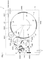
- a can filling/seaming device 1 includes a filler 2, a seamer 3, and a forwarding turret 4.
- the can W to be described herein is a can having a flange part at the open end, and W1 designates an empty can, W2 designates a can that is being filled with a liquid content such as a beverage or is already filled with the content, and W3 designates a can sealed with a lid by double-seaming in the drawings.
- the filler 2 includes a filling turret 20 and fills a can W with a liquid content while conveying the can W by rotation of the filling turret 20.
- the filling turret 20 includes a plurality of pockets 2P that hold cans W at its circular outer circumference, and the pockets 2P are arranged at a set conveyance pitch P1 in a circular conveyance path L1 with a pitch diameter D1.
- a filling nozzle (not shown) that moves in synchronization with each of the pockets 2P is provided above the pocket 2P, and the filling nozzle fills the can W with a liquid content between the carrying-in position 20A and the carrying-out position 20B of the filling turret 20.
- the can W (empty can W1) is supplied to the filler 2 via an appropriate carrying-in path L in from a rinser that cleans the cans W.
- a carrying-in turret 22 that receives and delivers the cans W to the pockets 2P of the filling turret 20 or a rinser turret (not shown) that cleans the cans W may be additionally provided to the carrying-in turret 22.
- the seamer 3 attaches a lid to the flange part of the can filled with the content, by double-seaming by roll processing, and while a can W, on which a lid is placed, is conveyed in a circular conveyance path L2 from a carrying-in position 3A to a carrying-out position 3B, the flange part of the can and the curled part of the lid are subjected to double-seaming by roll processing, so that the can W is sealed.
- a pitch diameter D2 and a conveyance pitch P2 are set as appropriate in the circular conveyance path L2 of the seamer 3.
- the can W carried out from the seamer 3 is carried outside the device via an appropriate carrying-out path L out .
- a discharging turret 30 that receives and forwards the can W discharged from the seamer 3 while rotating in the direction of the shown arrow may be provided, or an inspector turret 31 that carries out various kinds of inspection including inspection about a filling amount with respect to the can W discharged from the discharging turret 30 may be provided.
- two forwarding turrets 4A and 4B are provided between the carrying-out position 20B of the filling turret 20 and the carrying-in position 3A of the seamer 3 and circularly convey the can W filled with the content, and pockets 4P are provided at respective conveyance pitches P3A and P3B in the circular conveyance paths L3A and L3B with respective pitch diameters D3A and D3B.
- the pitch diameters D3A and D3B of the forwarding turrets 4A and 4B are equal and the conveyance pitches P3A and P3B are equal in this example, the arrangement is not limited to the above.
- the forwarding turret 4B between the forwarding turrets 4A and 4B is provided with a lid supply part 40 in the circular conveyance path L3B.
- the lid supply part 40 may be a lid supply device directly provided in the circular conveyance path L3B or may be provided on an additional lid supply turret provided in the carrying-in position 3A to the seamer 3 in the circular conveyance path L3B.
- the forwarding turret 4B may include, if necessary, a liquid nitrogen filling part 41 provided in the circular conveyance path L3B to fill the can W with liquid nitrogen so that the can is kept under positive pressure and reduced in the thickness.
- the first forwarding turret 4A may be dedicated to conveyance of the cans W, so that the filling nozzle of the filler 2 needs only to avoid the can W in the carrying-out position 20B of the filling turret 20.
- the filling nozzle may be set in a low level, the rotation angle of the filler 2 allocated for filling may be increased, and the filler 2 may be reduced in size.
- the cans W filled with the content and transported from the carrying-out position 20B of the filling turret 20 to the forwarding turrets 4A and 4B are filled with nitrogen if necessary while moving in the respective circular conveyance paths L3A and L3B, and then the cans W have lids placed at the flange parts thereof at the lid supply part 40 and are transported to the seamer 3.
- the cans W filled with the content and transported to the forwarding turrets 4A and 4B are subject to acceleration (centrifugal force) by moving in the circular conveyance paths L3A and L3B.
- the conveyance pitches P1, P2, P3A, and P3B of the filling turret 20 of the filler 2, the seamer 3, and the forwarding turrets 4A and 4B are all equal.
- the conveyance pitches P1, P2, P3A, and P3B may have difference in an allowable range, and the device can still be designed.
- the conveyance pitch (pocket pitch) P1 of the filling turret 20 and the conveyance pitches (pocket pitches) P3A and P3B of the forwarding turrets 4A and 4B need only be in the range that enables pocket pass in the transport from the filling turret 20 to the forwarding turrets 4A and 4B.
- the filler 2 and the seamer 3 are coupled by the forwarding turrets 4A and 4B, so that the filler 2 and the seamer 3 may be integrated in a compact arrangement through the forwarding turrets 4A and 4B.
- the filler 2, the seamer 3, and the forwarding turrets 4A and 4B can be provided on a common frame 10.
- the cans W are all turret-conveyed at accurately determined conveyance pitches from the filler 2 to the seamer 3, so that the process is not influenced by change with time that would be caused by the expansion of a chain used in linear conveyance, and positional adjustment and timing adjustment that would otherwise be necessary in transport from the filler 2 to the forwarding turrets 4A and 4B and from the forwarding turrets 4A and 4B to the seamer 3 can be abolished by making the conveyance pitches P1, P2, P3A, and P3B close to one another.
- a lid supply turret may serve both to deoxidize the headspace of the can W with a replacement gas and supply the lid, and in the case, the filling nozzle of the filler 2 must avoid the lid supply turret positioned above the can W in the carrying-out position 20B of the filling turret 20.
- the filling nozzle must be set in a high position, must finish filling in an early stage and then must be raised, and the rotation angle of the filler 2 allocated for filling is reduced, so that the filler 2 is increased in size.
- a separate lid supply turret (lid supply part 40) that carries out deoxidization and supply of the lid may be provided in the carrying-in position 3A for the can W from the forwarding turret 4 to the seamer 3, so that the rotation angle of the filler 2 allocated for filling can be increased.
- the filling/seaming device is formed in a box structure surrounded by covers entirely or partly until a lid is sealed by seaming after filling, and the inside is kept under positive pressure with an inert gas for the purpose of deoxidization or with filtered air for the purpose of preventing contamination and improving the hygiene state.
- Fig. 2 is a view of a filling/seaming device 1 A according to another embodiment of the invention.
- the same elements as those according to the above-described embodiment are designated by the same reference characters, and their description will not be repeated.
- the embodiment is related to an example having both a carrying-out path L out 1 for producing a normal seam can sealed with a lid by double-seaming and a discharge path L out 2 for forming a small-diameter mouth part at a can and producing a bottle can sealed with a cap (metal cap) and the like, the filler 2 and the forwarding turret 4A out of the two forwarding turrets 4A and 4B are both used, and a branching forwarding turret 5 that branches a conveyance path to a capper 6 for capping a cap to the mouth part of the bottle can is provided in the conveyance path L3A of the forwarding turret 4A.
- the bottle can W filled with a content by the filler 2 is conveyed from the forwarding turret 4A via the branching forwarding turret 5 to the capper 6 and capped with a cap while being conveyed at the capper 6.
- the bottle can W discharged from the capper 6 is discharged outside the device through a discharge path L out 2 via an inspector turret 60 that carries out various kinds of inspection including inspection about a filling amount.
- the filler 2 the seamer 3, the forwarding turrets 4A and 4B, the branching forwarding turret 5, the capper 6 and the like may be integrated in a compact arrangement, and these elements can be provided on a common frame 10.
- Fig. 3 is a view of an exemplary configuration of a transport portion between turrets in a can filling/seaming device according to an embodiment of the invention.
- a liquid-filled can conveyed by one turret has its liquid surface inclined by centrifugal force received during the conveyance, and then when the can is transported to the other turret, the liquid surface is inclined to the opposite side, and the liquid surface vibrates and is prone to a problem such as spilling or foaming.
- This may be disadvantageous in transport of the can after the can is filled, particularly at the filling/seaming device that fills the can with a liquid content and seals the lid to the can by double-seaming mentioned above.
- Acceleration change applied on the can is infinite, so that the can that is conveyed becomes unstable in position and may interfere with, e.g., a transport guide or the pockets of the turret, which may cause a defect such as a damage and a dent on the can.
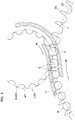
- an acceleration relaxation curve S that continuously changes the acceleration applied on the can W that is conveyed is provided in the transport portion from the filling turret 20 to the forwarding turret 4A.
- the circular conveyance path L1 of the filling turret 20 and the circular conveyance path L3A of the forwarding turret 4A are provided with a prescribed gap therebetween, in which a transport guide 7 that transports the can W along a prescribed track is provided.
- the guide surface shape of the transport guide 7 is formed along a transition curve (the acceleration relaxation curve S) that continuously changes from the pitch circle curvature of the circular conveyance path L1 of the filling turret 20 to the pitch circle curvature of the circular conveyance path L3A of the forwarding turret 4A.
- the acceleration relaxation curve S is provided in the transport portion for the can W between the filling turret 20 and the forwarding turret 4A, so that the liquid surface of the can W filled with a liquid content can be suppressed from vibrating during the transport. In this way, the problem such as spilling and foaming of the content during the transport of the can between the filling turret 20 and the forwarding turret 4A can be solved.
- transport along an acceleration relaxation curve for the same purpose can be carried out in the transport portions between the forwarding turret 4A and the forwarding turret 4B and between the forwarding turret 4B and the seamer 3, and the same advantageous effect can be obtained.
- the can filling/seaming device 1 (1A) when the can filling/seaming device 1 (1A) according to the embodiments of the present invention fills a can with a liquid content and seals the can with a lid by double-seaming, the filler 2 and the seamer 3 are coupled by the forwarding turret 4 (4A, 4B), so that use of a linear intermediate conveyance path or a special driving device for timing adjustment may be abolished, which can reduce the installation cost and the installation area.
- the acceleration (curvature) is limited at the forwarding turret 4 so that the content filled in the can does not spill from the can, transport in, for example, the transport portion from the filling turret 20 to the forwarding turret 4 (4A, 4B) is carried out along the acceleration relaxation curve, and therefore the installation area can be reduced while keeping high filling accuracy.
- the forwarding turret 4 (4A, 4B) may be provided with the lid supply part 40 or the liquid nitrogen filling part 41, and therefore the device may be provided in a compact form.
Landscapes
- Engineering & Computer Science (AREA)
- Mechanical Engineering (AREA)
- Filling Of Jars Or Cans And Processes For Cleaning And Sealing Jars (AREA)
- Closing Of Containers (AREA)
Abstract
Description
- The present invention relates to a can filling/seaming device and a can filling/seaming method for filling a can with a content and seaming a lid to a can.
- A conventional filling/seaming device includes a rotary filling machine (filler) that successively fills a can of a metal material with a liquid content such as a beverage, and a seaming machine (seamer) that successively seals a lid (metal lid) to a flange part of the filled can by seaming. A filler generally used has a plurality of holding parts (pockets) provided at the circular outer circumference of a rotating filling turret to receive and hold a can, and a filling nozzle that moves in synchronization with each of the holding parts is provided above the holding part. Successively supplied cans are sequentially held by the filling turret of the filler and then filled with a prescribed amount of liquid content from the respective filling nozzles while being conveyed by the rotation of the filling turret. The filled cans once removed from the filling turret are transported to a feeding conveyer or a hook-up conveyer and conveyed to the seamer. The seamer sequentially supplies lids to the flange parts of the filled cans supplied from the feed conveyer or the hook-up conveyer, and the flange parts of the cans and the curled parts of the lids are joined by double-seaming by roll processing, so that the lids are attached and sealed to the cans (see PTL 1).
- [PTL1] Japanese Patent Application Publication No.
2006-36266 - The filling/seaming devices are designed in various forms for different uses, and particularly when a can filled with a liquid content is sealed with a lid by seaming, it is inevitable to take precautions to prevent the content from spilling from the can in a conveyance path between the filling of the content and the seaming with the lid.
- Therefore, the conventional filling/seaming device described above has a relatively long linear intermediate conveyance path by a feeding conveyer or a hook-up conveyer between the filler and the seamer, so that the can filled with the content is not subject to high acceleration or centrifugal force during the conveyance in the path.
- However, in the conventional filling/seaming device, the presence of the linear intermediate conveyance path necessitates a certain distance to be secured between the filler and the seamer, which prevents these elements from being integrated into a compact arrangement. Positional adjustment is necessary between the carrying-out position of the filler and the receiving position of the linear intermediate conveyance path, and timing adjustment is necessary for transport from the filler to the intermediate conveyance path, which may complicate installation works and prolong the number of days for the device to be set up for operation. In daily use, the timing may be deviated because of the expansion of a conveyer chain for example, and periodic inspection and adjustment should be carried out.
Furthermore, if a special driving device is employed to alleviate the timing adjustment between the filler and the seamer, the cost increase may be inevitable. - The present invention is for example directed to a solution to such problems. More specifically, an object of the invention is to allow the filler and the seamer to be integrated in a compact arrangement in a can filling/seaming device and a can filling/seaming method for filling a can with a liquid content and seaming a lid, another object is to simplify installation works and reduce the number of days for the device to be set up for operation by eliminating the necessity of positional adjustment and timing adjustment during transport from the filler to the intermediate conveyance path and from the intermediate conveyance path to the seamer, yet another object is to reduce works related to timing deviation inspection and timing adjustment in daily use, and a still further object is to reduce the manufacturing cost by eliminating the necessity of using a special driving device for timing adjustment.
- In order to achieve the objects, a can filling/seaming device and a can filling/seaming method according to the present invention includes the following features.
- The can filling/seaming device includes a filler that fills a can with a liquid content while conveying the can by rotation of a filling turret, a seamer that attaches a lid to the can filled with the content by double-seaming, and a forwarding turret provided between a carrying-out position of the filling turret and a carrying-in position to the seamer to circularly convey the can filled with the content, wherein a lid supply part is provided on the forwarding turret.
- The can filling/seaming method includes filling a can with a liquid content while conveying the can along a circular conveyance path of a filling turret, transporting the can filled with the content from the filling turret to a forwarding turret and supplying the can with a lid while conveying the can along a circular conveyance path of the forwarding turret, and transporting the can supplied with the lid from the forwarding turret to a seamer and attaching the lid to the can by double-seaming while conveying the can along a circular conveyance path of the seamer.
- According to the present invention including such features, when a can is filled with a liquid content and seamed with a lid, a filler that fills the can with the content and the seamer that seams the lid to the can may be integrated through a forwarding turret in a compact arrangement, so that the installation area can be reduced. During the process, acceleration (curvature) is limited at the forwarding turret so that the content filled in the can does not spill from the can, and therefore the installation area can be reduced while keeping high filling accuracy.
- Positional adjustment and timing adjustment during transport from the filler to the forwarding turret or from the forwarding turret to the seamer can be abolished, so that installation works can be simplified and the number of days for the device to be set up for operation can be reduced. In daily use, works related to timing deviation inspection or timing adjustment can be reduced, and use of a special driving device for timing adjustment is not necessary, which can lower the manufacturing cost.
-
- [
Fig. 1 ]
Fig. 1 is a view for illustrating a can filling/seaming device according to one embodiment of the present invention. - [
Fig. 2 ]
Fig. 2 is a view for illustrating a can filling/seaming device according to another embodiment of the present invention. - [
Fig. 3 ]
Fig. 3 is a view for illustrating a transport portion between turrets in a can filling/seaming device according to an embodiment of the invention. - [
Fig. 4 ]
Fig. 4 is a reference view of a can filled with a content. - Now, embodiments of the present invention will be described in conjunction with the accompanying drawings. In
Fig. 1 , a can filling/seaming device 1 according to an embodiment of the present invention includes afiller 2, aseamer 3, and aforwarding turret 4.
The can W to be described herein is a can having a flange part at the open end, and W1 designates an empty can, W2 designates a can that is being filled with a liquid content such as a beverage or is already filled with the content, and W3 designates a can sealed with a lid by double-seaming in the drawings. - The
filler 2 includes a fillingturret 20 and fills a can W with a liquid content while conveying the can W by rotation of thefilling turret 20. The fillingturret 20 includes a plurality ofpockets 2P that hold cans W at its circular outer circumference, and thepockets 2P are arranged at a set conveyance pitch P1 in a circular conveyance path L1 with a pitch diameter D1. A filling nozzle (not shown) that moves in synchronization with each of thepockets 2P is provided above thepocket 2P, and the filling nozzle fills the can W with a liquid content between the carrying-inposition 20A and the carrying-outposition 20B of thefilling turret 20. - The can W (empty can W1) is supplied to the
filler 2 via an appropriate carrying-in path Lin from a rinser that cleans the cans W. As shown, during the process, a carrying-inturret 22 that receives and delivers the cans W to thepockets 2P of the fillingturret 20 or a rinser turret (not shown) that cleans the cans W may be additionally provided to the carrying-inturret 22. - The
seamer 3 attaches a lid to the flange part of the can filled with the content, by double-seaming by roll processing, and while a can W, on which a lid is placed, is conveyed in a circular conveyance path L2 from a carrying-inposition 3A to a carrying-outposition 3B, the flange part of the can and the curled part of the lid are subjected to double-seaming by roll processing, so that the can W is sealed. A pitch diameter D2 and a conveyance pitch P2 are set as appropriate in the circular conveyance path L2 of theseamer 3. - The can W carried out from the
seamer 3 is carried outside the device via an appropriate carrying-out path Lout. In the path, if necessary, adischarging turret 30 that receives and forwards the can W discharged from theseamer 3 while rotating in the direction of the shown arrow may be provided, or aninspector turret 31 that carries out various kinds of inspection including inspection about a filling amount with respect to the can W discharged from the dischargingturret 30 may be provided. - As for the
forwarding turret 4, twoforwarding turrets position 20B of the fillingturret 20 and the carrying-inposition 3A of theseamer 3 and circularly convey the can W filled with the content, andpockets 4P are provided at respective conveyance pitches P3A and P3B in the circular conveyance paths L3A and L3B with respective pitch diameters D3A and D3B. Note that while the pitch diameters D3A and D3B of theforwarding turrets - The forwarding turret 4B between the
forwarding turrets lid supply part 40 in the circular conveyance path L3B. Thelid supply part 40 may be a lid supply device directly provided in the circular conveyance path L3B or may be provided on an additional lid supply turret provided in the carrying-inposition 3A to theseamer 3 in the circular conveyance path L3B. The forwardingturret 4B may include, if necessary, a liquidnitrogen filling part 41 provided in the circular conveyance path L3B to fill the can W with liquid nitrogen so that the can is kept under positive pressure and reduced in the thickness. - Note that while one
forwarding turret 4 may be provided, if two of them are provided as shown inFig. 1 , thefirst forwarding turret 4A may be dedicated to conveyance of the cans W, so that the filling nozzle of thefiller 2 needs only to avoid the can W in the carrying-outposition 20B of thefilling turret 20. As a result, the filling nozzle may be set in a low level, the rotation angle of thefiller 2 allocated for filling may be increased, and thefiller 2 may be reduced in size. - In
such forwarding turrets position 20B of thefilling turret 20 to theforwarding turrets lid supply part 40 and are transported to theseamer 3. - The cans W filled with the content and transported to the
forwarding turrets Fig. 4 , an allowable acceleration amax during the process is represented by amax = (2h/D) × G where h is the headspace height of the can W filled with the content, D is the diameter of the can, and G is the gravitational acceleration, and the pitch diameters D3A and D3B and conveyance pitches P3A and P3B of theforwarding turrets forwarding turrets - In the filling/
seaming device 1, it is preferable that the conveyance pitches P1, P2, P3A, and P3B of thefilling turret 20 of thefiller 2, theseamer 3, and theforwarding turrets filling turret 20 and the conveyance pitches (pocket pitches) P3A and P3B of theforwarding turrets filling turret 20 to the forwardingturrets - An example of the specifications of the filling/
seaming device 1 is given in Table 1. Here, the production capacity is 600 CPM (Cans Per Minute i.e. production per minute), the conveyance pitches P1, P2, P3A, and P3B are all 31π (97.4 mm), and the conveyance speed is constant at 0.97 m/s. In this example, the centrifugal acceleration (3.82 m/s2) of theforwarding turrets [Table 1] Number of pockets Pitch diameter (mm) Centrifugal acceleration (m/s2) Filler 50 1550 1.22 Forwarding turret 16 496 3.82 Seamer 6 186 10.20 - Note that there is another typical can having a diameter (body diameter) D of 53 mm which is slightly smaller than the diameter of the above described can, and the can normally has a headspace height h of 15 mm, so that amax = 2 × 15/53 × 9.81 = 5.55 m/s2, which is within the allowable range where the acceleration amax is 5.55 m/s2.
- Therefore, the centrifugal acceleration (amax) of the
forwarding turrets - In the filling/seaming
device 1, thefiller 2 and theseamer 3 are coupled by the forwardingturrets filler 2 and theseamer 3 may be integrated in a compact arrangement through the forwardingturrets filler 2, theseamer 3, and theforwarding turrets common frame 10. When the filling/seamingdevice 1 is produced with thecommon frame 10, works related to assembly wiring and test run adjustment in the installed state may be finished in advance, and therefore the time for installation works may be reduced. - The cans W are all turret-conveyed at accurately determined conveyance pitches from the
filler 2 to theseamer 3, so that the process is not influenced by change with time that would be caused by the expansion of a chain used in linear conveyance, and positional adjustment and timing adjustment that would otherwise be necessary in transport from thefiller 2 to theforwarding turrets turrets seamer 3 can be abolished by making the conveyance pitches P1, P2, P3A, and P3B close to one another. - Note that although not shown, only one
forwarding turret 4 may be provided and in the case, thelid supply part 40 and the liquidnitrogen filling part 41 are provided in the circular conveyance path L3. Using oneforwarding turret 4, a lid supply turret may serve both to deoxidize the headspace of the can W with a replacement gas and supply the lid, and in the case, the filling nozzle of thefiller 2 must avoid the lid supply turret positioned above the can W in the carrying-outposition 20B of the fillingturret 20. Therefore, the filling nozzle must be set in a high position, must finish filling in an early stage and then must be raised, and the rotation angle of thefiller 2 allocated for filling is reduced, so that thefiller 2 is increased in size. However, a separate lid supply turret (lid supply part 40) that carries out deoxidization and supply of the lid may be provided in the carrying-inposition 3A for the can W from the forwardingturret 4 to theseamer 3, so that the rotation angle of thefiller 2 allocated for filling can be increased. - Note that according to the embodiment, it is preferable that when the liquid content is a content sensitive to oxidization such as a tea beverage and beer, the filling/seaming device is formed in a box structure surrounded by covers entirely or partly until a lid is sealed by seaming after filling, and the inside is kept under positive pressure with an inert gas for the purpose of deoxidization or with filtered air for the purpose of preventing contamination and improving the hygiene state.
-
Fig. 2 is a view of a filling/seamingdevice 1 A according to another embodiment of the invention. The same elements as those according to the above-described embodiment are designated by the same reference characters, and their description will not be repeated. The embodiment is related to an example having both a carrying-outpath L out1 for producing a normal seam can sealed with a lid by double-seaming and adischarge path L out2 for forming a small-diameter mouth part at a can and producing a bottle can sealed with a cap (metal cap) and the like, thefiller 2 and the forwardingturret 4A out of the twoforwarding turrets capper 6 for capping a cap to the mouth part of the bottle can is provided in the conveyance path L3A of the forwardingturret 4A. - In this way, when a bottle can is filled and capped with a cap, the bottle can W filled with a content by the
filler 2 is conveyed from the forwardingturret 4A via the branching forwarding turret 5 to thecapper 6 and capped with a cap while being conveyed at thecapper 6. The bottle can W discharged from thecapper 6 is discharged outside the device through adischarge path L out2 via aninspector turret 60 that carries out various kinds of inspection including inspection about a filling amount. On the other hand, when a normal seam can is filled and sealed with a lid by double-seaming, the can is transported from the forwardingturrets seamer 3 in the conveyance path L3 of theforwarding turrets - In such filling/seaming
device 1 A, thefiller 2, theseamer 3, the forwardingturrets capper 6 and the like may be integrated in a compact arrangement, and these elements can be provided on acommon frame 10. -
Fig. 3 is a view of an exemplary configuration of a transport portion between turrets in a can filling/seaming device according to an embodiment of the invention. When a can is delivered and conveyed between turrets like when the can is transported from the fillingturret 20 to the forwardingturret 4A, the curvatures of the circular conveyance paths of one turret and the other turret are inverted, so that acceleration change applied on the can is infinite. Therefore, a liquid-filled can conveyed by one turret has its liquid surface inclined by centrifugal force received during the conveyance, and then when the can is transported to the other turret, the liquid surface is inclined to the opposite side, and the liquid surface vibrates and is prone to a problem such as spilling or foaming. This may be disadvantageous in transport of the can after the can is filled, particularly at the filling/seaming device that fills the can with a liquid content and seals the lid to the can by double-seaming mentioned above. Acceleration change applied on the can is infinite, so that the can that is conveyed becomes unstable in position and may interfere with, e.g., a transport guide or the pockets of the turret, which may cause a defect such as a damage and a dent on the can. - In order to address the problem, in the example shown in
Fig. 3 , an acceleration relaxation curve S that continuously changes the acceleration applied on the can W that is conveyed is provided in the transport portion from the fillingturret 20 to the forwardingturret 4A. More specifically, while the can W is transported between the fillingturret 20 havingpockets 2P formed at the conveyance pitch P1 at the outer circumference and the forwardingturret 4A having pockets 4P formed at the conveyance pitch P3A at the outer circumference, the circular conveyance path L1 of the fillingturret 20 and the circular conveyance path L3A of the forwardingturret 4A are provided with a prescribed gap therebetween, in which a transport guide 7 that transports the can W along a prescribed track is provided. The guide surface shape of the transport guide 7 is formed along a transition curve (the acceleration relaxation curve S) that continuously changes from the pitch circle curvature of the circular conveyance path L1 of the fillingturret 20 to the pitch circle curvature of the circular conveyance path L3A of the forwardingturret 4A. - The acceleration relaxation curve S is provided in the transport portion for the can W between the filling
turret 20 and the forwardingturret 4A, so that the liquid surface of the can W filled with a liquid content can be suppressed from vibrating during the transport. In this way, the problem such as spilling and foaming of the content during the transport of the can between the fillingturret 20 and the forwardingturret 4A can be solved. Note that while the transport portion between the fillingturret 20 and the forwardingturret 4A has been described here, transport along an acceleration relaxation curve for the same purpose can be carried out in the transport portions between the forwardingturret 4A and the forwardingturret 4B and between the forwardingturret 4B and theseamer 3, and the same advantageous effect can be obtained. - As in the foregoing, when the can filling/seaming device 1 (1A) according to the embodiments of the present invention fills a can with a liquid content and seals the can with a lid by double-seaming, the
filler 2 and theseamer 3 are coupled by the forwarding turret 4 (4A, 4B), so that use of a linear intermediate conveyance path or a special driving device for timing adjustment may be abolished, which can reduce the installation cost and the installation area. The acceleration (curvature) is limited at the forwardingturret 4 so that the content filled in the can does not spill from the can, transport in, for example, the transport portion from the fillingturret 20 to the forwarding turret 4 (4A, 4B) is carried out along the acceleration relaxation curve, and therefore the installation area can be reduced while keeping high filling accuracy. The forwarding turret 4 (4A, 4B) may be provided with thelid supply part 40 or the liquidnitrogen filling part 41, and therefore the device may be provided in a compact form. - As in the foregoing, while the embodiments of the present invention have been described in detail with reference to the accompanying drawings, the specific configurations of the embodiments should not be construed as limiting, design changes and the like without departing from the gist of the invention are covered by the invention. The embodiments described above may have two or more of their features combined between each other unless their purposes, configurations and the like are contradictory to one another or a problem arises in doing so. In particular, the example shown in
Fig. 3 may be employed for all the transport portions among turrets according to the embodiments shown inFig. 1 and -
Fig. 2 . -
- 1, 1A Filling/seaming device
- 2 Filler
- 20 Filling turret
- 20A Carrying-in position
- 20B Carrying-out position
- 22 Carrying-in turret
- 3 Seamer
- 3A Carrying-in position
- 3B Carrying-out position
- 30 Discharging turret
- 31, 60 Inspector turret
- 4 (4A, 4B) Forwarding turret
- 40 Lid supply part
- 41 Liquid nitrogen filling part
- 5 Branching forwarding turret
- 6 Capper
- 7 Transport guide
- 10 Common frame
- W Can
- L1, L2, L3 (L3A, L3B) Circular conveyance path
- Lin Carrying-in path
- Lout,
L out1,L out2 Carrying-out path - 2P, 4P Pocket
- S Acceleration relaxation curve
Claims (10)
- A can filling/seaming device (1, 1 A), comprising:a filler (2) that fills a can (W) with a liquid content while conveying the can (2) by rotation of a filling turret (20);a seamer (3) that attaches a lid to the can (W) filled with the content by double-seaming; anda forwarding turret (4, 4A, 4B) provided between a carrying-out position (20B) of the filling turret (20) and a carrying-in position (3A) to said seamer (3) to circularly convey the can (W) filled with the content,wherein a lid supply part (40) is provided on the forwarding turret (4, 4A, 4B).
- The can filling/seaming device (1, 1 A) according to claim 1, wherein acceleration applied on the can (W) conveyed by the forwarding turret (4, 4A, 4B) is set less than acceleration amax defined by the expression amax = (2h/D) × G,
where h is a headspace height of the can (W), D is a diameter (body diameter) of the can (W), and G is gravitational acceleration. - The can filling/seaming device (1, 1 A) according to claim 1 or 2, wherein a conveyance pitch (P1, P3A, P3B) is set for the filling turret (20) and the forwarding turret (4, 4A, 4B) within such a range that pocket pass is enabled during transport from the filling turret (20) to the forwarding turret (4, 4A, 4B).
- The can filling/seaming device (1, 1 A) according to claim 1 or 2, wherein a transport guide (7) is provided at a transport portion from the filling turret (20) to the forwarding turret (4, 4A, 4B) and/or a transport potion from the forwarding turret (4, 4A, 4B) to the seamer (3), and
the transport guide (7) has a guide surface shape formed along an acceleration relaxation curve that continuously changes acceleration applied on the can (W) that is conveyed. - The can filling/seaming device (1, 1 A) according to any one of claims 1 to 4, wherein a branching forwarding turret (5) is provided in a conveyance path (L3, L3A, L3B) of the forwarding turret (4, 4A, 4B), the branching forwarding turret (5) branching the conveyance path (L3, L3A, L3B) to a capper (6) that caps a cap to a mouth part of a bottle can.
- The can filling/seaming device (1, 1 A) according to any one of claims 1 to 5, wherein the filler (2), the seamer (3), and the forwarding turret (4, 4A, 4B) are placed on a common frame (10).
- A can filling/seaming method, comprising:filling a can (W) with a liquid content while conveying the can (W) along a circular conveyance path (L1) of a filling turret (20);transporting the can (W) filled with the content from the filling turret (20) to a forwarding turret (4, 4A, 4B) and supplying the can (W) with a lid while conveying the can (W) along a circular conveyance path (L3, L3A, L3B) of the forwarding turret (4, 4A, 4B); andtransporting the can (W) supplied with the lid from the forwarding turret (4, 4A, 4B) to a seamer (3) and attaching the lid to the can (W) by double-seaming while conveying the can (W) along a circular conveyance path(L2) of the seamer (3).
- The can filling/seaming method according to claim 7, wherein acceleration applied on the can (W) conveyed by the forwarding turret (4, 4A, 4B) is less than acceleration defined by amax = (2h/D) × G, where h is a headspace height of the can (W) filled with the content, D is a diameter of the can (W), and G is gravitational acceleration.
- The can filling/seaming method according to claim 7 or 8, wherein transport from the filling turret (20) to the forwarding turret (4, 4A, 4B) and/or transport from the forwarding turret (4, 4A, 4B) to the seamer (3) is carried out along an acceleration relaxation curve that continuously changes acceleration applied on the can (W) that is conveyed.
- The can filling/seaming method according to any one of claim 7 to 9, wherein the conveyance path (L3, L3A, L3B) of the forwarding turret (4, 4A, 4B) branches to a capper (6) that caps a cap to a mouth part of a bottle can.
Applications Claiming Priority (2)
| Application Number | Priority Date | Filing Date | Title |
|---|---|---|---|
| JP2015006268A JP6716858B2 (en) | 2015-01-15 | 2015-01-15 | Filling and winding device and filling and winding method for can body |
| PCT/JP2015/085207 WO2016114060A1 (en) | 2015-01-15 | 2015-12-16 | Can filling/seaming device and can filling/seaming method |
Publications (3)
| Publication Number | Publication Date |
|---|---|
| EP3246258A1 true EP3246258A1 (en) | 2017-11-22 |
| EP3246258A4 EP3246258A4 (en) | 2018-10-17 |
| EP3246258B1 EP3246258B1 (en) | 2022-03-09 |
Family
ID=56405615
Family Applications (1)
| Application Number | Title | Priority Date | Filing Date |
|---|---|---|---|
| EP15878011.4A Active EP3246258B1 (en) | 2015-01-15 | 2015-12-16 | Can filling/seaming device and can filling/seaming method |
Country Status (5)
| Country | Link |
|---|---|
| US (1) | US10987719B2 (en) |
| EP (1) | EP3246258B1 (en) |
| JP (1) | JP6716858B2 (en) |
| CN (1) | CN107207104B (en) |
| WO (1) | WO2016114060A1 (en) |
Cited By (3)
| Publication number | Priority date | Publication date | Assignee | Title |
|---|---|---|---|---|
| EP3640198A1 (en) * | 2018-10-18 | 2020-04-22 | KRONES Aktiengesellschaft | Filling machine and method for handling cans or similar containers in a filling machine |
| WO2020164953A1 (en) * | 2019-02-15 | 2020-08-20 | Khs Gmbh | Container-handling apparatus with a transportation element |
| DE102021127638A1 (en) | 2021-10-25 | 2023-04-27 | Khs Gmbh | Beverage can filling system and method for forming filled beverage cans |
Families Citing this family (10)
| Publication number | Priority date | Publication date | Assignee | Title |
|---|---|---|---|---|
| US10591421B1 (en) * | 2014-02-25 | 2020-03-17 | Khs Gmbh | Beverage bottle handling device for handling beverage bottles and similar containers in a beverage bottling or container filling plant |
| JP6424511B2 (en) * | 2014-08-08 | 2018-11-21 | 東洋製罐株式会社 | Method of conveying articles and apparatus therefor |
| JP6693822B2 (en) * | 2016-06-30 | 2020-05-13 | 株式会社吉野工業所 | Container manufacturing method by liquid blow molding |
| JP6735651B2 (en) * | 2016-10-20 | 2020-08-05 | ユニバーサル製缶株式会社 | Bottle can manufacturing method |
| IT201700090958A1 (en) | 2017-08-07 | 2019-02-07 | Pe Labellers Spa | CONTAINER LABELING MACHINE. |
| DE102018208956A1 (en) * | 2018-06-06 | 2019-12-12 | Bausch + Ströbel Maschinenfabrik Ilshofen GmbH + Co. KG | turnout device |
| DE102019117377A1 (en) * | 2019-06-27 | 2020-12-31 | Khs Gmbh | Device and method for transporting containers |
| EP4119254B1 (en) * | 2020-03-13 | 2025-12-24 | Toyo Seikan Group Engineering Co., Ltd. | Container member supply device |
| ES2944183A1 (en) | 2021-12-17 | 2023-06-19 | Velategui Ignacio Escagedo | ELECTRIC ARC WELDING EQUIPMENT (Machine-translation by Google Translate, not legally binding) |
| CN116281063B (en) * | 2023-05-18 | 2023-08-04 | 四川省丹丹郫县豆瓣集团股份有限公司 | Automatic sequencing device for thick broad-bean sauce production line |
Family Cites Families (30)
| Publication number | Priority date | Publication date | Assignee | Title |
|---|---|---|---|---|
| DE1432416A1 (en) | 1964-06-05 | 1968-11-28 | Seitz Werke Gmbh | Process for placing the sealing lid on the filled cans in filling machines and for carrying out the process suitable filling machine |
| US3415037A (en) * | 1965-11-12 | 1968-12-10 | Pneumatic Scale Corp | Closure feeding and transferring device |
| JPS4947328Y1 (en) * | 1967-08-15 | 1974-12-25 | ||
| JPS5747169B2 (en) | 1972-09-07 | 1982-10-07 | ||
| JPS5524933Y2 (en) * | 1975-08-30 | 1980-06-14 | ||
| JPS52125541U (en) * | 1976-03-19 | 1977-09-24 | ||
| JPS5936672B2 (en) | 1976-04-13 | 1984-09-05 | 松下電器産業株式会社 | Adhesion method |
| DE2849741A1 (en) * | 1978-11-16 | 1980-05-29 | Seitz Werke Gmbh | DEVICE FOR CONTROLLING A LOCKING ORGAN FOR VESSEL SEALING MACHINES OF A CONTINUOUS DESIGN |
| DE3141364C2 (en) * | 1981-10-17 | 1984-12-20 | Krones Ag Hermann Kronseder Maschinenfabrik, 8402 Neutraubling | Device for distributing upright vessels |
| DE3337425A1 (en) | 1983-10-14 | 1985-04-25 | Rheinmetall GmbH, 4000 Düsseldorf | Locking device on an automatic gun, especially a machine gun |
| JPS60101496U (en) * | 1983-12-15 | 1985-07-10 | 三菱重工業株式会社 | Filling and capping device |
| IT1234085B (en) * | 1989-05-25 | 1992-04-29 | Azionaria Costruzioni Acma Spa | EQUIPMENT TO POSITION IN THE CORRECT WAY OF THE DISPENSERS TO BE APPLIED TO CONTAINERS |
| DE3927911A1 (en) | 1989-08-24 | 1991-02-28 | Alfill Getraenketechnik | METHOD AND DEVICE FOR FILLING AND SEALING CAN |
| DE8916109U1 (en) | 1989-08-24 | 1993-10-07 | Alfill Getränketechnik GmbH, 22309 Hamburg | Device for filling and closing cans |
| CH684404A5 (en) | 1991-11-27 | 1994-09-15 | Ferrum Ag | Device for feeding containers to a closing device. |
| JPH09142649A (en) * | 1995-11-17 | 1997-06-03 | Toyo Seikan Kaisha Ltd | Container feeder for filler |
| US6213309B1 (en) | 1999-04-30 | 2001-04-10 | B & H Manufacturing Company, Inc. | Turret feed control apparatus for sorting and distributing articles in a process system |
| JP3829578B2 (en) * | 2000-04-11 | 2006-10-04 | 東洋製罐株式会社 | Filling equipment |
| JP3651367B2 (en) * | 2000-07-11 | 2005-05-25 | 東洋製罐株式会社 | Canned food manufacturing method and apparatus |
| JP3991571B2 (en) * | 2000-10-02 | 2007-10-17 | 東洋製罐株式会社 | Aseptic filling negative pressure can manufacturing method and apparatus |
| JP4761636B2 (en) * | 2001-03-28 | 2011-08-31 | 日本クラウンコルク株式会社 | Capping device |
| US6915553B2 (en) * | 2003-02-19 | 2005-07-12 | Rexam Beverage Can Company | Seaming apparatus and method for cans |
| JP4420185B2 (en) * | 2003-09-02 | 2010-02-24 | 東洋製罐株式会社 | Container headspace processing method and apparatus |
| JP4252425B2 (en) * | 2003-11-12 | 2009-04-08 | 東洋食品機械株式会社 | Container lid clamping device and its conveying device |
| JP4758623B2 (en) | 2004-07-27 | 2011-08-31 | 大和製罐株式会社 | production equipment |
| JP2006151483A (en) * | 2004-11-30 | 2006-06-15 | Toyo Food Equipment Co Ltd | Crown cap applicator |
| JP4942346B2 (en) * | 2006-01-17 | 2012-05-30 | 大和製罐株式会社 | Capping device and capping method |
| US7568573B2 (en) * | 2007-09-21 | 2009-08-04 | Belvac Production Machinery, Inc. | High speed selective container sorter |
| DE102008052768A1 (en) | 2008-10-22 | 2010-04-29 | Krones Ag | Device for transporting containers |
| DE102012000758A1 (en) * | 2012-01-18 | 2013-07-18 | Khs Gmbh | Plant and method for filling containers |
-
2015
- 2015-01-15 JP JP2015006268A patent/JP6716858B2/en active Active
- 2015-12-16 WO PCT/JP2015/085207 patent/WO2016114060A1/en not_active Ceased
- 2015-12-16 EP EP15878011.4A patent/EP3246258B1/en active Active
- 2015-12-16 CN CN201580073570.6A patent/CN107207104B/en active Active
- 2015-12-16 US US15/538,378 patent/US10987719B2/en active Active
Cited By (6)
| Publication number | Priority date | Publication date | Assignee | Title |
|---|---|---|---|---|
| EP3640198A1 (en) * | 2018-10-18 | 2020-04-22 | KRONES Aktiengesellschaft | Filling machine and method for handling cans or similar containers in a filling machine |
| CN111071771A (en) * | 2018-10-18 | 2020-04-28 | 克朗斯股份公司 | Method and filling machine for handling cans or such containers in a filling machine |
| WO2020164953A1 (en) * | 2019-02-15 | 2020-08-20 | Khs Gmbh | Container-handling apparatus with a transportation element |
| US11912557B2 (en) | 2019-02-15 | 2024-02-27 | Khs Gmbh | Container-handling apparatus with a transportation element |
| DE102021127638A1 (en) | 2021-10-25 | 2023-04-27 | Khs Gmbh | Beverage can filling system and method for forming filled beverage cans |
| WO2023072667A1 (en) | 2021-10-25 | 2023-05-04 | Khs Gmbh | Beverage can filling plant and method for forming filled beverage cans |
Also Published As
| Publication number | Publication date |
|---|---|
| EP3246258B1 (en) | 2022-03-09 |
| CN107207104B (en) | 2020-02-28 |
| WO2016114060A1 (en) | 2016-07-21 |
| CN107207104A (en) | 2017-09-26 |
| US10987719B2 (en) | 2021-04-27 |
| US20170348757A1 (en) | 2017-12-07 |
| JP2016131979A (en) | 2016-07-25 |
| JP6716858B2 (en) | 2020-07-01 |
| EP3246258A4 (en) | 2018-10-17 |
Similar Documents
| Publication | Publication Date | Title |
|---|---|---|
| EP3246258B1 (en) | Can filling/seaming device and can filling/seaming method | |
| JP6009001B2 (en) | Container filling and sealing device | |
| JP6424511B2 (en) | Method of conveying articles and apparatus therefor | |
| US6701692B1 (en) | Device for closing plastic bottles | |
| CN115279511B (en) | Container member supply device | |
| US11912557B2 (en) | Container-handling apparatus with a transportation element | |
| US4721200A (en) | Can filling system to prevent damage to cans | |
| US12509340B2 (en) | Container feeding system for transporting container, as well as processing device and method for transporting container | |
| JP2019038586A (en) | Transport mechanism | |
| EP2133292B1 (en) | Apparatus for unscrambling and aligning bulk plastic containers | |
| CN108137246A (en) | Intermediate storage mean and the method for intermediate storage | |
| US4099621A (en) | Conveying and reject apparatus for upright standing bottles | |
| JP4252424B2 (en) | Container filling lid clamping device | |
| GB2204307A (en) | Process and apparatus for transporting containers | |
| WO2024257459A1 (en) | Closed-bottom cylindrical body processing device | |
| US4664159A (en) | Can filling system to prevent damage to cans | |
| US3750801A (en) | Conveying device | |
| CN112978656B (en) | Device for introducing or removing containers and container treatment device | |
| JP2005145478A (en) | Seamer and transfer apparatus for container | |
| US11472635B2 (en) | Device, facility and method for ejecting products | |
| JP6636820B2 (en) | Winding device | |
| JP2004161350A (en) | Gas displacement device of capper | |
| US12275592B2 (en) | Container feed system for the transport of containers | |
| JP7244902B2 (en) | filling packaging machine | |
| JP2002193390A (en) | Rotary filling device |
Legal Events
| Date | Code | Title | Description |
|---|---|---|---|
| STAA | Information on the status of an ep patent application or granted ep patent |
Free format text: STATUS: THE INTERNATIONAL PUBLICATION HAS BEEN MADE |
|
| PUAI | Public reference made under article 153(3) epc to a published international application that has entered the european phase |
Free format text: ORIGINAL CODE: 0009012 |
|
| STAA | Information on the status of an ep patent application or granted ep patent |
Free format text: STATUS: REQUEST FOR EXAMINATION WAS MADE |
|
| 17P | Request for examination filed |
Effective date: 20170731 |
|
| AK | Designated contracting states |
Kind code of ref document: A1 Designated state(s): AL AT BE BG CH CY CZ DE DK EE ES FI FR GB GR HR HU IE IS IT LI LT LU LV MC MK MT NL NO PL PT RO RS SE SI SK SM TR |
|
| AX | Request for extension of the european patent |
Extension state: BA ME |
|
| DAV | Request for validation of the european patent (deleted) | ||
| DAX | Request for extension of the european patent (deleted) | ||
| A4 | Supplementary search report drawn up and despatched |
Effective date: 20180913 |
|
| RIC1 | Information provided on ipc code assigned before grant |
Ipc: B67B 3/02 20060101ALI20180907BHEP Ipc: B65B 7/28 20060101AFI20180907BHEP Ipc: B67B 3/06 20060101ALI20180907BHEP Ipc: B21D 51/30 20060101ALI20180907BHEP Ipc: B67C 7/00 20060101ALI20180907BHEP |
|
| STAA | Information on the status of an ep patent application or granted ep patent |
Free format text: STATUS: EXAMINATION IS IN PROGRESS |
|
| 17Q | First examination report despatched |
Effective date: 20200515 |
|
| GRAP | Despatch of communication of intention to grant a patent |
Free format text: ORIGINAL CODE: EPIDOSNIGR1 |
|
| STAA | Information on the status of an ep patent application or granted ep patent |
Free format text: STATUS: GRANT OF PATENT IS INTENDED |
|
| INTG | Intention to grant announced |
Effective date: 20211124 |
|
| GRAS | Grant fee paid |
Free format text: ORIGINAL CODE: EPIDOSNIGR3 |
|
| GRAA | (expected) grant |
Free format text: ORIGINAL CODE: 0009210 |
|
| STAA | Information on the status of an ep patent application or granted ep patent |
Free format text: STATUS: THE PATENT HAS BEEN GRANTED |
|
| AK | Designated contracting states |
Kind code of ref document: B1 Designated state(s): AL AT BE BG CH CY CZ DE DK EE ES FI FR GB GR HR HU IE IS IT LI LT LU LV MC MK MT NL NO PL PT RO RS SE SI SK SM TR |
|
| REG | Reference to a national code |
Ref country code: GB Ref legal event code: FG4D |
|
| REG | Reference to a national code |
Ref country code: CH Ref legal event code: EP Ref country code: AT Ref legal event code: REF Ref document number: 1473970 Country of ref document: AT Kind code of ref document: T Effective date: 20220315 |
|
| REG | Reference to a national code |
Ref country code: DE Ref legal event code: R096 Ref document number: 602015077490 Country of ref document: DE |
|
| REG | Reference to a national code |
Ref country code: IE Ref legal event code: FG4D |
|
| REG | Reference to a national code |
Ref country code: LT Ref legal event code: MG9D |
|
| REG | Reference to a national code |
Ref country code: NL Ref legal event code: MP Effective date: 20220309 |
|
| PG25 | Lapsed in a contracting state [announced via postgrant information from national office to epo] |
Ref country code: SE Free format text: LAPSE BECAUSE OF FAILURE TO SUBMIT A TRANSLATION OF THE DESCRIPTION OR TO PAY THE FEE WITHIN THE PRESCRIBED TIME-LIMIT Effective date: 20220309 Ref country code: RS Free format text: LAPSE BECAUSE OF FAILURE TO SUBMIT A TRANSLATION OF THE DESCRIPTION OR TO PAY THE FEE WITHIN THE PRESCRIBED TIME-LIMIT Effective date: 20220309 Ref country code: NO Free format text: LAPSE BECAUSE OF FAILURE TO SUBMIT A TRANSLATION OF THE DESCRIPTION OR TO PAY THE FEE WITHIN THE PRESCRIBED TIME-LIMIT Effective date: 20220609 Ref country code: LT Free format text: LAPSE BECAUSE OF FAILURE TO SUBMIT A TRANSLATION OF THE DESCRIPTION OR TO PAY THE FEE WITHIN THE PRESCRIBED TIME-LIMIT Effective date: 20220309 Ref country code: HR Free format text: LAPSE BECAUSE OF FAILURE TO SUBMIT A TRANSLATION OF THE DESCRIPTION OR TO PAY THE FEE WITHIN THE PRESCRIBED TIME-LIMIT Effective date: 20220309 Ref country code: BG Free format text: LAPSE BECAUSE OF FAILURE TO SUBMIT A TRANSLATION OF THE DESCRIPTION OR TO PAY THE FEE WITHIN THE PRESCRIBED TIME-LIMIT Effective date: 20220609 |
|
| REG | Reference to a national code |
Ref country code: AT Ref legal event code: MK05 Ref document number: 1473970 Country of ref document: AT Kind code of ref document: T Effective date: 20220309 |
|
| PG25 | Lapsed in a contracting state [announced via postgrant information from national office to epo] |
Ref country code: LV Free format text: LAPSE BECAUSE OF FAILURE TO SUBMIT A TRANSLATION OF THE DESCRIPTION OR TO PAY THE FEE WITHIN THE PRESCRIBED TIME-LIMIT Effective date: 20220309 Ref country code: GR Free format text: LAPSE BECAUSE OF FAILURE TO SUBMIT A TRANSLATION OF THE DESCRIPTION OR TO PAY THE FEE WITHIN THE PRESCRIBED TIME-LIMIT Effective date: 20220610 Ref country code: FI Free format text: LAPSE BECAUSE OF FAILURE TO SUBMIT A TRANSLATION OF THE DESCRIPTION OR TO PAY THE FEE WITHIN THE PRESCRIBED TIME-LIMIT Effective date: 20220309 |
|
| PG25 | Lapsed in a contracting state [announced via postgrant information from national office to epo] |
Ref country code: NL Free format text: LAPSE BECAUSE OF FAILURE TO SUBMIT A TRANSLATION OF THE DESCRIPTION OR TO PAY THE FEE WITHIN THE PRESCRIBED TIME-LIMIT Effective date: 20220309 |
|
| PG25 | Lapsed in a contracting state [announced via postgrant information from national office to epo] |
Ref country code: SM Free format text: LAPSE BECAUSE OF FAILURE TO SUBMIT A TRANSLATION OF THE DESCRIPTION OR TO PAY THE FEE WITHIN THE PRESCRIBED TIME-LIMIT Effective date: 20220309 Ref country code: SK Free format text: LAPSE BECAUSE OF FAILURE TO SUBMIT A TRANSLATION OF THE DESCRIPTION OR TO PAY THE FEE WITHIN THE PRESCRIBED TIME-LIMIT Effective date: 20220309 Ref country code: RO Free format text: LAPSE BECAUSE OF FAILURE TO SUBMIT A TRANSLATION OF THE DESCRIPTION OR TO PAY THE FEE WITHIN THE PRESCRIBED TIME-LIMIT Effective date: 20220309 Ref country code: PT Free format text: LAPSE BECAUSE OF FAILURE TO SUBMIT A TRANSLATION OF THE DESCRIPTION OR TO PAY THE FEE WITHIN THE PRESCRIBED TIME-LIMIT Effective date: 20220711 Ref country code: ES Free format text: LAPSE BECAUSE OF FAILURE TO SUBMIT A TRANSLATION OF THE DESCRIPTION OR TO PAY THE FEE WITHIN THE PRESCRIBED TIME-LIMIT Effective date: 20220309 Ref country code: EE Free format text: LAPSE BECAUSE OF FAILURE TO SUBMIT A TRANSLATION OF THE DESCRIPTION OR TO PAY THE FEE WITHIN THE PRESCRIBED TIME-LIMIT Effective date: 20220309 Ref country code: CZ Free format text: LAPSE BECAUSE OF FAILURE TO SUBMIT A TRANSLATION OF THE DESCRIPTION OR TO PAY THE FEE WITHIN THE PRESCRIBED TIME-LIMIT Effective date: 20220309 Ref country code: AT Free format text: LAPSE BECAUSE OF FAILURE TO SUBMIT A TRANSLATION OF THE DESCRIPTION OR TO PAY THE FEE WITHIN THE PRESCRIBED TIME-LIMIT Effective date: 20220309 |
|
| PG25 | Lapsed in a contracting state [announced via postgrant information from national office to epo] |
Ref country code: PL Free format text: LAPSE BECAUSE OF FAILURE TO SUBMIT A TRANSLATION OF THE DESCRIPTION OR TO PAY THE FEE WITHIN THE PRESCRIBED TIME-LIMIT Effective date: 20220309 Ref country code: IS Free format text: LAPSE BECAUSE OF FAILURE TO SUBMIT A TRANSLATION OF THE DESCRIPTION OR TO PAY THE FEE WITHIN THE PRESCRIBED TIME-LIMIT Effective date: 20220709 Ref country code: AL Free format text: LAPSE BECAUSE OF FAILURE TO SUBMIT A TRANSLATION OF THE DESCRIPTION OR TO PAY THE FEE WITHIN THE PRESCRIBED TIME-LIMIT Effective date: 20220309 |
|
| REG | Reference to a national code |
Ref country code: DE Ref legal event code: R097 Ref document number: 602015077490 Country of ref document: DE |
|
| PLBE | No opposition filed within time limit |
Free format text: ORIGINAL CODE: 0009261 |
|
| STAA | Information on the status of an ep patent application or granted ep patent |
Free format text: STATUS: NO OPPOSITION FILED WITHIN TIME LIMIT |
|
| PG25 | Lapsed in a contracting state [announced via postgrant information from national office to epo] |
Ref country code: DK Free format text: LAPSE BECAUSE OF FAILURE TO SUBMIT A TRANSLATION OF THE DESCRIPTION OR TO PAY THE FEE WITHIN THE PRESCRIBED TIME-LIMIT Effective date: 20220309 |
|
| 26N | No opposition filed |
Effective date: 20221212 |
|
| PG25 | Lapsed in a contracting state [announced via postgrant information from national office to epo] |
Ref country code: SI Free format text: LAPSE BECAUSE OF FAILURE TO SUBMIT A TRANSLATION OF THE DESCRIPTION OR TO PAY THE FEE WITHIN THE PRESCRIBED TIME-LIMIT Effective date: 20220309 |
|
| PG25 | Lapsed in a contracting state [announced via postgrant information from national office to epo] |
Ref country code: IT Free format text: LAPSE BECAUSE OF FAILURE TO SUBMIT A TRANSLATION OF THE DESCRIPTION OR TO PAY THE FEE WITHIN THE PRESCRIBED TIME-LIMIT Effective date: 20220309 |
|
| REG | Reference to a national code |
Ref country code: CH Ref legal event code: PL |
|
| GBPC | Gb: european patent ceased through non-payment of renewal fee |
Effective date: 20221216 |
|
| REG | Reference to a national code |
Ref country code: BE Ref legal event code: MM Effective date: 20221231 |
|
| PG25 | Lapsed in a contracting state [announced via postgrant information from national office to epo] |
Ref country code: LU Free format text: LAPSE BECAUSE OF NON-PAYMENT OF DUE FEES Effective date: 20221216 |
|
| PG25 | Lapsed in a contracting state [announced via postgrant information from national office to epo] |
Ref country code: LI Free format text: LAPSE BECAUSE OF NON-PAYMENT OF DUE FEES Effective date: 20221231 Ref country code: IE Free format text: LAPSE BECAUSE OF NON-PAYMENT OF DUE FEES Effective date: 20221216 Ref country code: GB Free format text: LAPSE BECAUSE OF NON-PAYMENT OF DUE FEES Effective date: 20221216 Ref country code: CH Free format text: LAPSE BECAUSE OF NON-PAYMENT OF DUE FEES Effective date: 20221231 |
|
| PG25 | Lapsed in a contracting state [announced via postgrant information from national office to epo] |
Ref country code: BE Free format text: LAPSE BECAUSE OF NON-PAYMENT OF DUE FEES Effective date: 20221231 |
|
| PG25 | Lapsed in a contracting state [announced via postgrant information from national office to epo] |
Ref country code: HU Free format text: LAPSE BECAUSE OF FAILURE TO SUBMIT A TRANSLATION OF THE DESCRIPTION OR TO PAY THE FEE WITHIN THE PRESCRIBED TIME-LIMIT; INVALID AB INITIO Effective date: 20151216 |
|
| PG25 | Lapsed in a contracting state [announced via postgrant information from national office to epo] |
Ref country code: CY Free format text: LAPSE BECAUSE OF FAILURE TO SUBMIT A TRANSLATION OF THE DESCRIPTION OR TO PAY THE FEE WITHIN THE PRESCRIBED TIME-LIMIT Effective date: 20220309 |
|
| PG25 | Lapsed in a contracting state [announced via postgrant information from national office to epo] |
Ref country code: MK Free format text: LAPSE BECAUSE OF FAILURE TO SUBMIT A TRANSLATION OF THE DESCRIPTION OR TO PAY THE FEE WITHIN THE PRESCRIBED TIME-LIMIT Effective date: 20220309 |
|
| PG25 | Lapsed in a contracting state [announced via postgrant information from national office to epo] |
Ref country code: MC Free format text: LAPSE BECAUSE OF FAILURE TO SUBMIT A TRANSLATION OF THE DESCRIPTION OR TO PAY THE FEE WITHIN THE PRESCRIBED TIME-LIMIT Effective date: 20220309 |
|
| PG25 | Lapsed in a contracting state [announced via postgrant information from national office to epo] |
Ref country code: MC Free format text: LAPSE BECAUSE OF FAILURE TO SUBMIT A TRANSLATION OF THE DESCRIPTION OR TO PAY THE FEE WITHIN THE PRESCRIBED TIME-LIMIT Effective date: 20220309 |
|
| PG25 | Lapsed in a contracting state [announced via postgrant information from national office to epo] |
Ref country code: MT Free format text: LAPSE BECAUSE OF FAILURE TO SUBMIT A TRANSLATION OF THE DESCRIPTION OR TO PAY THE FEE WITHIN THE PRESCRIBED TIME-LIMIT Effective date: 20220309 |
|
| PG25 | Lapsed in a contracting state [announced via postgrant information from national office to epo] |
Ref country code: TR Free format text: LAPSE BECAUSE OF FAILURE TO SUBMIT A TRANSLATION OF THE DESCRIPTION OR TO PAY THE FEE WITHIN THE PRESCRIBED TIME-LIMIT Effective date: 20220309 |
|
| PGFP | Annual fee paid to national office [announced via postgrant information from national office to epo] |
Ref country code: DE Payment date: 20251211 Year of fee payment: 11 |
|
| PGFP | Annual fee paid to national office [announced via postgrant information from national office to epo] |
Ref country code: FR Payment date: 20251229 Year of fee payment: 11 |