EP3246182A1 - Pneumatic tire and method of manufacturing pneumatic tire - Google Patents
Pneumatic tire and method of manufacturing pneumatic tire Download PDFInfo
- Publication number
- EP3246182A1 EP3246182A1 EP17168373.3A EP17168373A EP3246182A1 EP 3246182 A1 EP3246182 A1 EP 3246182A1 EP 17168373 A EP17168373 A EP 17168373A EP 3246182 A1 EP3246182 A1 EP 3246182A1
- Authority
- EP
- European Patent Office
- Prior art keywords
- plate
- members
- pneumatic tire
- tread portion
- tire
- Prior art date
- Legal status (The legal status is an assumption and is not a legal conclusion. Google has not performed a legal analysis and makes no representation as to the accuracy of the status listed.)
- Granted
Links
- 238000004519 manufacturing process Methods 0.000 title claims description 21
- 239000011148 porous material Substances 0.000 claims description 8
- 238000004080 punching Methods 0.000 claims description 8
- 239000011347 resin Substances 0.000 claims description 7
- 229920005989 resin Polymers 0.000 claims description 7
- 238000003780 insertion Methods 0.000 claims description 5
- 230000037431 insertion Effects 0.000 claims description 5
- 239000004744 fabric Substances 0.000 claims description 4
- 238000000034 method Methods 0.000 claims description 4
- 238000013016 damping Methods 0.000 description 13
- 230000000694 effects Effects 0.000 description 12
- 239000000463 material Substances 0.000 description 8
- 239000004433 Thermoplastic polyurethane Substances 0.000 description 3
- 238000005192 partition Methods 0.000 description 3
- 239000007787 solid Substances 0.000 description 3
- 229920002803 thermoplastic polyurethane Polymers 0.000 description 3
- 239000011358 absorbing material Substances 0.000 description 2
- 239000011324 bead Substances 0.000 description 2
- 238000005520 cutting process Methods 0.000 description 2
- 230000006866 deterioration Effects 0.000 description 2
- 230000007257 malfunction Effects 0.000 description 2
- 239000002245 particle Substances 0.000 description 2
- 230000002093 peripheral effect Effects 0.000 description 2
- 239000004814 polyurethane Substances 0.000 description 2
- 229920005830 Polyurethane Foam Polymers 0.000 description 1
- 239000000853 adhesive Substances 0.000 description 1
- 230000002411 adverse Effects 0.000 description 1
- 239000000446 fuel Substances 0.000 description 1
- 230000010355 oscillation Effects 0.000 description 1
- 239000011496 polyurethane foam Substances 0.000 description 1
- 238000002207 thermal evaporation Methods 0.000 description 1
Images


Classifications
-
- B—PERFORMING OPERATIONS; TRANSPORTING
- B60—VEHICLES IN GENERAL
- B60C—VEHICLE TYRES; TYRE INFLATION; TYRE CHANGING; CONNECTING VALVES TO INFLATABLE ELASTIC BODIES IN GENERAL; DEVICES OR ARRANGEMENTS RELATED TO TYRES
- B60C19/00—Tyre parts or constructions not otherwise provided for
- B60C19/002—Noise damping elements provided in the tyre structure or attached thereto, e.g. in the tyre interior
-
- B—PERFORMING OPERATIONS; TRANSPORTING
- B29—WORKING OF PLASTICS; WORKING OF SUBSTANCES IN A PLASTIC STATE IN GENERAL
- B29D—PRODUCING PARTICULAR ARTICLES FROM PLASTICS OR FROM SUBSTANCES IN A PLASTIC STATE
- B29D30/00—Producing pneumatic or solid tyres or parts thereof
- B29D30/0061—Accessories, details or auxiliary operations not otherwise provided for
-
- B—PERFORMING OPERATIONS; TRANSPORTING
- B60—VEHICLES IN GENERAL
- B60C—VEHICLE TYRES; TYRE INFLATION; TYRE CHANGING; CONNECTING VALVES TO INFLATABLE ELASTIC BODIES IN GENERAL; DEVICES OR ARRANGEMENTS RELATED TO TYRES
- B60C5/00—Inflatable pneumatic tyres or inner tubes
-
- B—PERFORMING OPERATIONS; TRANSPORTING
- B29—WORKING OF PLASTICS; WORKING OF SUBSTANCES IN A PLASTIC STATE IN GENERAL
- B29D—PRODUCING PARTICULAR ARTICLES FROM PLASTICS OR FROM SUBSTANCES IN A PLASTIC STATE
- B29D30/00—Producing pneumatic or solid tyres or parts thereof
- B29D30/0061—Accessories, details or auxiliary operations not otherwise provided for
- B29D2030/0072—Attaching fasteners to tyres, e.g. patches, in order to connect devices to tyres
Definitions
- the present invention relates to a pneumatic tire which can reduce a cavity resonance noise by attaching a plate-like member to an inner surface of a tread portion, and a method of manufacturing the pneumatic tire.
- a sound called as a road noise may be generated within the vehicle.
- the road noise is one of the sound with which a tire is involved.
- a cavity resonance noise is excited in an internal portion of the tire by the oscillation, and the sound is caused within the vehicle.
- Patent Document 1 describes a pneumatic tire in which a sound control material made of a sponge material is disposed in a tire inner cavity which is surrounded by a rim and the pneumatic tire, for reducing the road noise.
- the sponge material mentioned above causes increase in the weight of a whole tire, resulting in a lowered fuel efficiency. Further, there is a problem that a cost increase is caused since a lot of sponge material is required.
- Patent Document 2 describes a pneumatic tire in which a partition wall comparting an air chamber in a circumferential direction is provided within the air chamber, which is formed between a tire inner peripheral surface and a rim outer peripheral surface, for the purpose of preventing increase in the road noise while suppressing a great cost increase.
- An equivalent length of an air column within the air chamber becomes short by comparting the air chamber in the circumferential direction by the partition wall, and it is possible to shift a resonant frequency of an air column resonance. As a result, it is possible to prevent the road noise from being increased by the air column resonance.
- Patent Document 3 describes a pneumatic tire in which an inner wall of the tire is provided with a thin elastic divider plate extending approximately in an axial direction within the tire inner cavity, for the purpose of reducing the load noise which is caused by the cavity resonance noise, while suppressing the increase of the weight.
- a sound pressure mode is changed in a whole of the tire inner cavity by the provision of the elastic divider plate within the tire inner cavity, and an in-vehicle sound level is reduced.
- the partition wall and the divider plate oscillate themselves and may increase the road noise caused by the cavity resonance noise by serving a new sound source.
- an object of the present invention is to provide a pneumatic tire which can reduce a cavity resonance noise while suppressing weight increase and cost increase, and a method of manufacturing the pneumatic tire.
- the present invention provides a pneumatic tire including two plate-like members which have a plurality of through holes formed therein, and are adhered to each other by adhesion portions at least at two positions spaced apart from each other, and a supporting member which is inserted between the two plate-like members between the adhesion portions being adjacent to each other, wherein a part of an outer surface of one of the two plate-like members is attached to an inner surface of a tread portion so that a space is formed between the outer surface of the one of the two plate-like members that are adhered and the inner surface of the tread portion.
- two plate-like members having a plurality of through holes formed therein are attached to the inner surface of the tread portion. More specifically, the two plate-like members are adhered to each other by the adhesion portions at least at two positions which are spaced apart from each other, and a part of the outer surface of one of the two plate-like members is attached to the inner surface of the tread portion so that a space is formed between the outer surface of the one of the two plate-like members and the inner surface of the tread portion.
- a plurality of through holes is formed in the two plate-like members which are in a floating state from the inner surface of the tread portion.
- the sound passes through the through hole, there are generated the viscous damping caused by the friction between the air and the inner wall surface of the through hole, and the pressure loss damping caused by the vortex generated by the passing. Therefore, the sound is damped.
- the sound within the tire passes through the through hole by attaching the plate-like member having the through holes formed therein to the inner surface of the tread portion, whereby it is possible to damp and reduce the cavity resonance noise.
- the supporting member is inserted between the two plate-like members between the adjacent adhesion portions, it is possible to prevent a situation where the plate-like member is crushed against the inner surface of the tread portion due to the centrifugal force in association with the rotation of the tire and, thereby, the through holes are closed. As a result, it is possible to damp and reduce the cavity resonance noise not only at a low speed to a middle speed, but also at a high speed.
- the adhesion portions at the two positions may be arranged along a tire circumferential direction.
- the outer surface of the one of the two plate-like members may be attached to the inner surface of the tread portion in a portion which is closer to an outer side than to the adhesion portions at the two positions.
- a space tends to be formed between the plate-like member facing to the inner surface of the tread portion among the two plate-like members and the inner surface of the tread portion, and it is possible to effectively reduce the cavity resonance noise by the through hole.
- the two plate-like members may be adhered to each other at the adhesion portions at three or more positions which are spaced apart from one another at uniform intervals, and the supporting members may be respectively inserted between the two plate-like members between the adjacent adhesion portions, and the two plate-like members may be attached to the inner surface of the tread portion over its whole periphery.
- the two plate-like members are attached to the inner surface of the tread portion over a whole periphery, it is possible to effectively reduce the cavity resonance noise by the through hole. Further, it is possible to suppress deterioration of the uniformity and the weight balance by arranging the supporting members at uniform intervals over a whole periphery in the tire circumferential direction.
- the present invention provides a method of manufacturing a pneumatic tire, the method including an adhesion step of adhering two plate-like members, which are overlapped, to each other by adhesion portions at least at two positions which are spaced apart from each other, a punching step of forming a plurality of through holes in the two plate-like members, an insertion step of inserting a supporting member between the two plate-like members between the adjacent adhesion portions, and an attachment step of attaching a part of an outer surface of one of the two plate-like members to an inner surface of a tread portion so that a space is formed between the outer surface of the one of the adhered two plate-like members and the inner surface of the tread portion.
- two plate-like members having a plurality of through holes formed therein are attached to the inner surface of the tread portion. More specifically, the two plate-like members are adhered to each other by the adhesion portions at least two positions which are spaced apart from each other, and a part of the outer surface of one of the two plate-like members is attached to the inner surface of the tread portion so that a space is formed between the outer surface of one of the adhered two plate-like members and the inner surface of the tread portion.
- a plurality of through holes is formed in the two plate-like members which are in a floating state from the inner surface of the tread portion.
- the sound passes through the through hole, there are generated the viscous damping caused by the friction between the air and the inner wall surface of the through hole, and the pressure loss damping caused by the vortex generated by the passing. Therefore, the sound is damped.
- the sound within the tire passes through the through hole by attaching the plate-like member having the through holes formed therein to the inner surface of the tread portion, whereby it is possible to damp and reduce the cavity resonance noise. Further, since it is not necessary to provide a lot of noise absorbing material and sound control material such as sponge material, it is possible to suppress increase of the weight and increase of the cost.
- the supporting member is inserted between the two plate-like members between the adjacent adhesion portions, it is possible to prevent a situation where the plate-like members is crushed against the inner surface of the tread portion due to the centrifugal force in association with the rotation of the tire and, thereby, the through holes are closed. As a result, it is possible to damp and reduce the cavity resonance noise not only at a low speed to a middle speed, but also at a high speed.
- the adhesion step may be carried out before the punching step.
- the through holes can be formed simultaneously in the two plate-like members which are overlapped, it is possible to easily form a plurality of through holes.
- the two plate-like members may be two long plate-like members which are supplied continuously, the two plate-like members may be adhered to each other by the adhesion portions at three or more positions which are spaced apart from one another in a longitudinal direction, in the adhesion step, the supporting members may be inserted respectively between the two plate-like members between the adhesion portions which are adjacent to each other, in the insertion step, and the adhered two plate-like members may be attached to the inner surface of the tread portion over its whole periphery, in the attachment step.
- the two plate-like members are attached to the inner surface of the tread portion over a whole periphery, it is possible to effectively reduce the cavity resonance noise by the through hole. Further, it is possible to suppress deterioration of the uniformity and the weight balance by arranging the supporting members at uniform intervals over a whole periphery in the tire circumferential direction.
- FIG. 1 is a perspective view showing an example of a pneumatic tire.
- FIG. 2A is an example of a tire meridian cross-sectional view of the pneumatic tire.
- FIG. 2B is an example of a cross-sectional view in a tire circumferential direction of the pneumatic tire.
- reference symbol H denotes a tire cross-sectional height.
- the tire cross-sectional height H is a height from a nominal rim diameter to a tread surface in a state of being filled with a pneumatic pressure prescribed by JATMA, in a tire meridian cross section.
- a pneumatic tire 1 is provided with a pair of annular bead portions 11, side wall portions 12 which extend to outer sides in a tire diametrical direction from each of the bead portions 11, and a tread portion 13 which is connected to outer ends in the tire diametrical direction of each of the side wall portions 12, as shown in FIGS. 1 and 2A .
- the pneumatic tire 1 is provided with two plate-like members 21 and 22 which are attached to an inner surface 13a of the tread portion.
- the two plate-like members 21 and 22 are attached to the inner surface 13a of the tread portion by two mounting portions 21a and 21b which are arranged so as to be spaced apart from each other in a tire circumferential direction CD.
- the two plate-like members 21 and 22 are adhered to each other by adhesion portions 2a and 2b at least two positions which are spaced apart from each other.
- the adhesion portions 2a and 2b at two positions are arranged along a tire circumferential direction CD.
- the adhesion portions 2a and 2b are adhere by thermal deposition or ultrasonic adhesion.
- the adhesion portions 2a and 2b extend in a tire width direction WD of the plate-like members 21 and 22.
- a support member 3 is inserted between the two plate-like members 21 and 22 between the adhesion portion 2a and the adhesion portion 2b which are adjacent to each other.
- the supporting member 3 according to the present embodiment is formed into a tubular shape which extends along the tire width direction WD. Details of the supporting member 3 will be described later.
- a space 20 is formed between an outer surface of the plate-like member 21 facing to the inner surface 13a of the tread portion among two adhered plate-like members 21 and 22 and the inner surface 13a of the tread portion.
- a part of the outer surface of the plate-like member 21 is in non-contact with the inner surface 13a of the tread portion.
- the outer surface of the plate-like member 21 is fixed to the inner surface 13a of the tread portion by the mounting portions 21a and 21b.
- the outer surface of the plate-like member 21 positioned in the outer side in the tire diametrical direction of the supporting member 3 is in contact with the inner surface 13a of the tread portion, however, is not fixed to the inner surface 13a of the tread portion.
- the space 20 is an area which is surrounded by the outer surface of the plate-like member 21 and the inner surface 13a of the tread portion, between the adjacent mounting portions 21a and 21b.
- a plurality of through holes 4 is formed in the two plate-like members 21 and 22.
- the through holes 4 are formed in a whole surface of the two plate-like members 21 and 22. There exist the through holes 4 which are in contact with the supporting member 3, and the through holes 4 which are formed toward the space 20 without being in contact with the supporting member 3.
- the through holes 4 are arranged at the positions having the greater particle speed, the cavity resonance noise can be effectively damped. Further, since the air flow is added to the speed, the through holes 4 are preferably arranged in the place having the air flow, in the rotating tire.
- FIG. 3 is an enlarged cross-sectional view showing the plate-like members 21 and 22 having the through holes 4 formed therein in an enlarged manner (in this case, the supporting member 3 is not shown).
- the air flow within the tire is shown by arrows.
- Within the tire there exist an air flow Sr in the tire diametrical direction which is generated by deformation of the tire caused by the ground on the road surface, and an air flow Sc in the circumferential direction CD which is generated by restoration of the deformation.
- the sound transmitted in the tire circumferential direction CD and the air flow Sc in the tire circumferential direction CD pass through the through holes 4 by attaching a part of the outer surface of the plate-like member 21 to the inner surface 13a of the tread portion so that the space 20 is formed between the outer surface of the plate-like member 21 and the inner surface 13a of the tread portion, it is possible to effectively reduce the cavity resonance noise.
- the plate-like members 21 and 22 having the through holes 4 therein are attached to the inner surface 13a of the tread portion.
- the supporting member 3 is inserted between the two plate-like members 21 and 22.
- the plate-like members 21 and 22 are preferably formed with a thinned thickness for suppressing the increase of the weight, however, in the case that the thickness is thinned, the plate-like members 21 and 22 are crushed against the inner surface 13a of the tread portion due to centrifugal force and the through holes 4 are closed when the tire is rotated at a high speed. As a result, there is a risk that the effect of reducing the cavity resonance noise by the through holes 4 can not be obtained, or is lowered.
- the deformation of the plate-like members 21 and 22 can be suppressed by making the plate-like members 21 and 22 thick or hard, however, the weight is increased or the following performance to the deformation of the tire is obstructed. As a result, there is a risk that the other performances and the durability are adversely affected.
- the plate-like members 21 and 22 can be prevented from being crushed, by arranging the supporting member 3 between the two plate-like members 21 and 22, it is possible to reduce the cavity resonance noise not only at a low speed to a middle speed, but also at a high speed.
- the supporting member 3 is preferably formed by a porous material. Accordingly, it is possible to obtain a sound absorbing effect of the supporting member 3 itself while suppressing the increase of the weight by the supporting member 3.
- the porous material is constructed, for example, by a sponge and an unwoven fabric.
- the porous material is not limited to them, however, a sponge made of a soft polyurethane foam is preferably employed.
- the unwoven fabric is employed as the porous material
- the supporting member 3 is formed by rounding or folding the unwoven fabric.
- the supporting member 3 according to the present embodiment is formed into a tubular shape which extends along the tire width direction WD.
- an air layer is formed in an inner portion.
- the shape of the supporting member 3 is not particularly limited as long as the shape is the one which can support the plate-like members 21 and 22 against the centrifugal force, and a solid columnar shape may be employed.
- the supporting member 3 does not necessarily support a whole, in the tire width direction, of the plate-like members 21 and 22, but may be formed into a shape which can support at least a part of the plate-like members 21 and 22.
- the supporting member 3 may be formed into a shape which extends along the tire width direction WD beyond the width in the tire width direction WD of the plate-like members 21 and 22.
- a cylindrical shape is particularly preferable for the shape of the supporting member 3.
- the sound absorbing effect can be achieved in relation to the sound from every angle.
- the cross-sectional shape of the supporting member 3 may be formed into polygonal shapes such as a triangular shape and a quadrangular shape, in addition to the circular shape.
- the supporting member 3 is preferably sandwiched by the plate-like member 21 and the plate-like member 22.
- the supporting member 3 may be inserted between the two plate-like members 21 and 22 between the adhesion portion 2a and the adhesion portion 2b which are adjacent to each other in a state in which the supporting member 3 is compressed.
- a thickness of each of the plate-like members 21 and 22 is preferably between 0.1 mm and 10 mm, and more preferably between 0.2 mm and 1 mm. In the case that the thickness of the plate-like members 21 and 22 is made thinner than 0.1 mm, the effect of reducing the cavity resonance noise by the plate-like members 21 and 22 becomes small.
- the thickness of the plate-like members 21 and 22 is made thicker than 10 mm, the inner surface 13a of the tread portion is locally increased its weight by the plate-like members 21 and 22. As a result, there is a tendency that the high-speed uniformity is deteriorated, and a vibration and a ride quality caused thereby are deteriorated.
- the maximum height Hp of the plate-like members 21 and 22 from the inner surface 13a of the tread portion in a tire equator is preferably equal to or more than one tenths of the tire cross-sectional height H (or 10 mm). In the case that the maximum height Hp of the plate-like members 21 and 22 is made lower than one tenths of the tire cross-sectional height H (or 10 mm), the effect of reducing the cavity resonance noise by the plate-like members 21 and 22 becomes small.
- the maximum height Hp of the plate-like members 21 and 22 is preferably equal to or less than one half of the tire cross-sectional height H.
- the maximum height Hp of the plate-like members 21 and 22 is made higher than one half of the tire cross-sectional height H, there is a risk that the plate-like members 21 and 22 comes into contact with the rim flange at a time of assembling in the rim and a malfunction may be caused.
- a width Wp in the tire width direction of the plate-like members 21 and 22 is preferably between 30 % and 120 % of a ground width W.
- the width Wp of the plate-like members 21 and 22 is made smaller than 30 % of the ground with W, the effect of reducing the cavity resonance noise becomes small.
- the width Wp of the plate-like members 21 and 22 is made larger than 120 % of the ground width W, there is a risk that the plate-like members 21 and 22 come into contact with the inner surface of the side wall due to the deformation at the grounding time and the following performance to the curved surface is deteriorated. Therefore, the malfunction may be caused.
- a length Lp in the tire circumferential direction of the plate-like members 21 and 22 is preferably equal to or less than the ground length, and is preferably about one half thereof, it is not limited thereto depending on the mounting number and the tire size.
- the length Lp in the tire circumferential direction of the plate-like members 21 and 22 is preferably in a size that partially overlaps with the ground length for covering the ground portion in stepping in and kicking out.
- FIG. 4 is a plan view showing a state in which a part of the plate-like member 22 is expanded into a plane shape.
- a hole diameter ⁇ of the through hole 4 is preferably between 0.4 mm and 10 mm, and is more preferably between 1 mm and 5 mm. In the case that the hole diameter ⁇ is smaller than 0.4 mm, the resistance when the sound and the air pass through becomes too large.
- a hole area rate P is preferably between 1 % and 20 %, and more preferably between 1 % and 10 %.
- the hole area rate P is smaller than 1 %, the resistance when the sound and the air pass through becomes too large. As a result, the hole is not effective.
- the hole area rate P is larger than 20 %, the resistance when the sound and the air pass through becomes too small. As a result, the damping effect becomes small.
- the hole area rate P is about 7 %.
- the hole distance t between the through holes 4 can be appropriately set by the hole area rate P and the hole diameter ⁇ while using the formula mentioned above, however, the hole distance t is preferably between 1 mm and 30 mm and is more preferably between 5 mm and 15 mm, for example. In the case that the hole distance t is smaller than 1 mm, the number of the holes is necessarily increased.
- the resistance when the sound and the air pass through becomes too small, the damping effect becomes small, and a strength of the plate itself is further reduced.
- the hole distance t is larger than 30 mm, the number of the holes is necessarily reduced, and the obtained damping effect becomes small.
- the plate-like members 21 and 22 are formed by a plate-like or film-like resin.
- resin general-purpose resins such as PET, PU, TPU, PVC, PC and PEN can be exemplified.
- the plate-like member 21 is attached to the inner surface 13a of the tread portion by the mounting portions 21a and 21b.
- the plate-like member 21 is fixed to the inner surface 13a of the tread portion by an adhesive agent or a double-stick tape.
- the plate-like member 21 is preferably fixed to the inner surface 13a of the tread portion via a cushion layer 5, as shown in FIG. 5 .
- the cushion layer 5 is constructed by a cushion layer main body 51 having a stretching property, and double-stick tapes 52 and 53 on both sides of the cushion layer main body 51.
- the cushion layer main body 51 in the cushion layer 5 is deformed, and can follow the shape of the curved surface of the inner surface 13a of the tread portion and the deformation at the grounding time. As a result, it is possible to stably fix the plate-like member 21 to the inner surface 13a of the tread portion.
- the total weight of the plate-like members 21 and 22 is preferably equal to or less than 15 g, and more preferably equal to or less than 10 g.
- the weight of the plate-like members 21 and 22 locally increases the weight of the inner surface 13a of the tread portion, and tends to deteriorate a high-speed uniformity and increase the vibration caused thereby and the ride quality.
- a total weight including the plate-like members 21 and 22, the supporting member 3 and the cushion layer 5 is preferably set to be equal to or less than 20 g, and more preferably set to be equal to or less than 15 g.
- the two plate-like members 21 and 22 may be adhered to each other by adhesion portions 2a, 2b, 2c, 2d, 2e, 2f, ... at three or more positions which are spaced apart from one another at uniform intervals, the supporting members 3 may be respectively inserted between the two plate-like members 21 and 22 between the adjacent adhesion portions 2a, 2b, 2c, 2d, 2e, 2f, ..., and the two plate-like members 21 and 22 may be attached to the inner surface 13a of the tread portion over a whole periphery.
- the method of manufacturing the pneumatic tire according to the present invention includes an adhesion step of adhering the two plate-like members, which are overlapped, to each other by adhesion portions at least at two positions which are spaced apart from each other, a punching step of forming a plurality of through holes in two plate-like members, an insertion step of inserting a supporting member between the two plate-like members between the adjacent adhesion portions, and an attachment step of attaching a part of an outer surface of one of the two plate-like members to an inner surface of a tread portion so that a space is formed between the outer surface of one of two adhered plate-like members and the inner surface of the tread portion.
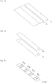
- FIGS. 7A to 7F are schematic views showing the manufacturing step.
- long plate-like members 21 and 22 are formed by cutting a film made of a thermoplastic polyurethane having a rectangular plate shape, as shown in FIG. 7A .
- the two plate-like members 21 and 22 having been overlapped are adhered by adhesion portions at least at two positions which are spaced apart from each other, as shown in FIG. 7C .
- the plate-like members are adhered by adhesion portions 2a to 2h at eight positions.
- the adhesion portions 2a to 2h are thermally deposited, for example, by a welder process.
- a plurality of through holes 4 is formed in the two plate-like members 21 and 22 according to a punching process, as shown in FIG. 7D .
- the through holes 4 are formed while avoiding the adhesion portions 2a to 2h, for keeping the strength of the plate-like members 21 and 22.
- the cushion layer 5 is attached to one plate-like member 21 among the two plate-like members 21 and 22 by a double-stick tape 52, as shown in FIG. 7E .
- the supporting members 3 are respectively inserted between the two plate-like members 21 and 22 between two adjacent adhesion portions, as shown in FIG. 7F .
- the plate-like members 21 and 22 are attached to the inner surface 13a of the tread portion by a double-stick tape 53 so that the space 20 is formed between the outer surface of the plate-like member 21 and the inner surface 13a of the tread portion.
Landscapes
- Engineering & Computer Science (AREA)
- Mechanical Engineering (AREA)
- Tires In General (AREA)
Abstract
Description
- The present invention relates to a pneumatic tire which can reduce a cavity resonance noise by attaching a plate-like member to an inner surface of a tread portion, and a method of manufacturing the pneumatic tire.
- When a vehicle travels on a rough road surface or climbs over a joint of the road surface, a sound called as a road noise may be generated within the vehicle. The road noise is one of the sound with which a tire is involved. In the case that the tire is vibrated by an input caused by irregularity on the road surface, a cavity resonance noise is excited in an internal portion of the tire by the oscillation, and the sound is caused within the vehicle.
-
Patent Document 1 describes a pneumatic tire in which a sound control material made of a sponge material is disposed in a tire inner cavity which is surrounded by a rim and the pneumatic tire, for reducing the road noise. However, there is the possibility that the sponge material mentioned above causes increase in the weight of a whole tire, resulting in a lowered fuel efficiency. Further, there is a problem that a cost increase is caused since a lot of sponge material is required. - Patent Document 2 describes a pneumatic tire in which a partition wall comparting an air chamber in a circumferential direction is provided within the air chamber, which is formed between a tire inner peripheral surface and a rim outer peripheral surface, for the purpose of preventing increase in the road noise while suppressing a great cost increase.
- An equivalent length of an air column within the air chamber becomes short by comparting the air chamber in the circumferential direction by the partition wall, and it is possible to shift a resonant frequency of an air column resonance. As a result, it is possible to prevent the road noise from being increased by the air column resonance.
- Further,
Patent Document 3 describes a pneumatic tire in which an inner wall of the tire is provided with a thin elastic divider plate extending approximately in an axial direction within the tire inner cavity, for the purpose of reducing the load noise which is caused by the cavity resonance noise, while suppressing the increase of the weight. A sound pressure mode is changed in a whole of the tire inner cavity by the provision of the elastic divider plate within the tire inner cavity, and an in-vehicle sound level is reduced. - However, the partition wall and the divider plate oscillate themselves and may increase the road noise caused by the cavity resonance noise by serving a new sound source.
-
- Patent Document 1:
JP-A-2006-306302 - Patent Document 2:
JP-A-7-117404 - Patent Document 3:
JP-A-5-294102 - Accordingly, an object of the present invention is to provide a pneumatic tire which can reduce a cavity resonance noise while suppressing weight increase and cost increase, and a method of manufacturing the pneumatic tire.
- The object can be achieved by the following present invention. That is, the present invention provides a pneumatic tire including two plate-like members which have a plurality of through holes formed therein, and are adhered to each other by adhesion portions at least at two positions spaced apart from each other, and a supporting member which is inserted between the two plate-like members between the adhesion portions being adjacent to each other, wherein a part of an outer surface of one of the two plate-like members is attached to an inner surface of a tread portion so that a space is formed between the outer surface of the one of the two plate-like members that are adhered and the inner surface of the tread portion.
- In the pneumatic tire according to the present invention, two plate-like members having a plurality of through holes formed therein are attached to the inner surface of the tread portion. More specifically, the two plate-like members are adhered to each other by the adhesion portions at least at two positions which are spaced apart from each other, and a part of the outer surface of one of the two plate-like members is attached to the inner surface of the tread portion so that a space is formed between the outer surface of the one of the two plate-like members and the inner surface of the tread portion.
- As a result, a plurality of through holes is formed in the two plate-like members which are in a floating state from the inner surface of the tread portion. In general, when the sound passes through the through hole, there are generated the viscous damping caused by the friction between the air and the inner wall surface of the through hole, and the pressure loss damping caused by the vortex generated by the passing. Therefore, the sound is damped. As a result, the sound within the tire passes through the through hole by attaching the plate-like member having the through holes formed therein to the inner surface of the tread portion, whereby it is possible to damp and reduce the cavity resonance noise.
- Further, since it is not necessary to provide a lot of noise absorbing material and sound control material such as sponge material, it is possible to suppress increase of the weight and increase of the cost. Further, in the present invention, since the supporting member is inserted between the two plate-like members between the adjacent adhesion portions, it is possible to prevent a situation where the plate-like member is crushed against the inner surface of the tread portion due to the centrifugal force in association with the rotation of the tire and, thereby, the through holes are closed. As a result, it is possible to damp and reduce the cavity resonance noise not only at a low speed to a middle speed, but also at a high speed.
- In the pneumatic tire according to the present invention, the adhesion portions at the two positions may be arranged along a tire circumferential direction.
- According to the structure, since the air flow in the tire circumferential direction generated within the tire easily passes through the through holes, it is possible to effectively reduce the cavity resonance noise.
- In the pneumatic tire according to the present invention, the outer surface of the one of the two plate-like members may be attached to the inner surface of the tread portion in a portion which is closer to an outer side than to the adhesion portions at the two positions.
- According to the structure, a space tends to be formed between the plate-like member facing to the inner surface of the tread portion among the two plate-like members and the inner surface of the tread portion, and it is possible to effectively reduce the cavity resonance noise by the through hole.
- In the pneumatic tire according to the present invention, the two plate-like members may be adhered to each other at the adhesion portions at three or more positions which are spaced apart from one another at uniform intervals, and the supporting members may be respectively inserted between the two plate-like members between the adjacent adhesion portions, and the two plate-like members may be attached to the inner surface of the tread portion over its whole periphery.
- According to the structure, since the two plate-like members are attached to the inner surface of the tread portion over a whole periphery, it is possible to effectively reduce the cavity resonance noise by the through hole. Further, it is possible to suppress deterioration of the uniformity and the weight balance by arranging the supporting members at uniform intervals over a whole periphery in the tire circumferential direction.
- Further the present invention provides a method of manufacturing a pneumatic tire, the method including an adhesion step of adhering two plate-like members, which are overlapped, to each other by adhesion portions at least at two positions which are spaced apart from each other, a punching step of forming a plurality of through holes in the two plate-like members, an insertion step of inserting a supporting member between the two plate-like members between the adjacent adhesion portions, and an attachment step of attaching a part of an outer surface of one of the two plate-like members to an inner surface of a tread portion so that a space is formed between the outer surface of the one of the adhered two plate-like members and the inner surface of the tread portion.
- In the pneumatic tire manufactured by the manufacturing method according to the present invention, two plate-like members having a plurality of through holes formed therein are attached to the inner surface of the tread portion. More specifically, the two plate-like members are adhered to each other by the adhesion portions at least two positions which are spaced apart from each other, and a part of the outer surface of one of the two plate-like members is attached to the inner surface of the tread portion so that a space is formed between the outer surface of one of the adhered two plate-like members and the inner surface of the tread portion.
- As a result, a plurality of through holes is formed in the two plate-like members which are in a floating state from the inner surface of the tread portion. In general, when the sound passes through the through hole, there are generated the viscous damping caused by the friction between the air and the inner wall surface of the through hole, and the pressure loss damping caused by the vortex generated by the passing. Therefore, the sound is damped.
- As a result, the sound within the tire passes through the through hole by attaching the plate-like member having the through holes formed therein to the inner surface of the tread portion, whereby it is possible to damp and reduce the cavity resonance noise. Further, since it is not necessary to provide a lot of noise absorbing material and sound control material such as sponge material, it is possible to suppress increase of the weight and increase of the cost.
- Further, in the pneumatic tire manufactured by the manufacturing method according to the present invention, since the supporting member is inserted between the two plate-like members between the adjacent adhesion portions, it is possible to prevent a situation where the plate-like members is crushed against the inner surface of the tread portion due to the centrifugal force in association with the rotation of the tire and, thereby, the through holes are closed. As a result, it is possible to damp and reduce the cavity resonance noise not only at a low speed to a middle speed, but also at a high speed.
- In the method of manufacturing a pneumatic tire according to the present invention, the adhesion step may be carried out before the punching step.
- According to the structure, since the through holes can be formed simultaneously in the two plate-like members which are overlapped, it is possible to easily form a plurality of through holes.
- In the method of manufacturing a pneumatic tire according to the present invention, the two plate-like members may be two long plate-like members which are supplied continuously, the two plate-like members may be adhered to each other by the adhesion portions at three or more positions which are spaced apart from one another in a longitudinal direction, in the adhesion step, the supporting members may be inserted respectively between the two plate-like members between the adhesion portions which are adjacent to each other, in the insertion step, and the adhered two plate-like members may be attached to the inner surface of the tread portion over its whole periphery, in the attachment step.
- According to the structure, since the two plate-like members are attached to the inner surface of the tread portion over a whole periphery, it is possible to effectively reduce the cavity resonance noise by the through hole. Further, it is possible to suppress deterioration of the uniformity and the weight balance by arranging the supporting members at uniform intervals over a whole periphery in the tire circumferential direction.
-
- FIG. 1
- is a perspective view showing an example of a pneumatic tire according to the present invention;
- FIG. 2A
- is a tire meridian cross-sectional view of the pneumatic tire;
- FIG. 2B
- is a cross-sectional view in a tire circumferential direction of the pneumatic tire;
- FIG. 3
- is an enlarged cross-sectional view showing the plate-like member in an enlarged manner;
- FIG. 4
- is a plan view of the plate-like member;
- FIG. 5
- is a cross-sectional view in the tire circumferential direction of a pneumatic tire according to the other embodiment;
- FIG. 6
- is a cross-sectional view in the tire circumferential direction of a pneumatic tire according to the other embodiment;
- FIG. 7A
- is a schematic view showing a method of manufacturing a pneumatic tire;
- FIG. 7B
- is a schematic view showing the method of manufacturing the pneumatic tire;
- FIG. 7C
- is a schematic view showing the method of manufacturing the pneumatic tire;
- FIG. 7D
- is a schematic view showing the method of manufacturing the pneumatic tire;
- FIG. 7E
- is a schematic view showing the method of manufacturing the pneumatic tire;
- FIG. 7F
- is a schematic view showing the method of manufacturing the pneumatic tire; and
- FIG. 8
- is a perspective view of a supporting member according to the other embodiment.
- A description will be given below of embodiments according to the present invention with reference to the accompanying drawings.
-
FIG. 1 is a perspective view showing an example of a pneumatic tire.FIG. 2A is an example of a tire meridian cross-sectional view of the pneumatic tire.FIG. 2B is an example of a cross-sectional view in a tire circumferential direction of the pneumatic tire. Here, reference symbol H denotes a tire cross-sectional height. The tire cross-sectional height H is a height from a nominal rim diameter to a tread surface in a state of being filled with a pneumatic pressure prescribed by JATMA, in a tire meridian cross section. - A
pneumatic tire 1 is provided with a pair ofannular bead portions 11,side wall portions 12 which extend to outer sides in a tire diametrical direction from each of thebead portions 11, and atread portion 13 which is connected to outer ends in the tire diametrical direction of each of theside wall portions 12, as shown inFIGS. 1 and2A . - The
pneumatic tire 1 is provided with two plate-like members inner surface 13a of the tread portion. The two plate-like members inner surface 13a of the tread portion by two mountingportions - The two plate-
like members adhesion portions adhesion portions adhesion portions adhesion portions like members - A
support member 3 is inserted between the two plate-like members adhesion portion 2a and theadhesion portion 2b which are adjacent to each other. The supportingmember 3 according to the present embodiment is formed into a tubular shape which extends along the tire width direction WD. Details of the supportingmember 3 will be described later. - A
space 20 is formed between an outer surface of the plate-like member 21 facing to theinner surface 13a of the tread portion among two adhered plate-like members inner surface 13a of the tread portion. In other words, a part of the outer surface of the plate-like member 21 is in non-contact with theinner surface 13a of the tread portion. - The outer surface of the plate-
like member 21 is fixed to theinner surface 13a of the tread portion by the mountingportions like member 21 positioned in the outer side in the tire diametrical direction of the supportingmember 3 is in contact with theinner surface 13a of the tread portion, however, is not fixed to theinner surface 13a of the tread portion. - The
space 20 is an area which is surrounded by the outer surface of the plate-like member 21 and theinner surface 13a of the tread portion, between the adjacent mountingportions - A plurality of through
holes 4 is formed in the two plate-like members holes 4 are formed in a whole surface of the two plate-like members holes 4 which are in contact with the supportingmember 3, and the throughholes 4 which are formed toward thespace 20 without being in contact with the supportingmember 3. - Here, a description will be given of an effect of damping a cavity resonance noise by the through holes 4. When the sound passes through the through
holes 4, the cavity resonance noise is damped by friction between air serving as a medium and an inner wall surface of the through hole 4 (viscous damping). Further, when the sound passes through the throughhole 4, the cavity resonance noise is damped by pressure loss caused by a vortex which is generated by the passing (pressure loss damping). - As a result, since the sound within the tire passes through the through
holes 4 by attaching the plate-like members holes 4 formed therein to theinner surface 13a of the tread portion, it is possible to damp and reduce the cavity resonance noise. - Further, a particle speed of the air is involved with the viscous damping and the pressure loss damping when the sound passes through the through holes 4. In the case that the through
holes 4 are arranged at the positions having the greater particle speed, the cavity resonance noise can be effectively damped. Further, since the air flow is added to the speed, the throughholes 4 are preferably arranged in the place having the air flow, in the rotating tire. -
FIG. 3 is an enlarged cross-sectional view showing the plate-like members holes 4 formed therein in an enlarged manner (in this case, the supportingmember 3 is not shown). The air flow within the tire is shown by arrows. Within the tire, there exist an air flow Sr in the tire diametrical direction which is generated by deformation of the tire caused by the ground on the road surface, and an air flow Sc in the circumferential direction CD which is generated by restoration of the deformation. - Since the sound generated by the input from the road surface and the air flow Sr in the tire diametrical direction pass through the through
holes 4 by arranging the plate-like members inner surface 13a of the tread portion, it is possible to effectively reduce the cavity resonance noise. - Further, since the sound transmitted in the tire circumferential direction CD and the air flow Sc in the tire circumferential direction CD pass through the through
holes 4 by attaching a part of the outer surface of the plate-like member 21 to theinner surface 13a of the tread portion so that thespace 20 is formed between the outer surface of the plate-like member 21 and theinner surface 13a of the tread portion, it is possible to effectively reduce the cavity resonance noise. - Further, the closer to the
inner surface 13a of the tread portion the air flow is, the faster the air flow is. Considering the fact, in the present invention, the plate-like members holes 4 therein are attached to theinner surface 13a of the tread portion. - The supporting
member 3 is inserted between the two plate-like members like members like members inner surface 13a of the tread portion due to centrifugal force and the throughholes 4 are closed when the tire is rotated at a high speed. As a result, there is a risk that the effect of reducing the cavity resonance noise by the throughholes 4 can not be obtained, or is lowered. - On the contrary, the deformation of the plate-
like members like members - According to the present invention, since the plate-
like members member 3 between the two plate-like members - The supporting
member 3 is preferably formed by a porous material. Accordingly, it is possible to obtain a sound absorbing effect of the supportingmember 3 itself while suppressing the increase of the weight by the supportingmember 3. Here, the porous material is constructed, for example, by a sponge and an unwoven fabric. The porous material is not limited to them, however, a sponge made of a soft polyurethane foam is preferably employed. Further, in the case that the unwoven fabric is employed as the porous material, the supportingmember 3 is formed by rounding or folding the unwoven fabric. - The supporting
member 3 according to the present embodiment is formed into a tubular shape which extends along the tire width direction WD. In the case that the supportingmember 3 is formed into the tubular shape, an air layer is formed in an inner portion. As a result, the effect of absorbing the sound passing through the supportingmember 3 made of the porous material is enhanced. - However, the shape of the supporting
member 3 is not particularly limited as long as the shape is the one which can support the plate-like members member 3 does not necessarily support a whole, in the tire width direction, of the plate-like members like members member 3 may be formed into a shape which extends along the tire width direction WD beyond the width in the tire width direction WD of the plate-like members - Further, a cylindrical shape is particularly preferable for the shape of the supporting
member 3. In the case that the supportingmember 3 is formed into the cylindrical shape, the sound absorbing effect can be achieved in relation to the sound from every angle. However, the cross-sectional shape of the supportingmember 3 may be formed into polygonal shapes such as a triangular shape and a quadrangular shape, in addition to the circular shape. - The supporting
member 3 is preferably sandwiched by the plate-like member 21 and the plate-like member 22. In the case that the supportingmember 3 is formed by the porous material as mentioned above, the supportingmember 3 may be inserted between the two plate-like members adhesion portion 2a and theadhesion portion 2b which are adjacent to each other in a state in which the supportingmember 3 is compressed. - A thickness of each of the plate-
like members like members like members - On the contrary, in the case that the thickness of the plate-
like members inner surface 13a of the tread portion is locally increased its weight by the plate-like members - The maximum height Hp of the plate-
like members inner surface 13a of the tread portion in a tire equator is preferably equal to or more than one tenths of the tire cross-sectional height H (or 10 mm). In the case that the maximum height Hp of the plate-like members like members - On the contrary, the maximum height Hp of the plate-
like members like members like members - A width Wp in the tire width direction of the plate-
like members like members like members like members - Although a length Lp in the tire circumferential direction of the plate-
like members like members -
FIG. 4 is a plan view showing a state in which a part of the plate-like member 22 is expanded into a plane shape. A hole diameter φ of the throughhole 4 is preferably between 0.4 mm and 10 mm, and is more preferably between 1 mm and 5 mm. In the case that the hole diameter φ is smaller than 0.4 mm, the resistance when the sound and the air pass through becomes too large. - As a result, it is hard to produce the through hole as well as the through hole is not effective. On the contrary, in the case that the hole diameter φ is larger than 10 mm, the resistance when the sound and the air pass through becomes too small. As a result, the damping effect becomes small.
- Further, a hole area rate P is preferably between 1 % and 20 %, and more preferably between 1 % and 10 %. In the case that the hole area rate P is smaller than 1 %, the resistance when the sound and the air pass through becomes too large. As a result, the hole is not effective. On the contrary, in the case that the hole area rate P is larger than 20 %, the resistance when the sound and the air pass through becomes too small. As a result, the damping effect becomes small.
- On the assumption that a hole distance between the through
holes 4 is t, the hole area rate P in the case that a plurality of throughholes 4 is arranged in parallel vertically and laterally such as the present embodiment is defined by an formula P = (π x φ2)/(4 x t2). For example, on the assumption that the hole diameter φ is 3 mm and the hole distance t is 10 mm, the hole area rate P is about 7 %. - The hole distance t between the through
holes 4 can be appropriately set by the hole area rate P and the hole diameter φ while using the formula mentioned above, however, the hole distance t is preferably between 1 mm and 30 mm and is more preferably between 5 mm and 15 mm, for example. In the case that the hole distance t is smaller than 1 mm, the number of the holes is necessarily increased. - As a result, the resistance when the sound and the air pass through becomes too small, the damping effect becomes small, and a strength of the plate itself is further reduced. On the contrary, in the case that the hole distance t is larger than 30 mm, the number of the holes is necessarily reduced, and the obtained damping effect becomes small.
- The plate-
like members - The plate-
like member 21 is attached to theinner surface 13a of the tread portion by the mountingportions like member 21 is fixed to theinner surface 13a of the tread portion by an adhesive agent or a double-stick tape. At this time, the plate-like member 21 is preferably fixed to theinner surface 13a of the tread portion via acushion layer 5, as shown inFIG. 5 . Thecushion layer 5 is constructed by a cushion layermain body 51 having a stretching property, and double-stick tapes main body 51. - Accordingly, the cushion layer
main body 51 in thecushion layer 5 is deformed, and can follow the shape of the curved surface of theinner surface 13a of the tread portion and the deformation at the grounding time. As a result, it is possible to stably fix the plate-like member 21 to theinner surface 13a of the tread portion. - The total weight of the plate-
like members like members inner surface 13a of the tread portion, and tends to deteriorate a high-speed uniformity and increase the vibration caused thereby and the ride quality. In the case that thecushion layer 5 described above is provided, a total weight including the plate-like members member 3 and thecushion layer 5 is preferably set to be equal to or less than 20 g, and more preferably set to be equal to or less than 15 g. - In the first embodiment described above, there is shown the example which is provided with two plate-
like members holes 4 formed therein and adhered to each other byadhesion portions member 3 is inserted between the two plate-like members adjacent adhesion portions - However, as shown in
FIG. 6 , the two plate-like members adhesion portions members 3 may be respectively inserted between the two plate-like members adjacent adhesion portions like members inner surface 13a of the tread portion over a whole periphery. - Next, a description will be given of a method of manufacturing the pneumatic tire. The method of manufacturing the pneumatic tire according to the present invention includes an adhesion step of adhering the two plate-like members, which are overlapped, to each other by adhesion portions at least at two positions which are spaced apart from each other, a punching step of forming a plurality of through holes in two plate-like members, an insertion step of inserting a supporting member between the two plate-like members between the adjacent adhesion portions, and an attachment step of attaching a part of an outer surface of one of the two plate-like members to an inner surface of a tread portion so that a space is formed between the outer surface of one of two adhered plate-like members and the inner surface of the tread portion.
-
FIGS. 7A to 7F are schematic views showing the manufacturing step. - First of all, long plate-
like members FIG. 7A . - Next, the two plate-
like members FIG. 7B . - Next, the two plate-
like members FIG. 7C . In the present embodiment, the plate-like members are adhered byadhesion portions 2a to 2h at eight positions. Theadhesion portions 2a to 2h are thermally deposited, for example, by a welder process. - Next, a plurality of through
holes 4 is formed in the two plate-like members FIG. 7D . The throughholes 4 are formed while avoiding theadhesion portions 2a to 2h, for keeping the strength of the plate-like members - Next, the
cushion layer 5 is attached to one plate-like member 21 among the two plate-like members stick tape 52, as shown inFIG. 7E . - Next, the supporting
members 3 are respectively inserted between the two plate-like members FIG. 7F . - Finally, the plate-
like members inner surface 13a of the tread portion by a double-stick tape 53 so that thespace 20 is formed between the outer surface of the plate-like member 21 and theinner surface 13a of the tread portion. -
- (1) In the embodiment described above, the through
holes 4 of the plate-like member 21 and the throughholes 4 of the plate-like member 22 have the same positions by simultaneously forming the throughholes 4 in relation to the two plate-like members holes 4 formed respectively in the two plate-like members - (2) The adjacent adhesion portions for adhering the two plate-
like members - (3) In the example shown in
FIG. 2B , the outer surface of the plate-like member 21 positioned in the outer side in the tire diametrical direction of the supportingmember 3 comes into contact with theinner surface 13a of the tread portion, however, it is preferable that the outer surface of the plate-like member 21 is not in contact with theinner surface 13a of the tread portion (refer toFIG. 5 ). - (4) In the embodiment described above, the adhesion step is carried out before the punching step, however, the punching step may be carried out before the adhesion step.
- (5) In the embodiment described above, the long plate-
like members like members like members members 3 inserted thereinto may be temporarily wound up to the roll, and the long plate-like members inner surface 13a of the tread portion. - (6) The shape of the supporting
member 3 is not limited to the shape mentioned above. For example, the shape may be a solid circular cylinder shape or a solid square post shape. - (7) Further, the supporting
member 3 is not necessarily formed by the porous material. For example, the supportingmember 3 may be formed by the resin frame as shown inFIG. 8 . As the resin, there can be exemplified the general-purpose resins such as PET, PU, TPU, PVC, PC, PE and PEN. The shape of the frame is not limited to the trapezoidal cross section as shown inFIG. 8 , but may be a triangular cross section or a rectangular cross section.
Claims (11)
- A pneumatic tire (1) comprising:- two plate-like members (21, 22) which have a plurality of through holes (4) formed therein, and are adhered to each other by adhesion portions (2a to 2h) at least at two positions spaced apart from each other; and- a supporting member (3) which is inserted between the two plate-like members (21, 22) between the adhesion portions (2a to 2h) being adjacent to each other,- wherein a part of an outer surface of one of the two plate-like members (21, 22) is attached to an inner surface (13a) of a tread portion (13) so that a space (20) is formed between the outer surface of the one of the two plate-like members (21, 22) that are adhered and the inner surface (13a) of the tread portion (13).
- The pneumatic tire (1) according to claim 1,
wherein the adhesion portions (2a to 2h) at the two positions are arranged along a tire circumferential direction. - The pneumatic tire (1) according to claim 1 or 2,
wherein the outer surface of the one of the two plate-like members (21, 22) is attached to the inner surface (13a) of the tread portion (13) in a portion which is closer to an outer side than to the adhesion portions (2a to 2h) at the two positions. - The pneumatic tire (1) according to any one of claims 1 to 3,
wherein the two plate-like members (21, 22) are adhered to each other at the adhesion portions (2a to 2h) at three or more positions which are spaced apart from one another at uniform intervals, and the supporting members (3) are respectively inserted between the two plate-like members (21, 22) between the adjacent adhesion portions (2a to 2h), and
wherein the two plate-like members (21, 22) are attached to the inner surface (13a) of the tread portion (13) over its whole periphery. - The pneumatic tire (1) according to any one of claims 1 to 4,
wherein one of the plate-like members (21, 22) is fixed to the inner surface (13a) of the tread portion (13) by means of a cushion layer (5). - The pneumatic tire (1) according to claim 5,
wherein the cushion layer (5) comprises a cushion layer main body (51) having a stretching property and double-stick tapes (52, 53) on both sides of the cushion layer main body (51). - The pneumatic tire (1) according to any one of claims 1 to 6,
wherein the plate-like members (21, 22) are made of general purpose resins, in particular PET, PU, TPU, PVC, PE and PEN. - The pneumatic tire (1) according to any one of claims 1 to 7,
wherein the supporting member (3) is made from a porous material in particular a sponge and an unwoven fabric. - A method of manufacturing a pneumatic tire,
the method comprising:- an adhesion step of adhering two plate-like members (21, 22), which are overlapped, to each other by adhesion portions (2a to 2h) at least at two positions which are spaced apart from each other;- a punching step of forming a plurality of through holes (4) in the two plate-like members (21, 22);- an insertion step of inserting a supporting member (3) between the two plate-like members (21, 22) between the adjacent adhesion portions (2a to 2h); and- an attachment step of attaching a part of an outer surface of one of the two plate-like members (21, 22) to an inner surface (13a) of a tread portion (13) so that a space (20) is formed between the outer surface of the one of the adhered two plate-like members (21, 22) and the inner surface (13a) of the tread portion (13). - The method of manufacturing the pneumatic tire according to claim 9,
wherein the adhesion step is carried out before the punching step. - The method of manufacturing the pneumatic tire according to claim 9 or 10,
wherein the two plate-like members (21, 22) are two long plate-like members (21, 22) which are supplied continuously,
wherein the two plate-like members (21, 22) are adhered to each other by the adhesion portions (2a to 2h) at three or more positions which are spaced apart from one another in a longitudinal direction, in the adhesion step;
wherein the supporting members (3) are inserted respectively between the two plate-like members (21, 22) between the adhesion portions (2a to 2h) which are adjacent to each other, in the insertion step; and
wherein the adhered two plate-like members (21, 22) are attached to the inner surface (13a) of the tread portion (13) over its whole periphery, in the attachment step.
Applications Claiming Priority (1)
| Application Number | Priority Date | Filing Date | Title |
|---|---|---|---|
| JP2016096903A JP6272944B2 (en) | 2016-05-13 | 2016-05-13 | Pneumatic tire and method for manufacturing pneumatic tire |
Publications (2)
| Publication Number | Publication Date |
|---|---|
| EP3246182A1 true EP3246182A1 (en) | 2017-11-22 |
| EP3246182B1 EP3246182B1 (en) | 2019-09-25 |
Family
ID=58638751
Family Applications (1)
| Application Number | Title | Priority Date | Filing Date |
|---|---|---|---|
| EP17168373.3A Active EP3246182B1 (en) | 2016-05-13 | 2017-04-27 | Pneumatic tire and method of manufacturing pneumatic tire |
Country Status (4)
| Country | Link |
|---|---|
| US (1) | US10556468B2 (en) |
| EP (1) | EP3246182B1 (en) |
| JP (1) | JP6272944B2 (en) |
| CN (1) | CN107444030B (en) |
Cited By (2)
| Publication number | Priority date | Publication date | Assignee | Title |
|---|---|---|---|---|
| IT201900014673A1 (en) * | 2019-08-12 | 2021-02-12 | Bridgestone Europe Nv Sa | TIRE INCLUDING A NOISE REDUCTION STRUCTURE |
| WO2022149114A1 (en) * | 2021-01-11 | 2022-07-14 | 3M Innovative Properties Company | Discrete sound absorbers for tire cavity noise reduction |
Families Citing this family (5)
| Publication number | Priority date | Publication date | Assignee | Title |
|---|---|---|---|---|
| JP6291520B2 (en) * | 2016-05-13 | 2018-03-14 | 東洋ゴム工業株式会社 | Pneumatic tire and method for manufacturing pneumatic tire |
| JP6994373B2 (en) * | 2017-12-08 | 2022-01-14 | Toyo Tire株式会社 | How to make a pneumatic tire |
| JP7238562B2 (en) | 2019-04-11 | 2023-03-14 | 横浜ゴム株式会社 | pneumatic tire |
| KR102044888B1 (en) | 2019-04-12 | 2019-11-14 | 한국타이어앤테크놀로지 주식회사 | Pneumatic tire comprising resonance noise reduction structure |
| KR102351699B1 (en) * | 2020-02-17 | 2022-01-17 | 한국타이어앤테크놀로지 주식회사 | Tires with self generation and sound absorption |
Citations (7)
| Publication number | Priority date | Publication date | Assignee | Title |
|---|---|---|---|---|
| JPH05294102A (en) | 1992-04-17 | 1993-11-09 | Bridgestone Corp | Pneumatic tire |
| JPH07117404A (en) | 1993-10-28 | 1995-05-09 | Mitsubishi Motors Corp | Partition-equipped tire structure |
| US20020033215A1 (en) * | 2000-06-05 | 2002-03-21 | Chieko Aoki | Noise damper for pneumatic tire |
| JP2004082947A (en) * | 2002-08-28 | 2004-03-18 | Tokai Rubber Ind Ltd | Soundproof tire |
| JP2006306302A (en) | 2005-04-28 | 2006-11-09 | Sumitomo Rubber Ind Ltd | Assembly of pneumatic tire and rim |
| US20120325383A1 (en) * | 2011-06-24 | 2012-12-27 | Gm Global Technolofgy Operations Llc | Acoustical core for absorbing noise within a tire interior cavity |
| US20160031269A1 (en) * | 2014-08-01 | 2016-02-04 | Toyo Tire & Rubber Co., Ltd. | Pneumatic tire |
Family Cites Families (8)
| Publication number | Priority date | Publication date | Assignee | Title |
|---|---|---|---|---|
| US4755006A (en) * | 1986-09-25 | 1988-07-05 | Clay Sean S C | Dynamic wheel balancing device |
| JPH031805U (en) * | 1989-05-29 | 1991-01-10 | ||
| JP4415738B2 (en) * | 2004-04-14 | 2010-02-17 | 横浜ゴム株式会社 | Tire wheel assembly and run-flat core |
| JP2008080969A (en) * | 2006-09-27 | 2008-04-10 | Bridgestone Corp | Pneumatic tire and wheel structure |
| FR2908068B1 (en) * | 2006-11-02 | 2009-01-16 | Michelin Soc Tech | METHOD FOR MOLDING A PNEUMATIC HAVING IMPROVED NOISE PERFORMANCE |
| JP6446936B2 (en) * | 2014-09-18 | 2019-01-09 | 横浜ゴム株式会社 | Tire noise reduction device and pneumatic tire |
| JP6277111B2 (en) * | 2014-11-17 | 2018-02-07 | 東洋ゴム工業株式会社 | Pneumatic tire |
| JP6620008B2 (en) * | 2015-12-21 | 2019-12-11 | 株式会社ブリヂストン | Pneumatic tire and tire / rim assembly |
-
2016
- 2016-05-13 JP JP2016096903A patent/JP6272944B2/en active Active
-
2017
- 2017-04-14 CN CN201710244792.0A patent/CN107444030B/en active Active
- 2017-04-27 EP EP17168373.3A patent/EP3246182B1/en active Active
- 2017-04-27 US US15/498,975 patent/US10556468B2/en active Active
Patent Citations (7)
| Publication number | Priority date | Publication date | Assignee | Title |
|---|---|---|---|---|
| JPH05294102A (en) | 1992-04-17 | 1993-11-09 | Bridgestone Corp | Pneumatic tire |
| JPH07117404A (en) | 1993-10-28 | 1995-05-09 | Mitsubishi Motors Corp | Partition-equipped tire structure |
| US20020033215A1 (en) * | 2000-06-05 | 2002-03-21 | Chieko Aoki | Noise damper for pneumatic tire |
| JP2004082947A (en) * | 2002-08-28 | 2004-03-18 | Tokai Rubber Ind Ltd | Soundproof tire |
| JP2006306302A (en) | 2005-04-28 | 2006-11-09 | Sumitomo Rubber Ind Ltd | Assembly of pneumatic tire and rim |
| US20120325383A1 (en) * | 2011-06-24 | 2012-12-27 | Gm Global Technolofgy Operations Llc | Acoustical core for absorbing noise within a tire interior cavity |
| US20160031269A1 (en) * | 2014-08-01 | 2016-02-04 | Toyo Tire & Rubber Co., Ltd. | Pneumatic tire |
Cited By (2)
| Publication number | Priority date | Publication date | Assignee | Title |
|---|---|---|---|---|
| IT201900014673A1 (en) * | 2019-08-12 | 2021-02-12 | Bridgestone Europe Nv Sa | TIRE INCLUDING A NOISE REDUCTION STRUCTURE |
| WO2022149114A1 (en) * | 2021-01-11 | 2022-07-14 | 3M Innovative Properties Company | Discrete sound absorbers for tire cavity noise reduction |
Also Published As
| Publication number | Publication date |
|---|---|
| JP6272944B2 (en) | 2018-01-31 |
| US10556468B2 (en) | 2020-02-11 |
| CN107444030B (en) | 2019-07-09 |
| EP3246182B1 (en) | 2019-09-25 |
| JP2017202788A (en) | 2017-11-16 |
| US20170326923A1 (en) | 2017-11-16 |
| CN107444030A (en) | 2017-12-08 |
Similar Documents
| Publication | Publication Date | Title |
|---|---|---|
| EP3246182B1 (en) | Pneumatic tire and method of manufacturing pneumatic tire | |
| EP3246183B1 (en) | Pneumatic tire and method of manufacturing pneumatic tire | |
| US10000096B2 (en) | Pneumatic tire | |
| US20160031269A1 (en) | Pneumatic tire | |
| US8109361B2 (en) | Solid-borne sound reducing structure | |
| JP4561960B2 (en) | Speaker diaphragm | |
| US20120325383A1 (en) | Acoustical core for absorbing noise within a tire interior cavity | |
| EP2611630B1 (en) | Tyre cavity noise absorber | |
| JP2013536783A5 (en) | ||
| US11541699B2 (en) | Tire noise reduction device and pneumatic tire provided with same | |
| EP3640061B1 (en) | Pneumatic tire | |
| EP3613615A1 (en) | Pneumatic tire | |
| JP4533130B2 (en) | Pneumatic tire and rim assembly | |
| TWI835518B (en) | A type of loudspeaker | |
| US20220176752A1 (en) | Pneumatic tire | |
| JP6994373B2 (en) | How to make a pneumatic tire | |
| CN114193980A (en) | Pneumatic tire and method for manufacturing pneumatic tire | |
| JP2002307905A (en) | Assembly of pneumatic tire and rim | |
| JP2007153274A (en) | Assembly of pneumatic tire and rim | |
| JP7132114B2 (en) | Method for manufacturing pneumatic tire and sound absorbing member | |
| JP6561727B2 (en) | Noise reduction device and pneumatic tire provided with the same | |
| JP2015116865A (en) | Pneumatic tire | |
| JP2020093674A (en) | Automobile pneumatic radial tire | |
| KR102310057B1 (en) | sound absorber for tires | |
| JP2019089410A (en) | tire |
Legal Events
| Date | Code | Title | Description |
|---|---|---|---|
| PUAI | Public reference made under article 153(3) epc to a published international application that has entered the european phase |
Free format text: ORIGINAL CODE: 0009012 |
|
| STAA | Information on the status of an ep patent application or granted ep patent |
Free format text: STATUS: THE APPLICATION HAS BEEN PUBLISHED |
|
| AK | Designated contracting states |
Kind code of ref document: A1 Designated state(s): AL AT BE BG CH CY CZ DE DK EE ES FI FR GB GR HR HU IE IS IT LI LT LU LV MC MK MT NL NO PL PT RO RS SE SI SK SM TR |
|
| AX | Request for extension of the european patent |
Extension state: BA ME |
|
| STAA | Information on the status of an ep patent application or granted ep patent |
Free format text: STATUS: REQUEST FOR EXAMINATION WAS MADE |
|
| 17P | Request for examination filed |
Effective date: 20180522 |
|
| RBV | Designated contracting states (corrected) |
Designated state(s): AL AT BE BG CH CY CZ DE DK EE ES FI FR GB GR HR HU IE IS IT LI LT LU LV MC MK MT NL NO PL PT RO RS SE SI SK SM TR |
|
| RIN1 | Information on inventor provided before grant (corrected) |
Inventor name: SAKAKIBARA, KAZUHIRO |
|
| STAA | Information on the status of an ep patent application or granted ep patent |
Free format text: STATUS: EXAMINATION IS IN PROGRESS |
|
| 17Q | First examination report despatched |
Effective date: 20180824 |
|
| GRAP | Despatch of communication of intention to grant a patent |
Free format text: ORIGINAL CODE: EPIDOSNIGR1 |
|
| STAA | Information on the status of an ep patent application or granted ep patent |
Free format text: STATUS: GRANT OF PATENT IS INTENDED |
|
| RAP1 | Party data changed (applicant data changed or rights of an application transferred) |
Owner name: TOYO TIRE CORPORATION |
|
| INTG | Intention to grant announced |
Effective date: 20190409 |
|
| RIN1 | Information on inventor provided before grant (corrected) |
Inventor name: SAKAKIBARA, KAZUHIRO |
|
| GRAS | Grant fee paid |
Free format text: ORIGINAL CODE: EPIDOSNIGR3 |
|
| GRAA | (expected) grant |
Free format text: ORIGINAL CODE: 0009210 |
|
| STAA | Information on the status of an ep patent application or granted ep patent |
Free format text: STATUS: THE PATENT HAS BEEN GRANTED |
|
| AK | Designated contracting states |
Kind code of ref document: B1 Designated state(s): AL AT BE BG CH CY CZ DE DK EE ES FI FR GB GR HR HU IE IS IT LI LT LU LV MC MK MT NL NO PL PT RO RS SE SI SK SM TR |
|
| REG | Reference to a national code |
Ref country code: GB Ref legal event code: FG4D |
|
| RIN1 | Information on inventor provided before grant (corrected) |
Inventor name: SAKAKIBARA, KAZUHIRO |
|
| REG | Reference to a national code |
Ref country code: CH Ref legal event code: EP |
|
| REG | Reference to a national code |
Ref country code: AT Ref legal event code: REF Ref document number: 1183454 Country of ref document: AT Kind code of ref document: T Effective date: 20191015 |
|
| REG | Reference to a national code |
Ref country code: IE Ref legal event code: FG4D |
|
| REG | Reference to a national code |
Ref country code: DE Ref legal event code: R096 Ref document number: 602017007240 Country of ref document: DE |
|
| REG | Reference to a national code |
Ref country code: NL Ref legal event code: MP Effective date: 20190925 |
|
| PG25 | Lapsed in a contracting state [announced via postgrant information from national office to epo] |
Ref country code: HR Free format text: LAPSE BECAUSE OF FAILURE TO SUBMIT A TRANSLATION OF THE DESCRIPTION OR TO PAY THE FEE WITHIN THE PRESCRIBED TIME-LIMIT Effective date: 20190925 Ref country code: SE Free format text: LAPSE BECAUSE OF FAILURE TO SUBMIT A TRANSLATION OF THE DESCRIPTION OR TO PAY THE FEE WITHIN THE PRESCRIBED TIME-LIMIT Effective date: 20190925 Ref country code: BG Free format text: LAPSE BECAUSE OF FAILURE TO SUBMIT A TRANSLATION OF THE DESCRIPTION OR TO PAY THE FEE WITHIN THE PRESCRIBED TIME-LIMIT Effective date: 20191225 Ref country code: FI Free format text: LAPSE BECAUSE OF FAILURE TO SUBMIT A TRANSLATION OF THE DESCRIPTION OR TO PAY THE FEE WITHIN THE PRESCRIBED TIME-LIMIT Effective date: 20190925 Ref country code: NO Free format text: LAPSE BECAUSE OF FAILURE TO SUBMIT A TRANSLATION OF THE DESCRIPTION OR TO PAY THE FEE WITHIN THE PRESCRIBED TIME-LIMIT Effective date: 20191225 Ref country code: LT Free format text: LAPSE BECAUSE OF FAILURE TO SUBMIT A TRANSLATION OF THE DESCRIPTION OR TO PAY THE FEE WITHIN THE PRESCRIBED TIME-LIMIT Effective date: 20190925 |
|
| REG | Reference to a national code |
Ref country code: LT Ref legal event code: MG4D |
|
| PG25 | Lapsed in a contracting state [announced via postgrant information from national office to epo] |
Ref country code: LV Free format text: LAPSE BECAUSE OF FAILURE TO SUBMIT A TRANSLATION OF THE DESCRIPTION OR TO PAY THE FEE WITHIN THE PRESCRIBED TIME-LIMIT Effective date: 20190925 Ref country code: GR Free format text: LAPSE BECAUSE OF FAILURE TO SUBMIT A TRANSLATION OF THE DESCRIPTION OR TO PAY THE FEE WITHIN THE PRESCRIBED TIME-LIMIT Effective date: 20191226 Ref country code: RS Free format text: LAPSE BECAUSE OF FAILURE TO SUBMIT A TRANSLATION OF THE DESCRIPTION OR TO PAY THE FEE WITHIN THE PRESCRIBED TIME-LIMIT Effective date: 20190925 |
|
| REG | Reference to a national code |
Ref country code: AT Ref legal event code: MK05 Ref document number: 1183454 Country of ref document: AT Kind code of ref document: T Effective date: 20190925 |
|
| PG25 | Lapsed in a contracting state [announced via postgrant information from national office to epo] |
Ref country code: ES Free format text: LAPSE BECAUSE OF FAILURE TO SUBMIT A TRANSLATION OF THE DESCRIPTION OR TO PAY THE FEE WITHIN THE PRESCRIBED TIME-LIMIT Effective date: 20190925 Ref country code: PT Free format text: LAPSE BECAUSE OF FAILURE TO SUBMIT A TRANSLATION OF THE DESCRIPTION OR TO PAY THE FEE WITHIN THE PRESCRIBED TIME-LIMIT Effective date: 20200127 Ref country code: PL Free format text: LAPSE BECAUSE OF FAILURE TO SUBMIT A TRANSLATION OF THE DESCRIPTION OR TO PAY THE FEE WITHIN THE PRESCRIBED TIME-LIMIT Effective date: 20190925 Ref country code: AL Free format text: LAPSE BECAUSE OF FAILURE TO SUBMIT A TRANSLATION OF THE DESCRIPTION OR TO PAY THE FEE WITHIN THE PRESCRIBED TIME-LIMIT Effective date: 20190925 Ref country code: RO Free format text: LAPSE BECAUSE OF FAILURE TO SUBMIT A TRANSLATION OF THE DESCRIPTION OR TO PAY THE FEE WITHIN THE PRESCRIBED TIME-LIMIT Effective date: 20190925 Ref country code: IT Free format text: LAPSE BECAUSE OF FAILURE TO SUBMIT A TRANSLATION OF THE DESCRIPTION OR TO PAY THE FEE WITHIN THE PRESCRIBED TIME-LIMIT Effective date: 20190925 Ref country code: EE Free format text: LAPSE BECAUSE OF FAILURE TO SUBMIT A TRANSLATION OF THE DESCRIPTION OR TO PAY THE FEE WITHIN THE PRESCRIBED TIME-LIMIT Effective date: 20190925 Ref country code: NL Free format text: LAPSE BECAUSE OF FAILURE TO SUBMIT A TRANSLATION OF THE DESCRIPTION OR TO PAY THE FEE WITHIN THE PRESCRIBED TIME-LIMIT Effective date: 20190925 Ref country code: AT Free format text: LAPSE BECAUSE OF FAILURE TO SUBMIT A TRANSLATION OF THE DESCRIPTION OR TO PAY THE FEE WITHIN THE PRESCRIBED TIME-LIMIT Effective date: 20190925 |
|
| PG25 | Lapsed in a contracting state [announced via postgrant information from national office to epo] |
Ref country code: SM Free format text: LAPSE BECAUSE OF FAILURE TO SUBMIT A TRANSLATION OF THE DESCRIPTION OR TO PAY THE FEE WITHIN THE PRESCRIBED TIME-LIMIT Effective date: 20190925 Ref country code: CZ Free format text: LAPSE BECAUSE OF FAILURE TO SUBMIT A TRANSLATION OF THE DESCRIPTION OR TO PAY THE FEE WITHIN THE PRESCRIBED TIME-LIMIT Effective date: 20190925 Ref country code: IS Free format text: LAPSE BECAUSE OF FAILURE TO SUBMIT A TRANSLATION OF THE DESCRIPTION OR TO PAY THE FEE WITHIN THE PRESCRIBED TIME-LIMIT Effective date: 20200224 Ref country code: SK Free format text: LAPSE BECAUSE OF FAILURE TO SUBMIT A TRANSLATION OF THE DESCRIPTION OR TO PAY THE FEE WITHIN THE PRESCRIBED TIME-LIMIT Effective date: 20190925 |
|
| REG | Reference to a national code |
Ref country code: DE Ref legal event code: R097 Ref document number: 602017007240 Country of ref document: DE |
|
| PG2D | Information on lapse in contracting state deleted |
Ref country code: IS |
|
| PG25 | Lapsed in a contracting state [announced via postgrant information from national office to epo] |
Ref country code: DK Free format text: LAPSE BECAUSE OF FAILURE TO SUBMIT A TRANSLATION OF THE DESCRIPTION OR TO PAY THE FEE WITHIN THE PRESCRIBED TIME-LIMIT Effective date: 20190925 Ref country code: IS Free format text: LAPSE BECAUSE OF FAILURE TO SUBMIT A TRANSLATION OF THE DESCRIPTION OR TO PAY THE FEE WITHIN THE PRESCRIBED TIME-LIMIT Effective date: 20200126 |
|
| PLBE | No opposition filed within time limit |
Free format text: ORIGINAL CODE: 0009261 |
|
| STAA | Information on the status of an ep patent application or granted ep patent |
Free format text: STATUS: NO OPPOSITION FILED WITHIN TIME LIMIT |
|
| 26N | No opposition filed |
Effective date: 20200626 |
|
| PG25 | Lapsed in a contracting state [announced via postgrant information from national office to epo] |
Ref country code: MC Free format text: LAPSE BECAUSE OF FAILURE TO SUBMIT A TRANSLATION OF THE DESCRIPTION OR TO PAY THE FEE WITHIN THE PRESCRIBED TIME-LIMIT Effective date: 20190925 Ref country code: SI Free format text: LAPSE BECAUSE OF FAILURE TO SUBMIT A TRANSLATION OF THE DESCRIPTION OR TO PAY THE FEE WITHIN THE PRESCRIBED TIME-LIMIT Effective date: 20190925 |
|
| REG | Reference to a national code |
Ref country code: CH Ref legal event code: PL |
|
| PG25 | Lapsed in a contracting state [announced via postgrant information from national office to epo] |
Ref country code: CH Free format text: LAPSE BECAUSE OF NON-PAYMENT OF DUE FEES Effective date: 20200430 Ref country code: LU Free format text: LAPSE BECAUSE OF NON-PAYMENT OF DUE FEES Effective date: 20200427 Ref country code: LI Free format text: LAPSE BECAUSE OF NON-PAYMENT OF DUE FEES Effective date: 20200430 |
|
| REG | Reference to a national code |
Ref country code: BE Ref legal event code: MM Effective date: 20200430 |
|
| PG25 | Lapsed in a contracting state [announced via postgrant information from national office to epo] |
Ref country code: BE Free format text: LAPSE BECAUSE OF NON-PAYMENT OF DUE FEES Effective date: 20200430 |
|
| PG25 | Lapsed in a contracting state [announced via postgrant information from national office to epo] |
Ref country code: IE Free format text: LAPSE BECAUSE OF NON-PAYMENT OF DUE FEES Effective date: 20200427 |
|
| GBPC | Gb: european patent ceased through non-payment of renewal fee |
Effective date: 20210427 |
|
| PG25 | Lapsed in a contracting state [announced via postgrant information from national office to epo] |
Ref country code: GB Free format text: LAPSE BECAUSE OF NON-PAYMENT OF DUE FEES Effective date: 20210427 |
|
| PG25 | Lapsed in a contracting state [announced via postgrant information from national office to epo] |
Ref country code: TR Free format text: LAPSE BECAUSE OF FAILURE TO SUBMIT A TRANSLATION OF THE DESCRIPTION OR TO PAY THE FEE WITHIN THE PRESCRIBED TIME-LIMIT Effective date: 20190925 Ref country code: MT Free format text: LAPSE BECAUSE OF FAILURE TO SUBMIT A TRANSLATION OF THE DESCRIPTION OR TO PAY THE FEE WITHIN THE PRESCRIBED TIME-LIMIT Effective date: 20190925 Ref country code: CY Free format text: LAPSE BECAUSE OF FAILURE TO SUBMIT A TRANSLATION OF THE DESCRIPTION OR TO PAY THE FEE WITHIN THE PRESCRIBED TIME-LIMIT Effective date: 20190925 |
|
| PG25 | Lapsed in a contracting state [announced via postgrant information from national office to epo] |
Ref country code: MK Free format text: LAPSE BECAUSE OF FAILURE TO SUBMIT A TRANSLATION OF THE DESCRIPTION OR TO PAY THE FEE WITHIN THE PRESCRIBED TIME-LIMIT Effective date: 20190925 |
|
| PGFP | Annual fee paid to national office [announced via postgrant information from national office to epo] |
Ref country code: FR Payment date: 20240308 Year of fee payment: 8 |
|
| PGFP | Annual fee paid to national office [announced via postgrant information from national office to epo] |
Ref country code: DE Payment date: 20240306 Year of fee payment: 8 |