EP3246159A1 - Manufacturing procedure for ceiling trims for vehicles - Google Patents
Manufacturing procedure for ceiling trims for vehicles Download PDFInfo
- Publication number
- EP3246159A1 EP3246159A1 EP16382215.8A EP16382215A EP3246159A1 EP 3246159 A1 EP3246159 A1 EP 3246159A1 EP 16382215 A EP16382215 A EP 16382215A EP 3246159 A1 EP3246159 A1 EP 3246159A1
- Authority
- EP
- European Patent Office
- Prior art keywords
- mould
- sheet
- gas
- phase catalyst
- sandwich
- Prior art date
- Legal status (The legal status is an assumption and is not a legal conclusion. Google has not performed a legal analysis and makes no representation as to the accuracy of the status listed.)
- Granted
Links
Images


Classifications
-
- B—PERFORMING OPERATIONS; TRANSPORTING
- B29—WORKING OF PLASTICS; WORKING OF SUBSTANCES IN A PLASTIC STATE IN GENERAL
- B29C—SHAPING OR JOINING OF PLASTICS; SHAPING OF MATERIAL IN A PLASTIC STATE, NOT OTHERWISE PROVIDED FOR; AFTER-TREATMENT OF THE SHAPED PRODUCTS, e.g. REPAIRING
- B29C51/00—Shaping by thermoforming, i.e. shaping sheets or sheet like preforms after heating, e.g. shaping sheets in matched moulds or by deep-drawing; Apparatus therefor
- B29C51/14—Shaping by thermoforming, i.e. shaping sheets or sheet like preforms after heating, e.g. shaping sheets in matched moulds or by deep-drawing; Apparatus therefor using multilayered preforms or sheets
-
- B—PERFORMING OPERATIONS; TRANSPORTING
- B29—WORKING OF PLASTICS; WORKING OF SUBSTANCES IN A PLASTIC STATE IN GENERAL
- B29C—SHAPING OR JOINING OF PLASTICS; SHAPING OF MATERIAL IN A PLASTIC STATE, NOT OTHERWISE PROVIDED FOR; AFTER-TREATMENT OF THE SHAPED PRODUCTS, e.g. REPAIRING
- B29C39/00—Shaping by casting, i.e. introducing the moulding material into a mould or between confining surfaces without significant moulding pressure; Apparatus therefor
- B29C39/02—Shaping by casting, i.e. introducing the moulding material into a mould or between confining surfaces without significant moulding pressure; Apparatus therefor for making articles of definite length, i.e. discrete articles
- B29C39/12—Making multilayered or multicoloured articles
- B29C39/123—Making multilayered articles
-
- B—PERFORMING OPERATIONS; TRANSPORTING
- B29—WORKING OF PLASTICS; WORKING OF SUBSTANCES IN A PLASTIC STATE IN GENERAL
- B29C—SHAPING OR JOINING OF PLASTICS; SHAPING OF MATERIAL IN A PLASTIC STATE, NOT OTHERWISE PROVIDED FOR; AFTER-TREATMENT OF THE SHAPED PRODUCTS, e.g. REPAIRING
- B29C39/00—Shaping by casting, i.e. introducing the moulding material into a mould or between confining surfaces without significant moulding pressure; Apparatus therefor
- B29C39/22—Component parts, details or accessories; Auxiliary operations
- B29C39/26—Moulds or cores
-
- B—PERFORMING OPERATIONS; TRANSPORTING
- B29—WORKING OF PLASTICS; WORKING OF SUBSTANCES IN A PLASTIC STATE IN GENERAL
- B29C—SHAPING OR JOINING OF PLASTICS; SHAPING OF MATERIAL IN A PLASTIC STATE, NOT OTHERWISE PROVIDED FOR; AFTER-TREATMENT OF THE SHAPED PRODUCTS, e.g. REPAIRING
- B29C39/00—Shaping by casting, i.e. introducing the moulding material into a mould or between confining surfaces without significant moulding pressure; Apparatus therefor
- B29C39/22—Component parts, details or accessories; Auxiliary operations
- B29C39/38—Heating or cooling
-
- B—PERFORMING OPERATIONS; TRANSPORTING
- B29—WORKING OF PLASTICS; WORKING OF SUBSTANCES IN A PLASTIC STATE IN GENERAL
- B29C—SHAPING OR JOINING OF PLASTICS; SHAPING OF MATERIAL IN A PLASTIC STATE, NOT OTHERWISE PROVIDED FOR; AFTER-TREATMENT OF THE SHAPED PRODUCTS, e.g. REPAIRING
- B29C51/00—Shaping by thermoforming, i.e. shaping sheets or sheet like preforms after heating, e.g. shaping sheets in matched moulds or by deep-drawing; Apparatus therefor
- B29C51/26—Component parts, details or accessories; Auxiliary operations
- B29C51/42—Heating or cooling
- B29C51/421—Heating or cooling of preforms, specially adapted for thermoforming
- B29C51/424—Heating or cooling of preforms, specially adapted for thermoforming using a heated fluid
-
- B—PERFORMING OPERATIONS; TRANSPORTING
- B32—LAYERED PRODUCTS
- B32B—LAYERED PRODUCTS, i.e. PRODUCTS BUILT-UP OF STRATA OF FLAT OR NON-FLAT, e.g. CELLULAR OR HONEYCOMB, FORM
- B32B37/00—Methods or apparatus for laminating, e.g. by curing or by ultrasonic bonding
- B32B37/12—Methods or apparatus for laminating, e.g. by curing or by ultrasonic bonding characterised by using adhesives
- B32B37/1207—Heat-activated adhesive
-
- B—PERFORMING OPERATIONS; TRANSPORTING
- B32—LAYERED PRODUCTS
- B32B—LAYERED PRODUCTS, i.e. PRODUCTS BUILT-UP OF STRATA OF FLAT OR NON-FLAT, e.g. CELLULAR OR HONEYCOMB, FORM
- B32B38/00—Ancillary operations in connection with laminating processes
- B32B38/18—Handling of layers or the laminate
- B32B38/1866—Handling of layers or the laminate conforming the layers or laminate to a convex or concave profile
-
- B—PERFORMING OPERATIONS; TRANSPORTING
- B60—VEHICLES IN GENERAL
- B60R—VEHICLES, VEHICLE FITTINGS, OR VEHICLE PARTS, NOT OTHERWISE PROVIDED FOR
- B60R13/00—Elements for body-finishing, identifying, or decorating; Arrangements or adaptations for advertising purposes
- B60R13/02—Internal Trim mouldings ; Internal Ledges; Wall liners for passenger compartments; Roof liners
- B60R13/0212—Roof or head liners
-
- B—PERFORMING OPERATIONS; TRANSPORTING
- B29—WORKING OF PLASTICS; WORKING OF SUBSTANCES IN A PLASTIC STATE IN GENERAL
- B29C—SHAPING OR JOINING OF PLASTICS; SHAPING OF MATERIAL IN A PLASTIC STATE, NOT OTHERWISE PROVIDED FOR; AFTER-TREATMENT OF THE SHAPED PRODUCTS, e.g. REPAIRING
- B29C51/00—Shaping by thermoforming, i.e. shaping sheets or sheet like preforms after heating, e.g. shaping sheets in matched moulds or by deep-drawing; Apparatus therefor
- B29C51/08—Deep drawing or matched-mould forming, i.e. using mechanical means only
- B29C51/082—Deep drawing or matched-mould forming, i.e. using mechanical means only by shaping between complementary mould parts
-
- B—PERFORMING OPERATIONS; TRANSPORTING
- B29—WORKING OF PLASTICS; WORKING OF SUBSTANCES IN A PLASTIC STATE IN GENERAL
- B29K—INDEXING SCHEME ASSOCIATED WITH SUBCLASSES B29B, B29C OR B29D, RELATING TO MOULDING MATERIALS OR TO MATERIALS FOR MOULDS, REINFORCEMENTS, FILLERS OR PREFORMED PARTS, e.g. INSERTS
- B29K2101/00—Use of unspecified macromolecular compounds as moulding material
- B29K2101/10—Thermosetting resins
-
- B—PERFORMING OPERATIONS; TRANSPORTING
- B29—WORKING OF PLASTICS; WORKING OF SUBSTANCES IN A PLASTIC STATE IN GENERAL
- B29K—INDEXING SCHEME ASSOCIATED WITH SUBCLASSES B29B, B29C OR B29D, RELATING TO MOULDING MATERIALS OR TO MATERIALS FOR MOULDS, REINFORCEMENTS, FILLERS OR PREFORMED PARTS, e.g. INSERTS
- B29K2105/00—Condition, form or state of moulded material or of the material to be shaped
- B29K2105/0005—Condition, form or state of moulded material or of the material to be shaped containing compounding ingredients
- B29K2105/0014—Catalysts
-
- B—PERFORMING OPERATIONS; TRANSPORTING
- B29—WORKING OF PLASTICS; WORKING OF SUBSTANCES IN A PLASTIC STATE IN GENERAL
- B29K—INDEXING SCHEME ASSOCIATED WITH SUBCLASSES B29B, B29C OR B29D, RELATING TO MOULDING MATERIALS OR TO MATERIALS FOR MOULDS, REINFORCEMENTS, FILLERS OR PREFORMED PARTS, e.g. INSERTS
- B29K2105/00—Condition, form or state of moulded material or of the material to be shaped
- B29K2105/0097—Glues or adhesives, e.g. hot melts or thermofusible adhesives
-
- B—PERFORMING OPERATIONS; TRANSPORTING
- B29—WORKING OF PLASTICS; WORKING OF SUBSTANCES IN A PLASTIC STATE IN GENERAL
- B29K—INDEXING SCHEME ASSOCIATED WITH SUBCLASSES B29B, B29C OR B29D, RELATING TO MOULDING MATERIALS OR TO MATERIALS FOR MOULDS, REINFORCEMENTS, FILLERS OR PREFORMED PARTS, e.g. INSERTS
- B29K2475/00—Use of PU, i.e. polyureas or polyurethanes or derivatives thereof, as filler
-
- B—PERFORMING OPERATIONS; TRANSPORTING
- B29—WORKING OF PLASTICS; WORKING OF SUBSTANCES IN A PLASTIC STATE IN GENERAL
- B29L—INDEXING SCHEME ASSOCIATED WITH SUBCLASS B29C, RELATING TO PARTICULAR ARTICLES
- B29L2009/00—Layered products
- B29L2009/001—Layered products the layers being loose
-
- B—PERFORMING OPERATIONS; TRANSPORTING
- B29—WORKING OF PLASTICS; WORKING OF SUBSTANCES IN A PLASTIC STATE IN GENERAL
- B29L—INDEXING SCHEME ASSOCIATED WITH SUBCLASS B29C, RELATING TO PARTICULAR ARTICLES
- B29L2031/00—Other particular articles
- B29L2031/30—Vehicles, e.g. ships or aircraft, or body parts thereof
- B29L2031/3005—Body finishings
- B29L2031/3041—Trim panels
-
- B—PERFORMING OPERATIONS; TRANSPORTING
- B32—LAYERED PRODUCTS
- B32B—LAYERED PRODUCTS, i.e. PRODUCTS BUILT-UP OF STRATA OF FLAT OR NON-FLAT, e.g. CELLULAR OR HONEYCOMB, FORM
- B32B37/00—Methods or apparatus for laminating, e.g. by curing or by ultrasonic bonding
- B32B37/12—Methods or apparatus for laminating, e.g. by curing or by ultrasonic bonding characterised by using adhesives
- B32B2037/1253—Methods or apparatus for laminating, e.g. by curing or by ultrasonic bonding characterised by using adhesives curable adhesive
-
- B—PERFORMING OPERATIONS; TRANSPORTING
- B32—LAYERED PRODUCTS
- B32B—LAYERED PRODUCTS, i.e. PRODUCTS BUILT-UP OF STRATA OF FLAT OR NON-FLAT, e.g. CELLULAR OR HONEYCOMB, FORM
- B32B38/00—Ancillary operations in connection with laminating processes
- B32B38/16—Drying; Softening; Cleaning
- B32B38/164—Drying
- B32B2038/166—Removing moisture
-
- B—PERFORMING OPERATIONS; TRANSPORTING
- B32—LAYERED PRODUCTS
- B32B—LAYERED PRODUCTS, i.e. PRODUCTS BUILT-UP OF STRATA OF FLAT OR NON-FLAT, e.g. CELLULAR OR HONEYCOMB, FORM
- B32B2309/00—Parameters for the laminating or treatment process; Apparatus details
- B32B2309/02—Temperature
-
- B—PERFORMING OPERATIONS; TRANSPORTING
- B32—LAYERED PRODUCTS
- B32B—LAYERED PRODUCTS, i.e. PRODUCTS BUILT-UP OF STRATA OF FLAT OR NON-FLAT, e.g. CELLULAR OR HONEYCOMB, FORM
- B32B2605/00—Vehicles
- B32B2605/003—Interior finishings
Definitions
- This invention relates to a manufacturing procedure for ceiling trims for vehicles, which structure comprises at least one first sheet and at least one second sheet of coating that extends along the length of one of the sides that form the first sheet, joined via a layer of heat-stable polyurethane adhesive, which does not use demoulding elements in order to facilitate the extraction of the ceiling trim formed from inside of the mould.
- Said curing consists in an irreversible chemical reaction by which the adhesive hardens, producing a structure of polymer chains that cross link to form a three dimensional network.
- water is usually used as an activating element, and it is normally applied on the adhesive before introducing the different layers that will form the ceiling trim inside the hot thermoforming mould.
- the combined application of pressure and temperature provided by the mould result in the curing of the heat-stable polyurethane adhesive by contact with the layers that form the ceiling trim with the surfaces of the hot mould.
- the adhesive tends to move towards the surfaces of the hot mould until it reaches them, crossing through the layers that are contiguous to the surfaces of said mould due to the effect of the pressure exerted by the mould, which results in its adhesion to them once the adhesive has cured due to the heat provided through the surfaces of the hot mould.
- demoulding agents which act as a barrier between the adhesive that forms part of the layers of the trim and the surfaces of the mould.
- demoulding agents may consist, for example, in liquids demoulding agents that are applied by spraying over the mould surface, or they may be demoulding agents in the form of sheets that are sandwiched between the layers that will make up the trim and the surface of the mould, and which are removed once the trim has been thermoformed and can be reused for a new cycle.
- Patent WO2012031190 shows an example that describes a manufacturing procedure for a ceiling trim that uses a demoulding sheet that prevents the adhesive from sticking to the mould surfaces.
- demoulding sheets mandates the addition of an extra component, which is especially expensive in fast manufacturing processes.
- both the liquid demoulding agents applied on the mould surfaces and the reusable demoulding sheets produce stains on the decorative coating that makes up the visible side of the ceiling trim as a result of the degradation of said demoulding agents over time.
- the object of the invention consists in a manufacturing procedure for ceiling trims for vehicles comprising at least a first coating sheet and at least a second coating sheet that extend along one of the sides forming the first sheet, joined via a heat-stable polyurethane adhesive layer wherein no additional demoulding agents are used to facilitate extraction of the ceiling trim formed within the mould, while at the same time maintaining a good appearance of the ceiling trim obtained.
- thermoforming mould uses a gas-phase catalyst inside the mould and particularly the beginning of its application before the thermoforming mould is completely closed, allows establishing a barrier between the adhesive and the mould surfaces due to the pressure exerted by said gas-phase catalyst on the layers that make up the trim, preventing said adhesive from penetrating the coating layer and reaching the thermoforming mould surfaces once such mould is completely closed.
- another effect of applying the gas-phase catalyst is the curing of at least one part of the adhesive forming the first heat-stable polyurethane adhesive layer, which is closest to the surface of the mould through which the gas-phase catalyst is applied.
- Said part of the already cured heat-stable adhesive layer acts as a barrier, stopping the remaining adhesive forming said layer, such that once the thermoforming mould has been completely closed there is no passage of adhesive through the second coating layer, and therefore there is no contact between the adhesive and the surface of the mould.
- the extraction of the piece once the manufacturing procedure is completed is performed without difficulty and without the risk of marks caused by penetration of the adhesive to the mould or deformations resulting from adhesion of the piece to the surface of the mould.
- the previous step of opening the mould before the adhesive is cured allows evacuating the excess of gas-phase catalyst present inside the mould, thus preventing the presence of moisture in the ceiling trim.
- the first step, step a) comprises arranging a layer "sandwich" (1) formed by at least one first sheet (1.1) a second coating sheet (1.2) that covers one of the sides of the first sheet (1.1) and a first layer of unactivated heat-stable polyurethane adhesive (1.3) between said at least first sheet (1.1) and said second coating sheet (1.2) in order to join them.
- unactivated relates to a state of the heat-stable polyurethane adhesive in which the chemical reaction, which results in its curing in a reasonable time corresponding to the usual time cycles in a ceiling trim manufacturing procedure, cannot occur.
- heat-stable polyurethane adhesives refers to an adhesive to which the corresponding catalyst has not been added, which is a necessary component in order to produce its activation, in a previous step to step b) of introducing the layered sandwich (1) inside the mould (2).
- step b) comprises introducing the sandwich (1) inside a hot thermoforming mould (2) comprising a first half of the mould (2.1) and a second half of the mould (2.2), the temperature of which lies in the range between 100 and 150°C.
- At least one of the halves of the mould (2.1, 2.2) can move between a first position in which the halves (2.1, 2.2) of the mould (2) are at a maximum separation, the mould (2) thus being completely open, and a second position in which the mould (2) is completely closed.
- step c) of the procedure is carried out, which comprises the application of a gas-phase catalyst (3.3).
- Said gas-phase catalyst (3.3) may be for example, steam, DABCO® (trademark of Air Products & Chemicals), diluted in water as a gas phase, an organometallic compound such as DBTL (dibutyl tin dilaurate) diluted in water as a gas phase or a diluted in water as a gas phase.
- DABCO® trademark of Air Products & Chemicals
- DBTL dibutyl tin dilaurate
- step c) is performed before the completion of step d), which comprises the closing of the mould (2), and the end of step c) is performed before the completion of step e), comprising the opening of the mould (2) to evacuate any excess moisture.
- step d) of closing the mould (2) starts with the beginning of the movement of bringing the two halves (2.1, 2.2) of the mould (2) together and ends when said movement stops, resulting in the closing of the mould (2); and step e) of opening the mould (2) starts when the movement of separating the two halves (2.1, 2.2) of the mould (2) starts and ends when said movement stops, resulting in a completely open mould (2).
- the mould (2) comprises means (3) for applying the gas-phase catalyst that in turn comprise means (3.1) for generating the gas-phase catalyst (3.3), and conducts (3.2) provided therein that allow transporting the gas-phase catalyst (3.3) from the means (3.1) for generating the gas-phase catalyst to the interior of the mould (2).
- the application of the gas-phase catalyst (3.3) is performed through the first half of the mould (2.1) that is in contact with the second coating sheet (1.2).
- the application of the gas-phase catalyst (3.3) may also be performed through the second half of the mould (2.2) on a third coating sheet (1.4) that can form part of the sandwich structure (1).
- the application of the gas-phase catalyst (3.3) on the sandwich (1) results in the activation of the adhesive forming part of the first heat-stable polyurethane adhesive layer (1.3) as a result of the effect of the gas-phase catalyst (3.3).
- said application of the gas-phase catalyst (3.3) is performed with sufficient pressure to allow said gas-phase catalyst (3.3) to access the entire heat-stable polyurethane adhesive and thus allow its activation.
- Said pressure is greater than the atmospheric pressure and particularly 2 bars, and in a specific case it is in a range between 2 and 15 bar.
- the application of the gas-phase catalyst (3.3) results in the creation of a barrier between the first heat-stable polyurethane adhesive layer (1.3) and the surface (2.1.1) forming the first half of the mould (2) as a result of the pressure exerted by the gas-phase catalyst (3.3) on the first layer of heat-stable polyurethane adhesive (1.3).
- part (1.3.1) of the first layer of heat-stable polyurethane adhesive (1.3) that is in contact with the second coating sheet (1.2) is cured, preventing the adhesive forming said layer (1.3) from passing through to the second coating sheet (1.2), and therefore preventing contact of said adhesive with the surface (2.1.1) of the first half of the mould (2.1).
- This variant therefore contemplates a sandwich the structure of which also consists of a third coating sheet (1.4) joined to the other side of the first sheet (1.1) via a second heat-stable polyurethane adhesive layer (1.5), as shown in the examples represented in Figures 5B and 5C and described in detail below.
- Step d) is then performed, comprising the closing of the thermoforming mould (2) and thus the application of pressure on the sandwich (1).
- This step d), once step c) is started, is performed by maintaining the introduction of the gas-phase catalyst (3.3) at a pressure of more than 2 bar through the first half of the mould (2.1) and maintaining the circulation of the gas-phase catalyst (3.3) through the sandwich (1).
- Said pressure of the gas-phase catalyst (3.3) results in the discharge thereof from inside the mould (2) as shown in Figure 1A .
- step e) comprising the opening of the mould (2) to evacuate any excess moisture from the sandwich (1) as excess gas in order to prevent the occurrence of moisture in the sandwich (1) as a result of the excess of gas-phase catalyst (3.3) applied thereto.
- Step f) is then performed, comprising closing the mould (2) to complete the curing of the first heat-stable polyurethane adhesive layer (1.3), or of said first heat-stable polyurethane adhesive layer (1.3) and the second heat-stable polyurethane adhesive layer (1.5) according to the variant contemplated in Figure 3 .
- step g comprising the opening of the mould (2) and the extraction of the ceiling trim (10) with its final shape and all of the cured adhesive.
- Figures 4A, 4B and 4C show three possible embodiments according to the invention.
- the first of these represented in Figure 4A shows a structure formed by a first coating sheet (1.1) and a second coating sheet (1.3) covering one of the sides (1.1.1) of the first sheet (1.1) and a first layer of inactivated heat-stable polyurethane adhesive (1.3).
- the first sheet (1.1), as shown in the example represented in Figure 4C , can also be part of an assembly consisting of several superimposed sheets (1.1, 1.6, 1.7).
- the first sheet (1.1) may comprise a foam sheet, coated on both sides with a sheet of reinforcing fibres (1.6) joined to said foam sheet via a layer of adhesive (1.7).
- the second coating sheet (1.2) may comprise a non-decorative coating or a decorative coating.
- the sandwich may also comprise, as shown in Figure 4B , a third decorative or non-decorative coating sheet (1.4) that covers the other side (1.1.2) of the first sheet (1.1) and a second layer of heat-stable polyurethane adhesive (1.5) between them to join them together.
- a third decorative or non-decorative coating sheet (1.4) that covers the other side (1.1.2) of the first sheet (1.1) and a second layer of heat-stable polyurethane adhesive (1.5) between them to join them together.
Landscapes
- Engineering & Computer Science (AREA)
- Mechanical Engineering (AREA)
- Vehicle Interior And Exterior Ornaments, Soundproofing, And Insulation (AREA)
- Blow-Moulding Or Thermoforming Of Plastics Or The Like (AREA)
- Laminated Bodies (AREA)
Abstract
Description
- This invention relates to a manufacturing procedure for ceiling trims for vehicles, which structure comprises at least one first sheet and at least one second sheet of coating that extends along the length of one of the sides that form the first sheet, joined via a layer of heat-stable polyurethane adhesive, which does not use demoulding elements in order to facilitate the extraction of the ceiling trim formed from inside of the mould.
- Conventional manufacturing procedures for ceiling trims comprising heat-stable adhesives as part of the structure consist in heat forming in a hot thermoforming mould that is necessary to cure the heat-stable adhesive by the combined action of temperature and pressure.
- Said curing consists in an irreversible chemical reaction by which the adhesive hardens, producing a structure of polymer chains that cross link to form a three dimensional network.
- In order for said chemical reaction to occur it is necessary to activate the adhesive, the heat provided by the mould during thermoforming once the adhesive has been activated being what causes the curing reaction of the adhesive until it hardens, thus giving the ceiling its final shape.
- In the particular case of heat-stable polyurethane adhesives water is usually used as an activating element, and it is normally applied on the adhesive before introducing the different layers that will form the ceiling trim inside the hot thermoforming mould.
- Afterwards, during the thermoforming step, the combined application of pressure and temperature provided by the mould result in the curing of the heat-stable polyurethane adhesive by contact with the layers that form the ceiling trim with the surfaces of the hot mould.
- During this step, the adhesive tends to move towards the surfaces of the hot mould until it reaches them, crossing through the layers that are contiguous to the surfaces of said mould due to the effect of the pressure exerted by the mould, which results in its adhesion to them once the adhesive has cured due to the heat provided through the surfaces of the hot mould.
- Said adhesion on the one hand makes demoulding the trim more difficult during extraction, which can also result in defects in the appearance of the trim, and on the other hand it stains the thermoforming mould.
- In order to prevent this problem, the use of demoulding agents is known, which act as a barrier between the adhesive that forms part of the layers of the trim and the surfaces of the mould.
- These may consist, for example, in liquids demoulding agents that are applied by spraying over the mould surface, or they may be demoulding agents in the form of sheets that are sandwiched between the layers that will make up the trim and the surface of the mould, and which are removed once the trim has been thermoformed and can be reused for a new cycle.
- Patent
WO2012031190 shows an example that describes a manufacturing procedure for a ceiling trim that uses a demoulding sheet that prevents the adhesive from sticking to the mould surfaces.
However, the use of demoulding sheets mandates the addition of an extra component, which is especially expensive in fast manufacturing processes. - Furthermore, both the liquid demoulding agents applied on the mould surfaces and the reusable demoulding sheets produce stains on the decorative coating that makes up the visible side of the ceiling trim as a result of the degradation of said demoulding agents over time.
- On the other hand, the degradation of said demoulding agents also results in the deforming of the ceiling trim during its extraction from the mould, since it is adhered to the surface of the mould in areas where the demoulding agents are not acting due to their degradation.
- In view of the above, the object of the invention consists in a manufacturing procedure for ceiling trims for vehicles comprising at least a first coating sheet and at least a second coating sheet that extend along one of the sides forming the first sheet, joined via a heat-stable polyurethane adhesive layer wherein no additional demoulding agents are used to facilitate extraction of the ceiling trim formed within the mould, while at the same time maintaining a good appearance of the ceiling trim obtained.
- The present invention is established and characterised in the independent claims, while the dependent claims describe additional characteristics thereof.
- The use of a gas-phase catalyst inside the mould and particularly the beginning of its application before the thermoforming mould is completely closed, allows establishing a barrier between the adhesive and the mould surfaces due to the pressure exerted by said gas-phase catalyst on the layers that make up the trim, preventing said adhesive from penetrating the coating layer and reaching the thermoforming mould surfaces once such mould is completely closed.
- Moreover, another effect of applying the gas-phase catalyst is the curing of at least one part of the adhesive forming the first heat-stable polyurethane adhesive layer, which is closest to the surface of the mould through which the gas-phase catalyst is applied.
- Said part of the already cured heat-stable adhesive layer acts as a barrier, stopping the remaining adhesive forming said layer, such that once the thermoforming mould has been completely closed there is no passage of adhesive through the second coating layer, and therefore there is no contact between the adhesive and the surface of the mould.
- Therefore, the extraction of the piece once the manufacturing procedure is completed is performed without difficulty and without the risk of marks caused by penetration of the adhesive to the mould or deformations resulting from adhesion of the piece to the surface of the mould.
- On the other hand, the previous step of opening the mould before the adhesive is cured allows evacuating the excess of gas-phase catalyst present inside the mould, thus preventing the presence of moisture in the ceiling trim.
- This specification is supplemented with a set of figures illustrating the preferred embodiment, which are never intended to limit the invention.
-
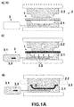
Figure 1A shows a schematic view of steps a), b), c) and d) of the manufacturing procedure for the ceiling trim. -
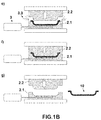
Figure 1A shows a schematic view of steps e), f) and g) of the manufacturing procedure for the ceiling trim. -
Figure 2 shows a view of a detail D shown inFigure 1A that shows the progress of the gas-phase catalyst towards the heat-stable polyurethane adhesive layer. -
Figure 3 shows a schematic view of the mould according to a variant of the invention wherein both the first half of the mould and the second half of the mould comprise means for applying the gas-phase catalyst. -
Figures 4A, 4B and 4C show three "sandwich" layering examples according to the invention. - We shall now detail the sequence of steps shown in
figures 1A and 1B . - The first step, step a) comprises arranging a layer "sandwich" (1) formed by at least one first sheet (1.1) a second coating sheet (1.2) that covers one of the sides of the first sheet (1.1) and a first layer of unactivated heat-stable polyurethane adhesive (1.3) between said at least first sheet (1.1) and said second coating sheet (1.2) in order to join them.
- The term "unactivated" relates to a state of the heat-stable polyurethane adhesive in which the chemical reaction, which results in its curing in a reasonable time corresponding to the usual time cycles in a ceiling trim manufacturing procedure, cannot occur.
- In the particular case of heat-stable polyurethane adhesives contemplated by the invention, it refers to an adhesive to which the corresponding catalyst has not been added, which is a necessary component in order to produce its activation, in a previous step to step b) of introducing the layered sandwich (1) inside the mould (2).
- The following step of the procedure, step b) comprises introducing the sandwich (1) inside a hot thermoforming mould (2) comprising a first half of the mould (2.1) and a second half of the mould (2.2), the temperature of which lies in the range between 100 and 150°C.
- In order to perform the opening and closing movements of said mould (2), at least one of the halves of the mould (2.1, 2.2) can move between a first position in which the halves (2.1, 2.2) of the mould (2) are at a maximum separation, the mould (2) thus being completely open, and a second position in which the mould (2) is completely closed.
- Thus, when the halves (2.1, 2.2) of the mould (2) reach said first position the step of opening the mould (2) would be complete, and when the halves (2.1, 2.2) of the mould (2) reach the second position the step of closing the mould (2) would be completed.
- Once the sandwich (1) in introduced inside a mould (2), step c) of the procedure is carried out, which comprises the application of a gas-phase catalyst (3.3).
- Said gas-phase catalyst (3.3) may be for example, steam, DABCO® (trademark of Air Products & Chemicals), diluted in water as a gas phase, an organometallic compound such as DBTL (dibutyl tin dilaurate) diluted in water as a gas phase or a diluted in water as a gas phase.
- The beginning of this step c) is performed before the completion of step d), which comprises the closing of the mould (2), and the end of step c) is performed before the completion of step e), comprising the opening of the mould (2) to evacuate any excess moisture.
- We must take into account that step d) of closing the mould (2) starts with the beginning of the movement of bringing the two halves (2.1, 2.2) of the mould (2) together and ends when said movement stops, resulting in the closing of the mould (2); and step e) of opening the mould (2) starts when the movement of separating the two halves (2.1, 2.2) of the mould (2) starts and ends when said movement stops, resulting in a completely open mould (2).
- Therefore, the beginning of the application of the gas-phase catalyst can be performed:
- before the start of step d) of closing the mould (2), that is, before the start of the movement of bringing the halves (2.1, 2.2) of the mould (2) together to produce the closing of the mould (2),
- after having started step d) of closing the mould (2), that is, before the start of the movement of bringing the halves (2.1, 2.2) of the mould (2) together to produce the closing of the mould (2),
- or simultaneously at the beginning of step d) of closing the mould (2), that is, when initiating the movement of bringing together the halves (2.1, 2.2) of the mould (2) to produce the closing of the mould (2).
- Regarding the end of the application of the gas-phase catalyst (3.3), this can be performed:
- before the end of step d) of closing the mould (2), that is, during the movement of bringing the halves (2.1, 2.2) of the mould (2) together to produce the closing of the mould (2),
- after the end of step d) of closing the mould (2), that is, once the movement of bringing the halves (2.1, 2.2) of the mould (2) together to produce the closing of the mould (2) is completed,
- after the start of step e) of opening the mould (2) to evacuate any excess moisture, that is, during the movement of separating the two halves (2.1, 2.2) of the mould (2) to produce the opening of the mould (2),
- or simultaneously to any of the last two options, that is, either at the end of the movement of bringing together the two halves (2.1, 2.2) of the mould (2) which produces the closing of the mould (2), or at the beginning of the movement of separating the two halves (2.1, 2.2) of the mould (2) that causes the opening of the mould.
- In order to carry out the application of the gas-phase catalyst (3.3), the mould (2) comprises means (3) for applying the gas-phase catalyst that in turn comprise means (3.1) for generating the gas-phase catalyst (3.3), and conducts (3.2) provided therein that allow transporting the gas-phase catalyst (3.3) from the means (3.1) for generating the gas-phase catalyst to the interior of the mould (2).
- The application of the gas-phase catalyst (3.3) is performed through the first half of the mould (2.1) that is in contact with the second coating sheet (1.2).
- According to a variant of the invention, as shown in
Figure 3 , the application of the gas-phase catalyst (3.3) may also be performed through the second half of the mould (2.2) on a third coating sheet (1.4) that can form part of the sandwich structure (1). - The application of the gas-phase catalyst (3.3) on the sandwich (1) results in the activation of the adhesive forming part of the first heat-stable polyurethane adhesive layer (1.3) as a result of the effect of the gas-phase catalyst (3.3).
- Moreover, said application of the gas-phase catalyst (3.3) is performed with sufficient pressure to allow said gas-phase catalyst (3.3) to access the entire heat-stable polyurethane adhesive and thus allow its activation. Said pressure is greater than the atmospheric pressure and particularly 2 bars, and in a specific case it is in a range between 2 and 15 bar.
- Moreover, the application of the gas-phase catalyst (3.3)results in the creation of a barrier between the first heat-stable polyurethane adhesive layer (1.3) and the surface (2.1.1) forming the first half of the mould (2) as a result of the pressure exerted by the gas-phase catalyst (3.3) on the first layer of heat-stable polyurethane adhesive (1.3).
- Finally, and as shown in detail D represented in
Figure 2 , once the adhesive contained in the first layer of heat-stable polyurethane adhesive (1.3) has been activated, part (1.3.1) of the first layer of heat-stable polyurethane adhesive (1.3) that is in contact with the second coating sheet (1.2) is cured, preventing the adhesive forming said layer (1.3) from passing through to the second coating sheet (1.2), and therefore preventing contact of said adhesive with the surface (2.1.1) of the first half of the mould (2.1). - In the variant shown in
Figure 3 , all these effects produced by applying the gas-phase catalyst through the first half of the mould (2.1) are also produced on a second layer of heat-stable polyurethane adhesive (1.5) that is in contact with a third coating sheet (1.4) which is in contact with the surface (2.2.1) of the second half of the mould (2.2). - This variant therefore contemplates a sandwich the structure of which also consists of a third coating sheet (1.4) joined to the other side of the first sheet (1.1) via a second heat-stable polyurethane adhesive layer (1.5), as shown in the examples represented in Figures 5B and 5C and described in detail below.
- Step d) is then performed, comprising the closing of the thermoforming mould (2) and thus the application of pressure on the sandwich (1). This step d), once step c) is started, is performed by maintaining the introduction of the gas-phase catalyst (3.3) at a pressure of more than 2 bar through the first half of the mould (2.1) and maintaining the circulation of the gas-phase catalyst (3.3) through the sandwich (1).
- Said pressure of the gas-phase catalyst (3.3) results in the discharge thereof from inside the mould (2) as shown in
Figure 1A . - Due to the barrier formed by the curing of a part (1.3.1) of the adhesive corresponding to the heat-stable polyurethane adhesive layer (1.3), said adhesive cannot pass through the second coating sheet (1.2) and therefore cannot reach the surface (2.1.1) corresponding to the first half of the mould (2.1).
- After step d) comes step e), comprising the opening of the mould (2) to evacuate any excess moisture from the sandwich (1) as excess gas in order to prevent the occurrence of moisture in the sandwich (1) as a result of the excess of gas-phase catalyst (3.3) applied thereto.
- Step f) is then performed, comprising closing the mould (2) to complete the curing of the first heat-stable polyurethane adhesive layer (1.3), or of said first heat-stable polyurethane adhesive layer (1.3) and the second heat-stable polyurethane adhesive layer (1.5) according to the variant contemplated in
Figure 3 . - Finally, in order to complete the procedure we have step g), comprising the opening of the mould (2) and the extraction of the ceiling trim (10) with its final shape and all of the cured adhesive.
- Regarding the configuration of the structure of sheets and layers making up the sandwich (1),
Figures 4A, 4B and 4C show three possible embodiments according to the invention. - The first of these represented in
Figure 4A shows a structure formed by a first coating sheet (1.1) and a second coating sheet (1.3) covering one of the sides (1.1.1) of the first sheet (1.1) and a first layer of inactivated heat-stable polyurethane adhesive (1.3). - The first sheet (1.1), as shown in the example represented in
Figure 4C , can also be part of an assembly consisting of several superimposed sheets (1.1, 1.6, 1.7). Particularly, the first sheet (1.1) may comprise a foam sheet, coated on both sides with a sheet of reinforcing fibres (1.6) joined to said foam sheet via a layer of adhesive (1.7). - The second coating sheet (1.2) may comprise a non-decorative coating or a decorative coating.
- The sandwich may also comprise, as shown in
Figure 4B , a third decorative or non-decorative coating sheet (1.4) that covers the other side (1.1.2) of the first sheet (1.1) and a second layer of heat-stable polyurethane adhesive (1.5) between them to join them together.
Claims (6)
- A manufacturing procedure for ceiling trims for vehicles comprising the following steps:a) arranging a layer "sandwich" (1) formed by at least one first sheet (1.1) a second coating sheet (1.2) that covers one of the sides (1.1.1) of the first sheet (1.1) and a first layer of unactivated heat-stable polyurethane adhesive (1.3) between said at least first sheet (1.1) and said second coating sheet (1.2) in order to join them,b) introducing said sandwich (1) inside a hot thermoforming mould (2) comprising a first half of the mould (2.1) and a second half of the mould (2.2), the temperature of which lies in the range between 100 and 150°C,c) applying a gas-phase catalyst (3.3) on the sandwich (1) through the first half of the mould (2.1) that is in contact with the second coating sheet (1.2) with a pressure of more than 2 bar,d) closing the thermoforming mould (2) and thus applying pressure on the sandwich (1),e) opening the mould (2) for the evacuation of any excess moisture in the sandwich (1) as excess gas,f) closing the mould (2) to complete the curing of the first layer of heat-stable polyurethane adhesive,g) opening the mould (2) and extracting the ceiling trim (10),wherein Step c) is started before the end of Step d)
wherein Step c) ends before the end of Step e),
and wherein Step d), once Step c) has started, is performed by maintaining the introduction of the gas-phase catalyst (3.3) at a pressure of more than 2 bar through the first half of the mould (2.1) and maintaining the circulation of the gas-phase catalyst (3.3) through the sandwich (1). - A manufacturing procedure for ceiling trims for vehicles according to Claim 1 wherein the second coating sheet (1.2) is a non-decorative or a decorative coating sheet.
- A manufacturing procedure for ceiling trims for vehicles according to Claim 1 wherein the sandwich (1) comprises a third decorative or non-decorative coating sheet (1.4) that covers the other side (1.1.2) of the first sheet (1.1) and a second layer of heat-stable polyurethane adhesive (1.5) between them to join them together.
- A manufacturing procedure for ceiling trims for vehicles according to Claim 3 wherein the application of the gas-phase catalyst (3) is also performed through the second half of the mould (2.2) in contact with the third decorative or non-decorative coating sheet (1.4).
- A manufacturing procedure for ceiling trims for vehicles according to Claim 1 wherein the first sheet (1.1) is part of an assembly formed by several superimposed sheets (1.1, 1.6, 1.7).
- A manufacturing procedure for ceiling trims for vehicles according to Claim 1 wherein the pressure of the gas-phase catalyst in Steps c) and d) is equal to or less than 15 bar.
Priority Applications (4)
| Application Number | Priority Date | Filing Date | Title |
|---|---|---|---|
| EP16382215.8A EP3246159B1 (en) | 2016-05-17 | 2016-05-17 | Manufacturing procedure for ceiling trims for vehicles |
| ES16382215T ES2747023T3 (en) | 2016-05-17 | 2016-05-17 | Vehicle Roof Trim Manufacturing Process |
| MX2017004696A MX375893B (en) | 2016-05-17 | 2017-04-10 | MANUFACTURING PROCESS FOR ROOF TRIM FOR VEHICLES. |
| US15/596,114 US10632667B2 (en) | 2016-05-17 | 2017-05-16 | Manufacturing procedure for ceiling trims for vehicles |
Applications Claiming Priority (1)
| Application Number | Priority Date | Filing Date | Title |
|---|---|---|---|
| EP16382215.8A EP3246159B1 (en) | 2016-05-17 | 2016-05-17 | Manufacturing procedure for ceiling trims for vehicles |
Publications (2)
| Publication Number | Publication Date |
|---|---|
| EP3246159A1 true EP3246159A1 (en) | 2017-11-22 |
| EP3246159B1 EP3246159B1 (en) | 2019-09-11 |
Family
ID=56137260
Family Applications (1)
| Application Number | Title | Priority Date | Filing Date |
|---|---|---|---|
| EP16382215.8A Active EP3246159B1 (en) | 2016-05-17 | 2016-05-17 | Manufacturing procedure for ceiling trims for vehicles |
Country Status (4)
| Country | Link |
|---|---|
| US (1) | US10632667B2 (en) |
| EP (1) | EP3246159B1 (en) |
| ES (1) | ES2747023T3 (en) |
| MX (1) | MX375893B (en) |
Citations (2)
| Publication number | Priority date | Publication date | Assignee | Title |
|---|---|---|---|---|
| WO2012031190A1 (en) | 2010-09-03 | 2012-03-08 | Cvg Management Corporation | Mold release sheet |
| WO2013111862A1 (en) * | 2012-01-27 | 2013-08-01 | 昭和電工株式会社 | Method for producing master batch for conductive resin, and master batch |
Family Cites Families (13)
| Publication number | Priority date | Publication date | Assignee | Title |
|---|---|---|---|---|
| US3446685A (en) * | 1965-08-13 | 1969-05-27 | Allen Ind | Trim panel and method of making same |
| US4225627A (en) * | 1979-01-08 | 1980-09-30 | A. E. Staley Manufacturing Company | Demolding confections with steam |
| US4526831A (en) * | 1982-06-21 | 1985-07-02 | Edward Hatchadoorian | Process for thermoforming reinforced polymer sheets |
| US5108691A (en) * | 1986-09-03 | 1992-04-28 | Astechnologies, Inc. | Compressing and shaping thermoformable mats using superheated steam |
| US5087311A (en) * | 1986-09-09 | 1992-02-11 | Astechnologies, Inc. | Process of laminating fabric to a concave substrate |
| DE3716479A1 (en) * | 1987-05-16 | 1988-11-24 | Elastogran Gmbh | METHOD FOR PRODUCING COATINGS FROM POLYURETHANE SINGLE-COMPONENT SYSTEMS AND WATER VAPOR |
| US5134014A (en) * | 1991-01-28 | 1992-07-28 | Eften, Inc. | Moldable foam composite |
| US5441675A (en) * | 1993-11-01 | 1995-08-15 | Davidson Textron, Inc. | Forming method and apparatus |
| JP2001047544A (en) * | 1999-08-04 | 2001-02-20 | Sumitomo Bayer Urethane Co Ltd | Manufacture of car interior material of sandwich structure |
| JP4154638B2 (en) * | 1999-11-04 | 2008-09-24 | トヨタ紡織株式会社 | Manufacturing method for interior materials |
| DE102010025169A1 (en) * | 2010-06-25 | 2011-12-29 | C3 Projects Ug | Process for the production of sandwich components |
| DE102013114799A1 (en) * | 2013-12-23 | 2015-06-25 | Kurtz Gmbh | Apparatus and method for producing a particle foam part |
| EP3098058B1 (en) * | 2015-05-25 | 2019-10-30 | Grupo Antolin-Ingenieria, S.A. | Process for manufacturing vehicle headliners |
-
2016
- 2016-05-17 EP EP16382215.8A patent/EP3246159B1/en active Active
- 2016-05-17 ES ES16382215T patent/ES2747023T3/en active Active
-
2017
- 2017-04-10 MX MX2017004696A patent/MX375893B/en active IP Right Grant
- 2017-05-16 US US15/596,114 patent/US10632667B2/en active Active
Patent Citations (2)
| Publication number | Priority date | Publication date | Assignee | Title |
|---|---|---|---|---|
| WO2012031190A1 (en) | 2010-09-03 | 2012-03-08 | Cvg Management Corporation | Mold release sheet |
| WO2013111862A1 (en) * | 2012-01-27 | 2013-08-01 | 昭和電工株式会社 | Method for producing master batch for conductive resin, and master batch |
Also Published As
| Publication number | Publication date |
|---|---|
| EP3246159B1 (en) | 2019-09-11 |
| US20170334102A1 (en) | 2017-11-23 |
| ES2747023T3 (en) | 2020-03-09 |
| MX2017004696A (en) | 2018-08-16 |
| MX375893B (en) | 2025-03-06 |
| US10632667B2 (en) | 2020-04-28 |
Similar Documents
| Publication | Publication Date | Title |
|---|---|---|
| US20170072602A1 (en) | System and method for manufacturing an article | |
| JP5762533B2 (en) | Method for producing components from fiber composites, preforms therefor, and components | |
| EP3911494B1 (en) | Method for the production of motor vehicles and tool suitable therefor | |
| EP3800028B1 (en) | Multi-layered shaped body for internal vehicle fittings and method for producing such shaped bodies | |
| EP0318867A2 (en) | Method and apparatus for laminating composite materials | |
| US20150343717A1 (en) | Method and installation for producing a fiber-reinforced plastic component | |
| EP2321112A1 (en) | Procedure and equipment for making glass frames and glass frame obtained therewith | |
| EP2641839B1 (en) | Methods for manufacturing a shell for a tray packaging | |
| US10821495B2 (en) | Method for producing components for motor-vehicle structures, having a hybrid structure made of light alloy and plastic material | |
| EP3609668B1 (en) | Process for manufacturing a foamed decorated carrierstructure for a vehicle | |
| US10632667B2 (en) | Manufacturing procedure for ceiling trims for vehicles | |
| WO2012130472A1 (en) | Folding method, folding device and component comprising fold | |
| CN104416918B (en) | Method for producing composite material reinforced part | |
| US20090020217A1 (en) | Process for Making Swaged Lighting Holes in Planar Areas of Preimpregnated Composite Parts | |
| DE102007060240A1 (en) | Bonding decoration carrier with decorative material and haptic layer arranged between decoration carrier and decorative material for interior fitting parts in motor vehicles, comprises adhering opposite-lying surfaces by applying coating | |
| CN108527945B (en) | A kind of manufacturing method of the flexible honeycomb of heart cell | |
| WO2023119127A9 (en) | A fibre-metal composite panel comprising a fibre-reinforced thermoplastic panel and a metal plate, and a method for manufacturing it | |
| DE102018212610A1 (en) | Process for producing a multilayer plastic component | |
| US11400628B2 (en) | Method for producing decorative parts | |
| US20160193811A1 (en) | Self-fixturing metallic composite laminate | |
| US9108359B2 (en) | Method for prevention of porosity in composite material parts | |
| DE102011121903A1 (en) | Method for manufacturing three-layered composite component used as e.g. control panel in interior of motor car, involves adheringly connecting injection molded soft foam layer with injection molded carrier by joining step | |
| CA2083736A1 (en) | Method of producing veneer-faced moulded items | |
| EP3865293B1 (en) | Composite material and method of forming composite material | |
| US20200108532A1 (en) | Method For Producing A Cladding Part For Vehicles |
Legal Events
| Date | Code | Title | Description |
|---|---|---|---|
| PUAI | Public reference made under article 153(3) epc to a published international application that has entered the european phase |
Free format text: ORIGINAL CODE: 0009012 |
|
| STAA | Information on the status of an ep patent application or granted ep patent |
Free format text: STATUS: THE APPLICATION HAS BEEN PUBLISHED |
|
| AK | Designated contracting states |
Kind code of ref document: A1 Designated state(s): AL AT BE BG CH CY CZ DE DK EE ES FI FR GB GR HR HU IE IS IT LI LT LU LV MC MK MT NL NO PL PT RO RS SE SI SK SM TR |
|
| AX | Request for extension of the european patent |
Extension state: BA ME |
|
| STAA | Information on the status of an ep patent application or granted ep patent |
Free format text: STATUS: REQUEST FOR EXAMINATION WAS MADE |
|
| 17P | Request for examination filed |
Effective date: 20180518 |
|
| RBV | Designated contracting states (corrected) |
Designated state(s): AL AT BE BG CH CY CZ DE DK EE ES FI FR GB GR HR HU IE IS IT LI LT LU LV MC MK MT NL NO PL PT RO RS SE SI SK SM TR |
|
| GRAP | Despatch of communication of intention to grant a patent |
Free format text: ORIGINAL CODE: EPIDOSNIGR1 |
|
| RIC1 | Information provided on ipc code assigned before grant |
Ipc: B29C 51/14 20060101ALI20190523BHEP Ipc: B32B 37/12 20060101AFI20190523BHEP |
|
| STAA | Information on the status of an ep patent application or granted ep patent |
Free format text: STATUS: GRANT OF PATENT IS INTENDED |
|
| INTG | Intention to grant announced |
Effective date: 20190627 |
|
| GRAS | Grant fee paid |
Free format text: ORIGINAL CODE: EPIDOSNIGR3 |
|
| GRAA | (expected) grant |
Free format text: ORIGINAL CODE: 0009210 |
|
| STAA | Information on the status of an ep patent application or granted ep patent |
Free format text: STATUS: THE PATENT HAS BEEN GRANTED |
|
| AK | Designated contracting states |
Kind code of ref document: B1 Designated state(s): AL AT BE BG CH CY CZ DE DK EE ES FI FR GB GR HR HU IE IS IT LI LT LU LV MC MK MT NL NO PL PT RO RS SE SI SK SM TR |
|
| REG | Reference to a national code |
Ref country code: GB Ref legal event code: FG4D |
|
| REG | Reference to a national code |
Ref country code: CH Ref legal event code: EP |
|
| REG | Reference to a national code |
Ref country code: AT Ref legal event code: REF Ref document number: 1177918 Country of ref document: AT Kind code of ref document: T Effective date: 20190915 |
|
| REG | Reference to a national code |
Ref country code: DE Ref legal event code: R096 Ref document number: 602016020328 Country of ref document: DE Ref country code: IE Ref legal event code: FG4D |
|
| REG | Reference to a national code |
Ref country code: NL Ref legal event code: MP Effective date: 20190911 |
|
| REG | Reference to a national code |
Ref country code: LT Ref legal event code: MG4D |
|
| PG25 | Lapsed in a contracting state [announced via postgrant information from national office to epo] |
Ref country code: NO Free format text: LAPSE BECAUSE OF FAILURE TO SUBMIT A TRANSLATION OF THE DESCRIPTION OR TO PAY THE FEE WITHIN THE PRESCRIBED TIME-LIMIT Effective date: 20191211 Ref country code: BG Free format text: LAPSE BECAUSE OF FAILURE TO SUBMIT A TRANSLATION OF THE DESCRIPTION OR TO PAY THE FEE WITHIN THE PRESCRIBED TIME-LIMIT Effective date: 20191211 Ref country code: LT Free format text: LAPSE BECAUSE OF FAILURE TO SUBMIT A TRANSLATION OF THE DESCRIPTION OR TO PAY THE FEE WITHIN THE PRESCRIBED TIME-LIMIT Effective date: 20190911 Ref country code: HR Free format text: LAPSE BECAUSE OF FAILURE TO SUBMIT A TRANSLATION OF THE DESCRIPTION OR TO PAY THE FEE WITHIN THE PRESCRIBED TIME-LIMIT Effective date: 20190911 Ref country code: FI Free format text: LAPSE BECAUSE OF FAILURE TO SUBMIT A TRANSLATION OF THE DESCRIPTION OR TO PAY THE FEE WITHIN THE PRESCRIBED TIME-LIMIT Effective date: 20190911 Ref country code: SE Free format text: LAPSE BECAUSE OF FAILURE TO SUBMIT A TRANSLATION OF THE DESCRIPTION OR TO PAY THE FEE WITHIN THE PRESCRIBED TIME-LIMIT Effective date: 20190911 |
|
| PG25 | Lapsed in a contracting state [announced via postgrant information from national office to epo] |
Ref country code: AL Free format text: LAPSE BECAUSE OF FAILURE TO SUBMIT A TRANSLATION OF THE DESCRIPTION OR TO PAY THE FEE WITHIN THE PRESCRIBED TIME-LIMIT Effective date: 20190911 Ref country code: GR Free format text: LAPSE BECAUSE OF FAILURE TO SUBMIT A TRANSLATION OF THE DESCRIPTION OR TO PAY THE FEE WITHIN THE PRESCRIBED TIME-LIMIT Effective date: 20191212 Ref country code: RS Free format text: LAPSE BECAUSE OF FAILURE TO SUBMIT A TRANSLATION OF THE DESCRIPTION OR TO PAY THE FEE WITHIN THE PRESCRIBED TIME-LIMIT Effective date: 20190911 Ref country code: LV Free format text: LAPSE BECAUSE OF FAILURE TO SUBMIT A TRANSLATION OF THE DESCRIPTION OR TO PAY THE FEE WITHIN THE PRESCRIBED TIME-LIMIT Effective date: 20190911 |
|
| REG | Reference to a national code |
Ref country code: ES Ref legal event code: FG2A Ref document number: 2747023 Country of ref document: ES Kind code of ref document: T3 Effective date: 20200309 |
|
| REG | Reference to a national code |
Ref country code: AT Ref legal event code: MK05 Ref document number: 1177918 Country of ref document: AT Kind code of ref document: T Effective date: 20190911 |
|
| PG25 | Lapsed in a contracting state [announced via postgrant information from national office to epo] |
Ref country code: RO Free format text: LAPSE BECAUSE OF FAILURE TO SUBMIT A TRANSLATION OF THE DESCRIPTION OR TO PAY THE FEE WITHIN THE PRESCRIBED TIME-LIMIT Effective date: 20190911 Ref country code: IT Free format text: LAPSE BECAUSE OF FAILURE TO SUBMIT A TRANSLATION OF THE DESCRIPTION OR TO PAY THE FEE WITHIN THE PRESCRIBED TIME-LIMIT Effective date: 20190911 Ref country code: NL Free format text: LAPSE BECAUSE OF FAILURE TO SUBMIT A TRANSLATION OF THE DESCRIPTION OR TO PAY THE FEE WITHIN THE PRESCRIBED TIME-LIMIT Effective date: 20190911 Ref country code: PL Free format text: LAPSE BECAUSE OF FAILURE TO SUBMIT A TRANSLATION OF THE DESCRIPTION OR TO PAY THE FEE WITHIN THE PRESCRIBED TIME-LIMIT Effective date: 20190911 Ref country code: EE Free format text: LAPSE BECAUSE OF FAILURE TO SUBMIT A TRANSLATION OF THE DESCRIPTION OR TO PAY THE FEE WITHIN THE PRESCRIBED TIME-LIMIT Effective date: 20190911 Ref country code: AT Free format text: LAPSE BECAUSE OF FAILURE TO SUBMIT A TRANSLATION OF THE DESCRIPTION OR TO PAY THE FEE WITHIN THE PRESCRIBED TIME-LIMIT Effective date: 20190911 Ref country code: PT Free format text: LAPSE BECAUSE OF FAILURE TO SUBMIT A TRANSLATION OF THE DESCRIPTION OR TO PAY THE FEE WITHIN THE PRESCRIBED TIME-LIMIT Effective date: 20200113 |
|
| PG25 | Lapsed in a contracting state [announced via postgrant information from national office to epo] |
Ref country code: CZ Free format text: LAPSE BECAUSE OF FAILURE TO SUBMIT A TRANSLATION OF THE DESCRIPTION OR TO PAY THE FEE WITHIN THE PRESCRIBED TIME-LIMIT Effective date: 20190911 Ref country code: SK Free format text: LAPSE BECAUSE OF FAILURE TO SUBMIT A TRANSLATION OF THE DESCRIPTION OR TO PAY THE FEE WITHIN THE PRESCRIBED TIME-LIMIT Effective date: 20190911 Ref country code: IS Free format text: LAPSE BECAUSE OF FAILURE TO SUBMIT A TRANSLATION OF THE DESCRIPTION OR TO PAY THE FEE WITHIN THE PRESCRIBED TIME-LIMIT Effective date: 20200224 Ref country code: SM Free format text: LAPSE BECAUSE OF FAILURE TO SUBMIT A TRANSLATION OF THE DESCRIPTION OR TO PAY THE FEE WITHIN THE PRESCRIBED TIME-LIMIT Effective date: 20190911 |
|
| REG | Reference to a national code |
Ref country code: DE Ref legal event code: R097 Ref document number: 602016020328 Country of ref document: DE |
|
| REG | Reference to a national code |
Ref country code: DE Ref legal event code: R082 Ref document number: 602016020328 Country of ref document: DE Representative=s name: BRAEUNING & SCHUBERT PATENTANWAELTE GBR, DE Ref country code: DE Ref legal event code: R082 Ref document number: 602016020328 Country of ref document: DE Representative=s name: BRAEUNING & SCHUBERT PATENTANWAELTE, DE Ref country code: DE Ref legal event code: R082 Ref document number: 602016020328 Country of ref document: DE Representative=s name: SCHUBERT, KLEMENS, DIPL.-CHEM. DR.RER.NAT., DE |
|
| PLBE | No opposition filed within time limit |
Free format text: ORIGINAL CODE: 0009261 |
|
| STAA | Information on the status of an ep patent application or granted ep patent |
Free format text: STATUS: NO OPPOSITION FILED WITHIN TIME LIMIT |
|
| PG2D | Information on lapse in contracting state deleted |
Ref country code: IS |
|
| PG25 | Lapsed in a contracting state [announced via postgrant information from national office to epo] |
Ref country code: DK Free format text: LAPSE BECAUSE OF FAILURE TO SUBMIT A TRANSLATION OF THE DESCRIPTION OR TO PAY THE FEE WITHIN THE PRESCRIBED TIME-LIMIT Effective date: 20190911 Ref country code: IS Free format text: LAPSE BECAUSE OF FAILURE TO SUBMIT A TRANSLATION OF THE DESCRIPTION OR TO PAY THE FEE WITHIN THE PRESCRIBED TIME-LIMIT Effective date: 20200112 |
|
| 26N | No opposition filed |
Effective date: 20200615 |
|
| PG25 | Lapsed in a contracting state [announced via postgrant information from national office to epo] |
Ref country code: SI Free format text: LAPSE BECAUSE OF FAILURE TO SUBMIT A TRANSLATION OF THE DESCRIPTION OR TO PAY THE FEE WITHIN THE PRESCRIBED TIME-LIMIT Effective date: 20190911 |
|
| PG25 | Lapsed in a contracting state [announced via postgrant information from national office to epo] |
Ref country code: MC Free format text: LAPSE BECAUSE OF FAILURE TO SUBMIT A TRANSLATION OF THE DESCRIPTION OR TO PAY THE FEE WITHIN THE PRESCRIBED TIME-LIMIT Effective date: 20190911 Ref country code: LI Free format text: LAPSE BECAUSE OF NON-PAYMENT OF DUE FEES Effective date: 20200531 Ref country code: CH Free format text: LAPSE BECAUSE OF NON-PAYMENT OF DUE FEES Effective date: 20200531 |
|
| REG | Reference to a national code |
Ref country code: BE Ref legal event code: MM Effective date: 20200531 |
|
| GBPC | Gb: european patent ceased through non-payment of renewal fee |
Effective date: 20200517 |
|
| PG25 | Lapsed in a contracting state [announced via postgrant information from national office to epo] |
Ref country code: LU Free format text: LAPSE BECAUSE OF NON-PAYMENT OF DUE FEES Effective date: 20200517 |
|
| PG25 | Lapsed in a contracting state [announced via postgrant information from national office to epo] |
Ref country code: GB Free format text: LAPSE BECAUSE OF NON-PAYMENT OF DUE FEES Effective date: 20200517 Ref country code: IE Free format text: LAPSE BECAUSE OF NON-PAYMENT OF DUE FEES Effective date: 20200517 |
|
| PG25 | Lapsed in a contracting state [announced via postgrant information from national office to epo] |
Ref country code: BE Free format text: LAPSE BECAUSE OF NON-PAYMENT OF DUE FEES Effective date: 20200531 |
|
| PG25 | Lapsed in a contracting state [announced via postgrant information from national office to epo] |
Ref country code: TR Free format text: LAPSE BECAUSE OF FAILURE TO SUBMIT A TRANSLATION OF THE DESCRIPTION OR TO PAY THE FEE WITHIN THE PRESCRIBED TIME-LIMIT Effective date: 20190911 Ref country code: MT Free format text: LAPSE BECAUSE OF FAILURE TO SUBMIT A TRANSLATION OF THE DESCRIPTION OR TO PAY THE FEE WITHIN THE PRESCRIBED TIME-LIMIT Effective date: 20190911 Ref country code: CY Free format text: LAPSE BECAUSE OF FAILURE TO SUBMIT A TRANSLATION OF THE DESCRIPTION OR TO PAY THE FEE WITHIN THE PRESCRIBED TIME-LIMIT Effective date: 20190911 |
|
| PG25 | Lapsed in a contracting state [announced via postgrant information from national office to epo] |
Ref country code: MK Free format text: LAPSE BECAUSE OF FAILURE TO SUBMIT A TRANSLATION OF THE DESCRIPTION OR TO PAY THE FEE WITHIN THE PRESCRIBED TIME-LIMIT Effective date: 20190911 |
|
| REG | Reference to a national code |
Ref country code: DE Ref legal event code: R082 Ref document number: 602016020328 Country of ref document: DE Representative=s name: BRAEUNING & SCHUBERT PATENTANWAELTE GBR, DE Ref country code: DE Ref legal event code: R082 Ref document number: 602016020328 Country of ref document: DE Representative=s name: BRAEUNING & SCHUBERT PATENTANWAELTE, DE |
|
| P01 | Opt-out of the competence of the unified patent court (upc) registered |
Effective date: 20230530 |
|
| PGFP | Annual fee paid to national office [announced via postgrant information from national office to epo] |
Ref country code: DE Payment date: 20250526 Year of fee payment: 10 |
|
| PGFP | Annual fee paid to national office [announced via postgrant information from national office to epo] |
Ref country code: ES Payment date: 20250602 Year of fee payment: 10 |
|
| PGFP | Annual fee paid to national office [announced via postgrant information from national office to epo] |
Ref country code: FR Payment date: 20250520 Year of fee payment: 10 |