EP3246124B1 - Befestigung zum halten eines komplex geformten teils während eines bearbeitungsvorgangs - Google Patents
Befestigung zum halten eines komplex geformten teils während eines bearbeitungsvorgangs Download PDFInfo
- Publication number
- EP3246124B1 EP3246124B1 EP17169938.2A EP17169938A EP3246124B1 EP 3246124 B1 EP3246124 B1 EP 3246124B1 EP 17169938 A EP17169938 A EP 17169938A EP 3246124 B1 EP3246124 B1 EP 3246124B1
- Authority
- EP
- European Patent Office
- Prior art keywords
- fixture
- aerofoil
- support
- clamp
- curved surface
- Prior art date
- Legal status (The legal status is an assumption and is not a legal conclusion. Google has not performed a legal analysis and makes no representation as to the accuracy of the status listed.)
- Active
Links
- 238000003754 machining Methods 0.000 title claims description 22
- 239000000463 material Substances 0.000 claims description 5
- 238000000034 method Methods 0.000 description 10
- 230000003044 adaptive effect Effects 0.000 description 3
- 238000005520 cutting process Methods 0.000 description 2
- 238000004519 manufacturing process Methods 0.000 description 2
- 238000003801 milling Methods 0.000 description 2
- 239000011248 coating agent Substances 0.000 description 1
- 238000000576 coating method Methods 0.000 description 1
- 239000002131 composite material Substances 0.000 description 1
- 230000007423 decrease Effects 0.000 description 1
- 230000000694 effects Effects 0.000 description 1
- 239000000446 fuel Substances 0.000 description 1
- 238000000227 grinding Methods 0.000 description 1
- 238000005495 investment casting Methods 0.000 description 1
- 238000005259 measurement Methods 0.000 description 1
- 239000000523 sample Substances 0.000 description 1
Images



Classifications
-
- B—PERFORMING OPERATIONS; TRANSPORTING
- B23—MACHINE TOOLS; METAL-WORKING NOT OTHERWISE PROVIDED FOR
- B23Q—DETAILS, COMPONENTS, OR ACCESSORIES FOR MACHINE TOOLS, e.g. ARRANGEMENTS FOR COPYING OR CONTROLLING; MACHINE TOOLS IN GENERAL CHARACTERISED BY THE CONSTRUCTION OF PARTICULAR DETAILS OR COMPONENTS; COMBINATIONS OR ASSOCIATIONS OF METAL-WORKING MACHINES, NOT DIRECTED TO A PARTICULAR RESULT
- B23Q3/00—Devices holding, supporting, or positioning work or tools, of a kind normally removable from the machine
- B23Q3/02—Devices holding, supporting, or positioning work or tools, of a kind normally removable from the machine for mounting on a work-table, tool-slide, or analogous part
- B23Q3/06—Work-clamping means
- B23Q3/062—Work-clamping means adapted for holding workpieces having a special form or being made from a special material
- B23Q3/063—Work-clamping means adapted for holding workpieces having a special form or being made from a special material for holding turbine blades
-
- B—PERFORMING OPERATIONS; TRANSPORTING
- B23—MACHINE TOOLS; METAL-WORKING NOT OTHERWISE PROVIDED FOR
- B23Q—DETAILS, COMPONENTS, OR ACCESSORIES FOR MACHINE TOOLS, e.g. ARRANGEMENTS FOR COPYING OR CONTROLLING; MACHINE TOOLS IN GENERAL CHARACTERISED BY THE CONSTRUCTION OF PARTICULAR DETAILS OR COMPONENTS; COMBINATIONS OR ASSOCIATIONS OF METAL-WORKING MACHINES, NOT DIRECTED TO A PARTICULAR RESULT
- B23Q3/00—Devices holding, supporting, or positioning work or tools, of a kind normally removable from the machine
-
- F—MECHANICAL ENGINEERING; LIGHTING; HEATING; WEAPONS; BLASTING
- F01—MACHINES OR ENGINES IN GENERAL; ENGINE PLANTS IN GENERAL; STEAM ENGINES
- F01D—NON-POSITIVE DISPLACEMENT MACHINES OR ENGINES, e.g. STEAM TURBINES
- F01D5/00—Blades; Blade-carrying members; Heating, heat-insulating, cooling or antivibration means on the blades or the members
- F01D5/12—Blades
-
- F—MECHANICAL ENGINEERING; LIGHTING; HEATING; WEAPONS; BLASTING
- F05—INDEXING SCHEMES RELATING TO ENGINES OR PUMPS IN VARIOUS SUBCLASSES OF CLASSES F01-F04
- F05D—INDEXING SCHEME FOR ASPECTS RELATING TO NON-POSITIVE-DISPLACEMENT MACHINES OR ENGINES, GAS-TURBINES OR JET-PROPULSION PLANTS
- F05D2230/00—Manufacture
- F05D2230/10—Manufacture by removing material
-
- F—MECHANICAL ENGINEERING; LIGHTING; HEATING; WEAPONS; BLASTING
- F05—INDEXING SCHEMES RELATING TO ENGINES OR PUMPS IN VARIOUS SUBCLASSES OF CLASSES F01-F04
- F05D—INDEXING SCHEME FOR ASPECTS RELATING TO NON-POSITIVE-DISPLACEMENT MACHINES OR ENGINES, GAS-TURBINES OR JET-PROPULSION PLANTS
- F05D2240/00—Components
- F05D2240/20—Rotors
- F05D2240/30—Characteristics of rotor blades, i.e. of any element transforming dynamic fluid energy to or from rotational energy and being attached to a rotor
- F05D2240/304—Characteristics of rotor blades, i.e. of any element transforming dynamic fluid energy to or from rotational energy and being attached to a rotor related to the trailing edge of a rotor blade
Definitions
- the present invention is concerned with accurate machining of surfaces of a complex shaped part, more specifically an aerofoil, in particular a turbine blade. More particularly, the invention is concerned with a fixture for holding such a part securely in position whilst leaving the surface to be machined accessible.
- Turbine aerofoil components are conventionally manufactured by an investment casting process. This process inherently has limits on how thin sections can be cast due to surface tension effects. Typically, the smallest trailing edge thickness which can be reliably cast using the process is around 0.6 mm. To reliably manufacture trailing edge thicknesses of less than 0,6 mm it is desirable to carry out an operation such as machining of the cast component. To preserve the aerodynamic properties of the convex surface of the aerofoil it is further desirable that the material is removed from the concave surface during the thinning operation.
- Fixtures for holding aerofoils during machining processes are known. For example, a 6 point location nest is described in United States patent application publication no. US 2014/191455 A1 . Whilst such arrangements can secure a part, they do not align a trailing edge for accurate machining with respect to the suction surface of the aerofoil. Also, these known arrangements do not provide unencumbered access to a machine tool along the entire length of the trailing edge.
- French patent application FR 2984788 A1 discloses a method of calibrating a turbine blade. The method involves making a first calibration while the blade is held in a coating block and making a second calibration while the blade is held in a support.
- French patent application FR 2976203 A1 discloses a method for machining a composite turbine blade. The method involves using a device that includes vices for holding the blade in position and a mechanism for measuring the profile of the blade.
- the invention seeks to provide a fixture which sets a cast aerofoil in an orientation which is suitable for machining by a direct machining process such as milling.
- the invention provides a fixture and a use of a fixture as set out in the appended claims.
- a fixture for locating a straight edge of a curved surface of an aerofoil, in particular a turbine blade, and holding the aerofoil in a fixed position during performance of a machining operation on a concave side surface adjacent the straight edge of the curved surface of the aerofoil comprising: two or more elongate supports that are spaced apart from each other to form a seat for the convex curved surface of the aerofoil, each elongate support extending straightly and in parallel with a chord of the convex curved surface of the aerofoil; two or more detachable end stops arranged to extend in a plane orthogonal to that in which the elongate supports extend and against which, in use, the straight edge of the curved surface of the aerofoil is aligned; and a clamp; the clamp being arranged, in use, to push the convex curved surface of the aerofoil against the elongate supports such that the straight edge
- a convex surface of the aerofoil is laid against the elongate supports and tilted such that the straight edge lies against the elongate support(s).
- the detachable end stops are positioned in the orthogonal plane and the straight edge is slid along the elongate support until the straight edge is aligned with the end stops. With the straight edge in the desired position, the clamp is applied to hold the aerofoil in the desired position.
- the detachable end stops may then be removed exposing the concave side edge surface for machining.
- the detachable end stop may comprise a flat plate.
- the end stop comprises two or more spaced apart rods.
- the rods may have a rounded cross section.
- the rods may present an angled edge to the straight edge of the aerofoil.
- the rods may present a narrow flat surface to the straight edge.
- the fixture may further comprise a convex surface counter-support for countering any undesirable load from the clamp which may cause slippage and/or tilting of the aerofoil after it has been positioned.
- the counter support may, for example, comprise a wedge or a bar whose position is slidably adjustable to accommodate various degrees of curvature.
- the counter-support may comprise part of the clamp.
- the counter-support may comprise part of the support.
- the clamp and the counter support may comprise a pivoted clamp.
- the fixture may further comprise one or more additional stops arranged in a third plane orthogonal to both the plane in which the support(s) sits, to control the location of the blade in the direction of which the detachable end stops extend
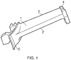
- the blade of Figure 1 has a concave surface 1 on an opposite face to a convex surface 2.
- the two surfaces 1, 2 meet at a trailing edge 3.
- the blade has a tip platform 4 and a root platform 5.
- Figure 2 shows the blade of Figure 1 in the process of having a surface of the trailing edge 3a machined by a tool 6.
- the machine tool 6 may be of a milling or grinding machine.
- Figure 3 shows the blade of Figure 1 arranged in a fixture according to an embodiment of the invention.
- the fixture comprises a pair of support bars 10a, 10b onto which the convex surface 2 of the blade is seated.
- Extending in an orthogonal plane is a pair of detachable end stops in the form of rods 11.
- the trailing edge 3 of the blade is aligned against the end stops 11.
- the convex surface 2 adjacent the trailing edge 3 is positioned flat against the supports 10a, 10b. This may be facilitated by means of a pivoted convex surface support 12.
- the tooling may further include a stop 13 in a third orthogonal direction against which the tip platform is aligned. In alternatives, the position of this stop could be on the opposite face of the tip platform 4, or on either face of the root platform 5.
- the stop 13 may be fixedly connected to a frame which also comprises the support bars 10a, 10b.
- the centrally pivoted clamp 14 is located approximately 1/3 of the way along the chordal length of the blade from the trailing edge 3 to the leading edge.
- This clamp 14 acts on the concave surface to force the aerofoil firmly against the supports 10a, 10b and the centrally pivoted counter-support 12, but without excessive force so as to cause distortion of the trailing edge.
- the blade is thus firmly gripped as a result of the reactionary forces from the clamp 14, the supports 10a, 10b and the centrally pivoted convex support 12.
- the trailing edge end stops 11 can now be retracted (e.g. vertically) away from the remainder of the tooling to allow access for the cutting tool 6 as shown in Figures 2 and 6 .
- the detail of the tooling design will depend on the specific geometry of the aerofoil to be machined, and in particular the relative distances and angles between the clamp 14 and the counter-support 12 and the trailing edge supports 10a and 10b, to ensure that the aerofoil is held firmly in position during the machining operation.
- the trailing edge 3 can be machined along the concave surface side of the trailing edge to form the desired thinner trailing edge profile.
- a measurement process such as a scanning probe or a laser system, may be used to measure the trailing edge thickness from the tip platform 4 to the root platform 5, or visa-versa, to make allowances for any part distortion, such as trailing edge bow, during the machining operation.
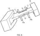
- the tip and root platforms 4, 5 of the blade are supported in compliant gripping fixtures 15, 16.
- the compliant gripping fixtures may be rotated and locked into position once the convex surface adjacent the trailing edge is in contact with the support bars 10a, 10b and the detachable end stops 11.
- the clamp 14 (which in this embodiment is positioned closer to the trailing edge 3) pushes the convex surface intimately against the supports 10a, 10b. With the blade properly positioned for subsequent machining, the compliant gripping fixtures 15, 16 are locked to maintain the position and the clamp 14 can be removed providing access to the concave side trailing edge for machining.
- the clamp 14 can be dispensed with once compliant gripping fixtures 15, 16 have been locked in position.
- the clamp 14 is arranged such that there is negligible force in a plane parallel to the support bars 10a, 10b.
- the position of the blade can be maintained whilst compliant gripping fixtures 15, 16 are locked in position.
- the centrally pivoted clamp 14 is positioned much closer to the apex of the trailing edge 3. This allows the trailing edge to be located more intimately against the supports 10a, 10b, thereby improving the accuracy of the setting and thus the final profile of the trailing edge. With this arrangement, the blade is clamped in position after it has been appropriately positioned and oriented.
- the compliant gripping fixtures 15, 16 can be arranged to hold a platform 4, 5 of the blade in a given orientation. Once the blade and compliant gripping fixtures 15, 16 are in the desired position and orientation, the ends of the fixtures 15, 16 are firmly clamped.
- the end stops 11 and clamp 14 are retracted away from the trailing edge 3 to allow access for the cutting tool 6 to machine the trailing edge 3.
- the material removal 17 is carried out relative to the datum system of the tool, in particular the supports 10a, 10b and the position of the trailing edge end stops 11 (prior to their removal).
Landscapes
- Engineering & Computer Science (AREA)
- Mechanical Engineering (AREA)
- General Engineering & Computer Science (AREA)
- Jigs For Machine Tools (AREA)
- Surgical Instruments (AREA)
Claims (11)
- Befestigung zum Positionieren einer geraden Kante (3) einer gekrümmten Oberfläche (2) eines Leitflügels, insbesondere eines Turbinenflügels, und Halten des Leitflügels in einer festen Position während der Ausführung von Maschinenbearbeitung an einer konkaven Seitenfläche, angrenzend an die gerade Kante der gekrümmten Oberfläche des Leitflügels, wobei die Befestigung umfasst:zwei oder oder mehr längliche Stützen (10a, 10b), die voneinander beabstandet sind, um einen Sitz für die konvexe gekrümmte Oberfläche (2) des Leitflügels zu formen, wobei jede längliche Stütze (10a, 10b) gerade und parallel zu einer Flügeltiefe der konvexen gekrümmten Oberfläche (2) des Leitflügels verläuft;zwei oder mehrere abnehmbare Endanschläge (11), die angeordnet sind, um in einer Ebene zu verlaufen, die rechtwinklig zu der ist, in der die länglichen Stützen (10a, 10b) verlaufen und auf die, in Gebrauch, die gerade Kante (3) der gekrümmten Oberfläche (2) des Leitflügels ausgerichtet ist;und eine Klemme (14);wobei die Klemme, in Gebrauch, angeordnet ist, um die konvexe gekrümmte Oberfläche (2) des Leitflügels gegen die länglichen Stützen (10a, 10b) zu drücken, so dass die gerade Kante (3) der gekrümmten Oberfläche (2) des Leitflügels die länglichen Stützen (10a, 10b) kontaktiert und nach dem Entfernen der abnehmbaren Endanschläge (11) die konkave Seitenfläche angrenzend an die gerade Kante (3) zur Maschinenbearbeitung freigelegt ist.
- Befestigung nach Anspruch 1, wobei jede längliche Stütze (10a, 10b) einen abgerundeten Querschnitt aufweist.
- Befestigung nach Anspruch 1 oder 2, wobei jeder abnehmbare Endanschlag (11) zwei oder mehrere beabstandete Stangen umfasst.
- Befestigung nach Anspruch 3, wobei jede Stange einen abgerundeten Querschnitt aufweist.
- Befestigung nach einem der vorstehenden Ansprüche, wobei die Klemme (14) eine schwenkbare Klemme umfasst.
- Befestigung nach einem der vorstehenden Ansprüche, ferner umfassend eine konvexe Oberflächen-Konterstütze (12) zum Kontern von unerwünschten Lasten von der Klemme (14), die zu Gleiten und/oder Kippen des Teils nach seiner Positionierung führen können.
- Befestigung nach Anspruch 6, wobei die konvexe Oberflächen-Konterstütze (12) einen Keil oder einen Balken umfasst, dessen Position gleitbar eingestellt werden kann, um unterschiedlichen Krümmungsgraden Rechnung zu tragen.
- Befestigung nach Anspruch 6, wobei die konvexe Oberflächen-Konterstütze (12) eine schwenkbare Stütze umfasst.
- Befestigung nach einem der vorstehenden Ansprüche, ferner umfassend einen oder mehrere zusätzliche Anschläge (13), die in einer Ebene angeordnet sind, die rechtwinklig zu der Ebene, in der jede längliche Stütze (10a, 10b) sitzt, und zu der Ebene, in der die abnehmbaren Endanschläge (11) verlaufen, ist.
- Befestigung nach einem der Ansprüche 1 bis 5, ferner umfassend ein Paar nachgiebige Greifbefestigungen (15, 16), die konfiguriert sind, um gegenüberliegende Enden des Teils auf eine Art und Weise aufzunehmen, die nicht zulässt, dass das Teil relativ zum Paar nachgiebiger Greifbefestigungen (15, 16) rotiert.
- Verwendung einer Befestigung nach einem der vorstehenden Ansprüche, um einen Leitflügel so auszurichten, dass seine Hinterkante (3) für ein Maschinenwerkzeug zugänglich ist, und Ausführen eines Maschinenbearbeitungsvorgangs mit dem Maschinenwerkzeug, um Material von der Hinterkante an einer konkaven Oberflächenseite des Leitflügels zu entfernen.
Applications Claiming Priority (1)
| Application Number | Priority Date | Filing Date | Title |
|---|---|---|---|
| GBGB1608639.9A GB201608639D0 (en) | 2016-05-17 | 2016-05-17 | Fixture for holding a complex-shaped part during a machining operation |
Publications (2)
| Publication Number | Publication Date |
|---|---|
| EP3246124A1 EP3246124A1 (de) | 2017-11-22 |
| EP3246124B1 true EP3246124B1 (de) | 2019-07-10 |
Family
ID=56320520
Family Applications (1)
| Application Number | Title | Priority Date | Filing Date |
|---|---|---|---|
| EP17169938.2A Active EP3246124B1 (de) | 2016-05-17 | 2017-05-08 | Befestigung zum halten eines komplex geformten teils während eines bearbeitungsvorgangs |
Country Status (4)
| Country | Link |
|---|---|
| US (1) | US10589392B2 (de) |
| EP (1) | EP3246124B1 (de) |
| CN (2) | CN207014030U (de) |
| GB (1) | GB201608639D0 (de) |
Families Citing this family (2)
| Publication number | Priority date | Publication date | Assignee | Title |
|---|---|---|---|---|
| CN113664568B (zh) * | 2021-09-29 | 2022-07-19 | 中国航发动力股份有限公司 | 一种测量工装及坐标系建立方法 |
| US12109622B1 (en) | 2023-03-14 | 2024-10-08 | Rtx Corporation | Spindles peening offset fixture for CNC turning |
Family Cites Families (17)
| Publication number | Priority date | Publication date | Assignee | Title |
|---|---|---|---|---|
| US3827965A (en) * | 1973-02-02 | 1974-08-06 | United Aircraft Corp | Electrochemical drilling apparatus |
| US5168608A (en) * | 1990-01-10 | 1992-12-08 | Refurbished Turbine Components Limited | Apparatus for the repair of turbine blades |
| GB9000580D0 (en) | 1990-01-10 | 1990-03-14 | Refurbished Turbine Components | Apparatus for and methods of the repair of turbine blades |
| US5954464A (en) | 1997-09-05 | 1999-09-21 | United Technologies Corporation | Method for forming the edge of an airfoil |
| TW487617B (en) * | 2000-08-04 | 2002-05-21 | Smc Kk | Clamp apparatus |
| EP1935558A1 (de) * | 2006-12-19 | 2008-06-25 | Pilkington Italia S.p.A. | System und Verfahren zur Herstellung rahmenloser Fenster |
| CN101372046B (zh) * | 2008-09-26 | 2011-02-02 | 无锡透平叶片有限公司 | 叶片用钻叶顶中心孔的专用夹具 |
| CN101804609B (zh) * | 2010-03-23 | 2011-10-12 | 山东潍坊福田模具有限责任公司 | 异形零件机加工快速装夹装置 |
| CN102145464B (zh) * | 2010-11-20 | 2013-01-23 | 无锡透平叶片有限公司 | 用于菌型叶片叶冠加工的定位装夹装置 |
| GB201102799D0 (en) | 2011-02-18 | 2011-04-06 | Rolls Royce Plc | Apparatus for immobilising a component during a machining operation |
| FR2976203B1 (fr) * | 2011-06-07 | 2017-01-06 | Snecma | Procede d'usinage d'une aube composite |
| FR2976836B1 (fr) | 2011-06-21 | 2013-06-21 | Snecma | Dispositif de maintien d'une aube de turbomachine en vue d'un usinage |
| FR2984788B1 (fr) * | 2011-12-23 | 2014-08-29 | Snecma | Support pour aube de turbomachine |
| GB2505496A (en) | 2012-09-03 | 2014-03-05 | Rolls Royce Plc | Fixture and method for securing an aerofoil |
| US9719356B2 (en) | 2013-06-21 | 2017-08-01 | Rolls-Royce Plc | Method of finishing a blade |
| CN203973245U (zh) * | 2014-08-25 | 2014-12-03 | 哈尔滨汽轮机厂有限责任公司 | 一种铣床用于加工燃压导叶片铣销钉的叶片定位装置 |
| CN105415038B (zh) * | 2015-12-31 | 2018-08-24 | 无锡透平叶片有限公司 | 用于汽轮机静叶片总长线切割的夹具 |
-
2016
- 2016-05-17 GB GBGB1608639.9A patent/GB201608639D0/en not_active Ceased
-
2017
- 2017-05-08 US US15/589,179 patent/US10589392B2/en not_active Expired - Fee Related
- 2017-05-08 EP EP17169938.2A patent/EP3246124B1/de active Active
- 2017-05-17 CN CN201720547603.2U patent/CN207014030U/zh not_active Expired - Fee Related
- 2017-05-17 CN CN201710347942.0A patent/CN107378542B/zh not_active Expired - Fee Related
Non-Patent Citations (1)
| Title |
|---|
| None * |
Also Published As
| Publication number | Publication date |
|---|---|
| US10589392B2 (en) | 2020-03-17 |
| US20170334029A1 (en) | 2017-11-23 |
| GB201608639D0 (en) | 2016-06-29 |
| CN107378542B (zh) | 2021-03-16 |
| CN207014030U (zh) | 2018-02-16 |
| EP3246124A1 (de) | 2017-11-22 |
| CN107378542A (zh) | 2017-11-24 |
Similar Documents
| Publication | Publication Date | Title |
|---|---|---|
| US3818646A (en) | Fixture for holding precisely shaped parts | |
| US9511469B2 (en) | Polishing assembly and method for polishing using a platform and barrier in a tumbling process | |
| US20030114082A1 (en) | Fixture for clamping a gas turbine component and its use in shaping the gas turbine component | |
| US20100005637A1 (en) | Turbine Element Repair Fixture | |
| US10589392B2 (en) | Fixture for holding a complex-shaped part during a machining operation | |
| EP3257622B1 (de) | Halterung zum halten eines teils während eines bearbeitungsvorgangs | |
| US6855033B2 (en) | Fixture for clamping a gas turbine component blank and its use in shaping the gas turbine component blank | |
| EP1319473B1 (de) | Spannvorrichtung zur Befestigung eines Bauteils einer Gasturbine und deren Anwendung in die Formgebung | |
| US10556310B2 (en) | Method for cutting machining of turbine blades | |
| CN205096893U (zh) | 燕尾榫头叶片铣加工叶型用夹具 | |
| US3963894A (en) | Turbine-nozzle manufacturing apparatus | |
| US7109436B2 (en) | Laser shock peening target | |
| GB2533971A (en) | Method and apparatus for machining a blade | |
| JP2003508234A (ja) | 締付け装置を持つ工作機械 | |
| US11703281B2 (en) | Vacuum forming method | |
| GB2625455A (en) | Device and method for milling of complex grid-type ribbed member by precise machining allowance | |
| CN120734401B (zh) | 纵树型叶根式叶片前序加工方法及夹具 | |
| US11454123B2 (en) | Method for machining free-form surface on elongated material | |
| CN112743372B (zh) | 一种涡轮叶片拉筋孔加工用定位量棒及其加工、使用方法 | |
| JP2020131331A (ja) | ブレード把持治具 | |
| CN117450967A (zh) | 一种涡轮叶片六点定位检测方法 |
Legal Events
| Date | Code | Title | Description |
|---|---|---|---|
| PUAI | Public reference made under article 153(3) epc to a published international application that has entered the european phase |
Free format text: ORIGINAL CODE: 0009012 |
|
| STAA | Information on the status of an ep patent application or granted ep patent |
Free format text: STATUS: THE APPLICATION HAS BEEN PUBLISHED |
|
| AK | Designated contracting states |
Kind code of ref document: A1 Designated state(s): AL AT BE BG CH CY CZ DE DK EE ES FI FR GB GR HR HU IE IS IT LI LT LU LV MC MK MT NL NO PL PT RO RS SE SI SK SM TR |
|
| AX | Request for extension of the european patent |
Extension state: BA ME |
|
| STAA | Information on the status of an ep patent application or granted ep patent |
Free format text: STATUS: REQUEST FOR EXAMINATION WAS MADE |
|
| 17P | Request for examination filed |
Effective date: 20180522 |
|
| RBV | Designated contracting states (corrected) |
Designated state(s): AL AT BE BG CH CY CZ DE DK EE ES FI FR GB GR HR HU IE IS IT LI LT LU LV MC MK MT NL NO PL PT RO RS SE SI SK SM TR |
|
| GRAP | Despatch of communication of intention to grant a patent |
Free format text: ORIGINAL CODE: EPIDOSNIGR1 |
|
| STAA | Information on the status of an ep patent application or granted ep patent |
Free format text: STATUS: GRANT OF PATENT IS INTENDED |
|
| GRAJ | Information related to disapproval of communication of intention to grant by the applicant or resumption of examination proceedings by the epo deleted |
Free format text: ORIGINAL CODE: EPIDOSDIGR1 |
|
| STAA | Information on the status of an ep patent application or granted ep patent |
Free format text: STATUS: REQUEST FOR EXAMINATION WAS MADE |
|
| GRAP | Despatch of communication of intention to grant a patent |
Free format text: ORIGINAL CODE: EPIDOSNIGR1 |
|
| STAA | Information on the status of an ep patent application or granted ep patent |
Free format text: STATUS: GRANT OF PATENT IS INTENDED |
|
| INTG | Intention to grant announced |
Effective date: 20190318 |
|
| INTC | Intention to grant announced (deleted) | ||
| GRAS | Grant fee paid |
Free format text: ORIGINAL CODE: EPIDOSNIGR3 |
|
| INTG | Intention to grant announced |
Effective date: 20190415 |
|
| GRAA | (expected) grant |
Free format text: ORIGINAL CODE: 0009210 |
|
| STAA | Information on the status of an ep patent application or granted ep patent |
Free format text: STATUS: THE PATENT HAS BEEN GRANTED |
|
| AK | Designated contracting states |
Kind code of ref document: B1 Designated state(s): AL AT BE BG CH CY CZ DE DK EE ES FI FR GB GR HR HU IE IS IT LI LT LU LV MC MK MT NL NO PL PT RO RS SE SI SK SM TR |
|
| REG | Reference to a national code |
Ref country code: GB Ref legal event code: FG4D |
|
| REG | Reference to a national code |
Ref country code: CH Ref legal event code: EP Ref country code: AT Ref legal event code: REF Ref document number: 1153013 Country of ref document: AT Kind code of ref document: T Effective date: 20190715 |
|
| REG | Reference to a national code |
Ref country code: DE Ref legal event code: R096 Ref document number: 602017005118 Country of ref document: DE |
|
| REG | Reference to a national code |
Ref country code: IE Ref legal event code: FG4D |
|
| REG | Reference to a national code |
Ref country code: NL Ref legal event code: MP Effective date: 20190710 |
|
| REG | Reference to a national code |
Ref country code: LT Ref legal event code: MG4D |
|
| REG | Reference to a national code |
Ref country code: AT Ref legal event code: MK05 Ref document number: 1153013 Country of ref document: AT Kind code of ref document: T Effective date: 20190710 |
|
| PG25 | Lapsed in a contracting state [announced via postgrant information from national office to epo] |
Ref country code: NO Free format text: LAPSE BECAUSE OF FAILURE TO SUBMIT A TRANSLATION OF THE DESCRIPTION OR TO PAY THE FEE WITHIN THE PRESCRIBED TIME-LIMIT Effective date: 20191010 Ref country code: BG Free format text: LAPSE BECAUSE OF FAILURE TO SUBMIT A TRANSLATION OF THE DESCRIPTION OR TO PAY THE FEE WITHIN THE PRESCRIBED TIME-LIMIT Effective date: 20191010 Ref country code: SE Free format text: LAPSE BECAUSE OF FAILURE TO SUBMIT A TRANSLATION OF THE DESCRIPTION OR TO PAY THE FEE WITHIN THE PRESCRIBED TIME-LIMIT Effective date: 20190710 Ref country code: AT Free format text: LAPSE BECAUSE OF FAILURE TO SUBMIT A TRANSLATION OF THE DESCRIPTION OR TO PAY THE FEE WITHIN THE PRESCRIBED TIME-LIMIT Effective date: 20190710 Ref country code: HR Free format text: LAPSE BECAUSE OF FAILURE TO SUBMIT A TRANSLATION OF THE DESCRIPTION OR TO PAY THE FEE WITHIN THE PRESCRIBED TIME-LIMIT Effective date: 20190710 Ref country code: LT Free format text: LAPSE BECAUSE OF FAILURE TO SUBMIT A TRANSLATION OF THE DESCRIPTION OR TO PAY THE FEE WITHIN THE PRESCRIBED TIME-LIMIT Effective date: 20190710 Ref country code: PT Free format text: LAPSE BECAUSE OF FAILURE TO SUBMIT A TRANSLATION OF THE DESCRIPTION OR TO PAY THE FEE WITHIN THE PRESCRIBED TIME-LIMIT Effective date: 20191111 Ref country code: NL Free format text: LAPSE BECAUSE OF FAILURE TO SUBMIT A TRANSLATION OF THE DESCRIPTION OR TO PAY THE FEE WITHIN THE PRESCRIBED TIME-LIMIT Effective date: 20190710 Ref country code: FI Free format text: LAPSE BECAUSE OF FAILURE TO SUBMIT A TRANSLATION OF THE DESCRIPTION OR TO PAY THE FEE WITHIN THE PRESCRIBED TIME-LIMIT Effective date: 20190710 |
|
| RAP2 | Party data changed (patent owner data changed or rights of a patent transferred) |
Owner name: ROLLS-ROYCE PLC |
|
| PG25 | Lapsed in a contracting state [announced via postgrant information from national office to epo] |
Ref country code: ES Free format text: LAPSE BECAUSE OF FAILURE TO SUBMIT A TRANSLATION OF THE DESCRIPTION OR TO PAY THE FEE WITHIN THE PRESCRIBED TIME-LIMIT Effective date: 20190710 Ref country code: GR Free format text: LAPSE BECAUSE OF FAILURE TO SUBMIT A TRANSLATION OF THE DESCRIPTION OR TO PAY THE FEE WITHIN THE PRESCRIBED TIME-LIMIT Effective date: 20191011 Ref country code: RS Free format text: LAPSE BECAUSE OF FAILURE TO SUBMIT A TRANSLATION OF THE DESCRIPTION OR TO PAY THE FEE WITHIN THE PRESCRIBED TIME-LIMIT Effective date: 20190710 Ref country code: IS Free format text: LAPSE BECAUSE OF FAILURE TO SUBMIT A TRANSLATION OF THE DESCRIPTION OR TO PAY THE FEE WITHIN THE PRESCRIBED TIME-LIMIT Effective date: 20191110 Ref country code: AL Free format text: LAPSE BECAUSE OF FAILURE TO SUBMIT A TRANSLATION OF THE DESCRIPTION OR TO PAY THE FEE WITHIN THE PRESCRIBED TIME-LIMIT Effective date: 20190710 Ref country code: LV Free format text: LAPSE BECAUSE OF FAILURE TO SUBMIT A TRANSLATION OF THE DESCRIPTION OR TO PAY THE FEE WITHIN THE PRESCRIBED TIME-LIMIT Effective date: 20190710 |
|
| PG25 | Lapsed in a contracting state [announced via postgrant information from national office to epo] |
Ref country code: TR Free format text: LAPSE BECAUSE OF FAILURE TO SUBMIT A TRANSLATION OF THE DESCRIPTION OR TO PAY THE FEE WITHIN THE PRESCRIBED TIME-LIMIT Effective date: 20190710 |
|
| PG25 | Lapsed in a contracting state [announced via postgrant information from national office to epo] |
Ref country code: IT Free format text: LAPSE BECAUSE OF FAILURE TO SUBMIT A TRANSLATION OF THE DESCRIPTION OR TO PAY THE FEE WITHIN THE PRESCRIBED TIME-LIMIT Effective date: 20190710 Ref country code: RO Free format text: LAPSE BECAUSE OF FAILURE TO SUBMIT A TRANSLATION OF THE DESCRIPTION OR TO PAY THE FEE WITHIN THE PRESCRIBED TIME-LIMIT Effective date: 20190710 Ref country code: DK Free format text: LAPSE BECAUSE OF FAILURE TO SUBMIT A TRANSLATION OF THE DESCRIPTION OR TO PAY THE FEE WITHIN THE PRESCRIBED TIME-LIMIT Effective date: 20190710 Ref country code: EE Free format text: LAPSE BECAUSE OF FAILURE TO SUBMIT A TRANSLATION OF THE DESCRIPTION OR TO PAY THE FEE WITHIN THE PRESCRIBED TIME-LIMIT Effective date: 20190710 Ref country code: PL Free format text: LAPSE BECAUSE OF FAILURE TO SUBMIT A TRANSLATION OF THE DESCRIPTION OR TO PAY THE FEE WITHIN THE PRESCRIBED TIME-LIMIT Effective date: 20190710 |
|
| PG25 | Lapsed in a contracting state [announced via postgrant information from national office to epo] |
Ref country code: IS Free format text: LAPSE BECAUSE OF FAILURE TO SUBMIT A TRANSLATION OF THE DESCRIPTION OR TO PAY THE FEE WITHIN THE PRESCRIBED TIME-LIMIT Effective date: 20200224 Ref country code: SK Free format text: LAPSE BECAUSE OF FAILURE TO SUBMIT A TRANSLATION OF THE DESCRIPTION OR TO PAY THE FEE WITHIN THE PRESCRIBED TIME-LIMIT Effective date: 20190710 Ref country code: SM Free format text: LAPSE BECAUSE OF FAILURE TO SUBMIT A TRANSLATION OF THE DESCRIPTION OR TO PAY THE FEE WITHIN THE PRESCRIBED TIME-LIMIT Effective date: 20190710 Ref country code: CZ Free format text: LAPSE BECAUSE OF FAILURE TO SUBMIT A TRANSLATION OF THE DESCRIPTION OR TO PAY THE FEE WITHIN THE PRESCRIBED TIME-LIMIT Effective date: 20190710 |
|
| REG | Reference to a national code |
Ref country code: DE Ref legal event code: R097 Ref document number: 602017005118 Country of ref document: DE |
|
| PLBE | No opposition filed within time limit |
Free format text: ORIGINAL CODE: 0009261 |
|
| STAA | Information on the status of an ep patent application or granted ep patent |
Free format text: STATUS: NO OPPOSITION FILED WITHIN TIME LIMIT |
|
| PG2D | Information on lapse in contracting state deleted |
Ref country code: IS |
|
| 26N | No opposition filed |
Effective date: 20200603 |
|
| PG25 | Lapsed in a contracting state [announced via postgrant information from national office to epo] |
Ref country code: SI Free format text: LAPSE BECAUSE OF FAILURE TO SUBMIT A TRANSLATION OF THE DESCRIPTION OR TO PAY THE FEE WITHIN THE PRESCRIBED TIME-LIMIT Effective date: 20190710 |
|
| REG | Reference to a national code |
Ref country code: DE Ref legal event code: R119 Ref document number: 602017005118 Country of ref document: DE |
|
| PG25 | Lapsed in a contracting state [announced via postgrant information from national office to epo] |
Ref country code: CH Free format text: LAPSE BECAUSE OF NON-PAYMENT OF DUE FEES Effective date: 20200531 Ref country code: LI Free format text: LAPSE BECAUSE OF NON-PAYMENT OF DUE FEES Effective date: 20200531 Ref country code: MC Free format text: LAPSE BECAUSE OF FAILURE TO SUBMIT A TRANSLATION OF THE DESCRIPTION OR TO PAY THE FEE WITHIN THE PRESCRIBED TIME-LIMIT Effective date: 20190710 |
|
| REG | Reference to a national code |
Ref country code: BE Ref legal event code: MM Effective date: 20200531 |
|
| PG25 | Lapsed in a contracting state [announced via postgrant information from national office to epo] |
Ref country code: LU Free format text: LAPSE BECAUSE OF NON-PAYMENT OF DUE FEES Effective date: 20200508 |
|
| PG25 | Lapsed in a contracting state [announced via postgrant information from national office to epo] |
Ref country code: IE Free format text: LAPSE BECAUSE OF NON-PAYMENT OF DUE FEES Effective date: 20200508 Ref country code: FR Free format text: LAPSE BECAUSE OF NON-PAYMENT OF DUE FEES Effective date: 20200531 |
|
| PG25 | Lapsed in a contracting state [announced via postgrant information from national office to epo] |
Ref country code: BE Free format text: LAPSE BECAUSE OF NON-PAYMENT OF DUE FEES Effective date: 20200531 Ref country code: DE Free format text: LAPSE BECAUSE OF NON-PAYMENT OF DUE FEES Effective date: 20201201 |
|
| GBPC | Gb: european patent ceased through non-payment of renewal fee |
Effective date: 20210508 |
|
| PG25 | Lapsed in a contracting state [announced via postgrant information from national office to epo] |
Ref country code: GB Free format text: LAPSE BECAUSE OF NON-PAYMENT OF DUE FEES Effective date: 20210508 |
|
| PG25 | Lapsed in a contracting state [announced via postgrant information from national office to epo] |
Ref country code: MT Free format text: LAPSE BECAUSE OF FAILURE TO SUBMIT A TRANSLATION OF THE DESCRIPTION OR TO PAY THE FEE WITHIN THE PRESCRIBED TIME-LIMIT Effective date: 20190710 Ref country code: CY Free format text: LAPSE BECAUSE OF FAILURE TO SUBMIT A TRANSLATION OF THE DESCRIPTION OR TO PAY THE FEE WITHIN THE PRESCRIBED TIME-LIMIT Effective date: 20190710 |
|
| PG25 | Lapsed in a contracting state [announced via postgrant information from national office to epo] |
Ref country code: MK Free format text: LAPSE BECAUSE OF FAILURE TO SUBMIT A TRANSLATION OF THE DESCRIPTION OR TO PAY THE FEE WITHIN THE PRESCRIBED TIME-LIMIT Effective date: 20190710 |