EP3246124A1 - Fixture for holding a complex-shaped part during a machining operation - Google Patents
Fixture for holding a complex-shaped part during a machining operation Download PDFInfo
- Publication number
- EP3246124A1 EP3246124A1 EP17169938.2A EP17169938A EP3246124A1 EP 3246124 A1 EP3246124 A1 EP 3246124A1 EP 17169938 A EP17169938 A EP 17169938A EP 3246124 A1 EP3246124 A1 EP 3246124A1
- Authority
- EP
- European Patent Office
- Prior art keywords
- fixture
- support
- clamp
- supports
- straight edge
- Prior art date
- Legal status (The legal status is an assumption and is not a legal conclusion. Google has not performed a legal analysis and makes no representation as to the accuracy of the status listed.)
- Granted
Links
- 238000003754 machining Methods 0.000 title claims abstract description 21
- 239000000463 material Substances 0.000 claims description 5
- 238000000034 method Methods 0.000 description 6
- 230000003044 adaptive effect Effects 0.000 description 3
- 238000005520 cutting process Methods 0.000 description 2
- 238000004519 manufacturing process Methods 0.000 description 2
- 238000003801 milling Methods 0.000 description 2
- 230000007423 decrease Effects 0.000 description 1
- 230000000694 effects Effects 0.000 description 1
- 239000000446 fuel Substances 0.000 description 1
- 238000000227 grinding Methods 0.000 description 1
- 238000005495 investment casting Methods 0.000 description 1
- 238000005259 measurement Methods 0.000 description 1
- 239000000523 sample Substances 0.000 description 1
Images



Classifications
-
- B—PERFORMING OPERATIONS; TRANSPORTING
- B23—MACHINE TOOLS; METAL-WORKING NOT OTHERWISE PROVIDED FOR
- B23Q—DETAILS, COMPONENTS, OR ACCESSORIES FOR MACHINE TOOLS, e.g. ARRANGEMENTS FOR COPYING OR CONTROLLING; MACHINE TOOLS IN GENERAL CHARACTERISED BY THE CONSTRUCTION OF PARTICULAR DETAILS OR COMPONENTS; COMBINATIONS OR ASSOCIATIONS OF METAL-WORKING MACHINES, NOT DIRECTED TO A PARTICULAR RESULT
- B23Q3/00—Devices holding, supporting, or positioning work or tools, of a kind normally removable from the machine
- B23Q3/02—Devices holding, supporting, or positioning work or tools, of a kind normally removable from the machine for mounting on a work-table, tool-slide, or analogous part
- B23Q3/06—Work-clamping means
- B23Q3/062—Work-clamping means adapted for holding workpieces having a special form or being made from a special material
- B23Q3/063—Work-clamping means adapted for holding workpieces having a special form or being made from a special material for holding turbine blades
-
- B—PERFORMING OPERATIONS; TRANSPORTING
- B23—MACHINE TOOLS; METAL-WORKING NOT OTHERWISE PROVIDED FOR
- B23Q—DETAILS, COMPONENTS, OR ACCESSORIES FOR MACHINE TOOLS, e.g. ARRANGEMENTS FOR COPYING OR CONTROLLING; MACHINE TOOLS IN GENERAL CHARACTERISED BY THE CONSTRUCTION OF PARTICULAR DETAILS OR COMPONENTS; COMBINATIONS OR ASSOCIATIONS OF METAL-WORKING MACHINES, NOT DIRECTED TO A PARTICULAR RESULT
- B23Q3/00—Devices holding, supporting, or positioning work or tools, of a kind normally removable from the machine
-
- F—MECHANICAL ENGINEERING; LIGHTING; HEATING; WEAPONS; BLASTING
- F01—MACHINES OR ENGINES IN GENERAL; ENGINE PLANTS IN GENERAL; STEAM ENGINES
- F01D—NON-POSITIVE DISPLACEMENT MACHINES OR ENGINES, e.g. STEAM TURBINES
- F01D5/00—Blades; Blade-carrying members; Heating, heat-insulating, cooling or antivibration means on the blades or the members
- F01D5/12—Blades
-
- F—MECHANICAL ENGINEERING; LIGHTING; HEATING; WEAPONS; BLASTING
- F05—INDEXING SCHEMES RELATING TO ENGINES OR PUMPS IN VARIOUS SUBCLASSES OF CLASSES F01-F04
- F05D—INDEXING SCHEME FOR ASPECTS RELATING TO NON-POSITIVE-DISPLACEMENT MACHINES OR ENGINES, GAS-TURBINES OR JET-PROPULSION PLANTS
- F05D2230/00—Manufacture
- F05D2230/10—Manufacture by removing material
-
- F—MECHANICAL ENGINEERING; LIGHTING; HEATING; WEAPONS; BLASTING
- F05—INDEXING SCHEMES RELATING TO ENGINES OR PUMPS IN VARIOUS SUBCLASSES OF CLASSES F01-F04
- F05D—INDEXING SCHEME FOR ASPECTS RELATING TO NON-POSITIVE-DISPLACEMENT MACHINES OR ENGINES, GAS-TURBINES OR JET-PROPULSION PLANTS
- F05D2240/00—Components
- F05D2240/20—Rotors
- F05D2240/30—Characteristics of rotor blades, i.e. of any element transforming dynamic fluid energy to or from rotational energy and being attached to a rotor
- F05D2240/304—Characteristics of rotor blades, i.e. of any element transforming dynamic fluid energy to or from rotational energy and being attached to a rotor related to the trailing edge of a rotor blade
Definitions
- the present invention is concerned with accurate machining of surfaces of a complex shaped part. More particularly, the invention is concerned with a fixture for holding such a part securely in position whilst leaving the surface to be machined accessible.
- the invention has particular application (but is not strictly limited to) the machining of trailing edges of aerofoils, for example turbine blades.
- Turbine aerofoil components are conventionally manufactured by an investment casting process. This process inherently has limits on how thin sections can be cast due to surface tension effects. Typically, the smallest trailing edge thickness which can be reliably cast using the process is around 0.6 mm. To reliably manufacture trailing edge thicknesses of less than 0,6 mm it is desirable to carry out an operation such as machining of the cast component. To preserve the aerodynamic properties of the convex surface of the aerofoil it is further desirable that the material is removed from the concave surface during the thinning operation.
- Fixtures for holding aerofoils during machining processes are known. For example, a 6 point location nest is described in US patent application publication no. US2014/191455A . Whilst such arrangements can secure a part, they do not align a trailing edge for accurate machining with respect to the suction surface of the aerofoil. Also, these known arrangements do not provide unencumbered access to a machine tool along the entire length of the trailing edge.
- the invention seeks to provide a fixture which sets a cast aerofoil in an orientation which is suitable for machining by a direct machining process such as milling.
- fixture for locating a straight edge of a curved surface of a part and holding the part in a fixed position during performance of a machining operation on the concave side surface adjacent the straight edge, the tooling comprising;
- One or more supports for seating a convex curved surface of the part one or more detachable end stops arranged to extend in a plane orthogonal to that in which the support(s) sit and against which, in use, the straight edge can be aligned, a clamp arranged, in use, to push the convex curved surface against the support(s) such that the straight edge contacts the support(s) without obstruction of the concave side surface adjacent the straight edge.
- a convex surface of the part is laid against the supports and tilted such that the straight edge lies against the support(s).
- the detachable end stops are positioned in the orthogonal plane and the straight edge is slid along the support until the straight edge is aligned with the end stops. With the straight edge in the desired position, the clamp is applied to hold the part in the desired position. The detachable end stops may then be removed exposing the concave side edge surface for machining.
- the support includes two or more spaced ribs.
- the ribs are in the form of two or more rods in parallel alignment.
- the support comprises a base onto which are integrally formed two or more protruding ribs.
- the ribs may have a rounded cross section.
- the ribs may present an angled edge to the convex surface.
- the ribs may present a narrow flat surface to the convex surface.
- the support comprises a base with two or more spaced rows of protrusions, for example semi-spherical protrusions on to which the convex surface can be seated.
- the detachable end stop may comprise a flat plate.
- the end stop comprises two or more spaced apart rods.
- the rods may have a rounded cross section.
- the rods may present an angled edge to the straight edge of the part.
- the rods may present a narrow flat surface to the straight edge.
- the fixture may further comprise a convex surface counter-support for countering any undesirable load from the clamp which may cause slippage and/or tilting of the part after it has been positioned.
- the counter support may, for example, comprise a wedge or a bar whose position is slidably adjustable to accommodate various degrees of curvature.
- the counter-support may comprise part of the clamp.
- the counter-support may comprise part of the support.
- the clamp and the counter support may comprise a pivoted clamp, for example centrally pivoted.
- the fixture may further comprise one or more additional stops arranged in a third plane orthogonal to both the plane in which the support(s) sits, to control the location of the blade in the direction of which the detachable end stops extend
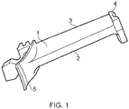
- the blade of Figure 1 has a concave surface 1 on an opposite face to a convex surface 2.
- the two surfaces 1, 2 meet at a trailing edge 3.
- the blade has a tip platform 4 and a root platform 5.
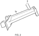
- Figure 2 shows the blade of Figure 1 in the process of having a surface of the trailing edge 3a machined by a tool 6.
- the machine tool 6 may be of a milling or grinding machine.
- Figure 3 shows the blade of Figure 1 arranged in a fixture according to an embodiment of the invention.
- the fixture comprises a pair of support bars 10a, 10b onto which the convex surface 2 of the blade is seated.
- Extending in an orthogonal plane is a pair of detachable end stops in the form of rods 11.
- the trailing edge 3 of the blade is aligned against the end stops 11.
- the convex surface 2 adjacent the trailing edge 3 is positioned flat against the supports 10a, 10b. This may be facilitated by means of a pivoted convex surface support 12.
- the tooling may further include a stop 13 in a third orthogonal direction against which the tip platform is aligned. In alternatives, the position of this stop could be on the opposite face of the tip platform 4, or on either face of the root platform 5.
- the stop 13 may be fixedly connected to a frame which also comprises the support bars 10a, 10b.
- the centrally pivoted clamp 14 is located approximately 1/3 of the way along the chordal length of the blade from the trailing edge 3 to the leading edge.
- This clamp 14 acts on the concave surface to force the part firmly against the supports 10a, 10b and the centrally pivoted counter-support 12, but without excessive force so as to cause distortion of the trailing edge.
- the blade is thus firmly gripped as a result of the reactionary forces from the clamp 14, the supports 10a, 10b and the centrally pivoted convex support 12.
- the trailing edge end stops 11 can now be retracted (e.g. vertically) away from the remainder of the tooling to allow access for the cutting tool 6 as shown in Figures 2 and 6 .
- the detail of the tooling design will depend on the specific geometry of the part to be machined, and in particular the relative distances and angles between the clamp 14 and the counter-support 12 and the trailing edge supports 10a and 10b, to ensure that the part is held firmly in position during the machining operation.
- the trailing edge 3 can be machined along the concave surface side of the trailing edge to form the desired thinner trailing edge profile.
- a measurement process such as a scanning probe or a laser system, may be used to measure the trailing edge thickness from the tip platform 4 to the root platform 5, or visa-versa, to make allowances for any part distortion, such as trailing edge bow, during the machining operation.
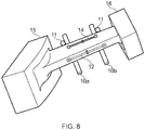
- the tip and root platforms 4, 5 of the blade are supported in compliant gripping fixtures 15, 16.
- the compliant gripping fixtures may be rotated and locked into position once the convex surface adjacent the trailing edge is in contact with the support bars 10a, 10b and the detachable end stops 11.
- the clamp 14 (which in this embodiment is positioned closer to the trailing edge 3) pushes the convex surface intimately against the supports 10a, 10b. With the blade properly positioned for subsequent machining, the compliant gripping fixtures 15, 16 are locked to maintain the position and the clamp 14 can be removed providing access to the concave side trailing edge for machining.
- the clamp 14 can be dispensed with once compliant gripping fixtures 15, 16 have been locked in position.
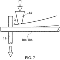
- the clamp 14 is arranged such that there is negligible force in a plane parallel to the support bars 10a, 10b.
- the position of the blade can be maintained whilst compliant gripping fixtures 15, 16 are locked in position.
- the centrally pivoted clamp 14 is positioned much closer to the apex of the trailing edge 3. This allows the trailing edge to be located more intimately against the supports 10a, 10b, thereby improving the accuracy of the setting and thus the final profile of the trailing edge. With this arrangement, the blade is clamped in position after it has been appropriately positioned and oriented.
- the compliant gripping fixtures 15, 16 can be arranged to hold a platform 4, 5 of the blade in a given orientation. Once the blade and compliant gripping fixtures 15, 16 are in the desired position and orientation, the ends of the fixtures 15, 16 are firmly clamped.
- the end stops 11 and clamp 14 are retracted away from the trailing edge 3 to allow access for the cutting tool 6 to machine the trailing edge 3.
- the material removal 17 is carried out relative to the datum system of the tool, in particular the supports 10a, 10b and the position of the trailing edge end stops 11 (prior to their removal).
Landscapes
- Engineering & Computer Science (AREA)
- Mechanical Engineering (AREA)
- General Engineering & Computer Science (AREA)
- Jigs For Machine Tools (AREA)
- Surgical Instruments (AREA)
Abstract
Description
- The present invention is concerned with accurate machining of surfaces of a complex shaped part. More particularly, the invention is concerned with a fixture for holding such a part securely in position whilst leaving the surface to be machined accessible. The invention has particular application (but is not strictly limited to) the machining of trailing edges of aerofoils, for example turbine blades.
- In the turbine stages of a gas turbine engine there are considerable efficiency losses associated with the aerodynamics of the trailing edges of the aerofoils. It is known that these losses can be greatly reduced if the trailing edge can be made consistently with a thinner profile, which improves the turbine efficiency and therefore decreases the specific fuel consumption.
- Turbine aerofoil components are conventionally manufactured by an investment casting process. This process inherently has limits on how thin sections can be cast due to surface tension effects. Typically, the smallest trailing edge thickness which can be reliably cast using the process is around 0.6 mm. To reliably manufacture trailing edge thicknesses of less than 0,6 mm it is desirable to carry out an operation such as machining of the cast component. To preserve the aerodynamic properties of the convex surface of the aerofoil it is further desirable that the material is removed from the concave surface during the thinning operation.
- It is known to use fully adaptive machining processes to thin the trailing edge of the cast aerofoil. One example of such an adaptive machining process is disclosed US patent application publication no.
US2014/373503A . Such processes are very effective, but very expensive adding significantly to unit cost of manufacture. - Fixtures for holding aerofoils during machining processes are known. For example, a 6 point location nest is described in US patent application publication no.
US2014/191455A . Whilst such arrangements can secure a part, they do not align a trailing edge for accurate machining with respect to the suction surface of the aerofoil. Also, these known arrangements do not provide unencumbered access to a machine tool along the entire length of the trailing edge. - Another example of a known fixture arrangement is described in the applicant's own US patent application publication
US2013318773A . Whilst the described arrangement allows good access to the trailing edge, the arrangement does not provide for accurate alignment of the trailing edge for machining by a conventional machine tool, an accurate result would require an adaptive machining solution. - The invention seeks to provide a fixture which sets a cast aerofoil in an orientation which is suitable for machining by a direct machining process such as milling.
- In accordance with the present invention there is provided fixture for locating a straight edge of a curved surface of a part and holding the part in a fixed position during performance of a machining operation on the concave side surface adjacent the straight edge, the tooling comprising;
- One or more supports for seating a convex curved surface of the part,
one or more detachable end stops arranged to extend in a plane orthogonal to that in which the support(s) sit and against which, in use, the straight edge can be aligned,
a clamp arranged, in use, to push the convex curved surface against the support(s) such that the straight edge contacts the support(s) without obstruction of the concave side surface adjacent the straight edge. - In use, a convex surface of the part is laid against the supports and tilted such that the straight edge lies against the support(s). The detachable end stops are positioned in the orthogonal plane and the straight edge is slid along the support until the straight edge is aligned with the end stops. With the straight edge in the desired position, the clamp is applied to hold the part in the desired position. The detachable end stops may then be removed exposing the concave side edge surface for machining.
- Desirably, the support includes two or more spaced ribs. For example, the ribs are in the form of two or more rods in parallel alignment. Alternatively, the support comprises a base onto which are integrally formed two or more protruding ribs. The ribs may have a rounded cross section. Alternatively the ribs may present an angled edge to the convex surface. Alternatively, the ribs may present a narrow flat surface to the convex surface.
- In another option, the support comprises a base with two or more spaced rows of protrusions, for example semi-spherical protrusions on to which the convex surface can be seated.
- The detachable end stop may comprise a flat plate. Alternatively, the end stop comprises two or more spaced apart rods. The rods may have a rounded cross section. Alternatively the rods may present an angled edge to the straight edge of the part. Alternatively, the rods may present a narrow flat surface to the straight edge.
- The fixture may further comprise a convex surface counter-support for countering any undesirable load from the clamp which may cause slippage and/or tilting of the part after it has been positioned. The counter support may, for example, comprise a wedge or a bar whose position is slidably adjustable to accommodate various degrees of curvature. The counter-support may comprise part of the clamp. The counter-support may comprise part of the support.
- The clamp and the counter support may comprise a pivoted clamp, for example centrally pivoted.
- The fixture may further comprise one or more additional stops arranged in a third plane orthogonal to both the plane in which the support(s) sits, to control the location of the blade in the direction of which the detachable end stops extend
- The skilled person will appreciate that except where mutually exclusive, a feature described in relation to any one of the above aspects may be applied mutatis mutandis to any other aspect. Furthermore except where mutually exclusive any feature described herein may be applied to any aspect and/or combined with any other feature described herein.
- Embodiments of the invention will now be further described with reference to the accompanying Figures in which;
-
Figure 1 shows a cast turbine blade having a curved surface and a straight trailing edge of the surface; -
Figure 2 illustrates how the turbine blade ofFigure 1 might be machined to provide a thinner trailing edge for a more aerodynamic performance; -
Figure 3 shows a view from a leading edge of the turbine blade ofFigure 1 arranged in tooling in accordance with a first embodiment of the invention; -
Figure 4 shows the arrangement ofFigure 3 with the blade clamped in the desired position and orientation; -
Figure 5 shows points at which the concave and convex surfaces of the blade ofFigure 4 are supported; -
Figure 6 shows material being removed from the trailing edge of a blade aligned and held using tooling in accordance with an embodiment of the invention. -
Figure 7 shows the loading applied to the blade by the clamp of the tooling ofFigure 8 ; -
Figure 8 illustrates a second embodiment of tooling in accordance with the invention applied to a blade which is the same as the blade ofFigure 1 ; -
Figure 9 illustrates a second embodiment of the tooling with the clamp shown inFigure 7 and8 removed - As can be seen the blade of
Figure 1 has aconcave surface 1 on an opposite face to aconvex surface 2. The twosurfaces trailing edge 3. The blade has atip platform 4 and aroot platform 5.Figure 2 shows the blade ofFigure 1 in the process of having a surface of thetrailing edge 3a machined by atool 6. For example, themachine tool 6 may be of a milling or grinding machine. -
Figure 3 shows the blade ofFigure 1 arranged in a fixture according to an embodiment of the invention. As can be seen, the fixture comprises a pair ofsupport bars convex surface 2 of the blade is seated. Extending in an orthogonal plane is a pair of detachable end stops in the form ofrods 11. The trailingedge 3 of the blade is aligned against the end stops 11. Desirably, theconvex surface 2 adjacent the trailingedge 3 is positioned flat against thesupports convex surface support 12. The tooling may further include astop 13 in a third orthogonal direction against which the tip platform is aligned. In alternatives, the position of this stop could be on the opposite face of thetip platform 4, or on either face of theroot platform 5. Thestop 13 may be fixedly connected to a frame which also comprises the support bars 10a, 10b. - As can be seen in
Figure 4 , once the trailingedge 3 is aligned with thedetachable rods 11, the blade is secured in position by a pivotedclamp 14. The pivotedconvex surface support 12 serves to counter any load from theclamp 14 which might push the trailing edge out of alignment with therods Figure 5 . - In the fixture shown in
Figures 4 and5 , the centrally pivotedclamp 14, is located approximately 1/3 of the way along the chordal length of the blade from the trailingedge 3 to the leading edge. Thisclamp 14 acts on the concave surface to force the part firmly against thesupports counter-support 12, but without excessive force so as to cause distortion of the trailing edge. The blade is thus firmly gripped as a result of the reactionary forces from theclamp 14, thesupports convex support 12. The trailing edge end stops 11 can now be retracted (e.g. vertically) away from the remainder of the tooling to allow access for thecutting tool 6 as shown inFigures 2 and6 . It is important to note that the detail of the tooling design will depend on the specific geometry of the part to be machined, and in particular the relative distances and angles between theclamp 14 and the counter-support 12 and the trailing edge supports 10a and 10b, to ensure that the part is held firmly in position during the machining operation. Following clamping of the part and retraction of the trailing edge stops 11, the trailingedge 3 can be machined along the concave surface side of the trailing edge to form the desired thinner trailing edge profile. To ensure an accurate trailing edge profile is generated, a measurement process, such as a scanning probe or a laser system, may be used to measure the trailing edge thickness from thetip platform 4 to theroot platform 5, or visa-versa, to make allowances for any part distortion, such as trailing edge bow, during the machining operation. - In an alternative embodiment as shown in
Figure 8 , the tip androot platforms gripping fixtures fixtures supports fixtures clamp 14 can be removed providing access to the concave side trailing edge for machining. - In this embodiment, the
clamp 14 can be dispensed with once compliantgripping fixtures Figure 7 , theclamp 14 is arranged such that there is negligible force in a plane parallel to the support bars 10a, 10b. Thus, the position of the blade can be maintained whilst compliant grippingfixtures - As can be seen in
Figure 9 , once the blade has been positioned and secured into position, thedetachable rods 11 are removed allowing amachine tool 6 to removematerial 17 from the trailing edge on the concave surface side. - In the tooling arrangement shown in
Figures 7 and8 the centrally pivotedclamp 14 is positioned much closer to the apex of the trailingedge 3. This allows the trailing edge to be located more intimately against thesupports counter support 12 of the previously described embodiment, the compliant grippingfixtures platform gripping fixtures fixtures edge 3 to allow access for thecutting tool 6 to machine the trailingedge 3. Thematerial removal 17 is carried out relative to the datum system of the tool, in particular thesupports
Claims (15)
- A fixture for locating a straight edge (3) of a curved surface (2) of a part and holding
the part in a fixed position during performance of a machining operation on a concave side surface adjacent the straight edge, the fixture comprising;
two or more elongate and spaced apart supports (10a, 10b) for seating a convex curved surface (2) of the part each elongate support (10a, 10b) extending straightly and in parallel with a chord of the convex curved surface (2),
one or more detachable end stops (11) arranged to extend in a plane orthogonal to that in which the elongate supports (10a, 10b) extend and against which, in use, the straight edge (3) can be aligned,
a clamp (14) arranged, in use, to push the convex curved surface (2) against the elongate supports (10a, 10b) such that the straight edge (3) contacts the support (10a, 10b) without obstruction of the concave side surface adjacent the straight edge (3). - A fixture as claimed in claim 1 wherein the supports (10a, 10b) comprise two or more spaced ribs.
- A fixture as claimed in claim 2 wherein the ribs are in the form of two or more rods (10a, 10b) in parallel alignment.
- A fixture as claimed in claim 2 or 3 wherein the supports comprises a base onto which are integrally formed the two or more protruding ribs.
- A fixture as claimed in claims 2 to 4 wherein the ribs (10a, 10b) have a rounded cross section.
- A fixture as claimed in any preceding claim wherein the detachable end stop (11) comprises two or more spaced apart rods.
- A fixture as claimed in claim 6 wherein the rods have a rounded cross section.
- A fixture as claimed in any preceding claim wherein the clamp (14) comprises a pivoted clamp.
- A fixture as claimed in claim 8 wherein the clamp (14) is centrally pivoted.
- A fixture as claimed in any preceding claim further comprising a convex surface counter-support (12) for countering any undesirable load from the clamp (14) which may cause slippage and/or tilting of the part after it has been positioned.
- A fixture as claimed in claim 10 wherein the counter support (12) comprises a wedge or a bar whose position is slidably adjustable to accommodate various degrees of curvature.
- A fixture as claimed in claim 10 wherein the counter-support (12) comprises a pivoted support.
- A fixture as claimed in any preceding claim further comprising one or more additional stops (13) arranged in a plane orthogonal to both the plane in which the support sits and the plane in which the detachable end stops (11) extend.
- A fixture as claimed in any of claims 1 to 9 further comprising a pair of compliant gripping fixtures (15, 16) configured to receive opposing ends of the part in a manner which does not permit the part to rotate relative to the compliant gripping fixtures (15,16).
- Use of a fixture according to any preceding claim to align and secure an aerofoil with its trailing edge (3) accessible to a machine tool and performing a machining operation with the machine tool to remove material from the trailing edge on a concave surface side of the aerofoil.
Applications Claiming Priority (1)
| Application Number | Priority Date | Filing Date | Title |
|---|---|---|---|
| GBGB1608639.9A GB201608639D0 (en) | 2016-05-17 | 2016-05-17 | Fixture for holding a complex-shaped part during a machining operation |
Publications (2)
| Publication Number | Publication Date |
|---|---|
| EP3246124A1 true EP3246124A1 (en) | 2017-11-22 |
| EP3246124B1 EP3246124B1 (en) | 2019-07-10 |
Family
ID=56320520
Family Applications (1)
| Application Number | Title | Priority Date | Filing Date |
|---|---|---|---|
| EP17169938.2A Active EP3246124B1 (en) | 2016-05-17 | 2017-05-08 | Fixture for holding a complex-shaped part during a machining operation |
Country Status (4)
| Country | Link |
|---|---|
| US (1) | US10589392B2 (en) |
| EP (1) | EP3246124B1 (en) |
| CN (2) | CN107378542B (en) |
| GB (1) | GB201608639D0 (en) |
Families Citing this family (2)
| Publication number | Priority date | Publication date | Assignee | Title |
|---|---|---|---|---|
| CN113664568B (en) * | 2021-09-29 | 2022-07-19 | 中国航发动力股份有限公司 | Measurement tool and coordinate system establishing method |
| US12109622B1 (en) | 2023-03-14 | 2024-10-08 | Rtx Corporation | Spindles peening offset fixture for CNC turning |
Citations (2)
| Publication number | Priority date | Publication date | Assignee | Title |
|---|---|---|---|---|
| FR2976203A1 (en) * | 2011-06-07 | 2012-12-14 | Snecma | Method for machining composite blade in aircraft industry, involves calculating difference between measured profile and predetermined theoretical profile, and machining faces of central portion of blade based on difference |
| FR2984788A1 (en) * | 2011-12-23 | 2013-06-28 | Snecma | Method for controlling turbine blade of turboshaft engine, involves performing control on blade by holding blade in support and positioning blade in plug parts in position identical to position of blade occupied during another control |
Family Cites Families (15)
| Publication number | Priority date | Publication date | Assignee | Title |
|---|---|---|---|---|
| US3827965A (en) * | 1973-02-02 | 1974-08-06 | United Aircraft Corp | Electrochemical drilling apparatus |
| GB9000580D0 (en) | 1990-01-10 | 1990-03-14 | Refurbished Turbine Components | Apparatus for and methods of the repair of turbine blades |
| US5168608A (en) * | 1990-01-10 | 1992-12-08 | Refurbished Turbine Components Limited | Apparatus for the repair of turbine blades |
| US5954464A (en) | 1997-09-05 | 1999-09-21 | United Technologies Corporation | Method for forming the edge of an airfoil |
| TW487617B (en) * | 2000-08-04 | 2002-05-21 | Smc Kk | Clamp apparatus |
| EP1935558A1 (en) * | 2006-12-19 | 2008-06-25 | Pilkington Italia S.p.A. | System and process for manufacturing frameless windows |
| CN101372046B (en) * | 2008-09-26 | 2011-02-02 | 无锡透平叶片有限公司 | Special fixture of drill blade top centre hole for blade |
| CN101804609B (en) * | 2010-03-23 | 2011-10-12 | 山东潍坊福田模具有限责任公司 | Special-shaped part machining quick clamping device |
| CN102145464B (en) * | 2010-11-20 | 2013-01-23 | 无锡透平叶片有限公司 | Locating and clamping device for machining bacterial type blade shroud |
| GB201102799D0 (en) | 2011-02-18 | 2011-04-06 | Rolls Royce Plc | Apparatus for immobilising a component during a machining operation |
| FR2976836B1 (en) | 2011-06-21 | 2013-06-21 | Snecma | DEVICE FOR MAINTAINING A TURBOMACHINE BLADE FOR MACHINING |
| GB2505496A (en) | 2012-09-03 | 2014-03-05 | Rolls Royce Plc | Fixture and method for securing an aerofoil |
| US9719356B2 (en) | 2013-06-21 | 2017-08-01 | Rolls-Royce Plc | Method of finishing a blade |
| CN203973245U (en) * | 2014-08-25 | 2014-12-03 | 哈尔滨汽轮机厂有限责任公司 | A kind of milling machine is pressed the blade locking device of guide vane milling pin for processing combustion |
| CN105415038B (en) * | 2015-12-31 | 2018-08-24 | 无锡透平叶片有限公司 | Fixture for steam turbine stator blade overall length wire cutting |
-
2016
- 2016-05-17 GB GBGB1608639.9A patent/GB201608639D0/en not_active Ceased
-
2017
- 2017-05-08 US US15/589,179 patent/US10589392B2/en not_active Expired - Fee Related
- 2017-05-08 EP EP17169938.2A patent/EP3246124B1/en active Active
- 2017-05-17 CN CN201710347942.0A patent/CN107378542B/en not_active Expired - Fee Related
- 2017-05-17 CN CN201720547603.2U patent/CN207014030U/en not_active Expired - Fee Related
Patent Citations (2)
| Publication number | Priority date | Publication date | Assignee | Title |
|---|---|---|---|---|
| FR2976203A1 (en) * | 2011-06-07 | 2012-12-14 | Snecma | Method for machining composite blade in aircraft industry, involves calculating difference between measured profile and predetermined theoretical profile, and machining faces of central portion of blade based on difference |
| FR2984788A1 (en) * | 2011-12-23 | 2013-06-28 | Snecma | Method for controlling turbine blade of turboshaft engine, involves performing control on blade by holding blade in support and positioning blade in plug parts in position identical to position of blade occupied during another control |
Also Published As
| Publication number | Publication date |
|---|---|
| US10589392B2 (en) | 2020-03-17 |
| CN107378542B (en) | 2021-03-16 |
| CN107378542A (en) | 2017-11-24 |
| US20170334029A1 (en) | 2017-11-23 |
| CN207014030U (en) | 2018-02-16 |
| EP3246124B1 (en) | 2019-07-10 |
| GB201608639D0 (en) | 2016-06-29 |
Similar Documents
| Publication | Publication Date | Title |
|---|---|---|
| US3818646A (en) | Fixture for holding precisely shaped parts | |
| US20130323071A1 (en) | Polishing assembly and method for polishing | |
| US20030114082A1 (en) | Fixture for clamping a gas turbine component and its use in shaping the gas turbine component | |
| RU2582405C2 (en) | Support for fixation of blade by means of blades thereof during mechanical processing of said blade shank | |
| US10589392B2 (en) | Fixture for holding a complex-shaped part during a machining operation | |
| US20130318773A1 (en) | Apparatus for immobilising a component during a machining operation | |
| EP1806477A2 (en) | Turbine element repair fixture | |
| CN205096893U (en) | Swallow tail head lobe piece mills processes anchor clamps for blade profile | |
| JP4236917B2 (en) | Fixing jig for clamping gas turbine parts and its use in shape processing of gas turbine parts | |
| US10556310B2 (en) | Method for cutting machining of turbine blades | |
| US20030114080A1 (en) | Fixture for clamping a gas turbine component blank and its use in shaping the gas turbine component blank | |
| US3920947A (en) | Turbine-nozzle manufacturing apparatus and method | |
| EP2471631A2 (en) | A system for forming a labyrinth seal | |
| EP4183977A1 (en) | Airfoil joining apparatus and methods | |
| CN111551391A (en) | Aeroengine turbine blade sampling clamp | |
| JP2003508234A (en) | Machine tools with fastening devices | |
| GB2533971A (en) | Method and apparatus for machining a blade | |
| US20220316802A1 (en) | Vacuum Forming Method | |
| GB2625455A (en) | Device and method for milling of complex grid-type ribbed member by precise machining allowance | |
| CN223147334U (en) | Pitch handle processingequipment | |
| CN120734401B (en) | Pre-processing method and fixture for longitudinal tree-type leaf root type leaves | |
| JP2020131331A (en) | Blade gripping jig | |
| CN205927891U (en) | Take coronule to crumple stator and mill assembly groove anchor clamps on inclined plane of both ends | |
| US11454123B2 (en) | Method for machining free-form surface on elongated material |
Legal Events
| Date | Code | Title | Description |
|---|---|---|---|
| PUAI | Public reference made under article 153(3) epc to a published international application that has entered the european phase |
Free format text: ORIGINAL CODE: 0009012 |
|
| STAA | Information on the status of an ep patent application or granted ep patent |
Free format text: STATUS: THE APPLICATION HAS BEEN PUBLISHED |
|
| AK | Designated contracting states |
Kind code of ref document: A1 Designated state(s): AL AT BE BG CH CY CZ DE DK EE ES FI FR GB GR HR HU IE IS IT LI LT LU LV MC MK MT NL NO PL PT RO RS SE SI SK SM TR |
|
| AX | Request for extension of the european patent |
Extension state: BA ME |
|
| STAA | Information on the status of an ep patent application or granted ep patent |
Free format text: STATUS: REQUEST FOR EXAMINATION WAS MADE |
|
| 17P | Request for examination filed |
Effective date: 20180522 |
|
| RBV | Designated contracting states (corrected) |
Designated state(s): AL AT BE BG CH CY CZ DE DK EE ES FI FR GB GR HR HU IE IS IT LI LT LU LV MC MK MT NL NO PL PT RO RS SE SI SK SM TR |
|
| GRAP | Despatch of communication of intention to grant a patent |
Free format text: ORIGINAL CODE: EPIDOSNIGR1 |
|
| STAA | Information on the status of an ep patent application or granted ep patent |
Free format text: STATUS: GRANT OF PATENT IS INTENDED |
|
| GRAJ | Information related to disapproval of communication of intention to grant by the applicant or resumption of examination proceedings by the epo deleted |
Free format text: ORIGINAL CODE: EPIDOSDIGR1 |
|
| STAA | Information on the status of an ep patent application or granted ep patent |
Free format text: STATUS: REQUEST FOR EXAMINATION WAS MADE |
|
| GRAP | Despatch of communication of intention to grant a patent |
Free format text: ORIGINAL CODE: EPIDOSNIGR1 |
|
| STAA | Information on the status of an ep patent application or granted ep patent |
Free format text: STATUS: GRANT OF PATENT IS INTENDED |
|
| INTG | Intention to grant announced |
Effective date: 20190318 |
|
| INTC | Intention to grant announced (deleted) | ||
| GRAS | Grant fee paid |
Free format text: ORIGINAL CODE: EPIDOSNIGR3 |
|
| INTG | Intention to grant announced |
Effective date: 20190415 |
|
| GRAA | (expected) grant |
Free format text: ORIGINAL CODE: 0009210 |
|
| STAA | Information on the status of an ep patent application or granted ep patent |
Free format text: STATUS: THE PATENT HAS BEEN GRANTED |
|
| AK | Designated contracting states |
Kind code of ref document: B1 Designated state(s): AL AT BE BG CH CY CZ DE DK EE ES FI FR GB GR HR HU IE IS IT LI LT LU LV MC MK MT NL NO PL PT RO RS SE SI SK SM TR |
|
| REG | Reference to a national code |
Ref country code: GB Ref legal event code: FG4D |
|
| REG | Reference to a national code |
Ref country code: CH Ref legal event code: EP Ref country code: AT Ref legal event code: REF Ref document number: 1153013 Country of ref document: AT Kind code of ref document: T Effective date: 20190715 |
|
| REG | Reference to a national code |
Ref country code: DE Ref legal event code: R096 Ref document number: 602017005118 Country of ref document: DE |
|
| REG | Reference to a national code |
Ref country code: IE Ref legal event code: FG4D |
|
| REG | Reference to a national code |
Ref country code: NL Ref legal event code: MP Effective date: 20190710 |
|
| REG | Reference to a national code |
Ref country code: LT Ref legal event code: MG4D |
|
| REG | Reference to a national code |
Ref country code: AT Ref legal event code: MK05 Ref document number: 1153013 Country of ref document: AT Kind code of ref document: T Effective date: 20190710 |
|
| PG25 | Lapsed in a contracting state [announced via postgrant information from national office to epo] |
Ref country code: NO Free format text: LAPSE BECAUSE OF FAILURE TO SUBMIT A TRANSLATION OF THE DESCRIPTION OR TO PAY THE FEE WITHIN THE PRESCRIBED TIME-LIMIT Effective date: 20191010 Ref country code: BG Free format text: LAPSE BECAUSE OF FAILURE TO SUBMIT A TRANSLATION OF THE DESCRIPTION OR TO PAY THE FEE WITHIN THE PRESCRIBED TIME-LIMIT Effective date: 20191010 Ref country code: SE Free format text: LAPSE BECAUSE OF FAILURE TO SUBMIT A TRANSLATION OF THE DESCRIPTION OR TO PAY THE FEE WITHIN THE PRESCRIBED TIME-LIMIT Effective date: 20190710 Ref country code: AT Free format text: LAPSE BECAUSE OF FAILURE TO SUBMIT A TRANSLATION OF THE DESCRIPTION OR TO PAY THE FEE WITHIN THE PRESCRIBED TIME-LIMIT Effective date: 20190710 Ref country code: HR Free format text: LAPSE BECAUSE OF FAILURE TO SUBMIT A TRANSLATION OF THE DESCRIPTION OR TO PAY THE FEE WITHIN THE PRESCRIBED TIME-LIMIT Effective date: 20190710 Ref country code: LT Free format text: LAPSE BECAUSE OF FAILURE TO SUBMIT A TRANSLATION OF THE DESCRIPTION OR TO PAY THE FEE WITHIN THE PRESCRIBED TIME-LIMIT Effective date: 20190710 Ref country code: PT Free format text: LAPSE BECAUSE OF FAILURE TO SUBMIT A TRANSLATION OF THE DESCRIPTION OR TO PAY THE FEE WITHIN THE PRESCRIBED TIME-LIMIT Effective date: 20191111 Ref country code: NL Free format text: LAPSE BECAUSE OF FAILURE TO SUBMIT A TRANSLATION OF THE DESCRIPTION OR TO PAY THE FEE WITHIN THE PRESCRIBED TIME-LIMIT Effective date: 20190710 Ref country code: FI Free format text: LAPSE BECAUSE OF FAILURE TO SUBMIT A TRANSLATION OF THE DESCRIPTION OR TO PAY THE FEE WITHIN THE PRESCRIBED TIME-LIMIT Effective date: 20190710 |
|
| RAP2 | Party data changed (patent owner data changed or rights of a patent transferred) |
Owner name: ROLLS-ROYCE PLC |
|
| PG25 | Lapsed in a contracting state [announced via postgrant information from national office to epo] |
Ref country code: ES Free format text: LAPSE BECAUSE OF FAILURE TO SUBMIT A TRANSLATION OF THE DESCRIPTION OR TO PAY THE FEE WITHIN THE PRESCRIBED TIME-LIMIT Effective date: 20190710 Ref country code: GR Free format text: LAPSE BECAUSE OF FAILURE TO SUBMIT A TRANSLATION OF THE DESCRIPTION OR TO PAY THE FEE WITHIN THE PRESCRIBED TIME-LIMIT Effective date: 20191011 Ref country code: RS Free format text: LAPSE BECAUSE OF FAILURE TO SUBMIT A TRANSLATION OF THE DESCRIPTION OR TO PAY THE FEE WITHIN THE PRESCRIBED TIME-LIMIT Effective date: 20190710 Ref country code: IS Free format text: LAPSE BECAUSE OF FAILURE TO SUBMIT A TRANSLATION OF THE DESCRIPTION OR TO PAY THE FEE WITHIN THE PRESCRIBED TIME-LIMIT Effective date: 20191110 Ref country code: AL Free format text: LAPSE BECAUSE OF FAILURE TO SUBMIT A TRANSLATION OF THE DESCRIPTION OR TO PAY THE FEE WITHIN THE PRESCRIBED TIME-LIMIT Effective date: 20190710 Ref country code: LV Free format text: LAPSE BECAUSE OF FAILURE TO SUBMIT A TRANSLATION OF THE DESCRIPTION OR TO PAY THE FEE WITHIN THE PRESCRIBED TIME-LIMIT Effective date: 20190710 |
|
| PG25 | Lapsed in a contracting state [announced via postgrant information from national office to epo] |
Ref country code: TR Free format text: LAPSE BECAUSE OF FAILURE TO SUBMIT A TRANSLATION OF THE DESCRIPTION OR TO PAY THE FEE WITHIN THE PRESCRIBED TIME-LIMIT Effective date: 20190710 |
|
| PG25 | Lapsed in a contracting state [announced via postgrant information from national office to epo] |
Ref country code: IT Free format text: LAPSE BECAUSE OF FAILURE TO SUBMIT A TRANSLATION OF THE DESCRIPTION OR TO PAY THE FEE WITHIN THE PRESCRIBED TIME-LIMIT Effective date: 20190710 Ref country code: RO Free format text: LAPSE BECAUSE OF FAILURE TO SUBMIT A TRANSLATION OF THE DESCRIPTION OR TO PAY THE FEE WITHIN THE PRESCRIBED TIME-LIMIT Effective date: 20190710 Ref country code: DK Free format text: LAPSE BECAUSE OF FAILURE TO SUBMIT A TRANSLATION OF THE DESCRIPTION OR TO PAY THE FEE WITHIN THE PRESCRIBED TIME-LIMIT Effective date: 20190710 Ref country code: EE Free format text: LAPSE BECAUSE OF FAILURE TO SUBMIT A TRANSLATION OF THE DESCRIPTION OR TO PAY THE FEE WITHIN THE PRESCRIBED TIME-LIMIT Effective date: 20190710 Ref country code: PL Free format text: LAPSE BECAUSE OF FAILURE TO SUBMIT A TRANSLATION OF THE DESCRIPTION OR TO PAY THE FEE WITHIN THE PRESCRIBED TIME-LIMIT Effective date: 20190710 |
|
| PG25 | Lapsed in a contracting state [announced via postgrant information from national office to epo] |
Ref country code: IS Free format text: LAPSE BECAUSE OF FAILURE TO SUBMIT A TRANSLATION OF THE DESCRIPTION OR TO PAY THE FEE WITHIN THE PRESCRIBED TIME-LIMIT Effective date: 20200224 Ref country code: SK Free format text: LAPSE BECAUSE OF FAILURE TO SUBMIT A TRANSLATION OF THE DESCRIPTION OR TO PAY THE FEE WITHIN THE PRESCRIBED TIME-LIMIT Effective date: 20190710 Ref country code: SM Free format text: LAPSE BECAUSE OF FAILURE TO SUBMIT A TRANSLATION OF THE DESCRIPTION OR TO PAY THE FEE WITHIN THE PRESCRIBED TIME-LIMIT Effective date: 20190710 Ref country code: CZ Free format text: LAPSE BECAUSE OF FAILURE TO SUBMIT A TRANSLATION OF THE DESCRIPTION OR TO PAY THE FEE WITHIN THE PRESCRIBED TIME-LIMIT Effective date: 20190710 |
|
| REG | Reference to a national code |
Ref country code: DE Ref legal event code: R097 Ref document number: 602017005118 Country of ref document: DE |
|
| PLBE | No opposition filed within time limit |
Free format text: ORIGINAL CODE: 0009261 |
|
| STAA | Information on the status of an ep patent application or granted ep patent |
Free format text: STATUS: NO OPPOSITION FILED WITHIN TIME LIMIT |
|
| PG2D | Information on lapse in contracting state deleted |
Ref country code: IS |
|
| 26N | No opposition filed |
Effective date: 20200603 |
|
| PG25 | Lapsed in a contracting state [announced via postgrant information from national office to epo] |
Ref country code: SI Free format text: LAPSE BECAUSE OF FAILURE TO SUBMIT A TRANSLATION OF THE DESCRIPTION OR TO PAY THE FEE WITHIN THE PRESCRIBED TIME-LIMIT Effective date: 20190710 |
|
| REG | Reference to a national code |
Ref country code: DE Ref legal event code: R119 Ref document number: 602017005118 Country of ref document: DE |
|
| PG25 | Lapsed in a contracting state [announced via postgrant information from national office to epo] |
Ref country code: CH Free format text: LAPSE BECAUSE OF NON-PAYMENT OF DUE FEES Effective date: 20200531 Ref country code: LI Free format text: LAPSE BECAUSE OF NON-PAYMENT OF DUE FEES Effective date: 20200531 Ref country code: MC Free format text: LAPSE BECAUSE OF FAILURE TO SUBMIT A TRANSLATION OF THE DESCRIPTION OR TO PAY THE FEE WITHIN THE PRESCRIBED TIME-LIMIT Effective date: 20190710 |
|
| REG | Reference to a national code |
Ref country code: BE Ref legal event code: MM Effective date: 20200531 |
|
| PG25 | Lapsed in a contracting state [announced via postgrant information from national office to epo] |
Ref country code: LU Free format text: LAPSE BECAUSE OF NON-PAYMENT OF DUE FEES Effective date: 20200508 |
|
| PG25 | Lapsed in a contracting state [announced via postgrant information from national office to epo] |
Ref country code: IE Free format text: LAPSE BECAUSE OF NON-PAYMENT OF DUE FEES Effective date: 20200508 Ref country code: FR Free format text: LAPSE BECAUSE OF NON-PAYMENT OF DUE FEES Effective date: 20200531 |
|
| PG25 | Lapsed in a contracting state [announced via postgrant information from national office to epo] |
Ref country code: BE Free format text: LAPSE BECAUSE OF NON-PAYMENT OF DUE FEES Effective date: 20200531 Ref country code: DE Free format text: LAPSE BECAUSE OF NON-PAYMENT OF DUE FEES Effective date: 20201201 |
|
| GBPC | Gb: european patent ceased through non-payment of renewal fee |
Effective date: 20210508 |
|
| PG25 | Lapsed in a contracting state [announced via postgrant information from national office to epo] |
Ref country code: GB Free format text: LAPSE BECAUSE OF NON-PAYMENT OF DUE FEES Effective date: 20210508 |
|
| PG25 | Lapsed in a contracting state [announced via postgrant information from national office to epo] |
Ref country code: MT Free format text: LAPSE BECAUSE OF FAILURE TO SUBMIT A TRANSLATION OF THE DESCRIPTION OR TO PAY THE FEE WITHIN THE PRESCRIBED TIME-LIMIT Effective date: 20190710 Ref country code: CY Free format text: LAPSE BECAUSE OF FAILURE TO SUBMIT A TRANSLATION OF THE DESCRIPTION OR TO PAY THE FEE WITHIN THE PRESCRIBED TIME-LIMIT Effective date: 20190710 |
|
| PG25 | Lapsed in a contracting state [announced via postgrant information from national office to epo] |
Ref country code: MK Free format text: LAPSE BECAUSE OF FAILURE TO SUBMIT A TRANSLATION OF THE DESCRIPTION OR TO PAY THE FEE WITHIN THE PRESCRIBED TIME-LIMIT Effective date: 20190710 |