EP3246114A1 - Low-pressure casting method and low-pressure casting apparatus - Google Patents
Low-pressure casting method and low-pressure casting apparatus Download PDFInfo
- Publication number
- EP3246114A1 EP3246114A1 EP15877831.6A EP15877831A EP3246114A1 EP 3246114 A1 EP3246114 A1 EP 3246114A1 EP 15877831 A EP15877831 A EP 15877831A EP 3246114 A1 EP3246114 A1 EP 3246114A1
- Authority
- EP
- European Patent Office
- Prior art keywords
- mold
- core
- cavity
- molten metal
- low
- Prior art date
- Legal status (The legal status is an assumption and is not a legal conclusion. Google has not performed a legal analysis and makes no representation as to the accuracy of the status listed.)
- Granted
Links
Images




Classifications
-
- B—PERFORMING OPERATIONS; TRANSPORTING
- B22—CASTING; POWDER METALLURGY
- B22D—CASTING OF METALS; CASTING OF OTHER SUBSTANCES BY THE SAME PROCESSES OR DEVICES
- B22D18/00—Pressure casting; Vacuum casting
- B22D18/04—Low pressure casting, i.e. making use of pressures up to a few bars to fill the mould
-
- B—PERFORMING OPERATIONS; TRANSPORTING
- B22—CASTING; POWDER METALLURGY
- B22C—FOUNDRY MOULDING
- B22C1/00—Compositions of refractory mould or core materials; Grain structures thereof; Chemical or physical features in the formation or manufacture of moulds
- B22C1/16—Compositions of refractory mould or core materials; Grain structures thereof; Chemical or physical features in the formation or manufacture of moulds characterised by the use of binding agents; Mixtures of binding agents
- B22C1/18—Compositions of refractory mould or core materials; Grain structures thereof; Chemical or physical features in the formation or manufacture of moulds characterised by the use of binding agents; Mixtures of binding agents of inorganic agents
-
- B—PERFORMING OPERATIONS; TRANSPORTING
- B22—CASTING; POWDER METALLURGY
- B22C—FOUNDRY MOULDING
- B22C9/00—Moulds or cores; Moulding processes
- B22C9/06—Permanent moulds for shaped castings
-
- B—PERFORMING OPERATIONS; TRANSPORTING
- B22—CASTING; POWDER METALLURGY
- B22C—FOUNDRY MOULDING
- B22C9/00—Moulds or cores; Moulding processes
- B22C9/18—Finishing
-
- B—PERFORMING OPERATIONS; TRANSPORTING
- B22—CASTING; POWDER METALLURGY
- B22D—CASTING OF METALS; CASTING OF OTHER SUBSTANCES BY THE SAME PROCESSES OR DEVICES
- B22D18/00—Pressure casting; Vacuum casting
- B22D18/08—Controlling, supervising, e.g. for safety reasons
-
- B—PERFORMING OPERATIONS; TRANSPORTING
- B22—CASTING; POWDER METALLURGY
- B22D—CASTING OF METALS; CASTING OF OTHER SUBSTANCES BY THE SAME PROCESSES OR DEVICES
- B22D27/00—Treating the metal in the mould while it is molten or ductile ; Pressure or vacuum casting
- B22D27/15—Treating the metal in the mould while it is molten or ductile ; Pressure or vacuum casting by using vacuum
-
- B—PERFORMING OPERATIONS; TRANSPORTING
- B22—CASTING; POWDER METALLURGY
- B22C—FOUNDRY MOULDING
- B22C9/00—Moulds or cores; Moulding processes
- B22C9/12—Treating moulds or cores, e.g. drying, hardening
-
- B—PERFORMING OPERATIONS; TRANSPORTING
- B22—CASTING; POWDER METALLURGY
- B22D—CASTING OF METALS; CASTING OF OTHER SUBSTANCES BY THE SAME PROCESSES OR DEVICES
- B22D18/00—Pressure casting; Vacuum casting
- B22D18/06—Vacuum casting, i.e. making use of vacuum to fill the mould
Definitions
- the present invention relates to a low-pressure casting method and a low-pressure casting apparatus.
- the present invention relates to a low-pressure casting method and a low-pressure casting apparatus that can prevent gas defects.
- Molten metal that is discharged from a melting furnace has high cleanliness since inclusions such as hydrogen gas, oxides and intermetallic compounds are removed by a flux treatment and degassing.
- the cleanliness of the molten metal is gradually decreased, since contact between molten metal and air is inevitable.
- a core which is disposed inside a mold, contains water, resin and the like.
- Such water, resin and the like are vaporized by the heat of molten metal to produce gas.
- water also produces hydrogen gas that causes hydrogen embrittlement of a molded product, it is important to remove water and the like that are vaporized by heat of molten metal in order to improve the quality of the molded product.
- Patent Document 1 discloses installing a pipe for suctioning gas inside the bodies of a mold and a core made of casting sand, and vacuuming the bodies of the mold or the core to partly reduce the pressure while supplying molten metal to a cavity, so as to suction gas that is generated from the bodies of the mold and the core. It discloses that this method can prevent gas that is produced by thermal decomposition of an organic binder contained in the mold and the like, from penetrating into molten steel, and thereby can prevent gas defects.
- Patent Document 2 discloses using an adsorbent such as zeolite or ALC instead of a technique of feeding hot air to a cavity to dry a sand mold that defines the cavity, since such techniques can remove only water that is present in the surface layer of the sand mold. That is, it discloses surrounding the casting sand of the mold by the adsorbent such as zeolite or ALC and allowing the adsorbent to adsorb and remove water of the casting sand even to the inner part. Further, it also describes forming a core, if employed, from a sand mold of casting sand, an adsorbent embedded inside the sand mold and a reinforcing steel embedded inside the adsorbent.
- an adsorbent such as zeolite or ALC
- the molten metal may be suctioned into gaps between the casting sand to cause a sand mark, or insufficient pressure reduction may cause a gas defect. That is, it is difficult to uniformly reduce the pressure in the bodies of the mold and the core, and the inner pressure of the mold and the like tend to vary. Further, gas from the mold and the like is not only derived from the organic binder but also produced from water contained in the mold and the like. Since the water content changes depending on the storage environment of the mold and the like, it is also difficult to estimate the amount of gas to be produced by pouring molten metal beforehand.
- the adsorbent has a certain capacity with regard to the amount of adsorption, and it is necessary to store the mold and core so that the mold and core do not absorb water over the capacity of adsorption of the mold and core. Furthermore, it requires considerable manpower to produce the mold and core, which increases the cost.
- the present invention has been made in view of these problems with the prior art. It is an object of the invention to provide a low-pressure casting method and a low-pressure casting apparatus that do not require any special processing, such as piping, other than shaping of a mold and a core, while it can reduce gas produced by heat of molten metal so as to prevent gas defects and shrinkage cavities, and it facilitates storage of the core.
- the present inventors have found that the above-described object can be achieved in a low-pressure casting method by reducing the pressure in a cavity to dry a core after disposing the core in a mold and closing the mold and before filling the mold with molten metal.
- the present invention has been thus completed.
- the present invention is based on the above-described finding, and the low-pressure casting method of the present invention is characterized by disposing a core in a mold, closing the mold, drying the core in the mold under reduced pressure, and thereafter filling the cavity with molten metal.
- the low-pressure casting apparatus of the present invention includes a core that together with a mold forms a cavity and a decompressor configured to dry the core under reduced pressure, wherein the core is disposed in the mold, the mold is closed, the core is dried under reduced pressure, and thereafter the cavity is filled with molten metal.
- the core is dried by reducing the pressure in the mold, before the cavity is filled with molten metal, and thereby removing water therein. This reduces production of gas such as water vapor due to heat of the molten metal and thereby prevents gas defects and shrinkage cavities. Furthermore, it is possible to provide the low-pressure casting method and the low-pressure casting apparatus that prevent gas production to achieve the stable running behavior of the molten metal so as to produce high-quality molded products and that facilitate storage of the core and the like.
- the present invention involves disposing a core in a mold, reducing the pressure in a cavity to remove water and the like contained in the core to dry it, thereafter filling the cavity with molten metal to cast a molded product, and opening the mold to collect the molded product.
- the drying of the core starts from the surface. Then, when the water content of the surface is decreased, water transfers from the inner part where the water content is high to the surface and is evaporated from the surface. The evaporation and transfer are repeated so that the core is dried thoroughly to the inner part. Accordingly, the higher the water transfer rate from a high-water content part to a low-water content part, the more rapidly the core is dried. That is, the larger the difference in water vapor partial pressure or the higher the temperature of the core, the higher the drying speed of the core.
- a molded product is produced by communicating a holding furnace storing molten metal with a cavity in a mold disposed above the holding furnace through a stalk, increasing the pressure in the holding furnace to fill the cavity with the molten metal through the stalk, and allowing the molten metal to solidify.
- FIG. 1 is a cross sectional view of an example of the low-pressure casting apparatus of the present invention.
- a low-pressure casting apparatus 1 is configured such that the lower end of a stalk 4 is dipped in molten metal 3 in a hermetically closed holding furnace 2, and a gate 5 is provided at the upper end of the stalk 4.
- a mold 6 is disposed which is splittable into upper and lower parts.
- a core 8 is accommodated and is positioned by a core print 7.
- the mold 6 and the core 8 form a cavity 9.
- the entire mold 6 may be covered with a chamber 10.
- the chamber 10 can reduce heat dissipation and thereby improve the heat efficiency.
- the holding furnace 2 is provided with a compressor 11 which pumps or discharges inert gas such as carbon dioxide into or from the holding furnace to adjust the pressure in the holding furnace so as to fill the cavity with the molten metal 3 through the stalk 4.
- the compressor 11 includes a compression pump 12, a valve 13, a pressure sensor (not shown) and the like.
- a decompressor 14 which dries the core under reduced pressure, is composed of a decompression pump 15, a decompression container 16, a valve 17, a suction pipe 18 and the like, in which the suction opening 19 of the suction pipe 18 is disposed in the chamber 10 and/or the mold 6. It is preferred suction openings 19 are provided at different locations.
- the core in the mold may be dried under reduced pressure as illustrated in FIG. 1 by reducing the pressure in the chamber 10 covering the entire mold 6 so as to reduce the pressure in the mold through the gap between the splittable mold 6.
- the core may be dried as illustrated in FIG. 2 by directly reducing the pressure in the cavity 9.
- the core 8 may be dried under reduced pressure as illustrated in FIG. 3 by vacuuming the core 8 through a porous body 21 that is disposed at the location of the core print 7 for fixing the core 8 in the mold.
- the core may be dried by their combination.
- the mold 6 is closed and the cavity 9 is vacuumed. This allows the mold to serve as a drying chamber for the core 8, and the core 8 can therefore be dried efficiently.
- the pressure in the chamber 10 may also be reduced as illustrated in FIG. 2 and FIG. 3 in addition to directly reducing the pressure in the cavity 9. This reduces the pressure difference between the chamber 10 and the cavity 9 and can thus prevent a leakage of the air in the chamber 10 to the cavity 9 even when the mold 6 splittable into the upper and lower parts does not achieve a completely hermetic condition.
- the core may be dried under reduced pressure by means of suction through the core print.
- the suction through the core print allows directly suctioning the water from the inner part of the core to dry it. Further, this also facilitates the heat transfer from the molten metal to the inner part of the core and can thereby improve the drying speed of the core 8.
- a gas purging path connected to the porous body may be provided inside the core 8 and the core print 7. The suction through this route allows water to be evaporated not only from the vicinity of the core print 7 but also from the entire inner part of the core. This can further improve the drying speed of the core 8.
- vacuuming the cavity 9 also while filling it with the molten metal 3 it is possible to suction gas that is produced by thermal decomposition of an organic binder or the like of the core 8. This can not only prevent gas defects but also achieve the stable running behavior. Therefore, it is possible to obtain a high-quality molded product.
- the pressure in the cavity 9 is preferably from the atmospheric pressure to 0.75 atmospheres, more preferably from 0.9 atmospheres to 0.75 atmospheres, although it depends on the size of the core 8, the temperature of the molten metal 3, the air-tightness of the mold and the like.
- the pressure being less than 0.75 atmospheres may have a negative influence such as the decreased temperature of the preceding molten metal at the start of the casting, since the molten metal rises excessively in the stalk.
- the low-pressure casting method using the above-described low-pressure casting apparatus 1 will be described.
- the mold 6 is opened, the core 8 is disposed in the mold along with the core print 7 for positioning the core in the mold, and the mold 6 is closed.
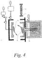
- a releasing powder 22 may be applied to the inner wall of the mold 6 as illustrated in FIG. 4 before the disposal of the core 8.
- the releasing powder 22 can be applied by an applying method known in the art such as spraying.
- the cavity 9 Before the mold 6 is closed, the cavity 9 may be partly opened in a half-closed condition so that gas can flow into the cavity 9, and cavity 9 may be vacuumed in this condition by means of the decompressor 14 that is directly connected to the cavity 9.
- Such preliminary vacuuming of the cavity 9 in the half-closed condition enables removing the releasing powder 21 that is not adhered to the casting surface, foreign substances that was incorporated when the core was disposed, and the like.
- the decompressor 14 that is directly connected to the cavity 9 includes a powder separator 20 such as a cyclone separator. With the powder separator 20, it is possible to trap dust in the mold so as to prevent malfunction of a decompression pump.
- hot air 23 that has been heated by the heat of the molten metal 3 rises to increase the temperature in the cavity as illustrated in FIG. 5 .
- the core 8 is heated by the hot air 23 in the cavity and starts to be dried.
- a core using an inorganic binder may also be used as well as ones using an organic binder including resin.
- a core using an inorganic binder produces less gas in the casting but has low strength due to low adhesion.
- the core since the core can be sufficiently dried, the strength of the core using an inorganic binder is improved, and the occurrence of defects caused by core breakage is decreased.
- inorganic binders examples include magnesium sulfate (MgSO 4 ), sodium carbonate (Na 2 CO 3 ), sodium tetraborate (Na 2 B 4 O 7 ), sodium sulfate (Na 2 SO 4 ) and the like.
- inert gas is pumped into the holding furnace 2 by means of the compressor 10 to apply a pressure on the surface of the molten metal so that the cavity 9 is filled with the molten metal 3 through the stalk 4. Then, when the molten metal 3 is solidified, the mold 6 is opened, and a molded product is collected.
- water in the core 8 is removed beforehand, a reduced amount of gas is produced by the heat of the molten metal 3. This stabilizes the running behavior of the molten metal and thus prevents gas defects and shrinkage cavities.
- the cavity 9 is vacuumed while the cavity 9 is being filled with the molten metal 3.
- the binder of the core 8 may sometimes be evaporated to produce gas due to the heat of the molten metal 3. Therefore, by vacuuming the cavity 9 while filling the cavity 9 with the molten metal 3, the running behavior of the molten metal is stabilized, which prevents gas defects and shrinkage cavities.
- FIG. 8 (a) , "A” represents the step of drying the core 8 by hermetically closing the mold 6 and reducing the pressure in the cavity.
- “B” represents the step of raising the molten metal 3 in the stalk 4 by the first compression of the holding furnace 2.
- “C” represents the step of switching the compression to the second compression that provides the controlled filling rate and restarting the vacuuming of the mold 6 when the molten metal 3 has reached the gate 5.
- the vacuuming of the cavity is continued for a certain time even after the mold 6 is filled with the molten metal 3.
- the preceding molten metal containing impurities is discharged from the mold 6 so that the quality of the molded product is improved.
- "D" represents the step of allowing the molten metal in the mold 6 to solidify. Once the molten metal 3 is solidified, the pressure in the holding furnace 2 is gradually increased, the mold 6 is opened, and the casted product is collected.
- FIG. 8 (b) illustrates an example in which the reduced pressure in the cavity is maintained even while the molten metal 3 in the stalk 4 is raised by means of the first compression of the holding furnace 2.
- FIG. 9 (a) illustrates the timing of the compression of the holding furnace 2, the decompression of the cavity and the decompression of the core 8 in the case of FIG. 3 in an example in which the suction pipe 11 is connected to the core print 7 for fixing the core 8.
- the compression of the holding furnace 2 and the decompression of the cavity are the same as those in FIG. 8 , and the timing of vacuuming the core 8 will be described.
- "A” is the step of closing the mold 6 and drying the core 8 by means of suction. As illustrated in FIG.
- the drying of the core 8 may be continued while the molten metal is raised in the stalk 4 by means of the first compression of the holding furnace 2 in Step B, but is stopped when the molten metal 3 reaches the gate 5 and starts to flow into the cavity.
- the vacuuming of core 8 is continued even after the molten metal 3 flows in, the molten metal 3 may get into the core 8 to cause a sand mark.
- the molten metal holding furnace may be composed of two chambers of a molten metal holding chamber and a compression chamber. Further, an electromagnetic pump may be employed instead of a compression pump for supplying the molten metal 3.
Landscapes
- Engineering & Computer Science (AREA)
- Mechanical Engineering (AREA)
- Chemical & Material Sciences (AREA)
- Materials Engineering (AREA)
- Molds, Cores, And Manufacturing Methods Thereof (AREA)
- Mold Materials And Core Materials (AREA)
- Moulds For Moulding Plastics Or The Like (AREA)
- Casting Or Compression Moulding Of Plastics Or The Like (AREA)
Abstract
Description
- The present invention relates to a low-pressure casting method and a low-pressure casting apparatus. In more detail, the present invention relates to a low-pressure casting method and a low-pressure casting apparatus that can prevent gas defects.
- Molten metal that is discharged from a melting furnace has high cleanliness since inclusions such as hydrogen gas, oxides and intermetallic compounds are removed by a flux treatment and degassing. However, in low-pressure casting methods, the cleanliness of the molten metal is gradually decreased, since contact between molten metal and air is inevitable.
- A core, which is disposed inside a mold, contains water, resin and the like. Such water, resin and the like are vaporized by the heat of molten metal to produce gas. When such gas is left inside a molded product, it causes a gas defect or a shrinkage cavity so that the quality of the molded product is decreased.
In particular, since water also produces hydrogen gas that causes hydrogen embrittlement of a molded product, it is important to remove water and the like that are vaporized by heat of molten metal in order to improve the quality of the molded product. - However, water is also included in the air, and some air is taken into a cavity when the mold is opened. Further, in order that a core to be disposed inside a mold does not contain water, it is necessary to store the core in a humidity-controlled room, which requires a large cost for the storage of cores.
- Although it is not related to low-pressure casting,
Patent Document 1 discloses installing a pipe for suctioning gas inside the bodies of a mold and a core made of casting sand, and vacuuming the bodies of the mold or the core to partly reduce the pressure while supplying molten metal to a cavity, so as to suction gas that is generated from the bodies of the mold and the core. It discloses that this method can prevent gas that is produced by thermal decomposition of an organic binder contained in the mold and the like, from penetrating into molten steel, and thereby can prevent gas defects. - Although it is not related to low-pressure casting either, Patent Document 2 discloses using an adsorbent such as zeolite or ALC instead of a technique of feeding hot air to a cavity to dry a sand mold that defines the cavity, since such techniques can remove only water that is present in the surface layer of the sand mold.
That is, it discloses surrounding the casting sand of the mold by the adsorbent such as zeolite or ALC and allowing the adsorbent to adsorb and remove water of the casting sand even to the inner part. Further, it also describes forming a core, if employed, from a sand mold of casting sand, an adsorbent embedded inside the sand mold and a reinforcing steel embedded inside the adsorbent. - However, in the method of
Patent Document 1, the molten metal may be suctioned into gaps between the casting sand to cause a sand mark, or insufficient pressure reduction may cause a gas defect.
That is, it is difficult to uniformly reduce the pressure in the bodies of the mold and the core, and the inner pressure of the mold and the like tend to vary. Further, gas from the mold and the like is not only derived from the organic binder but also produced from water contained in the mold and the like. Since the water content changes depending on the storage environment of the mold and the like, it is also difficult to estimate the amount of gas to be produced by pouring molten metal beforehand. - In the method of Patent Document 2, the adsorbent has a certain capacity with regard to the amount of adsorption, and it is necessary to store the mold and core so that the mold and core do not absorb water over the capacity of adsorption of the mold and core. Furthermore, it requires considerable manpower to produce the mold and core, which increases the cost.
- The present invention has been made in view of these problems with the prior art. It is an object of the invention to provide a low-pressure casting method and a low-pressure casting apparatus that do not require any special processing, such as piping, other than shaping of a mold and a core, while it can reduce gas produced by heat of molten metal so as to prevent gas defects and shrinkage cavities, and it facilitates storage of the core.
- As a result of a keen study for achieving the above-described object, the present inventors have found that the above-described object can be achieved in a low-pressure casting method by reducing the pressure in a cavity to dry a core after disposing the core in a mold and closing the mold and before filling the mold with molten metal. The present invention has been thus completed.
- The present invention is based on the above-described finding, and the low-pressure casting method of the present invention is characterized by disposing a core in a mold, closing the mold, drying the core in the mold under reduced pressure, and thereafter filling the cavity with molten metal.
- The low-pressure casting apparatus of the present invention includes a core that together with a mold forms a cavity and a decompressor configured to dry the core under reduced pressure, wherein the core is disposed in the mold, the mold is closed, the core is dried under reduced pressure, and thereafter the cavity is filled with molten metal.
- In the present invention, the core is dried by reducing the pressure in the mold, before the cavity is filled with molten metal, and thereby removing water therein. This reduces production of gas such as water vapor due to heat of the molten metal and thereby prevents gas defects and shrinkage cavities. Furthermore, it is possible to provide the low-pressure casting method and the low-pressure casting apparatus that prevent gas production to achieve the stable running behavior of the molten metal so as to produce high-quality molded products and that facilitate storage of the core and the like.
-
-
FIG. 1 is a schematic view of an example of a low-pressure casting apparatus of the present invention. -
FIG. 2 is a schematic view of another example of the low-pressure casting apparatus of the present invention. -
FIG. 3 is a schematic view of yet another example of the low-pressure casting apparatus of the present invention. -
FIG. 4 is a schematic view of an example of a step of disposing a core in a low-pressure casting method of the present invention. -
FIG. 5 is a schematic view of an example of a step of closing a mold in the low-pressure casting method of the present invention. -
FIG. 6 is a schematic view of an example of a decompression step in the low-pressure casting method of the present invention. -
FIG. 7 is a schematic view of an example of a casting step in the low-pressure casting apparatus of the present invention. -
FIG. 8 is a schematic view of an example of the timing of compression of a holding furnace and decompression of the inside of a mold. -
FIG. 9 is a schematic view of an example of the timing of compression of a holding furnace and decompression of a core and the inside of a mold. - The low-pressure casting method and the low-pressure casting apparatus of the present invention will be described in detail.
- The present invention involves disposing a core in a mold, reducing the pressure in a cavity to remove water and the like contained in the core to dry it, thereafter filling the cavity with molten metal to cast a molded product, and opening the mold to collect the molded product.
- The drying of the core starts from the surface. Then, when the water content of the surface is decreased, water transfers from the inner part where the water content is high to the surface and is evaporated from the surface. The evaporation and transfer are repeated so that the core is dried thoroughly to the inner part.
Accordingly, the higher the water transfer rate from a high-water content part to a low-water content part, the more rapidly the core is dried. That is, the larger the difference in water vapor partial pressure or the higher the temperature of the core, the higher the drying speed of the core. - In typical low-pressure casting apparatuses, a molded product is produced by communicating a holding furnace storing molten metal with a cavity in a mold disposed above the holding furnace through a stalk, increasing the pressure in the holding furnace to fill the cavity with the molten metal through the stalk, and allowing the molten metal to solidify.
- In such low-pressure casting apparatuses, since the heat of the molten metal is supplied to the cavity through the stalk, the core is heated and water is evaporated from the surface when the mold is closed. Then, when the temperature of the inner part of the core is increased, the water in the inner part of the core is vaporized so that the pressure in the inner part is increased.
- By reducing the pressure in the cavity, it is possible to dry the core rapidly thoroughly to the inner part, since the increased pressure difference between the inner part and the outer part of the core makes the water in the inner part of the core rapidly transfer to the surface.
Therefore, it is not necessary to adjust the water content of the core beforehand, which facilitates storage of the core. Furthermore, the casting time (cycle time) is not increased due to the drying step of the core. -
FIG. 1 is a cross sectional view of an example of the low-pressure casting apparatus of the present invention. A low-pressure casting apparatus 1 is configured such that the lower end of a stalk 4 is dipped inmolten metal 3 in a hermetically closed holding furnace 2, and agate 5 is provided at the upper end of the stalk 4.
Above the holding furnace 2, amold 6 is disposed which is splittable into upper and lower parts. In themold 6, acore 8 is accommodated and is positioned by acore print 7. Themold 6 and thecore 8 form acavity 9. Theentire mold 6 may be covered with achamber 10. Thechamber 10 can reduce heat dissipation and thereby improve the heat efficiency. - The holding furnace 2 is provided with a
compressor 11 which pumps or discharges inert gas such as carbon dioxide into or from the holding furnace to adjust the pressure in the holding furnace so as to fill the cavity with themolten metal 3 through the stalk 4. Thecompressor 11 includes acompression pump 12, avalve 13, a pressure sensor (not shown) and the like. - A
decompressor 14, which dries the core under reduced pressure, is composed of adecompression pump 15, adecompression container 16, avalve 17, asuction pipe 18 and the like, in which thesuction opening 19 of thesuction pipe 18 is disposed in thechamber 10 and/or themold 6. It is preferredsuction openings 19 are provided at different locations. - The core in the mold may be dried under reduced pressure as illustrated in
FIG. 1 by reducing the pressure in thechamber 10 covering theentire mold 6 so as to reduce the pressure in the mold through the gap between thesplittable mold 6. Alternatively, the core may be dried as illustrated inFIG. 2 by directly reducing the pressure in thecavity 9.
Furthermore, thecore 8 may be dried under reduced pressure as illustrated inFIG. 3 by vacuuming thecore 8 through aporous body 21 that is disposed at the location of thecore print 7 for fixing thecore 8 in the mold. The core may be dried by their combination. - In the low-pressure casting method, the
mold 6 is closed and thecavity 9 is vacuumed. This allows the mold to serve as a drying chamber for thecore 8, and thecore 8 can therefore be dried efficiently.
To reduce the pressure in the mold, the pressure in thechamber 10 may also be reduced as illustrated inFIG. 2 andFIG. 3 in addition to directly reducing the pressure in thecavity 9. This reduces the pressure difference between thechamber 10 and thecavity 9 and can thus prevent a leakage of the air in thechamber 10 to thecavity 9 even when themold 6 splittable into the upper and lower parts does not achieve a completely hermetic condition. - Along with or separately from the decompression of the cavity, the core may be dried under reduced pressure by means of suction through the core print. The suction through the core print allows directly suctioning the water from the inner part of the core to dry it. Further, this also facilitates the heat transfer from the molten metal to the inner part of the core and can thereby improve the drying speed of the
core 8. When thecore 8 is vacuumed through theporous body 20 to dry it under reduced pressure, a gas purging path connected to the porous body may be provided inside thecore 8 and thecore print 7. The suction through this route allows water to be evaporated not only from the vicinity of thecore print 7 but also from the entire inner part of the core. This can further improve the drying speed of thecore 8. - It is preferred that the
decompressor 14, which is directly connected to thecavity 9, vacuums thecavity 9 not only in the reduced-pressure drying step of drying thecore 8 under reduced pressure but also in the casting step when thecavity 9 is filled with themolten metal 3. By vacuuming thecavity 9 also while filling it with themolten metal 3, it is possible to suction gas that is produced by thermal decomposition of an organic binder or the like of thecore 8. This can not only prevent gas defects but also achieve the stable running behavior. Therefore, it is possible to obtain a high-quality molded product. - When the
core 8 is dried under reduced pressure before thecavity 9 is filled with themolten metal 3, the pressure in thecavity 9 is preferably from the atmospheric pressure to 0.75 atmospheres, more preferably from 0.9 atmospheres to 0.75 atmospheres, although it depends on the size of thecore 8, the temperature of themolten metal 3, the air-tightness of the mold and the like. The pressure being less than 0.75 atmospheres may have a negative influence such as the decreased temperature of the preceding molten metal at the start of the casting, since the molten metal rises excessively in the stalk. - Next, the low-pressure casting method using the above-described low-
pressure casting apparatus 1 will be described.
First, in a condition in which a predetermined amount ofmolten metal 3 is stored in the holding furnace 2, themold 6 is opened, thecore 8 is disposed in the mold along with thecore print 7 for positioning the core in the mold, and themold 6 is closed. - If necessary, a releasing
powder 22 may be applied to the inner wall of themold 6 as illustrated inFIG. 4 before the disposal of thecore 8. The releasingpowder 22 can be applied by an applying method known in the art such as spraying. - Before the
mold 6 is closed, thecavity 9 may be partly opened in a half-closed condition so that gas can flow into thecavity 9, andcavity 9 may be vacuumed in this condition by means of thedecompressor 14 that is directly connected to thecavity 9. Such preliminary vacuuming of thecavity 9 in the half-closed condition enables removing the releasingpowder 21 that is not adhered to the casting surface, foreign substances that was incorporated when the core was disposed, and the like. - It is preferred that the
decompressor 14 that is directly connected to thecavity 9 includes apowder separator 20 such as a cyclone separator. With thepowder separator 20, it is possible to trap dust in the mold so as to prevent malfunction of a decompression pump. - After the
mold 6 is closed,hot air 23 that has been heated by the heat of themolten metal 3 rises to increase the temperature in the cavity as illustrated inFIG. 5 . Thecore 8 is heated by thehot air 23 in the cavity and starts to be dried. - When the
valve 17 of thedecompressor 14 is opened and the gas in thecavity 9 is suctioned, thehot air 23 is suctioned by thedecompressor 14 so that thecavity 9 is filled with thehot air 23 and the pressure in thecavity 9 is reduced as illustrated inFIG. 6 . As a result, the increased temperature in combination with the reduced pressure in the cavity promotes evaporation of water in thecore 8, and thecore 8 is thus rapidly dried. - In the present invention, a core using an inorganic binder may also be used as well as ones using an organic binder including resin. A core using an inorganic binder produces less gas in the casting but has low strength due to low adhesion. However, in the present invention, since the core can be sufficiently dried, the strength of the core using an inorganic binder is improved, and the occurrence of defects caused by core breakage is decreased.
- Examples of such inorganic binders include magnesium sulfate (MgSO4), sodium carbonate (Na2CO3), sodium tetraborate (Na2B4O7), sodium sulfate (Na2SO4) and the like.
- Next, as illustrated in
FIG. 7 , inert gas is pumped into the holding furnace 2 by means of thecompressor 10 to apply a pressure on the surface of the molten metal so that thecavity 9 is filled with themolten metal 3 through the stalk 4. Then, when themolten metal 3 is solidified, themold 6 is opened, and a molded product is collected. In the present invention, since water in thecore 8 is removed beforehand, a reduced amount of gas is produced by the heat of themolten metal 3. This stabilizes the running behavior of the molten metal and thus prevents gas defects and shrinkage cavities. - In the casting step, it is preferred that the
cavity 9 is vacuumed while thecavity 9 is being filled with themolten metal 3. The binder of thecore 8 may sometimes be evaporated to produce gas due to the heat of themolten metal 3. Therefore, by vacuuming thecavity 9 while filling thecavity 9 with themolten metal 3, the running behavior of the molten metal is stabilized, which prevents gas defects and shrinkage cavities. - The timing of the compression of the holding furnace 2 and the decompression of the
mold 6 will be described withFIG. 8 . InFIG. 8 (a) , "A" represents the step of drying thecore 8 by hermetically closing themold 6 and reducing the pressure in the cavity. "B" represents the step of raising themolten metal 3 in the stalk 4 by the first compression of the holding furnace 2. "C" represents the step of switching the compression to the second compression that provides the controlled filling rate and restarting the vacuuming of themold 6 when themolten metal 3 has reached thegate 5. Once themold 6 is filled withmolten metal 3, the compression of the holding furnace 2 is stopped, and the pressure is maintained at the same level until themolten metal 3 is solidified. In contrast, the vacuuming of the cavity is continued for a certain time even after themold 6 is filled with themolten metal 3. By continuing the vacuuming, the preceding molten metal containing impurities is discharged from themold 6 so that the quality of the molded product is improved. "D" represents the step of allowing the molten metal in themold 6 to solidify. Once themolten metal 3 is solidified, the pressure in the holding furnace 2 is gradually increased, themold 6 is opened, and the casted product is collected. -
FIG. 8 (b) illustrates an example in which the reduced pressure in the cavity is maintained even while themolten metal 3 in the stalk 4 is raised by means of the first compression of the holding furnace 2. -
FIG. 9 (a) illustrates the timing of the compression of the holding furnace 2, the decompression of the cavity and the decompression of thecore 8 in the case ofFIG. 3 in an example in which thesuction pipe 11 is connected to thecore print 7 for fixing thecore 8. The compression of the holding furnace 2 and the decompression of the cavity are the same as those inFIG. 8 , and the timing of vacuuming thecore 8 will be described.
"A" is the step of closing themold 6 and drying thecore 8 by means of suction. As illustrated inFIG. 9 (b) , the drying of thecore 8 may be continued while the molten metal is raised in the stalk 4 by means of the first compression of the holding furnace 2 in Step B, but is stopped when themolten metal 3 reaches thegate 5 and starts to flow into the cavity. When the vacuuming ofcore 8 is continued even after themolten metal 3 flows in, themolten metal 3 may get into thecore 8 to cause a sand mark. - While the low-pressure casting apparatus with a single molten metal holding furnace is described as an example, the present invention is not limited thereto. The molten metal holding furnace may be composed of two chambers of a molten metal holding chamber and a compression chamber. Further, an electromagnetic pump may be employed instead of a compression pump for supplying the
molten metal 3. -
- 1
- Low-pressure casting apparatus
- 2
- Holding furnace
- 3
- Molten metal
- 4
- Stalk
- 5
- Gate
- 6
- Mold
- 7
- Core print
- 8
- Core
- 9
- Cavity
- 10
- Chamber
- 11
- Compressor
- 12
- Compression pump
- 13
- Valve
- 14
- Decompressor
- 15
- Decompression pump
- 16
- Decompression container
- 17
- Valve
- 18
- Suction pipe
- 19
- Suction opening
- 20
- Powder separator
- 21
- Porous body
- 22
- Releasing powder
- 23
- Powder separator
- 24
- Hot air
-
- Patent Document 1:
JP H08-33944A - Patent Document 2:
JP 2014-136245A
Claims (9)
- A low-pressure casting method, comprising:a core disposing step of disposing a core in a mold;a mold closing step of closing the mold;a casting step of filling a cavity of the mold with molten metal and allowing the molten metal to solidify; anda mold opening step of collecting a molded product that is formed in the casting step,wherein the method further comprises: a reduced-pressure drying step of drying the core under reduced pressure after the mold closing step and before the casting step.
- The low-pressure casting method according to claim 1, further comprising: a releasing agent applying step of applying a releasing agent to the mold before the mold closing step.
- The low-pressure casting method according to claim 1 or 2, wherein the casting step involves vacuuming the cavity while filling the cavity with the molten metal.
- A low-pressure casting apparatus, comprising:a mold;a core that together with the mold forms a cavity;a holding furnace configured to hold molten metal;a stalk with a lower end dipped in the molten metal in the holding furnace, configured to fill the mold with the molten metal; anda compressor configured to increase a pressure in the holding furnace so as to fill the cavity with the molten metal through the stalk,wherein the low-pressure casting apparatus further comprises: a decompressor configured to reduce a pressure in the cavity, andthe core is dried under reduced pressure after the mold is closed and before the cavity is filled with the molten metal.
- The low-pressure casting apparatus according to claim 4, wherein the mold has a plurality of suction openings.
- The low-pressure casting apparatus according to claim 5, wherein one of the plurality of suction openings is formed in the cavity, and the rest of the plurality of suction openings is formed in a porous body that is disposed at a location where a core print for fixing the core is disposed.
- The low-pressure casting apparatus according to any one of claims 4 to 6, wherein a releasing agent is applied to a mold.
- The low-pressure casting apparatus according to any one of claims 4 to 7, wherein the cavity is vacuumed while the cavity is filled with the molten metal.
- The low-pressure casting apparatus according to any one of claims 4 to 8, wherein the core is shaped by using an inorganic binder.
Applications Claiming Priority (1)
| Application Number | Priority Date | Filing Date | Title |
|---|---|---|---|
| PCT/JP2015/050947 WO2016113879A1 (en) | 2015-01-15 | 2015-01-15 | Low-pressure casting method and low-pressure casting apparatus |
Publications (3)
| Publication Number | Publication Date |
|---|---|
| EP3246114A1 true EP3246114A1 (en) | 2017-11-22 |
| EP3246114A4 EP3246114A4 (en) | 2018-01-10 |
| EP3246114B1 EP3246114B1 (en) | 2019-05-22 |
Family
ID=56405440
Family Applications (1)
| Application Number | Title | Priority Date | Filing Date |
|---|---|---|---|
| EP15877831.6A Active EP3246114B1 (en) | 2015-01-15 | 2015-01-15 | Low-pressure casting method |
Country Status (9)
| Country | Link |
|---|---|
| US (1) | US10099282B2 (en) |
| EP (1) | EP3246114B1 (en) |
| JP (1) | JP6481696B2 (en) |
| KR (1) | KR101870591B1 (en) |
| CN (1) | CN107107180B (en) |
| BR (1) | BR112017014644B1 (en) |
| MX (1) | MX365480B (en) |
| RU (1) | RU2650465C1 (en) |
| WO (1) | WO2016113879A1 (en) |
Cited By (1)
| Publication number | Priority date | Publication date | Assignee | Title |
|---|---|---|---|---|
| WO2021219478A1 (en) * | 2020-04-30 | 2021-11-04 | Fraunhofer-Gesellschaft zur Förderung der angewandten Forschung e.V. | Method for producing a material cartridge, container for use in a corresponding method, material cartridge, and method for producing a cast product with use of the material cartridge, and corresponding cast product |
Families Citing this family (2)
| Publication number | Priority date | Publication date | Assignee | Title |
|---|---|---|---|---|
| CN107695322B (en) * | 2017-09-29 | 2019-07-05 | 张勇 | A kind of device and preparation method thereof preparing foamed aluminium or foam copper |
| PL442666A1 (en) * | 2022-10-27 | 2024-04-29 | Sieć Badawcza Łukasiewicz - Krakowski Instytut Technologiczny | Station for producing castings with a thixotropic structure and a method for producing castings with a thixotropic structure |
Family Cites Families (24)
| Publication number | Priority date | Publication date | Assignee | Title |
|---|---|---|---|---|
| JPS5737559U (en) * | 1980-08-14 | 1982-02-27 | ||
| SU1060294A1 (en) * | 1982-07-01 | 1983-12-15 | Предприятие П/Я Р-6930 | Method of sand-mould casting with backpressure |
| JPS61123458A (en) * | 1984-11-21 | 1986-06-11 | Kobe Steel Ltd | Low-pressure casting method of al or al alloy |
| US4641703A (en) * | 1985-11-27 | 1987-02-10 | General Motors Corporation | Countergravity casting mold and core assembly |
| FR2616363B1 (en) * | 1987-06-11 | 1991-04-19 | Cegedur | METHOD AND DEVICE FOR MOLDING SAND INTO LIGHT ALLOY MATRIX COMPOSITES AND FIBROUS INSERT |
| US4957153A (en) * | 1989-05-02 | 1990-09-18 | General Motors Corporation | Countergravity casting apparatus and method |
| JPH05146862A (en) * | 1991-11-27 | 1993-06-15 | Mazda Motor Corp | Low pressure casting method |
| JPH06182520A (en) * | 1992-10-23 | 1994-07-05 | Toyota Motor Corp | Suction casting method |
| ATE166011T1 (en) * | 1992-11-20 | 1998-05-15 | Erana Agustin Arana | DEVICE FOR CASTING NON-FERROUS METALS IN SAND MOLDS USING PRESSURE |
| JPH0833944A (en) | 1994-07-20 | 1996-02-06 | Mitsubishi Heavy Ind Ltd | Method for pouring molten metal in partial reduced pressure into casting |
| RU2172227C2 (en) * | 1995-04-25 | 2001-08-20 | Даидо Токусуко Кабусики Кайся | Method and apparatus for metal casting |
| JP3468625B2 (en) * | 1995-08-16 | 2003-11-17 | 株式会社ショーワ | Sand core drying apparatus and casting method using the same. |
| FR2773337B1 (en) * | 1998-01-07 | 2000-02-11 | Seva | LOW PRESSURE CASTING PROCESS AND INSTALLATION IN A CERAMIC SHELL MOLD |
| JPH11226697A (en) * | 1998-02-10 | 1999-08-24 | Nissan Motor Co Ltd | Mold gas exhaust device |
| DE10014591C1 (en) | 2000-03-27 | 2001-08-02 | Actech Gmbh Adv Casting Tech | Process for increasing pouring in sand molds with directional solidification of castings |
| JP2004330287A (en) * | 2003-05-12 | 2004-11-25 | Nissan Motor Co Ltd | Die casting apparatus mold drying method and die casting apparatus |
| CN1302875C (en) * | 2005-04-20 | 2007-03-07 | 王一诚 | Vacuum, gravity and precision casting method with metallic mould |
| JP5393344B2 (en) * | 2009-08-24 | 2014-01-22 | 大東工業株式会社 | Water-soluble mold making method |
| CN101869975A (en) * | 2010-07-07 | 2010-10-27 | 姚会元 | Method for casting sand mould by utilizing vacuum-assist pouring |
| JP5704641B2 (en) * | 2011-02-25 | 2015-04-22 | 学校法人早稲田大学 | Low temperature mold and low pressure casting method |
| CN102335723B (en) * | 2011-10-31 | 2016-09-28 | 王卫民 | Negative pressure casting molding method for thin-wall structure |
| JP2013173183A (en) * | 2012-01-23 | 2013-09-05 | Yushiro Chemical Industry Co Ltd | Die release agent composition |
| JP2014136245A (en) * | 2013-01-17 | 2014-07-28 | Mitsubishi Heavy Ind Ltd | Casting mold for casting |
| CN103317119B (en) * | 2013-06-05 | 2014-12-24 | 南通爱尔思轻合金精密成型有限公司 | Metal low-pressure casting process |
-
2015
- 2015-01-15 MX MX2017008694A patent/MX365480B/en active IP Right Grant
- 2015-01-15 CN CN201580072644.4A patent/CN107107180B/en active Active
- 2015-01-15 US US15/541,333 patent/US10099282B2/en active Active
- 2015-01-15 KR KR1020177018562A patent/KR101870591B1/en not_active Expired - Fee Related
- 2015-01-15 JP JP2016569175A patent/JP6481696B2/en active Active
- 2015-01-15 BR BR112017014644-4A patent/BR112017014644B1/en not_active IP Right Cessation
- 2015-01-15 RU RU2017128493A patent/RU2650465C1/en active
- 2015-01-15 EP EP15877831.6A patent/EP3246114B1/en active Active
- 2015-01-15 WO PCT/JP2015/050947 patent/WO2016113879A1/en not_active Ceased
Cited By (1)
| Publication number | Priority date | Publication date | Assignee | Title |
|---|---|---|---|---|
| WO2021219478A1 (en) * | 2020-04-30 | 2021-11-04 | Fraunhofer-Gesellschaft zur Förderung der angewandten Forschung e.V. | Method for producing a material cartridge, container for use in a corresponding method, material cartridge, and method for producing a cast product with use of the material cartridge, and corresponding cast product |
Also Published As
| Publication number | Publication date |
|---|---|
| MX365480B (en) | 2019-06-05 |
| EP3246114B1 (en) | 2019-05-22 |
| US20170348768A1 (en) | 2017-12-07 |
| JP6481696B2 (en) | 2019-03-13 |
| EP3246114A4 (en) | 2018-01-10 |
| CN107107180B (en) | 2022-03-29 |
| JPWO2016113879A1 (en) | 2017-10-12 |
| BR112017014644B1 (en) | 2021-12-28 |
| BR112017014644A2 (en) | 2018-01-23 |
| CN107107180A (en) | 2017-08-29 |
| RU2650465C1 (en) | 2018-04-13 |
| MX2017008694A (en) | 2017-11-17 |
| KR101870591B1 (en) | 2018-06-22 |
| US10099282B2 (en) | 2018-10-16 |
| KR20170084340A (en) | 2017-07-19 |
| WO2016113879A1 (en) | 2016-07-21 |
Similar Documents
| Publication | Publication Date | Title |
|---|---|---|
| US10099282B2 (en) | Low-pressure casting method and low-pressure casting apparatus | |
| RU2653747C1 (en) | Casting device and method of casting | |
| US20170355015A1 (en) | Method for producing iron metal castings | |
| CN102941333A (en) | Method for producing ultrahigh pressure switch pressure-bearing aluminum alloy tanks under low pressure through V method | |
| CN104203455A (en) | Molding method and molding apparatus | |
| JP6117428B2 (en) | Rotor casting apparatus and rotor casting method having slide control type vent function | |
| JP6406617B2 (en) | Low pressure casting method and low pressure casting apparatus | |
| JP2009131888A (en) | Casting equipment | |
| JP2008221288A (en) | Full mold casting method and mold used in the casting method | |
| JP6485696B2 (en) | Pressure casting apparatus and casting method | |
| CN104439093B (en) | The hardening process of waterglass sand mold and the vacuum tank in this technique | |
| JP5547035B2 (en) | Low pressure casting furnace and low pressure casting method using the low pressure casting furnace | |
| ITTO20010135A1 (en) | MOLD STRUCTURE FOR THE PRODUCTION OF METALLIC CASTINGS OF LIGHT ALLOY AND THE CASTING PROCEDURE THAT USES IT. | |
| CN103392017B (en) | molten metal filter | |
| FR2773337A1 (en) | LOW PRESSURE CASTING PROCESS AND INSTALLATION IN A CERAMIC SHELL MOLD | |
| JP3967305B2 (en) | Manufacturing method of piston for internal combustion engine | |
| JPH02104461A (en) | Vacuum anti-gravity casting device and method for casting thin-walled parts | |
| CN102554126A (en) | Method and device for dewaxing pottery shell | |
| JP5726672B2 (en) | Molten metal supply device and molten metal supply method | |
| JP2010240732A (en) | Casting apparatus and casting method | |
| JP2002170731A (en) | Resin impregnation molding equipment for cylindrical hollow coils | |
| JP4636226B2 (en) | Vacuum impregnation casting apparatus for armature winding and method for manufacturing armature winding | |
| JPH09300061A (en) | Reduced pressure suction casting device and cast parts using this | |
| CN102380582B (en) | Cold core making method | |
| ITTO20010287A1 (en) | CASTING EQUIPMENT FOR THE PRODUCTION OF METALLIC CASTINGS USING "LOST-FOAM" TECHNOLOGY. |
Legal Events
| Date | Code | Title | Description |
|---|---|---|---|
| STAA | Information on the status of an ep patent application or granted ep patent |
Free format text: STATUS: THE INTERNATIONAL PUBLICATION HAS BEEN MADE |
|
| PUAI | Public reference made under article 153(3) epc to a published international application that has entered the european phase |
Free format text: ORIGINAL CODE: 0009012 |
|
| STAA | Information on the status of an ep patent application or granted ep patent |
Free format text: STATUS: REQUEST FOR EXAMINATION WAS MADE |
|
| 17P | Request for examination filed |
Effective date: 20170724 |
|
| AK | Designated contracting states |
Kind code of ref document: A1 Designated state(s): AL AT BE BG CH CY CZ DE DK EE ES FI FR GB GR HR HU IE IS IT LI LT LU LV MC MK MT NL NO PL PT RO RS SE SI SK SM TR |
|
| AX | Request for extension of the european patent |
Extension state: BA ME |
|
| A4 | Supplementary search report drawn up and despatched |
Effective date: 20171211 |
|
| RIC1 | Information provided on ipc code assigned before grant |
Ipc: B22D 27/15 20060101ALI20171205BHEP Ipc: B22D 18/04 20060101AFI20171205BHEP |
|
| DAX | Request for extension of the european patent (deleted) | ||
| STAA | Information on the status of an ep patent application or granted ep patent |
Free format text: STATUS: EXAMINATION IS IN PROGRESS |
|
| 17Q | First examination report despatched |
Effective date: 20180613 |
|
| REG | Reference to a national code |
Ref country code: DE Ref legal event code: R079 Ref document number: 602015030996 Country of ref document: DE Free format text: PREVIOUS MAIN CLASS: B22D0018040000 Ipc: B22C0001180000 |
|
| GRAP | Despatch of communication of intention to grant a patent |
Free format text: ORIGINAL CODE: EPIDOSNIGR1 |
|
| STAA | Information on the status of an ep patent application or granted ep patent |
Free format text: STATUS: GRANT OF PATENT IS INTENDED |
|
| RIC1 | Information provided on ipc code assigned before grant |
Ipc: B22C 1/18 20060101AFI20190118BHEP |
|
| INTG | Intention to grant announced |
Effective date: 20190227 |
|
| GRAS | Grant fee paid |
Free format text: ORIGINAL CODE: EPIDOSNIGR3 |
|
| GRAA | (expected) grant |
Free format text: ORIGINAL CODE: 0009210 |
|
| STAA | Information on the status of an ep patent application or granted ep patent |
Free format text: STATUS: THE PATENT HAS BEEN GRANTED |
|
| AK | Designated contracting states |
Kind code of ref document: B1 Designated state(s): AL AT BE BG CH CY CZ DE DK EE ES FI FR GB GR HR HU IE IS IT LI LT LU LV MC MK MT NL NO PL PT RO RS SE SI SK SM TR |
|
| REG | Reference to a national code |
Ref country code: GB Ref legal event code: FG4D |
|
| REG | Reference to a national code |
Ref country code: CH Ref legal event code: EP |
|
| REG | Reference to a national code |
Ref country code: IE Ref legal event code: FG4D |
|
| REG | Reference to a national code |
Ref country code: DE Ref legal event code: R096 Ref document number: 602015030996 Country of ref document: DE |
|
| REG | Reference to a national code |
Ref country code: AT Ref legal event code: REF Ref document number: 1135485 Country of ref document: AT Kind code of ref document: T Effective date: 20190615 |
|
| REG | Reference to a national code |
Ref country code: NL Ref legal event code: MP Effective date: 20190522 |
|
| REG | Reference to a national code |
Ref country code: LT Ref legal event code: MG4D |
|
| PG25 | Lapsed in a contracting state [announced via postgrant information from national office to epo] |
Ref country code: SE Free format text: LAPSE BECAUSE OF FAILURE TO SUBMIT A TRANSLATION OF THE DESCRIPTION OR TO PAY THE FEE WITHIN THE PRESCRIBED TIME-LIMIT Effective date: 20190522 Ref country code: HR Free format text: LAPSE BECAUSE OF FAILURE TO SUBMIT A TRANSLATION OF THE DESCRIPTION OR TO PAY THE FEE WITHIN THE PRESCRIBED TIME-LIMIT Effective date: 20190522 Ref country code: LT Free format text: LAPSE BECAUSE OF FAILURE TO SUBMIT A TRANSLATION OF THE DESCRIPTION OR TO PAY THE FEE WITHIN THE PRESCRIBED TIME-LIMIT Effective date: 20190522 Ref country code: ES Free format text: LAPSE BECAUSE OF FAILURE TO SUBMIT A TRANSLATION OF THE DESCRIPTION OR TO PAY THE FEE WITHIN THE PRESCRIBED TIME-LIMIT Effective date: 20190522 Ref country code: NL Free format text: LAPSE BECAUSE OF FAILURE TO SUBMIT A TRANSLATION OF THE DESCRIPTION OR TO PAY THE FEE WITHIN THE PRESCRIBED TIME-LIMIT Effective date: 20190522 Ref country code: NO Free format text: LAPSE BECAUSE OF FAILURE TO SUBMIT A TRANSLATION OF THE DESCRIPTION OR TO PAY THE FEE WITHIN THE PRESCRIBED TIME-LIMIT Effective date: 20190822 Ref country code: PT Free format text: LAPSE BECAUSE OF FAILURE TO SUBMIT A TRANSLATION OF THE DESCRIPTION OR TO PAY THE FEE WITHIN THE PRESCRIBED TIME-LIMIT Effective date: 20190922 Ref country code: AL Free format text: LAPSE BECAUSE OF FAILURE TO SUBMIT A TRANSLATION OF THE DESCRIPTION OR TO PAY THE FEE WITHIN THE PRESCRIBED TIME-LIMIT Effective date: 20190522 Ref country code: FI Free format text: LAPSE BECAUSE OF FAILURE TO SUBMIT A TRANSLATION OF THE DESCRIPTION OR TO PAY THE FEE WITHIN THE PRESCRIBED TIME-LIMIT Effective date: 20190522 |
|
| PG25 | Lapsed in a contracting state [announced via postgrant information from national office to epo] |
Ref country code: RS Free format text: LAPSE BECAUSE OF FAILURE TO SUBMIT A TRANSLATION OF THE DESCRIPTION OR TO PAY THE FEE WITHIN THE PRESCRIBED TIME-LIMIT Effective date: 20190522 Ref country code: LV Free format text: LAPSE BECAUSE OF FAILURE TO SUBMIT A TRANSLATION OF THE DESCRIPTION OR TO PAY THE FEE WITHIN THE PRESCRIBED TIME-LIMIT Effective date: 20190522 Ref country code: GR Free format text: LAPSE BECAUSE OF FAILURE TO SUBMIT A TRANSLATION OF THE DESCRIPTION OR TO PAY THE FEE WITHIN THE PRESCRIBED TIME-LIMIT Effective date: 20190823 Ref country code: BG Free format text: LAPSE BECAUSE OF FAILURE TO SUBMIT A TRANSLATION OF THE DESCRIPTION OR TO PAY THE FEE WITHIN THE PRESCRIBED TIME-LIMIT Effective date: 20190822 |
|
| REG | Reference to a national code |
Ref country code: AT Ref legal event code: MK05 Ref document number: 1135485 Country of ref document: AT Kind code of ref document: T Effective date: 20190522 |
|
| PG25 | Lapsed in a contracting state [announced via postgrant information from national office to epo] |
Ref country code: AT Free format text: LAPSE BECAUSE OF FAILURE TO SUBMIT A TRANSLATION OF THE DESCRIPTION OR TO PAY THE FEE WITHIN THE PRESCRIBED TIME-LIMIT Effective date: 20190522 Ref country code: DK Free format text: LAPSE BECAUSE OF FAILURE TO SUBMIT A TRANSLATION OF THE DESCRIPTION OR TO PAY THE FEE WITHIN THE PRESCRIBED TIME-LIMIT Effective date: 20190522 Ref country code: CZ Free format text: LAPSE BECAUSE OF FAILURE TO SUBMIT A TRANSLATION OF THE DESCRIPTION OR TO PAY THE FEE WITHIN THE PRESCRIBED TIME-LIMIT Effective date: 20190522 Ref country code: SK Free format text: LAPSE BECAUSE OF FAILURE TO SUBMIT A TRANSLATION OF THE DESCRIPTION OR TO PAY THE FEE WITHIN THE PRESCRIBED TIME-LIMIT Effective date: 20190522 Ref country code: RO Free format text: LAPSE BECAUSE OF FAILURE TO SUBMIT A TRANSLATION OF THE DESCRIPTION OR TO PAY THE FEE WITHIN THE PRESCRIBED TIME-LIMIT Effective date: 20190522 Ref country code: EE Free format text: LAPSE BECAUSE OF FAILURE TO SUBMIT A TRANSLATION OF THE DESCRIPTION OR TO PAY THE FEE WITHIN THE PRESCRIBED TIME-LIMIT Effective date: 20190522 |
|
| REG | Reference to a national code |
Ref country code: DE Ref legal event code: R097 Ref document number: 602015030996 Country of ref document: DE |
|
| PG25 | Lapsed in a contracting state [announced via postgrant information from national office to epo] |
Ref country code: IT Free format text: LAPSE BECAUSE OF FAILURE TO SUBMIT A TRANSLATION OF THE DESCRIPTION OR TO PAY THE FEE WITHIN THE PRESCRIBED TIME-LIMIT Effective date: 20190522 Ref country code: SM Free format text: LAPSE BECAUSE OF FAILURE TO SUBMIT A TRANSLATION OF THE DESCRIPTION OR TO PAY THE FEE WITHIN THE PRESCRIBED TIME-LIMIT Effective date: 20190522 |
|
| PLBE | No opposition filed within time limit |
Free format text: ORIGINAL CODE: 0009261 |
|
| STAA | Information on the status of an ep patent application or granted ep patent |
Free format text: STATUS: NO OPPOSITION FILED WITHIN TIME LIMIT |
|
| PG25 | Lapsed in a contracting state [announced via postgrant information from national office to epo] |
Ref country code: TR Free format text: LAPSE BECAUSE OF FAILURE TO SUBMIT A TRANSLATION OF THE DESCRIPTION OR TO PAY THE FEE WITHIN THE PRESCRIBED TIME-LIMIT Effective date: 20190522 |
|
| 26N | No opposition filed |
Effective date: 20200225 |
|
| PG25 | Lapsed in a contracting state [announced via postgrant information from national office to epo] |
Ref country code: PL Free format text: LAPSE BECAUSE OF FAILURE TO SUBMIT A TRANSLATION OF THE DESCRIPTION OR TO PAY THE FEE WITHIN THE PRESCRIBED TIME-LIMIT Effective date: 20190522 |
|
| PG25 | Lapsed in a contracting state [announced via postgrant information from national office to epo] |
Ref country code: SI Free format text: LAPSE BECAUSE OF FAILURE TO SUBMIT A TRANSLATION OF THE DESCRIPTION OR TO PAY THE FEE WITHIN THE PRESCRIBED TIME-LIMIT Effective date: 20190522 |
|
| PG25 | Lapsed in a contracting state [announced via postgrant information from national office to epo] |
Ref country code: MC Free format text: LAPSE BECAUSE OF FAILURE TO SUBMIT A TRANSLATION OF THE DESCRIPTION OR TO PAY THE FEE WITHIN THE PRESCRIBED TIME-LIMIT Effective date: 20190522 |
|
| REG | Reference to a national code |
Ref country code: CH Ref legal event code: PL |
|
| REG | Reference to a national code |
Ref country code: BE Ref legal event code: MM Effective date: 20200131 |
|
| PG25 | Lapsed in a contracting state [announced via postgrant information from national office to epo] |
Ref country code: LU Free format text: LAPSE BECAUSE OF NON-PAYMENT OF DUE FEES Effective date: 20200115 |
|
| PG25 | Lapsed in a contracting state [announced via postgrant information from national office to epo] |
Ref country code: LI Free format text: LAPSE BECAUSE OF NON-PAYMENT OF DUE FEES Effective date: 20200131 Ref country code: CH Free format text: LAPSE BECAUSE OF NON-PAYMENT OF DUE FEES Effective date: 20200131 Ref country code: BE Free format text: LAPSE BECAUSE OF NON-PAYMENT OF DUE FEES Effective date: 20200131 |
|
| PG25 | Lapsed in a contracting state [announced via postgrant information from national office to epo] |
Ref country code: IE Free format text: LAPSE BECAUSE OF NON-PAYMENT OF DUE FEES Effective date: 20200115 |
|
| PG25 | Lapsed in a contracting state [announced via postgrant information from national office to epo] |
Ref country code: MT Free format text: LAPSE BECAUSE OF FAILURE TO SUBMIT A TRANSLATION OF THE DESCRIPTION OR TO PAY THE FEE WITHIN THE PRESCRIBED TIME-LIMIT Effective date: 20190522 Ref country code: CY Free format text: LAPSE BECAUSE OF FAILURE TO SUBMIT A TRANSLATION OF THE DESCRIPTION OR TO PAY THE FEE WITHIN THE PRESCRIBED TIME-LIMIT Effective date: 20190522 |
|
| PG25 | Lapsed in a contracting state [announced via postgrant information from national office to epo] |
Ref country code: MK Free format text: LAPSE BECAUSE OF FAILURE TO SUBMIT A TRANSLATION OF THE DESCRIPTION OR TO PAY THE FEE WITHIN THE PRESCRIBED TIME-LIMIT Effective date: 20190522 Ref country code: IS Free format text: LAPSE BECAUSE OF FAILURE TO SUBMIT A TRANSLATION OF THE DESCRIPTION OR TO PAY THE FEE WITHIN THE PRESCRIBED TIME-LIMIT Effective date: 20190922 |
|
| REG | Reference to a national code |
Ref country code: DE Ref legal event code: R084 Ref document number: 602015030996 Country of ref document: DE |
|
| REG | Reference to a national code |
Ref country code: GB Ref legal event code: 746 Effective date: 20230927 |
|
| PGFP | Annual fee paid to national office [announced via postgrant information from national office to epo] |
Ref country code: GB Payment date: 20251220 Year of fee payment: 12 |
|
| PGFP | Annual fee paid to national office [announced via postgrant information from national office to epo] |
Ref country code: FR Payment date: 20251217 Year of fee payment: 12 |
|
| PGFP | Annual fee paid to national office [announced via postgrant information from national office to epo] |
Ref country code: DE Payment date: 20251217 Year of fee payment: 12 |