EP3246108B1 - Verfahren zur herstellung von gusskomponenten mit kühlkanälen - Google Patents
Verfahren zur herstellung von gusskomponenten mit kühlkanälen Download PDFInfo
- Publication number
- EP3246108B1 EP3246108B1 EP17168131.5A EP17168131A EP3246108B1 EP 3246108 B1 EP3246108 B1 EP 3246108B1 EP 17168131 A EP17168131 A EP 17168131A EP 3246108 B1 EP3246108 B1 EP 3246108B1
- Authority
- EP
- European Patent Office
- Prior art keywords
- cmc
- pattern
- elongated core
- forming
- cast component
- Prior art date
- Legal status (The legal status is an assumption and is not a legal conclusion. Google has not performed a legal analysis and makes no representation as to the accuracy of the status listed.)
- Active
Links
Images




Classifications
-
- B—PERFORMING OPERATIONS; TRANSPORTING
- B22—CASTING; POWDER METALLURGY
- B22D—CASTING OF METALS; CASTING OF OTHER SUBSTANCES BY THE SAME PROCESSES OR DEVICES
- B22D25/00—Special casting characterised by the nature of the product
- B22D25/02—Special casting characterised by the nature of the product by its peculiarity of shape; of works of art
-
- B—PERFORMING OPERATIONS; TRANSPORTING
- B22—CASTING; POWDER METALLURGY
- B22C—FOUNDRY MOULDING
- B22C1/00—Compositions of refractory mould or core materials; Grain structures thereof; Chemical or physical features in the formation or manufacture of moulds
-
- B—PERFORMING OPERATIONS; TRANSPORTING
- B22—CASTING; POWDER METALLURGY
- B22C—FOUNDRY MOULDING
- B22C7/00—Patterns; Manufacture thereof so far as not provided for in other classes
-
- B—PERFORMING OPERATIONS; TRANSPORTING
- B22—CASTING; POWDER METALLURGY
- B22C—FOUNDRY MOULDING
- B22C9/00—Moulds or cores; Moulding processes
- B22C9/10—Cores; Manufacture or installation of cores
- B22C9/106—Vented or reinforced cores
-
- B—PERFORMING OPERATIONS; TRANSPORTING
- B22—CASTING; POWDER METALLURGY
- B22C—FOUNDRY MOULDING
- B22C9/00—Moulds or cores; Moulding processes
- B22C9/10—Cores; Manufacture or installation of cores
- B22C9/108—Installation of cores
-
- B—PERFORMING OPERATIONS; TRANSPORTING
- B22—CASTING; POWDER METALLURGY
- B22C—FOUNDRY MOULDING
- B22C9/00—Moulds or cores; Moulding processes
- B22C9/22—Moulds for peculiarly-shaped castings
- B22C9/24—Moulds for peculiarly-shaped castings for hollow articles
-
- B—PERFORMING OPERATIONS; TRANSPORTING
- B22—CASTING; POWDER METALLURGY
- B22D—CASTING OF METALS; CASTING OF OTHER SUBSTANCES BY THE SAME PROCESSES OR DEVICES
- B22D21/00—Casting non-ferrous metals or metallic compounds so far as their metallurgical properties are of importance for the casting procedure; Selection of compositions therefor
- B22D21/002—Castings of light metals
- B22D21/005—Castings of light metals with high melting point, e.g. Be 1280 degrees C, Ti 1725 degrees C
-
- B—PERFORMING OPERATIONS; TRANSPORTING
- B22—CASTING; POWDER METALLURGY
- B22D—CASTING OF METALS; CASTING OF OTHER SUBSTANCES BY THE SAME PROCESSES OR DEVICES
- B22D27/00—Treating the metal in the mould while it is molten or ductile ; Pressure or vacuum casting
- B22D27/04—Influencing the temperature of the metal, e.g. by heating or cooling the mould
-
- B—PERFORMING OPERATIONS; TRANSPORTING
- B22—CASTING; POWDER METALLURGY
- B22D—CASTING OF METALS; CASTING OF OTHER SUBSTANCES BY THE SAME PROCESSES OR DEVICES
- B22D27/00—Treating the metal in the mould while it is molten or ductile ; Pressure or vacuum casting
- B22D27/04—Influencing the temperature of the metal, e.g. by heating or cooling the mould
- B22D27/045—Directionally solidified castings
-
- B—PERFORMING OPERATIONS; TRANSPORTING
- B22—CASTING; POWDER METALLURGY
- B22D—CASTING OF METALS; CASTING OF OTHER SUBSTANCES BY THE SAME PROCESSES OR DEVICES
- B22D29/00—Removing castings from moulds, not restricted to casting processes covered by a single main group; Removing cores; Handling ingots
- B22D29/001—Removing cores
- B22D29/002—Removing cores by leaching, washing or dissolving
-
- F—MECHANICAL ENGINEERING; LIGHTING; HEATING; WEAPONS; BLASTING
- F01—MACHINES OR ENGINES IN GENERAL; ENGINE PLANTS IN GENERAL; STEAM ENGINES
- F01D—NON-POSITIVE DISPLACEMENT MACHINES OR ENGINES, e.g. STEAM TURBINES
- F01D25/00—Component parts, details, or accessories, not provided for in, or of interest apart from, other groups
- F01D25/08—Cooling; Heating; Heat-insulation
- F01D25/12—Cooling
-
- F—MECHANICAL ENGINEERING; LIGHTING; HEATING; WEAPONS; BLASTING
- F01—MACHINES OR ENGINES IN GENERAL; ENGINE PLANTS IN GENERAL; STEAM ENGINES
- F01D—NON-POSITIVE DISPLACEMENT MACHINES OR ENGINES, e.g. STEAM TURBINES
- F01D9/00—Stators
- F01D9/02—Nozzles; Nozzle boxes; Stator blades; Guide conduits, e.g. individual nozzles
-
- F—MECHANICAL ENGINEERING; LIGHTING; HEATING; WEAPONS; BLASTING
- F05—INDEXING SCHEMES RELATING TO ENGINES OR PUMPS IN VARIOUS SUBCLASSES OF CLASSES F01-F04
- F05D—INDEXING SCHEME FOR ASPECTS RELATING TO NON-POSITIVE-DISPLACEMENT MACHINES OR ENGINES, GAS-TURBINES OR JET-PROPULSION PLANTS
- F05D2230/00—Manufacture
- F05D2230/20—Manufacture essentially without removing material
- F05D2230/21—Manufacture essentially without removing material by casting
- F05D2230/211—Manufacture essentially without removing material by casting by precision casting, e.g. microfusing or investment casting
-
- F—MECHANICAL ENGINEERING; LIGHTING; HEATING; WEAPONS; BLASTING
- F05—INDEXING SCHEMES RELATING TO ENGINES OR PUMPS IN VARIOUS SUBCLASSES OF CLASSES F01-F04
- F05D—INDEXING SCHEME FOR ASPECTS RELATING TO NON-POSITIVE-DISPLACEMENT MACHINES OR ENGINES, GAS-TURBINES OR JET-PROPULSION PLANTS
- F05D2300/00—Materials; Properties thereof
- F05D2300/10—Metals, alloys or intermetallic compounds
Definitions
- the present disclosure relates generally to cast components, and more particularly to methods for fabricating cast components with cooling channels, such as, for example, for a gas turbine engine or the like.
- the CMC elongated core is removed from the cast component to open the cooling channel for fluid communication. Further caps over ends of the CMC elongated core are formed prior to forming the shell mold to close off the hollow passage; and the caps from are removed the ends of the CMC elongated core after forming the cast component to open the hollow passage.
- the leaching out or etching comprises advancing a wet etchant into the hollow passage to facilitate leaching out and or etching of the CMC elongated core.
- a ceramic matrix composite (CMC) elongated core in a pattern that comprises a pattern-forming material, such as, for example, wax or a plastic material.
- the CMC elongated core is configured as a long and narrow core structure that includes a ceramic matrix that is reinforced with ceramic fibers.
- a shell mold is formed over the pattern-CMC elongated core arrangement to define a cavity in the shell mold.
- the shell mold is formed using an investment casting process including dipping the pattern-CMC elongated core arrangement in a ceramic slurry.
- the ceramic slurry material is then dried to form a hardened shell mold.
- the pattern-forming material is removed from the shell mold, e.g., via melting out, washing out, and/or burning out the pattern-forming material, while leaving the CMC elongated core disposed in the cavity of the shell mold.
- the cavity of the shell mold is filled with molten metal and the molten metal is solidified to form the cast component with the CMC elongated core disposed therein defining a cooling channel.
- the process continues by leaching out or etching the CMC elongated core to open the cooling channel in the cast component for fluid communication.
- Figure 1 is a perspective front view of a cast component 10 in accordance with an exemplary embodiment.
- Figure 2 is a perspective rear view of the cast component 10 and
- Figure 3 is a sectional view of the cast component 10 depicted in Figure 2 along line 3-3.
- the cast component 10 has a cast metal body 12 that defines a platform 14 having outer sides 16 and 18 extending between a forward edge 17 and a rearward edge 19.
- the cast metal body 12 is a single crystal casting of a metal alloy, such as, a nickel based alloy for example a nickel based equiax alloy, a nickel based alloy comprising cobalt or the like, a cobalt based alloy, an iron based alloy, a titanium based alloy, or the like.
- the cast component 10 has rows of cooling apertures 20 and 22 extending from the outer side 16 to the outer side 18 substantially transverse to the platform 14 and substantially parallel to and off-set from the forward edge 17.
- the cooling apertures 20 and 22 are relatively short, linear passageways having a length of about the thickness of the platform 14.
- the cast component 10 has relatively large, tear-shaped openings 24 formed therethrough that are each configured for mounting an additional structure downstream from the cooling apertures 20 and 22.
- cooling channels 32 and 34 Adjacent to the tear-shaped openings 24 are cooling channels 32 and 34.
- the cooling channels 32 and 34 are relatively long and narrow channels that are arranged with open ends just forward of the tear-shaped openings 24 on the outer side 16 and extending therefrom through the platform 14 laterally adjacent to the openings 24 with opposing open ends proximate to the rearward portions of the openings 24 on the outer side 18.
- this allows cooling air or gases 36 (e.g., compressor bypass air or gases) to pass through the cooling channels 32 and 34 to remove or redistribute heat along the outer platform surfaces 16 and 18 adjacent to the tear-shaped openings 24.
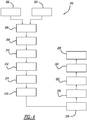
- FIG 4 illustrates a flow chart of a method 200 for fabricating the cast component 10 in accordance with an exemplary embodiment.
- Figure 5 is a perspective front view of a pattern 40 and ceramic matrix composite (CMC) elongated cores 42 and 44 for forming the cast component 10 (illustrated in Figures 1-3 ) during an early fabrication stage in accordance with an exemplary embodiment.
- the CMC elongated cores 42 and 44 are provided at step 202.
- the CMC elongated cores 42 and 44 are configured as relatively long and narrow rods, which may be non-linear and/or partially or substantially tortuous, each having an intermediate section 46 that is disposed between end sections 48 and 50.
- the end sections 48 and 50 extend from opposite ends of the intermediate section 48 in generally opposing directions that are transverse to the longitudinal direction(s) of the intermediate section 46.
- the multi-piece die may be preloaded with the ceramic fibers, such as, for example, a ceramic fiber preform and/or continuous strands of ceramic fibers (e.g., unidirectional), and the ceramic matrix-forming material may be injected into the multi-piece die to infiltrate the ceramic fibers with the ceramic matrix-forming material, and then the process continues by solidifying, removing, and firing or sintering to form the CMC elongated cores 42 and 44.
- the ceramic fibers such as, for example, a ceramic fiber preform and/or continuous strands of ceramic fibers (e.g., unidirectional)
- the ceramic matrix-forming material may be injected into the multi-piece die to infiltrate the ceramic fibers with the ceramic matrix-forming material, and then the process continues by solidifying, removing, and firing or sintering to form the CMC elongated cores 42 and 44.
- the pattern 40 is provided at step 204. As illustrated, the pattern 40 is similarly configured to the net shape or near net shape of the platform 14 of the cast component 10 illustrated in Figures 1-3 with the exception that the pattern 40 includes trenches 56 and 58 that are formed extending into an outer surface 57 of the pattern 40. As illustrated, the pattern 40 has tear-shaped openings 62 that correspond to the tear-shaped openings 24 illustrated in Figures 1-3 . The trenches 56 and 58 are positioned relative to the tear-shaped openings 62 substantially corresponding to the positioning of the cooling channels 32 and 34 relative to the tear-shaped openings 24 formed in the cast component 10 as illustrated in Figures 1-3 .
- the pattern 40 is absent features that correspond to the cooling apertures 20 and 22 in the cast component 10 (shown in Figures 1-3 ) since the cooling apertures 20 and 22 can be added by a post-machining process after the component 10 is cast due to the relatively short length and linear configuration of the cooling apertures 20 and 22.
- the pattern 40 is formed of a pattern-forming material 60 such as wax or a plastic material.
- the patterned 40 may be formed using conventional techniques such as by injecting the pattern-forming material 60, in a molten form, into a multi-piece die, followed by solidifying the pattern-forming material 60 to form the patterned 40, which is subsequently removed from the multi-piece die.
- the process continues by arranging the CMC elongated cores 42 and 44 in the pattern 40 at step 206.
- the CMC elongated cores 42 and 44 are positioned such that the intermediate sections 46 of the CMC elongated cores 42 and 44 are arranged in the trenches 56 and 58 extending generally parallel to and/or offset from the outer surface 57 of the pattern 40.
- the end sections 48 and 50 of the CMC elongated cores 42 and 44 extend in generally opposing directions transverse to the outer surface 57 of the pattern 40 such that the end sections 48 protrude outwardly from the outer surface 66 of the pattern 40 and the end sections 50 protrude outwardly from the outer surface 57 of the pattern 40.
- the intermediate sections 46 of the CMC elongated cores 42 and 44 are arranged laterally adjacent to their neighboring openings 62.
- the process continues by filling the remaining spaces in the trenches 56 and 58 with additional pattern-forming material 68 at step 208 to define a pattern-CMC elongated core arrangement 70.
- the remaining spaces in the trenches 56 and 58 between the CMC elongated cores 42 and 44 and the sidewalls of the pattern 40 that define the trenches 56 and 58 are filled with the additional pattern-forming material 68.
- the additional pattern-forming material 68 is wax that is formed into the remaining spaces in the trenches 56 and 58 using a manual process or an automated process.
- the process flows from steps 204 to 210 without steps 206 and 208.
- the process continues by assembling multiple pattern-CMC elongated core arrangements 70 into a conventional investment cast tree arrangement at step 210.
- shell molds 74 are formed over the pattern-CMC elongated core arrangements 70 to define a cavity 76 in each of the shell molds 74 at step 212.
- the shell molds 74 are formed by dipping the tree arrangement 72 in a ceramic slurry multiple times to build layers of the ceramic slurry material onto the pattern-CMC elongated core arrangements 70 and then allowing the ceramic slurry material to dry.
- the end sections 48 and 50 of the CMC elongated cores 42 and 44 protrude from the pattern(s) 40 and as such, the end sections 48 and 50 will be at least partially disposed in the walls of the shell molds 74 to help support the CMC elongated cores 42 and 44 in the cavities 76.
- the process continues by replacing the pattern-forming material(s) 60 and 68 with metal via the investment casting process to form the cast component 10 (see Figures 1-3 ) with the CMC elongated cores 42 and 44 disposed therein defining the cooling channels 32 and 34.
- the pattern-forming material(s) 60 and 68 is removed from the shell molds 74 at step 214.
- the pattern-forming material(s) 60 and 68 is removed from the shell molds 74 by melting out, washing out, and/or burning the pattern-forming material (s) 60 and 68 (e.g., wax) from the shell molds 74.
- the cavities 76 of the shell molds are substantially empty with the exception that the CMC elongated cores 42 and 44 are disposed in the open volume of the cavities 76 with the end sections 48 and 50 supportingly disposed in the walls of the shell molds 74.
- the shell molds 74 may then be baked, fired, and/or sintered at step 216 to increase the strength of the shell molds 74.
- the investment casting process is a single crystal casting process and the process continues by providing a seed crystal to each of the cavities 76 of the shell molds 74 at step 218.
- the shell molds 74 are then preheated to a predetermined temperature at step 220.
- the shell molds 74 are preheated to a temperature of from about 1350 to about 1550°C.
- the process continues by removing the CMC elongated cores 40 and 42 from the cast components 10 at step 226.
- the CMC elongated cores 40 and 42 are removed by leaching out or etching the CMC elongated cores 40 and 42 using a wet etching process to open the cooling channels 32 and 34 in the cast components 10 for fluid communication.
- the wet etching process includes a caustic material such as potassium hydroxide for removing the CMC elongated cores 40 and 42.
- the caps 84 Z fare J Z removed to allow a wet etchant, for example, to flow into the hollow passage 82 to facilitate or improve (e.g., increase) the etching rate and removal of the CMC elongated core 44.
- a wet etchant for example, to flow into the hollow passage 82 to facilitate or improve (e.g., increase) the etching rate and removal of the CMC elongated core 44.
- the CMC elongated core(s) can be solid or tubular and hollow depending upon the specific design and/or process conditions being used to form the cast component 10.
- the phrases "at least one of ⁇ A>, ⁇ B>, ... and ⁇ N>” or “at least one of ⁇ A>, ⁇ B>, ... ⁇ N>, or combinations thereof" or " ⁇ A>, ⁇ B>, ... and/or ⁇ N>” are defined by the Applicant in the broadest sense, superseding any other implied definitions hereinbefore or hereinafter unless expressly asserted by the Applicant to the contrary, to mean one or more elements selected from the group comprising A, B, ... and N.
- the phrases mean any combination of one or more of the elements A, B, ... or N including any one element alone or the one element in combination with one or more of the other elements which may also include, in combination, additional elements not listed.
Landscapes
- Engineering & Computer Science (AREA)
- Mechanical Engineering (AREA)
- Chemical & Material Sciences (AREA)
- Materials Engineering (AREA)
- Molds, Cores, And Manufacturing Methods Thereof (AREA)
Claims (14)
- Verfahren zur Herstellung eines Gussteils (10), aufweisend einen Kühlkanal (32, 34), der darin ausgebildet ist, wobei das Verfahren umfasst:Ausbilden einer Schalenform (74) über einer langgestreckten musterkeramischen Matrixverbundwerkstoff (CMC: ceramic matrix composite)-Kernanordnung (70), um einen Hohlraum (76) in der Schalenform (74) zu definieren, wobei die langgestreckte Muster-CMC-Kernanordnung (70) ein musterbildendes Material (60) mit einem langgestreckten CMC-Kern (42, 44) umfasst, der ein rohrförmiger langgestreckter Kern ist, der eine Wand (80) aufweist, die einen darin angeordneten hohlen Durchgang (82) umgibt;Ersetzen des musterbildenden Materials (60) in dem Hohlraum (76) durch Metall mittels eines Gießprozesses, um das Gussteil (10) mit dem darin angeordneten langgestreckten CMC-Kern (42, 44) zu bilden, wodurch der Kühlkanal (32, 34) definiert wird; undEntfernen des langgestreckten CMC-Kerns (42, 44) aus dem Gussteil (10), um den Kühlkanal (32, 34) für Fluidkommunikation zu öffnen,Ausbilden von Kappen über Enden des langgestreckten CMC-Kerns (42, 44) vor dem Ausbilden der Schalenform (74), um den hohlen Durchgang zu verschließen; undEntfernen der Kappen von den Enden des langgestreckten CMC-Kerns (42, 44) nach dem Ausbilden des Gussteils (10), um den hohlen Durchgang zu öffnen, und wobei Auslaugen oder Ätzen das Vorschieben eines Nassätzmittels in den hohlen Durchgang umfasst, um das Auslaugen und/oder Ätzen des langgestreckten CMC-Kerns (42, 44) zu erleichtern.
- Verfahren nach Anspruch 1, ferner umfassend das Ausbilden der langgestreckten Muster-CMC-Kernanordnung (70), umfassend:Bereitstellen eines Musters (40), umfassend das musterbildende Material (60) und aufweisend eine Vertiefung (56, 58), die in dem musterbildenden Material (60) ausgebildet ist; undAnordnen des langgestreckten CMC-Kerns (42, 44) in der Vertiefung (56, 58).
- Verfahren nach Anspruch 2, wobei das Muster (40) Wände aufweist, die die Vertiefung (56, 58) definieren, und wobei das Ausbilden der langgestreckten Muster-CMC-Kernanordnung (70) das Füllen von verbleibendem Raum in der Vertiefung (56, 58) zwischen dem langgestreckten CMC-Kern (42, 44) und den Wänden des Musters (40) mit zusätzlichem musterbildenden Material (68) umfasst, wobei das zusätzliche musterbildende Material (68) vorzugsweise Wachs ist.
- Verfahren nach einem der Ansprüche 2 bis 3, wobei der langgestreckte CMC-Kern (42, 44)
einen Zwischenabschnitt (46) aufweist, und wobei das Anordnen des langgestreckten CMC-Kerns (42, 44) in der Vertiefung (56, 58) das Anordnen des Zwischenabschnitts (46) des langgestreckten CMC-Kerns (42, 44), der sich im Allgemeinen parallel zu und/oder versetzt von einer benachbarten Außenfläche des Musters (40) erstreckt, in der Vertiefung (56, 58) umfasst; und/oder
einen ersten Endabschnitt (48) und einen zweiten Endabschnitt (50) aufweist, die sich von gegenüberliegenden Enden des Zwischenabschnitts (46) erstrecken, und wobei das Anordnen des langgestreckten CMC-Kerns (42, 44) in der Vertiefung (56, 58) das Anordnen des ersten (48) und zweiten (50) Endabschnitts, die sich in im Allgemeinen entgegengesetzten Richtungen quer zu der benachbarten Außenfläche (57, 66) des Musters (40) erstrecken, umfasst. - Verfahren nach Anspruch 4, wobei das Anordnen des langgestreckten CMC-Kerns (42, 44) in der Vertiefung (56, 58) das Anordnen des ersten Endabschnitts (48), der von der benachbarten Außenfläche (66) des Musters (40) vorsteht, und des zweiten Endabschnitts (50), der von einer gegenüberliegenden Außenfläche (57) des Musters (40), die auf einer der benachbarten Außenfläche (66) gegenüberliegenden Seite ausgerichtet ist, umfasst.
- Verfahren nach Ansprüchen 4 bis 5, wobei das Ausbilden der Schalenform (74) das Ausbilden der Schalenform (74) so umfasst, dass die ersten (48) und zweiten Endabschnitte (50) zumindest teilweise in Wänden der Schalenform (74) angeordnet sind.
- Verfahren nach einem der Ansprüche 2 bis 6, wobei das Muster (40) eine Öffnung (62) aufweist, die da hindurch ausgebildet ist und sich von einer benachbarten Außenfläche (66) zu einer gegenüberliegenden Außenfläche (57) erstreckt, und wobei das Anordnen des langgestreckten CMC-Kerns (42, 44) das Ausrichten eines Zwischenabschnitts (46) des langgestreckten CMC-Kerns (42, 44) in der Vertiefung (56, 58) benachbart zu der Öffnung (62) umfasst.
- Verfahren nach einem der vorhergehenden Ansprüche, wobei das Herstellen des Gussteils (10) das Ausbilden des Gussteils (10) als Gasturbinentriebwerksteil umfasst.
- Verfahren nach einem der vorhergehenden Ansprüche, wobei das musterbildende Material (60) Wachs oder Kunststoffmaterial umfasst.
- Verfahren nach einem der vorstehenden Ansprüche, ferner umfassend das Ausbilden der langgestreckten Muster-CMC-Kernanordnung (70), umfassend das Anordnen des langgestreckten CMC-Kerns (42, 44) in einem Muster (40), das das musterbildende Material (60) umfasst, wobei das Anordnen des langgestreckten CMC-Kerns (42, 44) im Muster (40) aufweist:Bereitstellen des langgestreckten CMC-Kerns (42, 44); undAusbilden und/oder Einspritzen des Musters (40) über dem langgestreckten CMC-Kern (42, 44).
- Verfahren nach einem der vorhergehenden Ansprüche, wobei der langgestreckte CMC-Kern (42, 44) eine keramische Matrix umfasst, die mit keramischen Fasern verstärkt ist, wobei vorzugsweise
der langgestreckte CMC-Kern (42, 44) eine keramische Matrix umfasst, die Siliziummetall, Silizium-Metall-Legierung, Siliziumkarbid, Siliziumnitrid, Zirkoniumdioxid, Aluminiumoxid oder Kombinationen davon umfasst,
die keramischen Fasern in einer Menge von 15 bis 50 Volumenprozent (Vol. %) des langgestreckten CMC-Kerns (42, 44) vorhanden sind, und/oder
die keramischen Fastern aus Aluminiumoxid, Mullit, Siliziumkarbid, Siliziumnitrid, Zirkoniumdioxid, Kohlenstoff oder Kombinationen davon hergestellt sind. - Verfahren nach einem der vorhergehenden Ansprüche, wobei das Ersetzen des musterbildenden Materials (60) in dem Hohlraum (76) durch Metall implementiert wird durch:Entfernen des musterbildenden Materials (60) von der Schalenform (74), während der langgestreckte CMC-Kern (42, 44) im Hohlraum (76) angeordnet bleibt; undFüllen des Hohlraums (76) mit geschmolzenem Metall und Verfestigen des geschmolzenen Metalls, um das Gussteil (10) mit dem darin angeordneten langgestreckten CMC-Kern (42, 44) zu bilden, wodurch der Kühlkanal (32, 34) definiert wird.
- Verfahren nach einem der vorhergehenden Ansprüche, wobei das Entfernen des langgestreckten CMC-Kerns (42, 44) aus dem Gussteil (10) durch Auslaugen oder Ätzen des langgestreckten CMC-Kerns (42, 44) durchgeführt wird, um den Kühlkanal (32, 34) im Gussteil (10) für die Fluidkommunikation zu öffnen.
- Verfahren nach einem der vorstehenden Ansprüche, wobei das Ersetzen des musterbildenden Materials (60) im Hohlraum (76) durch Metall mittels eines Gießprozesses, insbesondere das Füllen des Hohlraums (76) mit geschmolzenem Metall und das Verfestigen des geschmolzenen Metalls, das Ausbilden des Gussteils (10) unter Verwendung eines Einkristallgießprozesses umfasst, wobei das Ausbilden des Gießsteils (10) vorzugsweise das Vorheizen der Schalenform (74) auf eine Temperatur von etwa 1350 bis etwa 1550°C vor dem Füllen des Hohlraums (76) mit dem geschmolzenen Metall umfasst.
Applications Claiming Priority (1)
| Application Number | Priority Date | Filing Date | Title |
|---|---|---|---|
| US201662336856P | 2016-05-16 | 2016-05-16 |
Publications (2)
| Publication Number | Publication Date |
|---|---|
| EP3246108A1 EP3246108A1 (de) | 2017-11-22 |
| EP3246108B1 true EP3246108B1 (de) | 2021-03-03 |
Family
ID=58632862
Family Applications (1)
| Application Number | Title | Priority Date | Filing Date |
|---|---|---|---|
| EP17168131.5A Active EP3246108B1 (de) | 2016-05-16 | 2017-04-26 | Verfahren zur herstellung von gusskomponenten mit kühlkanälen |
Country Status (3)
| Country | Link |
|---|---|
| US (1) | US10933466B2 (de) |
| EP (1) | EP3246108B1 (de) |
| CA (1) | CA2967091C (de) |
Families Citing this family (1)
| Publication number | Priority date | Publication date | Assignee | Title |
|---|---|---|---|---|
| CN112313192A (zh) * | 2018-05-15 | 2021-02-02 | 赛峰集团 | Cmc零件的制造方法 |
Family Cites Families (11)
| Publication number | Priority date | Publication date | Assignee | Title |
|---|---|---|---|---|
| US4989664A (en) * | 1988-07-07 | 1991-02-05 | United Technologies Corporation | Core molding composition |
| US5273104A (en) * | 1991-09-20 | 1993-12-28 | United Technologies Corporation | Process for making cores used in investment casting |
| US5465780A (en) * | 1993-11-23 | 1995-11-14 | Alliedsignal Inc. | Laser machining of ceramic cores |
| US6029736A (en) | 1997-08-29 | 2000-02-29 | Howmet Research Corporation | Reinforced quartz cores for directional solidification casting processes |
| US20090000754A1 (en) * | 2007-06-27 | 2009-01-01 | United Technologies Corporation | Investment casting cores and methods |
| EP2445668A2 (de) * | 2009-06-26 | 2012-05-02 | Havasu | Verfahren zur formung von armaturen und befestigungen |
| WO2012118516A1 (en) * | 2010-05-17 | 2012-09-07 | General Electronic Company | Ceramic matrix composite structures, components formed therewith, and methods of producing |
| EP2463043A1 (de) * | 2010-12-08 | 2012-06-13 | Siemens Aktiengesellschaft | Keramisches Gussformteil mit verschiedenen Schrumpffaktoren und Gußverfahren |
| US8393381B2 (en) * | 2011-05-18 | 2013-03-12 | Pcc Airfoils, Inc. | Method of forming a cast metal article |
| WO2014138231A1 (en) | 2013-03-08 | 2014-09-12 | Rolls-Royce Corporation | Adaptive machining of components |
| US10507515B2 (en) * | 2014-12-15 | 2019-12-17 | United Technologies Corporation | Ceramic core for component casting |
-
2017
- 2017-04-26 EP EP17168131.5A patent/EP3246108B1/de active Active
- 2017-05-11 CA CA2967091A patent/CA2967091C/en active Active
- 2017-05-15 US US15/595,028 patent/US10933466B2/en active Active
Non-Patent Citations (1)
| Title |
|---|
| None * |
Also Published As
| Publication number | Publication date |
|---|---|
| CA2967091C (en) | 2023-07-11 |
| CA2967091A1 (en) | 2017-11-16 |
| US10933466B2 (en) | 2021-03-02 |
| EP3246108A1 (de) | 2017-11-22 |
| US20170326635A1 (en) | 2017-11-16 |
Similar Documents
| Publication | Publication Date | Title |
|---|---|---|
| US8251123B2 (en) | Casting core assembly methods | |
| EP1634665B1 (de) | Verbundkern zur Verwendung beim Feingiessen | |
| US9835035B2 (en) | Cast-in cooling features especially for turbine airfoils | |
| EP1914030B1 (de) | Feingusskerne und deren Anwendung beim Feingiessen | |
| EP2792771B1 (de) | Verfahren zur Herstellung von einkristallinen Bauteilen unter Verwendung einer Additivherstellung und Abschmelzen | |
| US4421153A (en) | Method of making an aerofoil member for a gas turbine engine | |
| CA2958064C (en) | Casting with first metal components and second metal components | |
| US20100025001A1 (en) | Methods for fabricating gas turbine components using an integrated disposable core and shell die | |
| EP2511024B1 (de) | Profilierter metallener gusskern | |
| US20080216983A1 (en) | Method for precision casting of metallic components with thin passage ducts | |
| US5498132A (en) | Improved hollow cast products such as gas-cooled gas turbine engine blades | |
| EP2564952B1 (de) | Poröser keramischer Körper und Verfahren dafür | |
| KR20060049907A (ko) | 인베스트먼트 주조 | |
| WO2012003439A1 (en) | Self supporting core-in-a-core for casting | |
| JP2011092996A (ja) | 機械工作用工具及び機械工作方法 | |
| EP3381582B1 (de) | Verfahren zum herstellen komplexer innerer hohlräume in turbinenschaufeln | |
| CN104619441B (zh) | 铸造模型 | |
| EP3210693B1 (de) | Herstellungsverfahren eines bauteils mit einer zweiten metallkomponente, die um eine erste metallkomponente geformt ist, unter verwendung von isostatischem pressen | |
| US10933466B2 (en) | Methods for fabricating cast components with cooling channels | |
| GB2465181A (en) | Casting turbine components using a shell casting mould having an integral core | |
| JP2010110795A (ja) | 一体型の使い捨て中子及びシェルダイを使用してガスタービン構成要素を製造する方法 | |
| EP3269470B1 (de) | Kernform | |
| EP3431206B1 (de) | Vorrichtung und verfahren zur feingusskernherstellung | |
| CA2643279A1 (en) | Methods for fabricating gas turbine components using an integrated disposable core and shell die | |
| HK1196331B (en) | Cast-in cooling features especially for turbine airfoils |
Legal Events
| Date | Code | Title | Description |
|---|---|---|---|
| PUAI | Public reference made under article 153(3) epc to a published international application that has entered the european phase |
Free format text: ORIGINAL CODE: 0009012 |
|
| STAA | Information on the status of an ep patent application or granted ep patent |
Free format text: STATUS: THE APPLICATION HAS BEEN PUBLISHED |
|
| AK | Designated contracting states |
Kind code of ref document: A1 Designated state(s): AL AT BE BG CH CY CZ DE DK EE ES FI FR GB GR HR HU IE IS IT LI LT LU LV MC MK MT NL NO PL PT RO RS SE SI SK SM TR |
|
| AX | Request for extension of the european patent |
Extension state: BA ME |
|
| STAA | Information on the status of an ep patent application or granted ep patent |
Free format text: STATUS: REQUEST FOR EXAMINATION WAS MADE |
|
| 17P | Request for examination filed |
Effective date: 20180518 |
|
| RBV | Designated contracting states (corrected) |
Designated state(s): AL AT BE BG CH CY CZ DE DK EE ES FI FR GB GR HR HU IE IS IT LI LT LU LV MC MK MT NL NO PL PT RO RS SE SI SK SM TR |
|
| STAA | Information on the status of an ep patent application or granted ep patent |
Free format text: STATUS: EXAMINATION IS IN PROGRESS |
|
| 17Q | First examination report despatched |
Effective date: 20190328 |
|
| GRAP | Despatch of communication of intention to grant a patent |
Free format text: ORIGINAL CODE: EPIDOSNIGR1 |
|
| STAA | Information on the status of an ep patent application or granted ep patent |
Free format text: STATUS: GRANT OF PATENT IS INTENDED |
|
| INTG | Intention to grant announced |
Effective date: 20200929 |
|
| GRAS | Grant fee paid |
Free format text: ORIGINAL CODE: EPIDOSNIGR3 |
|
| GRAA | (expected) grant |
Free format text: ORIGINAL CODE: 0009210 |
|
| STAA | Information on the status of an ep patent application or granted ep patent |
Free format text: STATUS: THE PATENT HAS BEEN GRANTED |
|
| AK | Designated contracting states |
Kind code of ref document: B1 Designated state(s): AL AT BE BG CH CY CZ DE DK EE ES FI FR GB GR HR HU IE IS IT LI LT LU LV MC MK MT NL NO PL PT RO RS SE SI SK SM TR |
|
| REG | Reference to a national code |
Ref country code: GB Ref legal event code: FG4D |
|
| REG | Reference to a national code |
Ref country code: AT Ref legal event code: REF Ref document number: 1366651 Country of ref document: AT Kind code of ref document: T Effective date: 20210315 Ref country code: CH Ref legal event code: EP |
|
| REG | Reference to a national code |
Ref country code: DE Ref legal event code: R096 Ref document number: 602017033643 Country of ref document: DE |
|
| REG | Reference to a national code |
Ref country code: IE Ref legal event code: FG4D |
|
| REG | Reference to a national code |
Ref country code: LT Ref legal event code: MG9D |
|
| PG25 | Lapsed in a contracting state [announced via postgrant information from national office to epo] |
Ref country code: HR Free format text: LAPSE BECAUSE OF FAILURE TO SUBMIT A TRANSLATION OF THE DESCRIPTION OR TO PAY THE FEE WITHIN THE PRESCRIBED TIME-LIMIT Effective date: 20210303 Ref country code: GR Free format text: LAPSE BECAUSE OF FAILURE TO SUBMIT A TRANSLATION OF THE DESCRIPTION OR TO PAY THE FEE WITHIN THE PRESCRIBED TIME-LIMIT Effective date: 20210604 Ref country code: FI Free format text: LAPSE BECAUSE OF FAILURE TO SUBMIT A TRANSLATION OF THE DESCRIPTION OR TO PAY THE FEE WITHIN THE PRESCRIBED TIME-LIMIT Effective date: 20210303 Ref country code: NO Free format text: LAPSE BECAUSE OF FAILURE TO SUBMIT A TRANSLATION OF THE DESCRIPTION OR TO PAY THE FEE WITHIN THE PRESCRIBED TIME-LIMIT Effective date: 20210603 Ref country code: LT Free format text: LAPSE BECAUSE OF FAILURE TO SUBMIT A TRANSLATION OF THE DESCRIPTION OR TO PAY THE FEE WITHIN THE PRESCRIBED TIME-LIMIT Effective date: 20210303 Ref country code: BG Free format text: LAPSE BECAUSE OF FAILURE TO SUBMIT A TRANSLATION OF THE DESCRIPTION OR TO PAY THE FEE WITHIN THE PRESCRIBED TIME-LIMIT Effective date: 20210603 |
|
| REG | Reference to a national code |
Ref country code: NL Ref legal event code: MP Effective date: 20210303 |
|
| REG | Reference to a national code |
Ref country code: AT Ref legal event code: MK05 Ref document number: 1366651 Country of ref document: AT Kind code of ref document: T Effective date: 20210303 |
|
| PG25 | Lapsed in a contracting state [announced via postgrant information from national office to epo] |
Ref country code: LV Free format text: LAPSE BECAUSE OF FAILURE TO SUBMIT A TRANSLATION OF THE DESCRIPTION OR TO PAY THE FEE WITHIN THE PRESCRIBED TIME-LIMIT Effective date: 20210303 Ref country code: RS Free format text: LAPSE BECAUSE OF FAILURE TO SUBMIT A TRANSLATION OF THE DESCRIPTION OR TO PAY THE FEE WITHIN THE PRESCRIBED TIME-LIMIT Effective date: 20210303 Ref country code: PL Free format text: LAPSE BECAUSE OF FAILURE TO SUBMIT A TRANSLATION OF THE DESCRIPTION OR TO PAY THE FEE WITHIN THE PRESCRIBED TIME-LIMIT Effective date: 20210303 Ref country code: SE Free format text: LAPSE BECAUSE OF FAILURE TO SUBMIT A TRANSLATION OF THE DESCRIPTION OR TO PAY THE FEE WITHIN THE PRESCRIBED TIME-LIMIT Effective date: 20210303 |
|
| PG25 | Lapsed in a contracting state [announced via postgrant information from national office to epo] |
Ref country code: NL Free format text: LAPSE BECAUSE OF FAILURE TO SUBMIT A TRANSLATION OF THE DESCRIPTION OR TO PAY THE FEE WITHIN THE PRESCRIBED TIME-LIMIT Effective date: 20210303 |
|
| PG25 | Lapsed in a contracting state [announced via postgrant information from national office to epo] |
Ref country code: SM Free format text: LAPSE BECAUSE OF FAILURE TO SUBMIT A TRANSLATION OF THE DESCRIPTION OR TO PAY THE FEE WITHIN THE PRESCRIBED TIME-LIMIT Effective date: 20210303 Ref country code: AT Free format text: LAPSE BECAUSE OF FAILURE TO SUBMIT A TRANSLATION OF THE DESCRIPTION OR TO PAY THE FEE WITHIN THE PRESCRIBED TIME-LIMIT Effective date: 20210303 Ref country code: CZ Free format text: LAPSE BECAUSE OF FAILURE TO SUBMIT A TRANSLATION OF THE DESCRIPTION OR TO PAY THE FEE WITHIN THE PRESCRIBED TIME-LIMIT Effective date: 20210303 Ref country code: EE Free format text: LAPSE BECAUSE OF FAILURE TO SUBMIT A TRANSLATION OF THE DESCRIPTION OR TO PAY THE FEE WITHIN THE PRESCRIBED TIME-LIMIT Effective date: 20210303 |
|
| REG | Reference to a national code |
Ref country code: DE Ref legal event code: R119 Ref document number: 602017033643 Country of ref document: DE |
|
| PG25 | Lapsed in a contracting state [announced via postgrant information from national office to epo] |
Ref country code: SK Free format text: LAPSE BECAUSE OF FAILURE TO SUBMIT A TRANSLATION OF THE DESCRIPTION OR TO PAY THE FEE WITHIN THE PRESCRIBED TIME-LIMIT Effective date: 20210303 Ref country code: RO Free format text: LAPSE BECAUSE OF FAILURE TO SUBMIT A TRANSLATION OF THE DESCRIPTION OR TO PAY THE FEE WITHIN THE PRESCRIBED TIME-LIMIT Effective date: 20210303 Ref country code: PT Free format text: LAPSE BECAUSE OF FAILURE TO SUBMIT A TRANSLATION OF THE DESCRIPTION OR TO PAY THE FEE WITHIN THE PRESCRIBED TIME-LIMIT Effective date: 20210705 Ref country code: IS Free format text: LAPSE BECAUSE OF FAILURE TO SUBMIT A TRANSLATION OF THE DESCRIPTION OR TO PAY THE FEE WITHIN THE PRESCRIBED TIME-LIMIT Effective date: 20210703 |
|
| PG25 | Lapsed in a contracting state [announced via postgrant information from national office to epo] |
Ref country code: LU Free format text: LAPSE BECAUSE OF NON-PAYMENT OF DUE FEES Effective date: 20210426 |
|
| PLBE | No opposition filed within time limit |
Free format text: ORIGINAL CODE: 0009261 |
|
| STAA | Information on the status of an ep patent application or granted ep patent |
Free format text: STATUS: NO OPPOSITION FILED WITHIN TIME LIMIT |
|
| REG | Reference to a national code |
Ref country code: BE Ref legal event code: MM Effective date: 20210430 |
|
| PG25 | Lapsed in a contracting state [announced via postgrant information from national office to epo] |
Ref country code: MC Free format text: LAPSE BECAUSE OF FAILURE TO SUBMIT A TRANSLATION OF THE DESCRIPTION OR TO PAY THE FEE WITHIN THE PRESCRIBED TIME-LIMIT Effective date: 20210303 Ref country code: LI Free format text: LAPSE BECAUSE OF NON-PAYMENT OF DUE FEES Effective date: 20210430 Ref country code: CH Free format text: LAPSE BECAUSE OF NON-PAYMENT OF DUE FEES Effective date: 20210430 Ref country code: AL Free format text: LAPSE BECAUSE OF FAILURE TO SUBMIT A TRANSLATION OF THE DESCRIPTION OR TO PAY THE FEE WITHIN THE PRESCRIBED TIME-LIMIT Effective date: 20210303 Ref country code: DE Free format text: LAPSE BECAUSE OF NON-PAYMENT OF DUE FEES Effective date: 20211103 Ref country code: DK Free format text: LAPSE BECAUSE OF FAILURE TO SUBMIT A TRANSLATION OF THE DESCRIPTION OR TO PAY THE FEE WITHIN THE PRESCRIBED TIME-LIMIT Effective date: 20210303 Ref country code: ES Free format text: LAPSE BECAUSE OF FAILURE TO SUBMIT A TRANSLATION OF THE DESCRIPTION OR TO PAY THE FEE WITHIN THE PRESCRIBED TIME-LIMIT Effective date: 20210303 |
|
| 26N | No opposition filed |
Effective date: 20211206 |
|
| GBPC | Gb: european patent ceased through non-payment of renewal fee |
Effective date: 20210603 |
|
| PG25 | Lapsed in a contracting state [announced via postgrant information from national office to epo] |
Ref country code: SI Free format text: LAPSE BECAUSE OF FAILURE TO SUBMIT A TRANSLATION OF THE DESCRIPTION OR TO PAY THE FEE WITHIN THE PRESCRIBED TIME-LIMIT Effective date: 20210303 |
|
| PG25 | Lapsed in a contracting state [announced via postgrant information from national office to epo] |
Ref country code: IT Free format text: LAPSE BECAUSE OF FAILURE TO SUBMIT A TRANSLATION OF THE DESCRIPTION OR TO PAY THE FEE WITHIN THE PRESCRIBED TIME-LIMIT Effective date: 20210303 Ref country code: IE Free format text: LAPSE BECAUSE OF NON-PAYMENT OF DUE FEES Effective date: 20210426 Ref country code: GB Free format text: LAPSE BECAUSE OF NON-PAYMENT OF DUE FEES Effective date: 20210603 |
|
| PG25 | Lapsed in a contracting state [announced via postgrant information from national office to epo] |
Ref country code: IS Free format text: LAPSE BECAUSE OF FAILURE TO SUBMIT A TRANSLATION OF THE DESCRIPTION OR TO PAY THE FEE WITHIN THE PRESCRIBED TIME-LIMIT Effective date: 20210703 |
|
| PG25 | Lapsed in a contracting state [announced via postgrant information from national office to epo] |
Ref country code: BE Free format text: LAPSE BECAUSE OF NON-PAYMENT OF DUE FEES Effective date: 20210430 |
|
| PG25 | Lapsed in a contracting state [announced via postgrant information from national office to epo] |
Ref country code: HU Free format text: LAPSE BECAUSE OF FAILURE TO SUBMIT A TRANSLATION OF THE DESCRIPTION OR TO PAY THE FEE WITHIN THE PRESCRIBED TIME-LIMIT; INVALID AB INITIO Effective date: 20170426 |
|
| PG25 | Lapsed in a contracting state [announced via postgrant information from national office to epo] |
Ref country code: CY Free format text: LAPSE BECAUSE OF FAILURE TO SUBMIT A TRANSLATION OF THE DESCRIPTION OR TO PAY THE FEE WITHIN THE PRESCRIBED TIME-LIMIT Effective date: 20210303 |
|
| P01 | Opt-out of the competence of the unified patent court (upc) registered |
Effective date: 20230528 |
|
| PG25 | Lapsed in a contracting state [announced via postgrant information from national office to epo] |
Ref country code: MK Free format text: LAPSE BECAUSE OF FAILURE TO SUBMIT A TRANSLATION OF THE DESCRIPTION OR TO PAY THE FEE WITHIN THE PRESCRIBED TIME-LIMIT Effective date: 20210303 |
|
| PG25 | Lapsed in a contracting state [announced via postgrant information from national office to epo] |
Ref country code: MT Free format text: LAPSE BECAUSE OF FAILURE TO SUBMIT A TRANSLATION OF THE DESCRIPTION OR TO PAY THE FEE WITHIN THE PRESCRIBED TIME-LIMIT Effective date: 20210303 |
|
| PGFP | Annual fee paid to national office [announced via postgrant information from national office to epo] |
Ref country code: FR Payment date: 20250424 Year of fee payment: 9 |
|
| PG25 | Lapsed in a contracting state [announced via postgrant information from national office to epo] |
Ref country code: TR Free format text: LAPSE BECAUSE OF FAILURE TO SUBMIT A TRANSLATION OF THE DESCRIPTION OR TO PAY THE FEE WITHIN THE PRESCRIBED TIME-LIMIT Effective date: 20210303 |