EP3246094B1 - Centrifuge rotor core with partial channels - Google Patents
Centrifuge rotor core with partial channels Download PDFInfo
- Publication number
- EP3246094B1 EP3246094B1 EP17172086.5A EP17172086A EP3246094B1 EP 3246094 B1 EP3246094 B1 EP 3246094B1 EP 17172086 A EP17172086 A EP 17172086A EP 3246094 B1 EP3246094 B1 EP 3246094B1
- Authority
- EP
- European Patent Office
- Prior art keywords
- rotor core
- channels
- rotor
- separation
- length
- Prior art date
- Legal status (The legal status is an assumption and is not a legal conclusion. Google has not performed a legal analysis and makes no representation as to the accuracy of the status listed.)
- Active
Links
Images





Classifications
-
- B—PERFORMING OPERATIONS; TRANSPORTING
- B04—CENTRIFUGAL APPARATUS OR MACHINES FOR CARRYING-OUT PHYSICAL OR CHEMICAL PROCESSES
- B04B—CENTRIFUGES
- B04B7/00—Elements of centrifuges
- B04B7/08—Rotary bowls
-
- B—PERFORMING OPERATIONS; TRANSPORTING
- B04—CENTRIFUGAL APPARATUS OR MACHINES FOR CARRYING-OUT PHYSICAL OR CHEMICAL PROCESSES
- B04B—CENTRIFUGES
- B04B1/00—Centrifuges with rotary bowls provided with solid jackets for separating predominantly liquid mixtures with or without solid particles
-
- B—PERFORMING OPERATIONS; TRANSPORTING
- B04—CENTRIFUGAL APPARATUS OR MACHINES FOR CARRYING-OUT PHYSICAL OR CHEMICAL PROCESSES
- B04B—CENTRIFUGES
- B04B5/00—Other centrifuges
- B04B5/04—Radial chamber apparatus for separating predominantly liquid mixtures, e.g. butyrometers
- B04B5/0442—Radial chamber apparatus for separating predominantly liquid mixtures, e.g. butyrometers with means for adding or withdrawing liquid substances during the centrifugation, e.g. continuous centrifugation
-
- B—PERFORMING OPERATIONS; TRANSPORTING
- B04—CENTRIFUGAL APPARATUS OR MACHINES FOR CARRYING-OUT PHYSICAL OR CHEMICAL PROCESSES
- B04B—CENTRIFUGES
- B04B7/00—Elements of centrifuges
- B04B7/08—Rotary bowls
- B04B7/12—Inserts, e.g. armouring plates
-
- B—PERFORMING OPERATIONS; TRANSPORTING
- B04—CENTRIFUGAL APPARATUS OR MACHINES FOR CARRYING-OUT PHYSICAL OR CHEMICAL PROCESSES
- B04B—CENTRIFUGES
- B04B5/00—Other centrifuges
- B04B5/04—Radial chamber apparatus for separating predominantly liquid mixtures, e.g. butyrometers
- B04B5/0442—Radial chamber apparatus for separating predominantly liquid mixtures, e.g. butyrometers with means for adding or withdrawing liquid substances during the centrifugation, e.g. continuous centrifugation
- B04B2005/0464—Radial chamber apparatus for separating predominantly liquid mixtures, e.g. butyrometers with means for adding or withdrawing liquid substances during the centrifugation, e.g. continuous centrifugation with hollow or massive core in centrifuge bowl
Definitions
- the present disclosure is related to centrifuge rotor cores. More particularly, the present disclosure is related to centrifuge rotor cores having partial channels.
- the particles typically are cells, subcellular organelles, viruses, virus like particles and macromolecules, such as DNA fragments.
- a centrifugation process is routinely used to perform the separation of these components from a solution.
- tube rotor centrifugation which employs a rotor that rotates or spins one or more tubes containing the one or more desired analytes for separation. While useful for separation of small volumes as may be needed for laboratory use during product development, the use of such tube rotor centrifugation techniques may not be considered to be rapid enough and/or to be cost effective enough for certain uses such as those common in a production environment. Thus, tube rotor centrifugation techniques have generally not proven to be easily scalable from the benchtop or lab environment to the production environment.
- Another common centrifugation technique is continuous flow centrifugation, which employs a rotor and rotor core that rotates or spins as the desired analyte or analytes flow continually over a density gradient maintained within the rotor assembly.
- Such continuous flow centrifugation techniques can include various different process steps including, but not limited to static gradient loading, static gradient unloading, loading of an unmixed or discontinuous gradient, loading of a layered or step gradient, dynamic gradient loading, dynamic gradient unloading, loading of mixed or linear or continuous gradients, and any combinations thereof.
- continuous flow centrifugation can, in some instances, be configured for linear scalability, for separations of different volumes or quantities, e.g., from laboratory scale to pilot scale to industrial scale or from industrial scale pilot scales to laboratory scale, using the same or similar centrifugation systems.
- the method and apparatus allow the same centrifuge systems can be used for sedimentation processes of multiple scales while maintaining substantially the same separation characteristics for each process by, at least in part, interchanging different sized and configured rotor cores within the rotor housing.
- JP S62 53756 A discloses a rotor core for a centrifuge according to the preamble of claim 1.
- the rotor cores disclosed herein which include a partial channel, provide enhancements and improvements to the prior art scalable continuous flow centrifugation.
- a rotor core is provided that has a plurality of partial channels, namely channels that extend less than an entire length of the rotor core.
- a rotor assembly has an outer housing with a removable rotor core disposed therein.
- the rotor core has a plurality of partial channels, namely channels that extend less than an entire length of the rotor core.
- a method for achieving a linear scale separation of particles of a product during centrifugation includes operating a centrifuge apparatus at certain predetermined parameters depending upon a product to be separated; placing a first rotor core in a rotor housing to define a first rotor assembly having a first volume capacity; rotating the first rotor assembly in the centrifuge apparatus and so as to achieve a first particle separation of the product; removing the first rotor core from the rotor housing and placing a second rotor core in the rotor housing to define a second rotor assembly having a second volume capacity; and rotating the second rotor assembly in the centrifuge apparatus so as to achieve a second particle separation of the product which is a linear scale with respect to the first particle separation.
- the first and second rotor cores have a common rotor length and each have a plurality of channels with a channel length.
- the channel length of at least one of the first and second cores being less than the common rotor length. Additionally, the channel length of the plurality of channels of the first rotor core is different than the channel length of the plurality of channels of the second rotor core.
- centrifuge apparatus 10 according to the present disclosure is shown in use with an exemplary embodiment of rotor core 12 having a plurality of separation channels 14 defined therein.
- rotor core 12 allows centrifuge apparatus 10 to be utilized in a process for separating components of a product sample in which the volume of the product sample can be scaled up or down while maintaining substantially the same selected separation parameters of the process or to enable one centrifuge to be used for multiple scale processes that do not necessarily need to be scaleable but should have a similar functioning process.
- rotor core 12 has channels 14 with a channel length (C L ) that extends less than an overall length of the rotor core, referred to herein as a rotor length (R L ).
- rotor cores 12 of the present disclosure are referred to as having "partial channels", namely having channels 14 that extend less than the entire length of the rotor core.
- channel length (C L ) is between 5% and 90% of rotor length (R L ), preferably between 20% and 80%, with between 25% and 75% being most preferred, and any subranges between these ranges.
- Rotor core 12 has channels 14 with a channel width (C W ) - where the channel width (C W ) and channel length (C L ), as well as the number of channels, define the volume of the rotor core. Since the present disclosure provides rotor cores 12 having partial channels 14, the channel width (C W ) is increased to provide the same volume as rotor cores having longer channels. Stated another way, by providing rotor cores 12 having channels 14 of partial or limited channel length (C L ), the rotor cores have increased or wider channel widths (C W ). As used herein, the channel width (C W ) is defined as a measurement of arc length of channel 14 at the outer diameter of rotor core 12.
- rotor cores 12 of the present disclosure - that have partial channels 14 - provide increased stability of the separation gradient during rotation by centrifuge apparatus 10.
- partial channels 14 of the present disclosure are shorter than the channels of the prior art and assuming a common channel volume, result in wider channels than those of the prior art. It is believed that the short, wide partial channels 14 of the present disclosure provide increased stability of the separation gradient during rotation by centrifuge apparatus 10.
- rotor core 12 has an aspect ratio of channel width (C W ) to channel length (C L ) from 10:1 to 1:10, preferably 1:1 to 1:10, more preferably from 1:1 to 1:5, with 1:1 to 1:3 being most preferred, and any subranges there between.
- Centrifuge 10 includes a tank assembly within which is housed a drive motor 16 and a rotor assembly 18.
- Drive motor 16 is used to spin rotor assembly 18 at speeds sufficient for separation of the desired analyte or analytes.
- Rotor assembly 18 includes an outer rotor housing 20 with removable rotor core 12 positioned therein.
- Housing 20 includes a central portion 22 and a pair of end caps 24, 26. At least one of end caps 24, 26 is selectively removable from central portion 22 so as to allow rotor core 12 to be inserted or removed from housing 20. In some embodiments, one of end caps 24, 26 can be permanently connected to or integrally formed with the central portion 22.
- centrifuge apparatus 10 can include a lift assembly 28 to raise one or more of drive motor 16 and the rotor assembly 18. Additionally, centrifuge apparatus 10 can include a console assembly 30, which is in communication with drive motor 16 and, when present, lift assembly 28 to control the respective functions thereof.
- rotor cores 12 having channels 14 of differing channel lengths (C L ) can be received in rotor assembly 18 and the rotor assembly can be installed in the centrifuge apparatus 10 to process - preferably in a linearly scalable manner - differing volumes of analyte or analytes.
- rotor assembly 18 includes an insert 32 at a first face 34 and/or a second face 36 of rotor core 12.
- insert 32 is removable in a bore 38 of rotor core 12 located by a pair of pins 40, a spring 42, and a seal or O-ring 44.
- Spring 42 normally biases insert 32 upwards along pins 40 away from faces 34, 36. In this manner, insert 32 can assist in seating rotor core 12 in housing 20 and end caps 24, 26 in a desired manner.
- rotor core 12 is illustrated in FIG. 2 having insert 32 at both faces 34, 36, it is contemplated by the present disclosure for the rotor core to have at least one of the inserts integrally formed therewith as illustrated in FIGS. 5-6 . Without wishing to be bound by any particular theory, it is believed by the present disclosure that rotor core 12 having integral insert 32 at least at one of faces 34, 36, improved flow through rotor assembly 18 by eliminating a region of reduced flow (i.e., dead leg) that can form around the insert. Although not illustrated, it is contemplated by the present disclosure for both inserts 32 to be integral to rotor core 12.
- FIG. 5 A first exemplary embodiment of the flow path through rotor core 12 of FIG. 3 is illustrated in FIG. 5 , and an alternate, opposite flow path through the rotor core is illustrated in FIG. 6 .
- Rotor core 12 of FIGS. 3-4 and 5-6 includes a flow path defined by an axial channel 44, a plurality of radial channels 46, the plurality of separation channels 14, a plurality of face channels 48, and, when insert 32 is present, a plurality of insert channels 50.
- the number of separation channels 14 is common with the number of radial and face channels 46, 48.
- the core includes any desired number of face channels 48 such as six or less channels, more preferably four channels.
- centrifuge apparatus 10 can be operated so that the flow of analyte or analytes through the flow path enters rotor core 12 at insert 32 proximate face 36, passes axially through the rotor core via axial channel 44, passes radially through the rotor core via radial channels 46, and enters separation channels 14.
- separation channels 14 which include a density gradient, any unseparated analyte or analytes and/or flow through passes over face 34 via face channels 48, then over insert 32 via insert channels 50 before exiting rotor assembly 18.
- core 12 includes a port or opening 52 connecting radial channels 46 and separation channels 14 that includes a taper such that the port is wider at an interface with separation channels 14.
- the taper of port 52 when the flow path is as illustrated in FIG. 6 , spreads the particles in the analyte or analytes across a greater area of the separation gradient, which can mitigate the impact of the particles on the gradient and maintain the separation performance (e.g., stability) of the gradient.
- the momentum of the analyte or analytes and/or flow through traveling radially outward can physically disrupt or cut through the gradient in separation channels 14.
- the taper of port 52 is believed to lessen this effect by spreading the momentum across a larger area of the gradient.
- radial channels 46 are illustrated as being perpendicular to an axis of rotation (A) of rotor core 12.
- radial channels 46 it is contemplated by the present disclosure for radial channels 46 to be angled with respect to a normal line (N) through the axis (A).
- radial channels 46 it is contemplated by the present disclosure for radial channels 46 to be angled with respect to the normal line (A) by between ⁇ 30 degrees, more preferably between ⁇ 10 degrees, with ⁇ 5 degrees being most preferred, and any subranges therebetween.
- the angle of radial channels 46 can be used to slow or reduce the momentum with which the analyte or analytes and/or flow through impacts the gradient in separation channels 14.
- the momentum of flow through radial channels 46 of FIG. 6 can be slowed by providing the radial channels with a downward angle with respect to normal line (A).
- centrifuge apparatus 10 can be operated so that the flow of analyte through the flow path enters rotor core 12 at insert 32 proximate face 34.
- the flow of analyte or analytes passes over insert 32 via insert channels 50, passes over face 34 via face channels 48, where the flow enters separation channels 14.
- separation channels 14 which include a centrifugation gradient, any unseparated analyte or analytes and/or flow through enters rotor core 12 via radial channels 46, flows into radial channel 44, and exits rotor core 12 at insert 32 at face 36.
- rotor core 112 has the same geometry and dimensions including rotor length (R L ) and channel width (C W ) as rotor core 12 shown in FIGS. 3 through 6 .
- rotor core 112 has partial channels 114 with have a channel length (C L ) that results in a volume of rotor core 112 that is 100 ml.
- rotor assembly 18 in centrifuge assembly 10 can be easily scaled, in a linear manner, by starting with the rotor core 12 of FIGS. 3 through 6 that has a volume of 50 ml, then using the rotor core 112 of FIGS. 7 through 10 that has a volume of 100 ml.
- rotor cores 12 and 112 which have three separation channels 14, 114.
- rotor cores it is contemplated by the present disclosure for rotor cores to have any desired number of separation channels.
- rotor core 212 includes six partial channels 214 with have a channel length (C L ) that is 25% of rotor length (R L ). Further, it is contemplated by the present disclosure for rotor core 212 to have any desired channel length (C L ) that is less than rotor length (R L ).
- Rotor core 212 of FIGS. 11 through 14 has partial channels 214 and can be compared to the prior art rotor core 212' shown in FIG. 15 .
- Rotor core 212' is commercially available from the Applicant under the tradename PK3-400.
- rotor core 212 and rotor core 212' have a common rotor volume of 400ml.
- rotor core 212 has partial channels 214 with channel length (C L ) that is less than the rotor length (R L ).
- the prior art rotor core 212' has channels 214' with a channel length (C L ) that is equal to the rotor length (R L ) - namely lacks the partial channels of the present disclosure.
- channels 212 have a channel width (C W ) that is substantially wider than the channel width (C W ) of rotor core 212' but have the same volume.
- FIG. 16 is a graph comparing the performance of rotor core 212 to the performance of the prior art rotor core 212'.
- rotor core 212 was configured with the flow direction illustrated in FIG. 5 .
- the standardized parameters for both tests include use of a commercially available PKII ultracentrifuge, a rotor speed of 35,000 rpm, a separation gradient that includes 200ml load volume of 55% w/w sucrose solution and 200ml load volume of water.
- the gradient collected from both tests illustrate a collection that is considered, for the purposes of the present application, linear with respect to one another.
- the results of the comparison in FIG. 16 illustrate linearity between the separation using the prior art rotor core 212' that has full length channels 214' and rotor core 212 that has the shorter, wider partial channels 214 according to the present disclosure.
- Rotor core 314 illustrates an example of radial channels 346 that are angled - by a positive angle - with respect to a normal line (A).
- Rotor core 314 includes a tapered region 354 within channels 314. Tapered region 354 can be used to provide further scalability to the volume of rotor core 314.
- axial channels 346 have ports 352 at the interface with separation channels 314 that terminate in the tapered region. Additionally and without wishing to be bound by any particular theory, termination of ports 352 in tapered region 354 is believed to reduce or mitigate effects of momentum of the analyte or analytes and/or flow through on the gradient in channels 314.
Landscapes
- Centrifugal Separators (AREA)
Description
- The present disclosure is related to centrifuge rotor cores. More particularly, the present disclosure is related to centrifuge rotor cores having partial channels.
- In the biological and chemical sciences, there is often a need to separate particulate matter suspended in a solution. In a biological experiment, for example, the particles typically are cells, subcellular organelles, viruses, virus like particles and macromolecules, such as DNA fragments. A centrifugation process is routinely used to perform the separation of these components from a solution.
- One common centrifugation technique is tube rotor centrifugation, which employs a rotor that rotates or spins one or more tubes containing the one or more desired analytes for separation. While useful for separation of small volumes as may be needed for laboratory use during product development, the use of such tube rotor centrifugation techniques may not be considered to be rapid enough and/or to be cost effective enough for certain uses such as those common in a production environment. Thus, tube rotor centrifugation techniques have generally not proven to be easily scalable from the benchtop or lab environment to the production environment.
- Another common centrifugation technique is continuous flow centrifugation, which employs a rotor and rotor core that rotates or spins as the desired analyte or analytes flow continually over a density gradient maintained within the rotor assembly. Such continuous flow centrifugation techniques can include various different process steps including, but not limited to static gradient loading, static gradient unloading, loading of an unmixed or discontinuous gradient, loading of a layered or step gradient, dynamic gradient loading, dynamic gradient unloading, loading of mixed or linear or continuous gradients, and any combinations thereof.
- As disclosed in
U.S. Publication No. 2003/0114289A1 , continuous flow centrifugation can, in some instances, be configured for linear scalability, for separations of different volumes or quantities, e.g., from laboratory scale to pilot scale to industrial scale or from industrial scale pilot scales to laboratory scale, using the same or similar centrifugation systems. The method and apparatus allow the same centrifuge systems can be used for sedimentation processes of multiple scales while maintaining substantially the same separation characteristics for each process by, at least in part, interchanging different sized and configured rotor cores within the rotor housing. - The prior art document
JP S62 53756 A claim 1. - It has been determined by the present disclosure that the rotor cores disclosed herein, which include a partial channel, provide enhancements and improvements to the prior art scalable continuous flow centrifugation.
- A rotor core is provided that has a plurality of partial channels, namely channels that extend less than an entire length of the rotor core.
- A rotor assembly is provided that has an outer housing with a removable rotor core disposed therein. The rotor core has a plurality of partial channels, namely channels that extend less than an entire length of the rotor core.
- A method for achieving a linear scale separation of particles of a product during centrifugation is provided. The method includes operating a centrifuge apparatus at certain predetermined parameters depending upon a product to be separated; placing a first rotor core in a rotor housing to define a first rotor assembly having a first volume capacity; rotating the first rotor assembly in the centrifuge apparatus and so as to achieve a first particle separation of the product; removing the first rotor core from the rotor housing and placing a second rotor core in the rotor housing to define a second rotor assembly having a second volume capacity; and rotating the second rotor assembly in the centrifuge apparatus so as to achieve a second particle separation of the product which is a linear scale with respect to the first particle separation. The first and second rotor cores have a common rotor length and each have a plurality of channels with a channel length. The channel length of at least one of the first and second cores being less than the common rotor length. Additionally, the channel length of the plurality of channels of the first rotor core is different than the channel length of the plurality of channels of the second rotor core.
- The above-described and other features and advantages of the present disclosure will be appreciated and understood by those skilled in the art from the following detailed description, drawings, and appended claims.
-
-
FIG. 1 is a front elevational view of a centrifuge apparatus according to the present disclosure; -
FIG. 2 is a sectional view of an exemplary embodiment of a rotor assembly according to the present disclosure; -
FIG. 3 is a top perspective view of an exemplary embodiment of a rotor core according to the present disclosure; -
FIG. 4 is a partially exploded view of the rotor core according ofFIG. 3 ; -
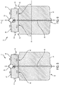
FIG. 5 is a schematic view of an exemplary embodiment of a flow path through the rotor core ofFIG. 3 ; -
FIG. 6 is a schematic view of another exemplary embodiment of a flow path through the rotor core ofFIG. 3 ; -
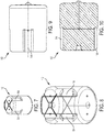
FIG. 7 is a top perspective view of an alternate exemplary embodiment of a rotor core according to the present disclosure; -
FIG. 8 is a view of the rotor core ofFIG. 7 illustrating flow channels; -
FIG. 9 is a side view of the rotor core ofFIG. 7 ; -
FIG. 10 is a sectional view of the rotor core ofFIG. 7 ; -
FIG. 11 is a top perspective view of another alternate exemplary embodiment of a rotor core according to the present disclosure; -
FIG. 12 is a view of the rotor core ofFIG. 11 illustrating flow channels; -
FIG. 13 is a side view of the rotor core ofFIG. 11 ; -
FIG. 14 is a sectional view of the rotor core ofFIG. 11 ; -
FIG. 15 is a top perspective view of a prior art rotor core used to compare to the rotor core ofFIG. 11 ; -
FIG. 16 is a graph comparing the performance of the rotor core as inFIG. 11 andFIG. 15 ; -
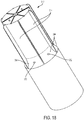
FIG. 17 is a bottom perspective view of yet another alternate exemplary embodiment of a rotor core according to the present disclosure; -
FIG. 18 is a top perspective view of the rotor core ofFIG. 17 ; and -
FIG. 19 is a view of the rotor core ofFIG. 17 illustrating flow channels. - Referring to the drawings and in particular with simultaneous reference to
FIGS. 1-4 , acentrifuge apparatus 10 according to the present disclosure is shown in use with an exemplary embodiment ofrotor core 12 having a plurality ofseparation channels 14 defined therein. - Advantageously,
rotor core 12 allowscentrifuge apparatus 10 to be utilized in a process for separating components of a product sample in which the volume of the product sample can be scaled up or down while maintaining substantially the same selected separation parameters of the process or to enable one centrifuge to be used for multiple scale processes that do not necessarily need to be scaleable but should have a similar functioning process. - According to the present
disclosure rotor core 12 haschannels 14 with a channel length (CL) that extends less than an overall length of the rotor core, referred to herein as a rotor length (RL). Thus,rotor cores 12 of the present disclosure are referred to as having "partial channels", namely havingchannels 14 that extend less than the entire length of the rotor core. In some embodiments, channel length (CL) is between 5% and 90% of rotor length (RL), preferably between 20% and 80%, with between 25% and 75% being most preferred, and any subranges between these ranges. - Exchanging a
rotor core 12 havingchannels 14 of a first partial channel length (CL) incentrifuge assembly 10 with arotor core 12 havingchannels 14 of a second channel length (CL) - where the second channel length is longer or shorter than the first - allows different volumes of analyte or analytes to be processed in a linearly scaled essentially similar manner. -
Rotor core 12 haschannels 14 with a channel width (CW) - where the channel width (CW) and channel length (CL), as well as the number of channels, define the volume of the rotor core. Since the present disclosure providesrotor cores 12 havingpartial channels 14, the channel width (CW) is increased to provide the same volume as rotor cores having longer channels. Stated another way, by providingrotor cores 12 havingchannels 14 of partial or limited channel length (CL), the rotor cores have increased or wider channel widths (CW). As used herein, the channel width (CW) is defined as a measurement of arc length ofchannel 14 at the outer diameter ofrotor core 12. - Without wishing to be bound by any particular theory, it is believed that
rotor cores 12 of the present disclosure - that have partial channels 14 - provide increased stability of the separation gradient during rotation bycentrifuge apparatus 10. Simply stated,partial channels 14 of the present disclosure are shorter than the channels of the prior art and assuming a common channel volume, result in wider channels than those of the prior art. It is believed that the short, widepartial channels 14 of the present disclosure provide increased stability of the separation gradient during rotation bycentrifuge apparatus 10. - It is also believed that increased gradient stability provides an environment where the density gradient 'profile' can be retained for a substantially longer period of time and therefore allow for a process to be conducted where the analyte or analytes can be successfully collected and the gradient remain in an essentially similar profile as compared to each other. This means that the analyte or analytes accumulation and resolution of impurities remains essentially the same for either scale of operation hence they are of a linear scale.
- In some embodiments,
rotor core 12 has an aspect ratio of channel width (CW) to channel length (CL) from 10:1 to 1:10, preferably 1:1 to 1:10, more preferably from 1:1 to 1:5, with 1:1 to 1:3 being most preferred, and any subranges there between. -
Centrifuge 10 includes a tank assembly within which is housed adrive motor 16 and arotor assembly 18. Drivemotor 16 is used to spinrotor assembly 18 at speeds sufficient for separation of the desired analyte or analytes. -
Rotor assembly 18 includes anouter rotor housing 20 withremovable rotor core 12 positioned therein.Housing 20 includes acentral portion 22 and a pair ofend caps end caps central portion 22 so as to allowrotor core 12 to be inserted or removed fromhousing 20. In some embodiments, one ofend caps central portion 22. - In some embodiments,
centrifuge apparatus 10 can include alift assembly 28 to raise one or more ofdrive motor 16 and therotor assembly 18. Additionally,centrifuge apparatus 10 can include aconsole assembly 30, which is in communication withdrive motor 16 and, when present,lift assembly 28 to control the respective functions thereof. - In this manner,
rotor cores 12 havingchannels 14 of differing channel lengths (CL) can be received inrotor assembly 18 and the rotor assembly can be installed in thecentrifuge apparatus 10 to process - preferably in a linearly scalable manner - differing volumes of analyte or analytes. - In some embodiments,
rotor assembly 18 includes aninsert 32 at afirst face 34 and/or asecond face 36 ofrotor core 12. In the illustrated embodiment, insert 32 is removable in abore 38 ofrotor core 12 located by a pair ofpins 40, aspring 42, and a seal or O-ring 44.Spring 42 normally biases insert 32 upwards alongpins 40 away from faces 34, 36. In this manner, insert 32 can assist inseating rotor core 12 inhousing 20 andend caps - While
rotor core 12 is illustrated inFIG. 2 havinginsert 32 at both faces 34, 36, it is contemplated by the present disclosure for the rotor core to have at least one of the inserts integrally formed therewith as illustrated inFIGS. 5-6 . Without wishing to be bound by any particular theory, it is believed by the present disclosure thatrotor core 12 havingintegral insert 32 at least at one offaces rotor assembly 18 by eliminating a region of reduced flow (i.e., dead leg) that can form around the insert. Although not illustrated, it is contemplated by the present disclosure for bothinserts 32 to be integral torotor core 12. - A first exemplary embodiment of the flow path through
rotor core 12 ofFIG. 3 is illustrated inFIG. 5 , and an alternate, opposite flow path through the rotor core is illustrated inFIG. 6 . -
Rotor core 12 ofFIGS. 3-4 and5-6 includes a flow path defined by anaxial channel 44, a plurality ofradial channels 46, the plurality ofseparation channels 14, a plurality offace channels 48, and, wheninsert 32 is present, a plurality ofinsert channels 50. Preferably, the number ofseparation channels 14 is common with the number of radial and facechannels core 12 to not includeinsert 32 and here, the core includes any desired number offace channels 48 such as six or less channels, more preferably four channels. - As shown in
FIG. 6 ,centrifuge apparatus 10 can be operated so that the flow of analyte or analytes through the flow path entersrotor core 12 atinsert 32proximate face 36, passes axially through the rotor core viaaxial channel 44, passes radially through the rotor core viaradial channels 46, and entersseparation channels 14. After passing throughseparation channels 14, which include a density gradient, any unseparated analyte or analytes and/or flow through passes overface 34 viaface channels 48, then overinsert 32 viainsert channels 50 before exitingrotor assembly 18. - Preferably,
core 12 includes a port or opening 52 connectingradial channels 46 andseparation channels 14 that includes a taper such that the port is wider at an interface withseparation channels 14. Without wishing to be bound by any particular theory, the taper ofport 52, when the flow path is as illustrated inFIG. 6 , spreads the particles in the analyte or analytes across a greater area of the separation gradient, which can mitigate the impact of the particles on the gradient and maintain the separation performance (e.g., stability) of the gradient. Simply, it is believed that the momentum of the analyte or analytes and/or flow through traveling radially outward can physically disrupt or cut through the gradient inseparation channels 14. The taper ofport 52 is believed to lessen this effect by spreading the momentum across a larger area of the gradient. - It should be recognized that
radial channels 46 are illustrated as being perpendicular to an axis of rotation (A) ofrotor core 12. Of course, it is contemplated by the present disclosure forradial channels 46 to be angled with respect to a normal line (N) through the axis (A). For example, it is contemplated by the present disclosure forradial channels 46 to be angled with respect to the normal line (A) by between ±30 degrees, more preferably between ± 10 degrees, with ±5 degrees being most preferred, and any subranges therebetween. - Again without wishing to be bound by any particular theory, it is believed that the angle of
radial channels 46 can be used to slow or reduce the momentum with which the analyte or analytes and/or flow through impacts the gradient inseparation channels 14. For example, the momentum of flow throughradial channels 46 ofFIG. 6 can be slowed by providing the radial channels with a downward angle with respect to normal line (A). - Conversely and as shown in
FIG. 5 ,centrifuge apparatus 10 can be operated so that the flow of analyte through the flow path entersrotor core 12 atinsert 32proximate face 34. Here the flow of analyte or analytes passes overinsert 32 viainsert channels 50, passes overface 34 viaface channels 48, where the flow entersseparation channels 14. After passing throughseparation channels 14, which include a centrifugation gradient, any unseparated analyte or analytes and/or flow through entersrotor core 12 viaradial channels 46, flows intoradial channel 44, and exitsrotor core 12 atinsert 32 atface 36. - Referring now to
FIGS. 7 through 10 , another alternate embodiment ofrotor core 112 is shown. Here,rotor core 112 has the same geometry and dimensions including rotor length (RL) and channel width (CW) asrotor core 12 shown inFIGS. 3 through 6 . However,rotor core 112 haspartial channels 114 with have a channel length (CL) that results in a volume ofrotor core 112 that is 100 ml. - Accordingly, it can be seen that use of
rotor assembly 18 incentrifuge assembly 10 can be easily scaled, in a linear manner, by starting with therotor core 12 ofFIGS. 3 through 6 that has a volume of 50 ml, then using therotor core 112 ofFIGS. 7 through 10 that has a volume of 100 ml. - It should be recognized that the present disclosure is illustrated above with respect to
rotor cores separation channels - For example, and referring to
FIGS. 11 through 14 , another alternate embodiment ofrotor core 212 is shown. Here,rotor core 212 includes sixpartial channels 214 with have a channel length (CL) that is 25% of rotor length (RL). Further, it is contemplated by the present disclosure forrotor core 212 to have any desired channel length (CL) that is less than rotor length (RL). -
Rotor core 212 ofFIGS. 11 through 14 haspartial channels 214 and can be compared to the prior art rotor core 212' shown inFIG. 15 . Rotor core 212' is commercially available from the Applicant under the tradename PK3-400. - For ease of comparison,
rotor core 212 and rotor core 212' have a common rotor volume of 400ml. Here,rotor core 212 haspartial channels 214 with channel length (CL) that is less than the rotor length (RL). By contrast, the prior art rotor core 212' has channels 214' with a channel length (CL) that is equal to the rotor length (RL) - namely lacks the partial channels of the present disclosure. As a result,channels 212 have a channel width (CW) that is substantially wider than the channel width (CW) of rotor core 212' but have the same volume. -
FIG. 16 is a graph comparing the performance ofrotor core 212 to the performance of the prior art rotor core 212'. During the comparison test,rotor core 212 was configured with the flow direction illustrated inFIG. 5 . The standardized parameters for both tests include use of a commercially available PKII ultracentrifuge, a rotor speed of 35,000 rpm, a separation gradient that includes 200ml load volume of 55% w/w sucrose solution and 200ml load volume of water. - As can be seen from
FIG. 16 , the gradient collected from both tests illustrate a collection that is considered, for the purposes of the present application, linear with respect to one another. Thus, the results of the comparison inFIG. 16 illustrate linearity between the separation using the prior art rotor core 212' that has full length channels 214' androtor core 212 that has the shorter, widerpartial channels 214 according to the present disclosure. - More features of the partial channel rotor cores of the present disclosure are disclosed with respect to
FIGS. 17 through 19 .Rotor core 314 illustrates an example ofradial channels 346 that are angled - by a positive angle - with respect to a normal line (A). -
Rotor core 314 includes a taperedregion 354 withinchannels 314.Tapered region 354 can be used to provide further scalability to the volume ofrotor core 314. - In some embodiments,
axial channels 346 haveports 352 at the interface withseparation channels 314 that terminate in the tapered region. Additionally and without wishing to be bound by any particular theory, termination ofports 352 in taperedregion 354 is believed to reduce or mitigate effects of momentum of the analyte or analytes and/or flow through on the gradient inchannels 314. - It should also be noted that the terms "first", "second", "third", "upper", "lower", and the like may be used herein to modify various elements. These modifiers do not imply a spatial, sequential, or hierarchical order to the modified elements unless specifically stated.
- While the present disclosure has been described with reference to one or more exemplary embodiments, it will be understood by those skilled in the art that various changes may be made and equivalents may be substituted for elements thereof without departing from the scope of the present disclosure. In addition, many modifications may be made to adapt a particular situation or material to the teachings of the disclosure without departing from the scope thereof. Therefore, it is intended that the present disclosure not be limited to the particular embodiment(s) disclosed as the best mode contemplated, but that the disclosure will include all embodiments falling within the scope of the appended claims.
Claims (15)
- A rotor core (12, 112, 212, 312) for a centrifuge comprising:a rotor length (RL) defined along an axis of rotation (A) of the rotor core (12),an axial channel (44) defined through the axis of rotation,a plurality of separation channels (14, 114, 214, 314), anda plurality of radial channels (46, 346),characterized in that:the axial channel (44) extends along the axis of rotation a distance that is less than the rotor length (RL),the plurality of separation channels (14, 114, 214, 314) have a channel length (CL) extending along the axis of rotation (A) a distance that is less than the rotor length (RL); andthe plurality of radial channels (46, 346) pass radially through the rotor core from the axial channel (44) to the plurality of separation channels (14, 114, 214, 314) respectively.
- The rotor core (12, 112, 212, 312) of claim 1, wherein the channel length (CL) is between 5% and 90% of the rotor length (RL).
- The rotor core (12, 112, 212, 312) of either claim 1 or 2, wherein the plurality of separation channels (14, 114, 214, 314) have a channel width (CW), the rotor core (12) comprising an aspect ratio of the channel width (CW) to the channel length (CL) from 10:1 to 1:10.
- The rotor core (12, 112, 212, 312) of claim 1, further comprising a first end face and a second end face, the plurality of separation channels intersecting with only one of the first and second end faces.
- The rotor core (12, 112, 212, 312) of any of claims 1 to 3, wherein the first and/or second end face (34, 36) comprises an insert (32) that is integral to the first and/or second end face (34, 36) and/or is connected to, but biased away from, the first and/or second end face (34, 36).
- The rotor core (12, 112, 212, 312) of any one of the preceding claims, further comprising a flow path defined by an axial channel (44), a plurality of radial channels (46, 346), the plurality of separation channels (14, 114, 214, 314), a plurality of face channels (48),
the plurality of face channels (48) being defined in the first end face (34) and connecting an inlet or outlet flow to the plurality of separation channels (14, 114, 214, 314),
the plurality of separation channels (14, 114, 214, 314) connecting the plurality of face channels (48) to the plurality of radial channels (46, 346),
the plurality of radial channels (46, 346) connecting the plurality of separation channels (14) to the axial channel (44), the axial channel (44) being defined through the axis of rotation (A), and
the axial channel (44) connecting the plurality of radial channels (46) to the second end face (36). - The rotor core (12, 112, 212, 312) of claim 5, wherein the first end face (34) comprises a first insert (32), the flow path further comprising a plurality of insert channels (50), the plurality of insert channels (50) connecting the plurality of face channels (48) to the inlet or outlet flow.
- The rotor core (12, 112, 212, 312) of either claim 5 or 6, further comprising a port (52) connecting the plurality of radial channels (46, 346) and the plurality of separation channels (14, 114, 214, 314), the port (52) having a taper such that the port is wider at an interface with the plurality of separation channels (14, 114, 214, 314) than at the plurality of radial channels (46, 346).
- The rotor core (12, 112, 212, 312) of any one of claims 5 through 7, wherein the plurality of radial channels (46, 346) are perpendicular to the axis of rotation (A) or are angled with respect to a normal line (N) through the axis of rotation (A).
- The rotor core (312) of any one of claims 5 through 8, wherein the plurality of separation channels (314) comprise a tapered region (354).
- The rotor core (312) of claim 9, further comprising a tapered port (352) connecting the plurality of separation channels (314) to a flow path, the tapered port (352) being defined in the tapered region (354) of the plurality of separation channels (314).
- A rotor assembly (18) comprising the rotor core (12, 112, 212, 312) of any one of claims 1 through 10 removably disposed in an outer housing (20).
- The rotor assembly (18) of claim 11, further comprising:
a second rotor core (12, 112, 212, 312) removably disposable in the outer housing (20), the second rotor core (12, 112, 212, 312) being rotatable in the outer housing (12) about the axis of rotation (A), the second rotor core (12, 112, 212, 312) having the rotor length (RL), the second rotor core (12, 112, 212, 312) having a plurality of second separation channels (14, 114, 214, 314) having a second channel length (CL) that extends along the axis of rotation (A) less than the rotor length (RL), wherein the channel length (CL) of the plurality of separation channels (14, 114, 214, 314) of the first rotor core (12, 112, 212, 312) is different than the second channel length (CL). - The rotor assembly (18) of either claim 11 or 12, wherein the plurality of separation channels (14, 114, 214, 314) of the first rotor core (12, 112, 212, 312) have a first channel width (CW) and the plurality of separation channels (14, 114, 214, 314) of the second rotor core (12, 112, 212, 312) have a second channel width (CW), wherein the first channel width (CW) is the same as or different from the second channel width (CW).
- A method for achieving a linear scale separation of particles of a product during centrifugation, comprising:selecting a first rotor core (12, 112, 212, 312) and a second rotor core (12, 112, 212, 312) that have a common rotor length (RL) and each have a plurality of separation channels (14, 114, 214, 314) with a channel length (CL), the channel length (CL) of at least one of the first and second cores (12, 112, 212, 312) being less than the common rotor length (RL), and the channel length (CL) of the plurality of channels (14, 114, 214, 314) of the first rotor core being different than the channel length (CL) of the plurality of channels (14, 114, 214, 314) of the second rotor core (12, 112, 212, 312);placing the first rotor core (12, 112, 212, 312) in a rotor housing (20) to define a first rotor assembly (18) having a first volume capacity;rotating the first rotor assembly (18) about a rotation axis to achieve a first particle separation of the first volume of the product;removing the first rotor core (12, 112, 212, 312) from the rotor housing (20) and placing the second rotor core (12, 112, 212, 312) in the rotor housing (20) to define a second rotor assembly (18) having a second volume capacity, the second volume capacity being different than the first volume capacity; androtating the second rotor assembly (18) about the rotation axis to achieve a second particle separation of the second volume of the product which is a linear with respect to the first particle separation.
Applications Claiming Priority (1)
| Application Number | Priority Date | Filing Date | Title |
|---|---|---|---|
| US201662338563P | 2016-05-19 | 2016-05-19 |
Publications (2)
| Publication Number | Publication Date |
|---|---|
| EP3246094A1 EP3246094A1 (en) | 2017-11-22 |
| EP3246094B1 true EP3246094B1 (en) | 2020-07-08 |
Family
ID=58738991
Family Applications (1)
| Application Number | Title | Priority Date | Filing Date |
|---|---|---|---|
| EP17172086.5A Active EP3246094B1 (en) | 2016-05-19 | 2017-05-19 | Centrifuge rotor core with partial channels |
Country Status (3)
| Country | Link |
|---|---|
| US (2) | US10751733B2 (en) |
| EP (1) | EP3246094B1 (en) |
| CN (1) | CN107398358B (en) |
Family Cites Families (9)
| Publication number | Priority date | Publication date | Assignee | Title |
|---|---|---|---|---|
| US3498531A (en) * | 1968-02-16 | 1970-03-03 | Beckman Instruments Inc | Continuous flow ultracentrifuge |
| US3556967A (en) * | 1968-08-29 | 1971-01-19 | Atomic Energy Commission | Electrophoretic separation utilizing liquid centrifuge |
| US3730422A (en) * | 1971-05-25 | 1973-05-01 | Atomic Energy Commission | Continuous flow centrifuge with means for reducing pressure drop |
| JPS6253756A (en) * | 1985-08-30 | 1987-03-09 | Hitachi Koki Co Ltd | Rotor for centrifugal separator |
| US4842738A (en) * | 1988-04-29 | 1989-06-27 | Greenspan Harvey P | Centrifuge device |
| US6312610B1 (en) * | 1998-07-13 | 2001-11-06 | Phase Inc. | Density screening outer wall transport method for fluid separation devices |
| US20030114289A1 (en) * | 2001-11-27 | 2003-06-19 | Merino Sandra Patricia | Centrifuge with removable core for scalable centrifugation |
| AU2012250459B2 (en) * | 2011-05-05 | 2015-06-04 | Stemcell Technologies Canada Inc. | Method and insert for density gradient separation |
| NL2013662B1 (en) * | 2014-10-21 | 2016-10-05 | Evodos B V | Centrifugal separator, cartridge unit therefor. |
-
2017
- 2017-05-18 CN CN201710351666.5A patent/CN107398358B/en active Active
- 2017-05-19 US US15/599,722 patent/US10751733B2/en active Active
- 2017-05-19 EP EP17172086.5A patent/EP3246094B1/en active Active
-
2020
- 2020-07-08 US US16/923,675 patent/US11389810B2/en active Active
Non-Patent Citations (1)
| Title |
|---|
| None * |
Also Published As
| Publication number | Publication date |
|---|---|
| US20170333917A1 (en) | 2017-11-23 |
| US10751733B2 (en) | 2020-08-25 |
| EP3246094A1 (en) | 2017-11-22 |
| US20200338573A1 (en) | 2020-10-29 |
| CN107398358B (en) | 2020-04-21 |
| CN107398358A (en) | 2017-11-28 |
| US11389810B2 (en) | 2022-07-19 |
Similar Documents
| Publication | Publication Date | Title |
|---|---|---|
| EP3902630B1 (en) | Multi-dimensional double spiral device and methods of use thereof | |
| EP1450961B1 (en) | Centrifuge with removable core for scalable centrifugation | |
| DE102010041621B4 (en) | Method for transporting magnetic particles | |
| EP2378266B1 (en) | Particle separation and concentration system | |
| EP0686199A1 (en) | Centrifugal method and apparatus for isolating a substance from a mixture | |
| EP3638420A1 (en) | Nucleic acid extraction and purification cartridges | |
| EP1957972A1 (en) | Plasma separation on a disc like device | |
| US11389810B2 (en) | Centrifuge rotor core with partial channels | |
| Park et al. | Electrokinetic enhancement of membrane techniques for efficient nanoparticle separation and preconcentration | |
| US7846394B2 (en) | Apparatus and method for separating particles within a specimen | |
| AU2014277687B2 (en) | Method for sized-based cell separation using spinning membrane filtration | |
| KR20210102776A (en) | Multifunctional microfluidic apparatus for cfDNA separation, concentration and amplification and detection method using the same | |
| US20100012575A1 (en) | Channel Filter Having Surface Topology For Filtering Micro Particles And Method For Manufacturing Same | |
| Schimpf | Experimental field-flow fractionation: overview |
Legal Events
| Date | Code | Title | Description |
|---|---|---|---|
| PUAI | Public reference made under article 153(3) epc to a published international application that has entered the european phase |
Free format text: ORIGINAL CODE: 0009012 |
|
| STAA | Information on the status of an ep patent application or granted ep patent |
Free format text: STATUS: THE APPLICATION HAS BEEN PUBLISHED |
|
| AK | Designated contracting states |
Kind code of ref document: A1 Designated state(s): AL AT BE BG CH CY CZ DE DK EE ES FI FR GB GR HR HU IE IS IT LI LT LU LV MC MK MT NL NO PL PT RO RS SE SI SK SM TR |
|
| AX | Request for extension of the european patent |
Extension state: BA ME |
|
| STAA | Information on the status of an ep patent application or granted ep patent |
Free format text: STATUS: REQUEST FOR EXAMINATION WAS MADE |
|
| 17P | Request for examination filed |
Effective date: 20180522 |
|
| RBV | Designated contracting states (corrected) |
Designated state(s): AL AT BE BG CH CY CZ DE DK EE ES FI FR GB GR HR HU IE IS IT LI LT LU LV MC MK MT NL NO PL PT RO RS SE SI SK SM TR |
|
| STAA | Information on the status of an ep patent application or granted ep patent |
Free format text: STATUS: EXAMINATION IS IN PROGRESS |
|
| 17Q | First examination report despatched |
Effective date: 20190531 |
|
| GRAP | Despatch of communication of intention to grant a patent |
Free format text: ORIGINAL CODE: EPIDOSNIGR1 |
|
| STAA | Information on the status of an ep patent application or granted ep patent |
Free format text: STATUS: GRANT OF PATENT IS INTENDED |
|
| INTG | Intention to grant announced |
Effective date: 20191217 |
|
| GRAS | Grant fee paid |
Free format text: ORIGINAL CODE: EPIDOSNIGR3 |
|
| GRAA | (expected) grant |
Free format text: ORIGINAL CODE: 0009210 |
|
| STAA | Information on the status of an ep patent application or granted ep patent |
Free format text: STATUS: THE PATENT HAS BEEN GRANTED |
|
| AK | Designated contracting states |
Kind code of ref document: B1 Designated state(s): AL AT BE BG CH CY CZ DE DK EE ES FI FR GB GR HR HU IE IS IT LI LT LU LV MC MK MT NL NO PL PT RO RS SE SI SK SM TR |
|
| REG | Reference to a national code |
Ref country code: CH Ref legal event code: EP Ref country code: AT Ref legal event code: REF Ref document number: 1287872 Country of ref document: AT Kind code of ref document: T Effective date: 20200715 |
|
| REG | Reference to a national code |
Ref country code: DE Ref legal event code: R096 Ref document number: 602017019247 Country of ref document: DE |
|
| REG | Reference to a national code |
Ref country code: IE Ref legal event code: FG4D |
|
| REG | Reference to a national code |
Ref country code: NL Ref legal event code: FP |
|
| REG | Reference to a national code |
Ref country code: LT Ref legal event code: MG4D |
|
| REG | Reference to a national code |
Ref country code: AT Ref legal event code: MK05 Ref document number: 1287872 Country of ref document: AT Kind code of ref document: T Effective date: 20200708 |
|
| PG25 | Lapsed in a contracting state [announced via postgrant information from national office to epo] |
Ref country code: ES Free format text: LAPSE BECAUSE OF FAILURE TO SUBMIT A TRANSLATION OF THE DESCRIPTION OR TO PAY THE FEE WITHIN THE PRESCRIBED TIME-LIMIT Effective date: 20200708 Ref country code: LT Free format text: LAPSE BECAUSE OF FAILURE TO SUBMIT A TRANSLATION OF THE DESCRIPTION OR TO PAY THE FEE WITHIN THE PRESCRIBED TIME-LIMIT Effective date: 20200708 Ref country code: PT Free format text: LAPSE BECAUSE OF FAILURE TO SUBMIT A TRANSLATION OF THE DESCRIPTION OR TO PAY THE FEE WITHIN THE PRESCRIBED TIME-LIMIT Effective date: 20201109 Ref country code: BG Free format text: LAPSE BECAUSE OF FAILURE TO SUBMIT A TRANSLATION OF THE DESCRIPTION OR TO PAY THE FEE WITHIN THE PRESCRIBED TIME-LIMIT Effective date: 20201008 Ref country code: AT Free format text: LAPSE BECAUSE OF FAILURE TO SUBMIT A TRANSLATION OF THE DESCRIPTION OR TO PAY THE FEE WITHIN THE PRESCRIBED TIME-LIMIT Effective date: 20200708 Ref country code: SE Free format text: LAPSE BECAUSE OF FAILURE TO SUBMIT A TRANSLATION OF THE DESCRIPTION OR TO PAY THE FEE WITHIN THE PRESCRIBED TIME-LIMIT Effective date: 20200708 Ref country code: GR Free format text: LAPSE BECAUSE OF FAILURE TO SUBMIT A TRANSLATION OF THE DESCRIPTION OR TO PAY THE FEE WITHIN THE PRESCRIBED TIME-LIMIT Effective date: 20201009 Ref country code: NO Free format text: LAPSE BECAUSE OF FAILURE TO SUBMIT A TRANSLATION OF THE DESCRIPTION OR TO PAY THE FEE WITHIN THE PRESCRIBED TIME-LIMIT Effective date: 20201008 Ref country code: HR Free format text: LAPSE BECAUSE OF FAILURE TO SUBMIT A TRANSLATION OF THE DESCRIPTION OR TO PAY THE FEE WITHIN THE PRESCRIBED TIME-LIMIT Effective date: 20200708 Ref country code: FI Free format text: LAPSE BECAUSE OF FAILURE TO SUBMIT A TRANSLATION OF THE DESCRIPTION OR TO PAY THE FEE WITHIN THE PRESCRIBED TIME-LIMIT Effective date: 20200708 |
|
| PG25 | Lapsed in a contracting state [announced via postgrant information from national office to epo] |
Ref country code: RS Free format text: LAPSE BECAUSE OF FAILURE TO SUBMIT A TRANSLATION OF THE DESCRIPTION OR TO PAY THE FEE WITHIN THE PRESCRIBED TIME-LIMIT Effective date: 20200708 Ref country code: LV Free format text: LAPSE BECAUSE OF FAILURE TO SUBMIT A TRANSLATION OF THE DESCRIPTION OR TO PAY THE FEE WITHIN THE PRESCRIBED TIME-LIMIT Effective date: 20200708 Ref country code: PL Free format text: LAPSE BECAUSE OF FAILURE TO SUBMIT A TRANSLATION OF THE DESCRIPTION OR TO PAY THE FEE WITHIN THE PRESCRIBED TIME-LIMIT Effective date: 20200708 Ref country code: IS Free format text: LAPSE BECAUSE OF FAILURE TO SUBMIT A TRANSLATION OF THE DESCRIPTION OR TO PAY THE FEE WITHIN THE PRESCRIBED TIME-LIMIT Effective date: 20201108 |
|
| REG | Reference to a national code |
Ref country code: DE Ref legal event code: R097 Ref document number: 602017019247 Country of ref document: DE |
|
| PG25 | Lapsed in a contracting state [announced via postgrant information from national office to epo] |
Ref country code: IT Free format text: LAPSE BECAUSE OF FAILURE TO SUBMIT A TRANSLATION OF THE DESCRIPTION OR TO PAY THE FEE WITHIN THE PRESCRIBED TIME-LIMIT Effective date: 20200708 Ref country code: EE Free format text: LAPSE BECAUSE OF FAILURE TO SUBMIT A TRANSLATION OF THE DESCRIPTION OR TO PAY THE FEE WITHIN THE PRESCRIBED TIME-LIMIT Effective date: 20200708 Ref country code: SM Free format text: LAPSE BECAUSE OF FAILURE TO SUBMIT A TRANSLATION OF THE DESCRIPTION OR TO PAY THE FEE WITHIN THE PRESCRIBED TIME-LIMIT Effective date: 20200708 Ref country code: RO Free format text: LAPSE BECAUSE OF FAILURE TO SUBMIT A TRANSLATION OF THE DESCRIPTION OR TO PAY THE FEE WITHIN THE PRESCRIBED TIME-LIMIT Effective date: 20200708 Ref country code: DK Free format text: LAPSE BECAUSE OF FAILURE TO SUBMIT A TRANSLATION OF THE DESCRIPTION OR TO PAY THE FEE WITHIN THE PRESCRIBED TIME-LIMIT Effective date: 20200708 Ref country code: CZ Free format text: LAPSE BECAUSE OF FAILURE TO SUBMIT A TRANSLATION OF THE DESCRIPTION OR TO PAY THE FEE WITHIN THE PRESCRIBED TIME-LIMIT Effective date: 20200708 |
|
| PLBE | No opposition filed within time limit |
Free format text: ORIGINAL CODE: 0009261 |
|
| STAA | Information on the status of an ep patent application or granted ep patent |
Free format text: STATUS: NO OPPOSITION FILED WITHIN TIME LIMIT |
|
| PG25 | Lapsed in a contracting state [announced via postgrant information from national office to epo] |
Ref country code: AL Free format text: LAPSE BECAUSE OF FAILURE TO SUBMIT A TRANSLATION OF THE DESCRIPTION OR TO PAY THE FEE WITHIN THE PRESCRIBED TIME-LIMIT Effective date: 20200708 |
|
| 26N | No opposition filed |
Effective date: 20210409 |
|
| PG25 | Lapsed in a contracting state [announced via postgrant information from national office to epo] |
Ref country code: SK Free format text: LAPSE BECAUSE OF FAILURE TO SUBMIT A TRANSLATION OF THE DESCRIPTION OR TO PAY THE FEE WITHIN THE PRESCRIBED TIME-LIMIT Effective date: 20200708 |
|
| PG25 | Lapsed in a contracting state [announced via postgrant information from national office to epo] |
Ref country code: SI Free format text: LAPSE BECAUSE OF FAILURE TO SUBMIT A TRANSLATION OF THE DESCRIPTION OR TO PAY THE FEE WITHIN THE PRESCRIBED TIME-LIMIT Effective date: 20200708 |
|
| REG | Reference to a national code |
Ref country code: CH Ref legal event code: PL |
|
| PG25 | Lapsed in a contracting state [announced via postgrant information from national office to epo] |
Ref country code: CH Free format text: LAPSE BECAUSE OF NON-PAYMENT OF DUE FEES Effective date: 20210531 Ref country code: LU Free format text: LAPSE BECAUSE OF NON-PAYMENT OF DUE FEES Effective date: 20210519 Ref country code: LI Free format text: LAPSE BECAUSE OF NON-PAYMENT OF DUE FEES Effective date: 20210531 Ref country code: MC Free format text: LAPSE BECAUSE OF FAILURE TO SUBMIT A TRANSLATION OF THE DESCRIPTION OR TO PAY THE FEE WITHIN THE PRESCRIBED TIME-LIMIT Effective date: 20200708 |
|
| REG | Reference to a national code |
Ref country code: BE Ref legal event code: MM Effective date: 20210531 |
|
| PG25 | Lapsed in a contracting state [announced via postgrant information from national office to epo] |
Ref country code: IE Free format text: LAPSE BECAUSE OF NON-PAYMENT OF DUE FEES Effective date: 20210519 |
|
| PG25 | Lapsed in a contracting state [announced via postgrant information from national office to epo] |
Ref country code: BE Free format text: LAPSE BECAUSE OF NON-PAYMENT OF DUE FEES Effective date: 20210531 |
|
| PG25 | Lapsed in a contracting state [announced via postgrant information from national office to epo] |
Ref country code: HU Free format text: LAPSE BECAUSE OF FAILURE TO SUBMIT A TRANSLATION OF THE DESCRIPTION OR TO PAY THE FEE WITHIN THE PRESCRIBED TIME-LIMIT; INVALID AB INITIO Effective date: 20170519 |
|
| PG25 | Lapsed in a contracting state [announced via postgrant information from national office to epo] |
Ref country code: CY Free format text: LAPSE BECAUSE OF FAILURE TO SUBMIT A TRANSLATION OF THE DESCRIPTION OR TO PAY THE FEE WITHIN THE PRESCRIBED TIME-LIMIT Effective date: 20200708 |
|
| PG25 | Lapsed in a contracting state [announced via postgrant information from national office to epo] |
Ref country code: MK Free format text: LAPSE BECAUSE OF FAILURE TO SUBMIT A TRANSLATION OF THE DESCRIPTION OR TO PAY THE FEE WITHIN THE PRESCRIBED TIME-LIMIT Effective date: 20200708 |
|
| PG25 | Lapsed in a contracting state [announced via postgrant information from national office to epo] |
Ref country code: TR Free format text: LAPSE BECAUSE OF FAILURE TO SUBMIT A TRANSLATION OF THE DESCRIPTION OR TO PAY THE FEE WITHIN THE PRESCRIBED TIME-LIMIT Effective date: 20200708 |
|
| PG25 | Lapsed in a contracting state [announced via postgrant information from national office to epo] |
Ref country code: MT Free format text: LAPSE BECAUSE OF FAILURE TO SUBMIT A TRANSLATION OF THE DESCRIPTION OR TO PAY THE FEE WITHIN THE PRESCRIBED TIME-LIMIT Effective date: 20200708 |
|
| PGFP | Annual fee paid to national office [announced via postgrant information from national office to epo] |
Ref country code: NL Payment date: 20250526 Year of fee payment: 9 |
|
| PGFP | Annual fee paid to national office [announced via postgrant information from national office to epo] |
Ref country code: DE Payment date: 20250529 Year of fee payment: 9 |
|
| PGFP | Annual fee paid to national office [announced via postgrant information from national office to epo] |
Ref country code: GB Payment date: 20250527 Year of fee payment: 9 |
|
| PGFP | Annual fee paid to national office [announced via postgrant information from national office to epo] |
Ref country code: FR Payment date: 20250526 Year of fee payment: 9 |