EP3246069B1 - Improved medical device for laser therapy - Google Patents
Improved medical device for laser therapy Download PDFInfo
- Publication number
- EP3246069B1 EP3246069B1 EP17171031.2A EP17171031A EP3246069B1 EP 3246069 B1 EP3246069 B1 EP 3246069B1 EP 17171031 A EP17171031 A EP 17171031A EP 3246069 B1 EP3246069 B1 EP 3246069B1
- Authority
- EP
- European Patent Office
- Prior art keywords
- optical fiber
- optical fibers
- photons
- laser
- laser source
- Prior art date
- Legal status (The legal status is an assumption and is not a legal conclusion. Google has not performed a legal analysis and makes no representation as to the accuracy of the status listed.)
- Active
Links
- 238000002647 laser therapy Methods 0.000 title claims description 11
- 239000013307 optical fiber Substances 0.000 claims description 81
- 230000001225 therapeutic effect Effects 0.000 claims description 7
- 238000001816 cooling Methods 0.000 claims description 5
- 238000000034 method Methods 0.000 claims description 5
- 238000003780 insertion Methods 0.000 claims description 4
- 230000037431 insertion Effects 0.000 claims description 4
- 230000009849 deactivation Effects 0.000 claims description 3
- 239000000835 fiber Substances 0.000 claims description 3
- 239000007791 liquid phase Substances 0.000 claims description 3
- 229920001296 polysiloxane Polymers 0.000 claims description 3
- 230000004913 activation Effects 0.000 claims description 2
- 239000000560 biocompatible material Substances 0.000 claims 1
- 210000001519 tissue Anatomy 0.000 description 10
- 239000000463 material Substances 0.000 description 5
- 230000003287 optical effect Effects 0.000 description 5
- 239000004065 semiconductor Substances 0.000 description 5
- 230000009471 action Effects 0.000 description 3
- 229910052782 aluminium Inorganic materials 0.000 description 2
- XAGFODPZIPBFFR-UHFFFAOYSA-N aluminium Chemical compound [Al] XAGFODPZIPBFFR-UHFFFAOYSA-N 0.000 description 2
- 230000003321 amplification Effects 0.000 description 2
- 230000000146 antalgic effect Effects 0.000 description 2
- 230000003110 anti-inflammatory effect Effects 0.000 description 2
- 210000004027 cell Anatomy 0.000 description 2
- 238000010276 construction Methods 0.000 description 2
- 230000008878 coupling Effects 0.000 description 2
- 238000010168 coupling process Methods 0.000 description 2
- 238000005859 coupling reaction Methods 0.000 description 2
- 238000000605 extraction Methods 0.000 description 2
- 210000003007 myelin sheath Anatomy 0.000 description 2
- 238000003199 nucleic acid amplification method Methods 0.000 description 2
- 230000007170 pathology Effects 0.000 description 2
- 230000005855 radiation Effects 0.000 description 2
- 230000000638 stimulation Effects 0.000 description 2
- 208000003618 Intervertebral Disc Displacement Diseases 0.000 description 1
- 206010050296 Intervertebral disc protrusion Diseases 0.000 description 1
- 238000010521 absorption reaction Methods 0.000 description 1
- 230000003213 activating effect Effects 0.000 description 1
- FTWRSWRBSVXQPI-UHFFFAOYSA-N alumanylidynearsane;gallanylidynearsane Chemical compound [As]#[Al].[As]#[Ga] FTWRSWRBSVXQPI-UHFFFAOYSA-N 0.000 description 1
- 230000002547 anomalous effect Effects 0.000 description 1
- 230000004071 biological effect Effects 0.000 description 1
- 230000000903 blocking effect Effects 0.000 description 1
- 230000001413 cellular effect Effects 0.000 description 1
- 238000012512 characterization method Methods 0.000 description 1
- 230000001427 coherent effect Effects 0.000 description 1
- 239000006185 dispersion Substances 0.000 description 1
- 239000003814 drug Substances 0.000 description 1
- 230000005611 electricity Effects 0.000 description 1
- 238000005516 engineering process Methods 0.000 description 1
- 230000004927 fusion Effects 0.000 description 1
- 239000003292 glue Substances 0.000 description 1
- 239000012535 impurity Substances 0.000 description 1
- 230000003993 interaction Effects 0.000 description 1
- 239000007788 liquid Substances 0.000 description 1
- 238000012423 maintenance Methods 0.000 description 1
- 238000004519 manufacturing process Methods 0.000 description 1
- 230000011278 mitosis Effects 0.000 description 1
- 210000004126 nerve fiber Anatomy 0.000 description 1
- 238000002428 photodynamic therapy Methods 0.000 description 1
- 238000000554 physical therapy Methods 0.000 description 1
- 230000008569 process Effects 0.000 description 1
- 230000008929 regeneration Effects 0.000 description 1
- 238000011069 regeneration method Methods 0.000 description 1
- 239000011347 resin Substances 0.000 description 1
- 229920005989 resin Polymers 0.000 description 1
- 239000011343 solid material Substances 0.000 description 1
- 238000001356 surgical procedure Methods 0.000 description 1
- 238000002560 therapeutic procedure Methods 0.000 description 1
- 230000000007 visual effect Effects 0.000 description 1
Images


Classifications
-
- A—HUMAN NECESSITIES
- A61—MEDICAL OR VETERINARY SCIENCE; HYGIENE
- A61N—ELECTROTHERAPY; MAGNETOTHERAPY; RADIATION THERAPY; ULTRASOUND THERAPY
- A61N5/00—Radiation therapy
- A61N5/06—Radiation therapy using light
- A61N5/0613—Apparatus adapted for a specific treatment
-
- A—HUMAN NECESSITIES
- A61—MEDICAL OR VETERINARY SCIENCE; HYGIENE
- A61N—ELECTROTHERAPY; MAGNETOTHERAPY; RADIATION THERAPY; ULTRASOUND THERAPY
- A61N5/00—Radiation therapy
- A61N5/06—Radiation therapy using light
- A61N5/0613—Apparatus adapted for a specific treatment
- A61N5/0616—Skin treatment other than tanning
-
- A—HUMAN NECESSITIES
- A61—MEDICAL OR VETERINARY SCIENCE; HYGIENE
- A61N—ELECTROTHERAPY; MAGNETOTHERAPY; RADIATION THERAPY; ULTRASOUND THERAPY
- A61N5/00—Radiation therapy
- A61N5/06—Radiation therapy using light
- A61N5/067—Radiation therapy using light using laser light
-
- A—HUMAN NECESSITIES
- A61—MEDICAL OR VETERINARY SCIENCE; HYGIENE
- A61B—DIAGNOSIS; SURGERY; IDENTIFICATION
- A61B17/00—Surgical instruments, devices or methods, e.g. tourniquets
- A61B2017/00017—Electrical control of surgical instruments
- A61B2017/00199—Electrical control of surgical instruments with a console, e.g. a control panel with a display
-
- A—HUMAN NECESSITIES
- A61—MEDICAL OR VETERINARY SCIENCE; HYGIENE
- A61B—DIAGNOSIS; SURGERY; IDENTIFICATION
- A61B17/00—Surgical instruments, devices or methods, e.g. tourniquets
- A61B2017/00681—Aspects not otherwise provided for
- A61B2017/00734—Aspects not otherwise provided for battery operated
-
- A—HUMAN NECESSITIES
- A61—MEDICAL OR VETERINARY SCIENCE; HYGIENE
- A61B—DIAGNOSIS; SURGERY; IDENTIFICATION
- A61B18/00—Surgical instruments, devices or methods for transferring non-mechanical forms of energy to or from the body
- A61B18/04—Surgical instruments, devices or methods for transferring non-mechanical forms of energy to or from the body by heating
- A61B18/12—Surgical instruments, devices or methods for transferring non-mechanical forms of energy to or from the body by heating by passing a current through the tissue to be heated, e.g. high-frequency current
- A61B18/1206—Generators therefor
- A61B2018/1226—Generators therefor powered by a battery
-
- A—HUMAN NECESSITIES
- A61—MEDICAL OR VETERINARY SCIENCE; HYGIENE
- A61N—ELECTROTHERAPY; MAGNETOTHERAPY; RADIATION THERAPY; ULTRASOUND THERAPY
- A61N5/00—Radiation therapy
- A61N2005/002—Cooling systems
- A61N2005/005—Cooling systems for cooling the radiator
-
- A—HUMAN NECESSITIES
- A61—MEDICAL OR VETERINARY SCIENCE; HYGIENE
- A61N—ELECTROTHERAPY; MAGNETOTHERAPY; RADIATION THERAPY; ULTRASOUND THERAPY
- A61N5/00—Radiation therapy
- A61N5/06—Radiation therapy using light
- A61N2005/063—Radiation therapy using light comprising light transmitting means, e.g. optical fibres
-
- A—HUMAN NECESSITIES
- A61—MEDICAL OR VETERINARY SCIENCE; HYGIENE
- A61N—ELECTROTHERAPY; MAGNETOTHERAPY; RADIATION THERAPY; ULTRASOUND THERAPY
- A61N5/00—Radiation therapy
- A61N5/06—Radiation therapy using light
- A61N2005/0632—Constructional aspects of the apparatus
-
- A—HUMAN NECESSITIES
- A61—MEDICAL OR VETERINARY SCIENCE; HYGIENE
- A61N—ELECTROTHERAPY; MAGNETOTHERAPY; RADIATION THERAPY; ULTRASOUND THERAPY
- A61N5/00—Radiation therapy
- A61N5/06—Radiation therapy using light
- A61N2005/0635—Radiation therapy using light characterised by the body area to be irradiated
- A61N2005/0643—Applicators, probes irradiating specific body areas in close proximity
- A61N2005/0644—Handheld applicators
-
- A—HUMAN NECESSITIES
- A61—MEDICAL OR VETERINARY SCIENCE; HYGIENE
- A61N—ELECTROTHERAPY; MAGNETOTHERAPY; RADIATION THERAPY; ULTRASOUND THERAPY
- A61N5/00—Radiation therapy
- A61N5/06—Radiation therapy using light
- A61N2005/065—Light sources therefor
- A61N2005/0651—Diodes
-
- A—HUMAN NECESSITIES
- A61—MEDICAL OR VETERINARY SCIENCE; HYGIENE
- A61N—ELECTROTHERAPY; MAGNETOTHERAPY; RADIATION THERAPY; ULTRASOUND THERAPY
- A61N5/00—Radiation therapy
- A61N5/06—Radiation therapy using light
- A61N2005/0658—Radiation therapy using light characterised by the wavelength of light used
- A61N2005/0659—Radiation therapy using light characterised by the wavelength of light used infrared
-
- A—HUMAN NECESSITIES
- A61—MEDICAL OR VETERINARY SCIENCE; HYGIENE
- A61N—ELECTROTHERAPY; MAGNETOTHERAPY; RADIATION THERAPY; ULTRASOUND THERAPY
- A61N5/00—Radiation therapy
- A61N5/06—Radiation therapy using light
- A61N2005/0658—Radiation therapy using light characterised by the wavelength of light used
- A61N2005/0662—Visible light
Definitions
- the present invention relates to an improved medical device for laser therapy.
- laser which is the acronym of the expression “Light Amplification by Stimulated Emission of Radiation”
- the laser beam is generated by means of an amplification process of an energized atomic system, which constitutes the active means and which may be obtained with solid materials, in particular semiconductors, liquid or gaseous materials.
- laser technology for therapeutic purposes is generally used to exploit the biological effects which are induced on the tissues of the human body by the energy generated by the laser light.
- the laser light emission may be continuous or pulsed, and is characterized by a wavelength ( ⁇ ), expressed in nanometers, which determines the absorption power by the tissues on which the laser light is applied.
- the power emitted by the laser source in form of photons is dissipated importantly inside the device itself, before reaching the tissue to be treated, and this implies a decrease of the therapeutic effects which can be obtained.
- US2013/0304164 describes a portable device to be used in physiotherapy and/or surgery, which comprises a containment casing, in which one or more laser sources are housed, which are directly connected to an optical collimator, which combines the photons emitted by the laser sources before they enter into a single external flexible cable, which consists of an optical fiber and which is provided with an applicator handpiece at an end thereof.
- a portable device to be used in physiotherapy and/or surgery, which comprises a containment casing, in which one or more laser sources are housed, which are directly connected to an optical collimator, which combines the photons emitted by the laser sources before they enter into a single external flexible cable, which consists of an optical fiber and which is provided with an applicator handpiece at an end thereof.
- US2007/0060984 specifically describes a device which uses light as source to provide a precise stimulation on one or more nerve fibers.
- the device comprises a laser diode bar and a visible light laser source, which are associated, by means of one or more optical fibers, with an optical collimator, which is in turn operatively connected, by means of one or more optical fibers, to a tip provided with an emission optics.
- the visible light source is exclusively provided as pointer and to provide information related to the state of a given function of the device, without having any therapeutic function or action on the tissues.
- WO2013/052482 describes a system for photodynamic therapy, which comprises two laser sources, each of which is connected in output to a corresponding leg of a bifurcated optical fiber.
- the cores of the two legs of the bifurcated optical fiber are then fused together at a fusion point so as to form a single core having a diameter of 200-400 micron.
- Such a solution is not satisfactory because it does not provide any optical collimator and furthermore the joining of the optical fibers, being made by fusing, is of the permanent type and this does not allow any uncoupling between the fibers for the purposes of their maintenance (e.g. to replace a damaged fiber).
- US2007/0239232 describes a laser therapy device, in which the light source is associated by means of optical fibers with a bandage to be applied on the tissues to be treated, which is made of flexible material and which is provided with extraction means to address the light output from the bandage itself towards said tissues.
- the improved medical device 2 for laser therapy comprises a containment casing 4, which is preferably associated with a support 6 provided with wheels 8 or other traditional means for easily moving the device itself in the work space.
- the containment casing 4 is made of painted PVC and anodized aluminum in order to appropriately make the device highly biocompatible.
- the device also comprises a user interface 10, which is externally associated with the containment casing 4 and is provided with a viewing screen 12 and a control panel provided with input means 14, which can be operatively activated by the operator.
- the user interface 12 may comprise a touchscreen and/or a viewing monitor associated with a keypad/panel and/or a handpiece 14 associated with a rotary encoder.
- Two, preferably four or five, laser sources 16 are housed inside the containment casing 4.
- the laser sources 16 are of the light emitting semiconductor diode (LED) type, i.e. comprise a semiconductor material, which is doped with impurities such to form a positive-negative junction (the so-called "P-N junction") so that it emits photons at a specific wavelength when it is crossed by current.
- LED light emitting semiconductor diode
- the diodes of the laser sources 16 are made of one or more semiconductor materials which are appropriately chosen and/or doped so that the diodes emit photons having all mutually different wavelengths, comprised in the red and infrared band, that is, substantially comprised between 550 nm and 1075 nm, and preferably comprised between about 625 nm and 1064 nm.
- the LED diodes of the laser sources 16 are configured so that each one emits a power substantially comprised between 500 mW and 15 W, and preferably comprised between approximately 5W and 10W.
- the laser sources 16 comprise:
- the diode packages of the laser sources 16 is of the C-mount type.
- the diode package of the second, third, fourth and fifth laser source are of the C-mount type, while the diode package of the first laser source is of the TO-18 type.
- the diodes of the laser sources 16 are made using aluminum gallium arsenide (GaAIAs), which is appropriately doped so as to emit photons with the aforesaid wavelengths, as semiconductor material.
- GaAIAs aluminum gallium arsenide
- each laser source 16 The photons emitted by each laser source 16 are emitted and conveyed directly into corresponding first optical fibers 18, also housed in the containment casing 4.
- each laser source 16 is associated with a first optical fiber 18 and, therefore, in the case of five laser sources 16 there are five optical fibers 18, one for each of the five sources (cf. fig. 2 ).
- each first optical fiber 18 has a diameter of about 0.12mm.
- the first optical fibers 18 are made of silicone because they display less loss.
- the device 2 further comprises a single second optical fiber 22, which is positioned, at least in part, inside the containment casing 4 and which receives the photons which exit from all the first optical fibers 18.
- the second optical fiber 22, which is single for all laser sources 16, is made using the liquid phase method.
- the second optical fiber 22 is flexible with a radius of curvature greater than about 14 mm, and a cylindrical core having a diameter of about 2-10 mm, preferably of about 8 mm.
- Device 2 further comprises a mechanical connection 24 to connect the output terminals 19 of all the first optical fibers 18 - preferably made of silicone, each of which is associated with one of the laser sources 16 with the second optical fiber 22, which is preferably made using the liquid phase method and is positioned, at least in part, inside the containment housing 4.
- the mechanical connection 24 defines a removable connection between the output terminals 19 of all first optical fibers 18 and the input end 21 of the second optical fiber 22 so that all the photons, which are emitted by the laser source 16 and which have crossed the first optical fibers 18, enter into the second optical fiber 22.
- each first optical fiber 18 is inserted with an input end thereof inside the corresponding structure of the laser source 16, while the other (output) terminal 19 is channeled, together with the output terminals 19 of all the other first optical fibers 18, inside the mechanical connection 24.
- the mechanical connection 24 is configured so that, inside, the input end 21 of the second optical fiber 22 faces and/or is aligned with the end terminals 19 of all said first optical fibers 18.
- the mechanical connection 24 is configured so that, inside, the input end 21 of the second optical fiber 22 is either in contact with or in close proximity to (e.g. at a distance substantially smaller than one millimeter) the output terminals 19 of all said first optical fibers 18.
- the diameter of the cross section of the second optical fiber 22 is much greater than that of the first optical fibers 18.
- the cross section area of the second optical fiber 22 is either substantially equal to or greater than the sum (set) of the cross section areas of all the first optical fibers 18.
- the fact that the second optical fiber 22 has a cross section area greater than that defined by the set of all the first optical fibers 13 combined with the use of a mechanical connection 24 in which the output terminals 19 of all the first optical fibers 18 are aligned/facing and in contact with/close proximity to the input end 21 of the single second optical fiber 22 avoids the use of complicated and costly collimators with particular refraction and/or focusing optics and lenses.
- a lens (not shown), which acts as diffuser for the photons which from the inner optical fibers 18 enter into the single second optical fiber 22.
- the mechanical connection 24, which is preferably made of anodized aluminum, may be associated with the containment casing 4.
- the mechanical connection 24 comprises two portions, respectively 70 and 80, which are mutually separable and couplable by joining means, preferably snap-fitting, e.g. of the male-female type.
- the male portion 70 comprises a protruding head 71, preferably pin-like, and a tubular body 72 provided inside with a crossing and locking seat 73 of the second optical fiber 22.
- the second optical fiber 22 is engaged inside the head 71 so that its input end 21 protrudes from the head itself.
- an external covering and/or gripping sleeve 74 is also provided.
- the female portion 80 comprises a substantially tubular leg 81 with a central cavity 82, which is appropriately shaped and sized for the stable, but removable engagement and coupling of the protruding head 71 of the male portion 70.
- such type of connection is manually made by the user, i.e. without using any tool.
- the female portion 80 comprises a guiding and reference pin 83 cooperating with a corresponding hole 75 defined in the male portion 70 in order to facilitate their coupling.
- All the terminals 19 of the first optical fibers 18 are inserted and locked in a terminal part of the tubular leg 81 of the female portion 80; preferably, the terminals 19 are fixed to the tubular leg 81 by means of appropriate glue/transparent resin in order to prevent them from being pulled out.
- all the terminals 19 of the first optical fibers 18 may be inserted and locked in a bushing 85, which in turn is removably associated within the tubular leg 81 of the female portion 80.
- the insertion of the protruding head 71 of the male portion 70 inside the cavity 82 of the female portion 80 carries the input end 21 of the single second optical fiber 22 - which is associated with the head 71 - to face and be either in contact with or in close proximity to (i.e. at a distance substantially smaller than 1 mm) the output terminals 19 of all first optical fibers 18, which are associated with the female portion 80.
- said configuration of the mechanical connection 24 which connects the output terminals 19 of the first optical fibers 18 to the input end of a single second optical fiber 22 has low and repeatable insertion losses, low reflected power, stability over time, reliability, is low-cost and above all avoids the use of particular refraction and focusing optics.
- the second optical fiber 22 is associated, on the other end thereof, with an applicator handpiece 26.
- the latter comprises an articulated head 28 with a single opening 30 communicating with the second optical fiber 22 to allow the release of the photons emitted by the laser sources 16 at the tissue to be treated.
- the applicator handpiece 16 also comprises a grip 32 to allow the operator to appropriately direct the photons output from the single opening 30 obtained in the handpiece itself onto the tissues of the patient to be treated.
- the power of the light emissions of the laser sources 16 detected at the mechanical connection 24 is comprised in a range of about 5-60 W, preferably about 38 W, while that detected at the opening 30 of the applicator handpiece 26, and is thus sent to the tissues to be treated, is comprised in a range of about 1-60 W, in particular is about 15 W.
- the device 4 comprises means for activating/deactivating the laser sources 16 and/or for allowing/blocking the output of photons from the single opening 30 obtained in the applicable handpiece 26.
- these means comprise a pedal switch 34 or a switch 36 defined at the grip 32 of the handpiece 26.
- the device also comprises a control and processing unit 38, e.g. a microprocessor and/or a CPU, which is housed in the containing casing 4 and which manages the entire device 4, and in particular appropriately controls the laser sources 16.
- the control and processing unit 38 is also functionally connected to the user interface 10.
- each laser source 16 is associated with a current/voltage generator 40, which is activated/deactivated and/or appropriately controlled by the control and processing unit 38.
- each laser source 16 is independently controlled, by the control and processing unit 38, so as to emit a pulse laser light beam and, in particular, for this purpose a square wave signal with frequency substantially comprised between 1 and 20000 Hz and duty cycle of at least 50% is controlled.
- control and processing unit 38 singularly and independently controls the enabling/disabling of each laser source 16, as well as the correspondence of their optical emission power.
- control and processing unit 38 controls the number of laser sources 16 to be activated simultaneously and/or to be activated automatically in sequential manner.
- control and processing program 38 is performed by means of a connection with an external processor.
- treatment cycles are stored in the control and processing unit 38, each of which has predetermined and independent operating parameters, in terms of number of laser sources activated at the same time, emission power, activation sequence, etc.
- the device 2 also comprises means 42, managed by the microprocessor, to detect the current drawn by the laser sources 16 in order to vary their corresponding efficiency state in this manner.
- the power supply voltage of the laser sources 16 for the microprocessor of the control and processing unit 38 and for the other electrical elements provided inside the device 2 is provided by means of a connection 44 to the power network, which is preferably at 220V.
- a connection 44 to the power network which is preferably at 220V.
- an appropriate emergency control 45 is also provided so that the control and processing unit 38 may interrupt the input of the electricity from the connection 44 to the power supply network into the device 2.
- a cooling system configured and controlled to ensure the appropriate working temperatures in the containment casing 4, is also housed inside the containment casing itself.
- the cooling system comprises a heat sink with air introduction and extraction fans 46, as well as a Peltier cell 48 and a temperature sensor 50 for each laser source 16.
- the temperature sensors 50 are provided to send signals corresponding to the temperature detected at each laser source 16 to the control and processing unit 38.
- the control and processing unit 38 is configured to control the cooling fans 46 and the corresponding Peltier cell 48 associated with the laser source 16 appropriately according to the basis of the received temperature signals.
- the device 2 also comprises an acoustic indicator 60 (e.g. a buzzer), which is controlled by the control and processing unit 38 to produce a warning when the laser sources 16 are activated.
- an acoustic indicator 60 e.g. a buzzer
- the device 2 also comprises means 52 for detecting whether the optical fiber 22 is correctly connected to the corresponding connector 24 associated to the containment casing 4.
- Such means 52 appropriately comprise a traditional sensor which is mounted on a housing provided in the female portion 80 of the connector 24 and which is adapted to detect the presence and/or the passage of photons in the connector itself.
- the photons output by the first optical fibers 18 enter directly into the second optical fiber 22 and thus the sensor 52 does not detect any presence and/or anomalous passage (i.e. dispersion/loss) of photons in the mechanical connection 24.
- Such sensor 52 is appropriately connected with the control and processing unit 38 so that the latter controls the automatic deactivation of the laser sources 16 and the sending of a visual and/or acoustic warning to the operator, if the second optical fiber 22 is not correctly inserted in the corresponding connector 24.
- the device 2 also comprises a battery 54, which is also housed in the containment casing 4.
- the battery 54 is managed by an appropriately electronic board 56 for managing recharging and is associated with a transformer 58, preferably of lamellar type.
- the battery 56 is activated by the control and processing unit 38 when it detects a temporary interruption of the external network power supply so as to allow, also in this case, an appropriate cooling of the laser sources 16 housed in the chasing 4.
- the device according to the invention differs with respect to traditional devices in that none of the prior art documents US2013/0304164 , US2007/0060984 and WO2013/052482 either describes or shows a solution provided with a plurality of first distinct optical fibers - each of which is associated with a laser source for therapeutic purposes (thus excluding those which can be used as pointers or light indicators) - which are all mechanically and removably connected to one only second optical fiber.
- This is particularly advantageous because it defines a particularly efficient method, which is simple to make and easy to maintain for transmitting a plurality of therapeutic light emissions to an applicator handpiece.
- the device according to the invention is particular suited for laser therapy slipped disc treatment because it makes it possible to considerably decrease pain straight away and at the same to intervene on myelin sheath bio-stimulation.
Description
- The present invention relates to an improved medical device for laser therapy.
- As known, laser (which is the acronym of the expression "Light Amplification by Stimulated Emission of Radiation") is an emission source of a coherent light beam which is capable of producing energy in form of a light wave following a stimulated emission of radiations. In particular, the laser beam is generated by means of an amplification process of an energized atomic system, which constitutes the active means and which may be obtained with solid materials, in particular semiconductors, liquid or gaseous materials.
- In the medical field, laser technology for therapeutic purposes is generally used to exploit the biological effects which are induced on the tissues of the human body by the energy generated by the laser light.
- In particular, according to the wavelength used and by administering suitable energy doses, different interactions can be obtained with the tissues so as to generate a particularly accurate and targeted therapeutic action (antalgic, anti-inflammatory, etc.). More in detail, the laser light emission may be continuous or pulsed, and is characterized by a wavelength (λ), expressed in nanometers, which determines the absorption power by the tissues on which the laser light is applied.
- Many and various laser therapy devices exist in the current art, but they are not fully satisfactory because they generally comprise a single laser source which always and only emits photons at a given wavelength. Furthermore, in the case of devices with multiple laser sources, the latter are controlled so as to emit the corresponding photons in sequential and distinct manner.
- Not only, in such known devices, the power emitted by the laser source in form of photons is dissipated importantly inside the device itself, before reaching the tissue to be treated, and this implies a decrease of the therapeutic effects which can be obtained.
-
US2013/0304164 describes a portable device to be used in physiotherapy and/or surgery, which comprises a containment casing, in which one or more laser sources are housed, which are directly connected to an optical collimator, which combines the photons emitted by the laser sources before they enter into a single external flexible cable, which consists of an optical fiber and which is provided with an applicator handpiece at an end thereof. Such a solution is not fully satisfactory because it is rather complicated to position the optical collimator at the laser source outputs. -
US2007/0060984 specifically describes a device which uses light as source to provide a precise stimulation on one or more nerve fibers. In particular, the device comprises a laser diode bar and a visible light laser source, which are associated, by means of one or more optical fibers, with an optical collimator, which is in turn operatively connected, by means of one or more optical fibers, to a tip provided with an emission optics. More in detail, in such a solution, the visible light source is exclusively provided as pointer and to provide information related to the state of a given function of the device, without having any therapeutic function or action on the tissues. -
WO2013/052482 describes a system for photodynamic therapy, which comprises two laser sources, each of which is connected in output to a corresponding leg of a bifurcated optical fiber. In particular, the cores of the two legs of the bifurcated optical fiber are then fused together at a fusion point so as to form a single core having a diameter of 200-400 micron. Such a solution is not satisfactory because it does not provide any optical collimator and furthermore the joining of the optical fibers, being made by fusing, is of the permanent type and this does not allow any uncoupling between the fibers for the purposes of their maintenance (e.g. to replace a damaged fiber). -
US2007/0239232 describes a laser therapy device, in which the light source is associated by means of optical fibers with a bandage to be applied on the tissues to be treated, which is made of flexible material and which is provided with extraction means to address the light output from the bandage itself towards said tissues. - It is the object of the present invention to make a device which overcomes the drawbacks of the traditional devices and which is improving and/or alternative to them.
- It is another object of the invention to make a device which is simple, quick and easy to assemble.
- It is another object of the invention to make a device which displays an alternative characterization, in both construction and functional terms, with respect to the traditional ones.
- It is another object of the invention to make a device which is simple, quick and easy to obtain.
- It is another object of the invention to make a device which provides action means to the operator to intervene, simultaneously on the same subject or in sequence on different subjects, on pathologies validated for treatment with laser therapy.
- It is another object of the invention to make a high quality automatic device, which is reliable, non-invasive, energy-efficient and safe for the operator and for the patient.
- It is another object of the invention to make a device which is quick and easy to maintain.
- All these objects, taken individually or in any combination thereof, and others which will be apparent from the following description, are achieved, according to the invention, by an improved medical device for laser therapy having the features indicated in claim 1.
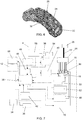
- The present invention is further explained by means of a preferred embodiment given by way of non-limiting practical example only with reference to the accompanying drawings, in which:
-
Figure 1 shows a perspective view of the device according to the invention, -
Figure 2 diagrammatically shows a detail thereof, -
Figure 3 shows a perspective view of the mechanical connection provided in the device according to the invention, in a condition in which the two portions of said connection are mutually uncoupled, -
Figure 4 shows a side view of the mechanical connection infigure 3 , -
Figure 5 shows section A-A infigure 4 , -
Figure 6 shows a perspective view of the applicator handpiece only, -
Figure 7 shows the functional connections between the components of the device in a block chart. - As shown in the figures, the improved
medical device 2 for laser therapy according to the invention comprises acontainment casing 4, which is preferably associated with asupport 6 provided withwheels 8 or other traditional means for easily moving the device itself in the work space. - Advantageously, the
containment casing 4 is made of painted PVC and anodized aluminum in order to appropriately make the device highly biocompatible. - The device also comprises a
user interface 10, which is externally associated with thecontainment casing 4 and is provided with aviewing screen 12 and a control panel provided withinput means 14, which can be operatively activated by the operator. For example, theuser interface 12 may comprise a touchscreen and/or a viewing monitor associated with a keypad/panel and/or ahandpiece 14 associated with a rotary encoder. - Two, preferably four or five,
laser sources 16 are housed inside thecontainment casing 4. - In particular, the
laser sources 16 are of the light emitting semiconductor diode (LED) type, i.e. comprise a semiconductor material, which is doped with impurities such to form a positive-negative junction (the so-called "P-N junction") so that it emits photons at a specific wavelength when it is crossed by current. - More in detail, the diodes of the
laser sources 16 are made of one or more semiconductor materials which are appropriately chosen and/or doped so that the diodes emit photons having all mutually different wavelengths, comprised in the red and infrared band, that is, substantially comprised between 550 nm and 1075 nm, and preferably comprised between about 625 nm and 1064 nm. - Furthermore, the LED diodes of the
laser sources 16 are configured so that each one emits a power substantially comprised between 500 mW and 15 W, and preferably comprised between approximately 5W and 10W. - Preferably, five LED
diode laser sources 16 are provided, each of which is configured to emit photons having different wavelength from those of the other sources. More in detail, thelaser sources 16 comprise: - a first laser source, which emits photons at about 580-680 nm, preferably at about 625 nm, with power of about 100 mW-15 W, preferably of about 5 W,
- a second laser source, which emits photons at about 750-795 nm, preferably at about 750-785 nm, with power of about 500 mW-15 W, preferably of about 5 W,
- a third laser source, which emits photons at about 800-850 nm, preferably at about 810 nm, with power of about 500 mW-15 W, preferably of about 10 W,
- a fourth laser source, which emits photons at about 915-975 nm, preferably at about 975 nm, with power of about 500 mW-15 W, preferably of about 10 W,
- a fifth laser source, which emits photons at about 1064 nm, with power of about 500 mW-15 W, preferably of about 8W.
- Preferably, the diode packages of the
laser sources 16 is of the C-mount type. Preferably, the diode package of the second, third, fourth and fifth laser source are of the C-mount type, while the diode package of the first laser source is of the TO-18 type. - Preferably, the diodes of the
laser sources 16 are made using aluminum gallium arsenide (GaAIAs), which is appropriately doped so as to emit photons with the aforesaid wavelengths, as semiconductor material. - The photons emitted by each
laser source 16 are emitted and conveyed directly into corresponding firstoptical fibers 18, also housed in thecontainment casing 4. In particular, eachlaser source 16 is associated with a firstoptical fiber 18 and, therefore, in the case of fivelaser sources 16 there are fiveoptical fibers 18, one for each of the five sources (cf.fig. 2 ). - Preferably, the central core of each first
optical fiber 18 has a diameter of about 0.12mm. Preferably, the firstoptical fibers 18 are made of silicone because they display less loss. - The
device 2 further comprises a single secondoptical fiber 22, which is positioned, at least in part, inside thecontainment casing 4 and which receives the photons which exit from all the firstoptical fibers 18. - Advantageously, the second
optical fiber 22, which is single for alllaser sources 16, is made using the liquid phase method. Preferably, the secondoptical fiber 22 is flexible with a radius of curvature greater than about 14 mm, and a cylindrical core having a diameter of about 2-10 mm, preferably of about 8 mm. -
Device 2 further comprises amechanical connection 24 to connect theoutput terminals 19 of all the first optical fibers 18 - preferably made of silicone, each of which is associated with one of thelaser sources 16 with the secondoptical fiber 22, which is preferably made using the liquid phase method and is positioned, at least in part, inside thecontainment housing 4. Preferably, themechanical connection 24 defines a removable connection between theoutput terminals 19 of all firstoptical fibers 18 and theinput end 21 of the secondoptical fiber 22 so that all the photons, which are emitted by thelaser source 16 and which have crossed the firstoptical fibers 18, enter into the secondoptical fiber 22. - In particular, each first
optical fiber 18 is inserted with an input end thereof inside the corresponding structure of thelaser source 16, while the other (output)terminal 19 is channeled, together with theoutput terminals 19 of all the other firstoptical fibers 18, inside themechanical connection 24. - Advantageously, the
mechanical connection 24 is configured so that, inside, theinput end 21 of the secondoptical fiber 22 faces and/or is aligned with theend terminals 19 of all said firstoptical fibers 18. - Advantageously, the
mechanical connection 24 is configured so that, inside, theinput end 21 of the secondoptical fiber 22 is either in contact with or in close proximity to (e.g. at a distance substantially smaller than one millimeter) theoutput terminals 19 of all said firstoptical fibers 18. - Appropriately, the diameter of the cross section of the second
optical fiber 22 is much greater than that of the firstoptical fibers 18. Preferably, the cross section area of the secondoptical fiber 22 is either substantially equal to or greater than the sum (set) of the cross section areas of all the firstoptical fibers 18. - In particular, the fact that the second
optical fiber 22 has a cross section area greater than that defined by the set of all the first optical fibers 13 combined with the use of amechanical connection 24 in which theoutput terminals 19 of all the firstoptical fibers 18 are aligned/facing and in contact with/close proximity to theinput end 21 of the single secondoptical fiber 22 avoids the use of complicated and costly collimators with particular refraction and/or focusing optics and lenses. - Advantageously, at the
input end 21 of the secondoptical fiber 22 there is a lens (not shown), which acts as diffuser for the photons which from the inneroptical fibers 18 enter into the single secondoptical fiber 22. - Advantageously, the
mechanical connection 24, which is preferably made of anodized aluminum, may be associated with thecontainment casing 4. - Preferably, the
mechanical connection 24 comprises two portions, respectively 70 and 80, which are mutually separable and couplable by joining means, preferably snap-fitting, e.g. of the male-female type. - In particular, the
male portion 70 comprises a protrudinghead 71, preferably pin-like, and atubular body 72 provided inside with a crossing and lockingseat 73 of the secondoptical fiber 22. Appropriately, the secondoptical fiber 22 is engaged inside thehead 71 so that itsinput end 21 protrudes from the head itself. Appropriately, an external covering and/or grippingsleeve 74 is also provided. - Appropriately, further seats for electrical connection wires to appropriate electrical boards housed inside the containing
casing 4 may be provided at thehead 71 of themale portion 70 of themechanical connection 24. - The
female portion 80 comprises a substantiallytubular leg 81 with acentral cavity 82, which is appropriately shaped and sized for the stable, but removable engagement and coupling of the protrudinghead 71 of themale portion 70. Advantageously, such type of connection is manually made by the user, i.e. without using any tool. - Advantageously, the
female portion 80 comprises a guiding andreference pin 83 cooperating with a correspondinghole 75 defined in themale portion 70 in order to facilitate their coupling. - All the
terminals 19 of the firstoptical fibers 18 are inserted and locked in a terminal part of thetubular leg 81 of thefemale portion 80; preferably, theterminals 19 are fixed to thetubular leg 81 by means of appropriate glue/transparent resin in order to prevent them from being pulled out. Advantageously, all theterminals 19 of the firstoptical fibers 18 may be inserted and locked in a bushing 85, which in turn is removably associated within thetubular leg 81 of thefemale portion 80. - Advantageously, the insertion of the protruding
head 71 of themale portion 70 inside thecavity 82 of thefemale portion 80 carries theinput end 21 of the single second optical fiber 22 - which is associated with the head 71 - to face and be either in contact with or in close proximity to (i.e. at a distance substantially smaller than 1 mm) theoutput terminals 19 of all firstoptical fibers 18, which are associated with thefemale portion 80. - Appropriately, said configuration of the
mechanical connection 24 which connects theoutput terminals 19 of the firstoptical fibers 18 to the input end of a single secondoptical fiber 22 has low and repeatable insertion losses, low reflected power, stability over time, reliability, is low-cost and above all avoids the use of particular refraction and focusing optics. - The second
optical fiber 22 is associated, on the other end thereof, with anapplicator handpiece 26. In particular, the latter comprises an articulatedhead 28 with asingle opening 30 communicating with the secondoptical fiber 22 to allow the release of the photons emitted by thelaser sources 16 at the tissue to be treated. Appropriately, theapplicator handpiece 16 also comprises agrip 32 to allow the operator to appropriately direct the photons output from thesingle opening 30 obtained in the handpiece itself onto the tissues of the patient to be treated. - The power of the light emissions of the
laser sources 16 detected at themechanical connection 24 is comprised in a range of about 5-60 W, preferably about 38 W, while that detected at theopening 30 of theapplicator handpiece 26, and is thus sent to the tissues to be treated, is comprised in a range of about 1-60 W, in particular is about 15 W. - Advantageously, the
device 4 comprises means for activating/deactivating thelaser sources 16 and/or for allowing/blocking the output of photons from thesingle opening 30 obtained in theapplicable handpiece 26. Preferably, these means comprise apedal switch 34 or aswitch 36 defined at thegrip 32 of thehandpiece 26. - The device also comprises a control and processing unit 38, e.g. a microprocessor and/or a CPU, which is housed in the containing
casing 4 and which manages theentire device 4, and in particular appropriately controls the laser sources 16. The control and processing unit 38 is also functionally connected to theuser interface 10. - More in detail, each
laser source 16 is associated with a current/voltage generator 40, which is activated/deactivated and/or appropriately controlled by the control and processing unit 38. - Preferably, each
laser source 16 is independently controlled, by the control and processing unit 38, so as to emit a pulse laser light beam and, in particular, for this purpose a square wave signal with frequency substantially comprised between 1 and 20000 Hz and duty cycle of at least 50% is controlled. - More in detail, on the basis of preset treatment cycles stored in the control and processing unit 38 and/or on the basis of the controls set by the operator by acting on the
user interface 10, the control and processing unit 38 singularly and independently controls the enabling/disabling of eachlaser source 16, as well as the correspondence of their optical emission power. In particular, in this fashion, the control and processing unit 38 controls the number oflaser sources 16 to be activated simultaneously and/or to be activated automatically in sequential manner. - Appropriately, the control and processing program 38 is performed by means of a connection with an external processor. As mentioned, treatment cycles are stored in the control and processing unit 38, each of which has predetermined and independent operating parameters, in terms of number of laser sources activated at the same time, emission power, activation sequence, etc.
- Appropriately, the
device 2 also comprisesmeans 42, managed by the microprocessor, to detect the current drawn by thelaser sources 16 in order to vary their corresponding efficiency state in this manner. - The power supply voltage of the
laser sources 16 for the microprocessor of the control and processing unit 38 and for the other electrical elements provided inside thedevice 2 is provided by means of aconnection 44 to the power network, which is preferably at 220V. Appropriately, anappropriate emergency control 45 is also provided so that the control and processing unit 38 may interrupt the input of the electricity from theconnection 44 to the power supply network into thedevice 2. - Advantageously, a cooling system, configured and controlled to ensure the appropriate working temperatures in the
containment casing 4, is also housed inside the containment casing itself. In particular, the cooling system comprises a heat sink with air introduction andextraction fans 46, as well as aPeltier cell 48 and atemperature sensor 50 for eachlaser source 16. - More in detail, the
temperature sensors 50 are provided to send signals corresponding to the temperature detected at eachlaser source 16 to the control and processing unit 38. Appropriately, the control and processing unit 38 is configured to control the coolingfans 46 and thecorresponding Peltier cell 48 associated with thelaser source 16 appropriately according to the basis of the received temperature signals. - Advantageously, the
device 2 also comprises an acoustic indicator 60 (e.g. a buzzer), which is controlled by the control and processing unit 38 to produce a warning when thelaser sources 16 are activated. - Advantageously, the
device 2 also comprises means 52 for detecting whether theoptical fiber 22 is correctly connected to the correspondingconnector 24 associated to thecontainment casing 4. Such means 52 appropriately comprise a traditional sensor which is mounted on a housing provided in thefemale portion 80 of theconnector 24 and which is adapted to detect the presence and/or the passage of photons in the connector itself. In particular, in case of correct insertion of themale portion 70, associated with the secondoptical fiber 22, within thefemale portion 80 of themechanical connection 24, the photons output by the firstoptical fibers 18 enter directly into the secondoptical fiber 22 and thus thesensor 52 does not detect any presence and/or anomalous passage (i.e. dispersion/loss) of photons in themechanical connection 24. -
Such sensor 52 is appropriately connected with the control and processing unit 38 so that the latter controls the automatic deactivation of thelaser sources 16 and the sending of a visual and/or acoustic warning to the operator, if the secondoptical fiber 22 is not correctly inserted in the correspondingconnector 24. - Advantageously, the
device 2 also comprises abattery 54, which is also housed in thecontainment casing 4. Preferably, thebattery 54 is managed by an appropriatelyelectronic board 56 for managing recharging and is associated with atransformer 58, preferably of lamellar type. Appropriately, thebattery 56 is activated by the control and processing unit 38 when it detects a temporary interruption of the external network power supply so as to allow, also in this case, an appropriate cooling of thelaser sources 16 housed in thechasing 4. - The device according to the invention differs with respect to traditional devices in that none of the prior art documents
US2013/0304164 ,US2007/0060984 andWO2013/052482 either describes or shows a solution provided with a plurality of first distinct optical fibers - each of which is associated with a laser source for therapeutic purposes (thus excluding those which can be used as pointers or light indicators) - which are all mechanically and removably connected to one only second optical fiber. This is particularly advantageous because it defines a particularly efficient method, which is simple to make and easy to maintain for transmitting a plurality of therapeutic light emissions to an applicator handpiece. - Furthermore, it is clearly apparent from the above that the device according to the invention is more advantageous because:
- by simultaneously emitting from two to five light emissions (photons) of different wavelengths it makes it possible to combine the anti-inflammatory, anti-edemigenous and antalgic actions (deriving mainly from photons at about 1064 nm with particularly high emission frequency, of about 10000-20000 Hz) with the cellular mitosis and myelin sheath regeneration stimulation actions (mainly deriving from the photons at 650 nm, 750 nm and 810 nm),
- it provides a single instrument which can be used to intervene on a high number of pathologies, the treatment of which by means of laser therapy is clinically validated, to the operator/therapist,
- it is suited for the application of laser therapy in dermatology, physiatry, rheumatology, pain therapy, sports medicine, etc.,
- it is safe, biocompatible, simple and easy to use for the operator,
- it makes manufacturing cost saving by virtue of its construction simplicity, and in particular of the fact that it does not have any particular collimation optics,
- it is simple to maintain because, by being mechanical and uncoupleable, the joining of the optical fibers allows the targeted replacement of the single, possibly malfunctioning optical fibers.
- Appropriately, for example, the device according to the invention is particular suited for laser therapy slipped disc treatment because it makes it possible to considerably decrease pain straight away and at the same to intervene on myelin sheath bio-stimulation.
Claims (13)
- An improved medical device (2) for laser therapy, comprising:- a containment casing (4), in which at least two laser sources are housed (16), configured to emit photons having therapeutic action, which have mutually different wavelengths and which are substantially comprised between 550 nm and 1075 nm, and with emission power substantially comprised between 500 mW and 15 W,- at least two first optical fibers (18), one for each laser source (16), which are housed in said containment casing (4) and in which the photons emitted by the corresponding laser source (16) are sent,- a single second optical fiber (22) which, at least in part, is external to said containment casing (4),- a mechanical connection (24) for connecting the output terminals (19) of all said at least two first optical fibers (18) to an input end (21) of said second optical fiber (22) so that the photons output from all said at least two first optical fibers (18) enter into said optical fiber (22),- an applicator handpiece (26), which is associated with the other end of said second optical fiber (22) and is provided with an opening (30), which communicates with said second optical fiber (22) to let out the photons emitted by said laser sources (16) at the tissue to be treated,- a control and processing unit (38) configured to control the activation/deactivation of said at least two laser sources (16) so that they emit said photons simultaneously and/or in sequence,- a user interface (10) for managing the device (2).and wherein:- said mechanical connection (24) is configured so that, in its interior, the input end (21) of the second optical fiber (22) faces and/or is aligned with the output terminals (19) of all said first optical fibers (18),- the cross-section area of the second optical fiber (22) either substantially corresponds with or is preferably greater than the sum of the cross-section areas of all the first optical fibers (18).
- A device according to claim 1, characterized in that said mechanical connection (24) removably connects the output terminals (19) of all said first optical fibers (18) with the input end (21) of the second optical fiber (22).
- A device according to one or more of the preceding claims, characterized in that said mechanical connection (24) is configured so that, inside, the input end (21) of the second optical fiber (22) is either in contact with or in close proximity to the output terminals (19) of all said first optical fibers (18).
- A device according to one or more of the preceding claims, characterized in that said mechanical connection (24) comprises two portions (70, 80), which are mutually separable and couplable by means of joining means (71, 81), the output ends (19) of said first optical fibers (18) being fixed to one (80) of said portions, while the input end (21) of said second optical fiber (22) being fixed to the other portion (70).
- A device according to one or more of the preceding claims, characterized in that said two portions (70, 80) comprise snap-fitting joining means (71, 81).
- A device according to one or more of the preceding claims, characterized in that the output terminals (19) of said first optical fibers (18) are blocked in a tubular leg (81) provided with a female cavity (82) for stably yet removably inserting a protruding male head (71) within which the input end (21) of said second optical fiber (22) is fixed.
- A device according to one or more of the preceding claims, characterized in that it comprises at least two of the following laser sources (16):- a first laser source, which emits photons at about 580-680 nm with power of about 100 mW - 15 W,- a second laser source, which emits photons at about 750-795 nm with power of about 500 mW - 15 W,- a third laser source, which emits photons at about 800-850 nm with power of about 500 mW - 15 W,- a fourth laser source, which emits photons at about 915-975 nm with power of about 500 mW - 15 W, and- a fifth laser source, which emits photons at about 1064 nm with power of about 500 mW-15 W.
- A device according to one or more of the preceding claims, characterized in that said control and processing unit (38) is configured to interdependently control each of said at least two laser sources (16) by sending a square wave signal with frequency substantially comprised between 1 and 20000 Hz and duty cycle of at least 50%.
- A device according to one or more of the preceding claims, characterized in that said at least two first optical fibers (18), which are housed in said containment casing (4) and which are each associated with a corresponding laser source (16), are made of silicone and/or in that said single second optical fiber (22), which is at least in part external to said containment casing (4), is made using the liquid phase method.
- A device according to one or more of the preceding claims, characterized in that it comprises a cooling system (46, 48, 50), which is housed inside said containment casing (4) and is configured and controlled by said control and processing unit (38) to ensure that the desired and appropriate working temperatures are present in the containment casing (4).
- A device according to one or more of the preceding claims, characterized in that it comprises means (52) for detecting whether the second optical fiber (22) is correctly inserted in said mechanical connection (24) and in that said means are functionally connected to said control and processing unit (38) to automatically control the deactivation of said at least two laser sources (16) in case of incorrect insertion of said single fiber (22) in said connection (24).
- A device according to one or more of the preceding claims, characterized in that it comprises a connection (44) with power supply of an external network and/or a battery (54) which is activated by said control and processing unit (38) when an interruption of the network power supply is detected.
- A device according to one or more of the preceding claims, characterized in that said containment casing (4) is made of biocompatible material and is associated with means (6, 8) for easily moving said device within said working space.
Applications Claiming Priority (1)
| Application Number | Priority Date | Filing Date | Title |
|---|---|---|---|
| ITUA2016A003480A ITUA20163480A1 (en) | 2016-05-16 | 2016-05-16 | Improved medical device for laser therapy. |
Publications (2)
| Publication Number | Publication Date |
|---|---|
| EP3246069A1 EP3246069A1 (en) | 2017-11-22 |
| EP3246069B1 true EP3246069B1 (en) | 2019-01-02 |
Family
ID=56894189
Family Applications (1)
| Application Number | Title | Priority Date | Filing Date |
|---|---|---|---|
| EP17171031.2A Active EP3246069B1 (en) | 2016-05-16 | 2017-05-15 | Improved medical device for laser therapy |
Country Status (2)
| Country | Link |
|---|---|
| EP (1) | EP3246069B1 (en) |
| IT (1) | ITUA20163480A1 (en) |
Families Citing this family (3)
| Publication number | Priority date | Publication date | Assignee | Title |
|---|---|---|---|---|
| US11865356B1 (en) * | 2019-04-03 | 2024-01-09 | Theralight, LLC | Light therapy device |
| KR20220112255A (en) * | 2019-11-11 | 2022-08-10 | 이엘.이엔. 에스.피.에이. | Laser device and method for skin treatment |
| WO2023126732A1 (en) * | 2021-12-27 | 2023-07-06 | Sindbad Group Limited | Method of intervertebral disc recovery in intervertebral hernia |
Family Cites Families (4)
| Publication number | Priority date | Publication date | Assignee | Title |
|---|---|---|---|---|
| US7736382B2 (en) * | 2005-09-09 | 2010-06-15 | Lockheed Martin Corporation | Apparatus for optical stimulation of nerves and other animal tissue |
| US20070239232A1 (en) * | 2006-03-28 | 2007-10-11 | Eastman Kodak Company | Light guide based light therapy device |
| WO2013052482A1 (en) * | 2011-10-03 | 2013-04-11 | University Of Rochester | Modular laser system for photodynamic therapy |
| US20130304164A1 (en) * | 2012-05-14 | 2013-11-14 | Eltech S.R.L. | Portable Apparatus for Laser Therapy |
-
2016
- 2016-05-16 IT ITUA2016A003480A patent/ITUA20163480A1/en unknown
-
2017
- 2017-05-15 EP EP17171031.2A patent/EP3246069B1/en active Active
Non-Patent Citations (1)
| Title |
|---|
| None * |
Also Published As
| Publication number | Publication date |
|---|---|
| ITUA20163480A1 (en) | 2017-11-16 |
| EP3246069A1 (en) | 2017-11-22 |
Similar Documents
| Publication | Publication Date | Title |
|---|---|---|
| US20200330184A1 (en) | Handpiece assembly for laser treatment device | |
| DK2461868T3 (en) | Handheld low-level laser therapy equipment | |
| US7695469B2 (en) | Electromagnetic energy output system | |
| US7815630B2 (en) | Target-close electromagnetic energy emitting device | |
| EP3246069B1 (en) | Improved medical device for laser therapy | |
| US20130304164A1 (en) | Portable Apparatus for Laser Therapy | |
| US20080091249A1 (en) | Photobiomodulation Apparatus with Enhanced Performance and Safety Features | |
| US20160192988A1 (en) | Multiple Laser Source System for Portable Laser Therapy Apparatus | |
| JPH0767974A (en) | Laser beam therapy | |
| US5514126A (en) | Fiber optic assembly for laser treatment system | |
| JP6106375B2 (en) | Phototherapy device | |
| US20170225011A1 (en) | Laser device for intracranial illumination via oral or nasal foramina access | |
| JP2014526922A (en) | Hand-held laser device featuring a sensor for eye-safe start-up | |
| EP2126466B1 (en) | Target-close electromagnetic energy emitting device | |
| KR101471884B1 (en) | Portable handpiece treatment apparatus using laser | |
| US20200360547A1 (en) | Modular wound disinfection system and method using non-ionizing electromagnetic radiation | |
| US20190254744A1 (en) | Handpiece Apparatus, System, and Method for Laser Treatment | |
| US20170035506A1 (en) | Laser Diode Package Arrangement with Interchangable Tip | |
| KR20200102623A (en) | Medical Laser Irradiation Apparatus | |
| CA3037995C (en) | System for surgical treatment | |
| EP3148468B1 (en) | Apparatus for stimulation and/or treatment of anatomical tissues | |
| CN114466678A (en) | System for combining therapeutic laser and curing light | |
| KR20200080874A (en) | Laser acupuncture | |
| KR20100120821A (en) | Portable phototherapy device for skin care |
Legal Events
| Date | Code | Title | Description |
|---|---|---|---|
| PUAI | Public reference made under article 153(3) epc to a published international application that has entered the european phase |
Free format text: ORIGINAL CODE: 0009012 |
|
| STAA | Information on the status of an ep patent application or granted ep patent |
Free format text: STATUS: THE APPLICATION HAS BEEN PUBLISHED |
|
| AK | Designated contracting states |
Kind code of ref document: A1 Designated state(s): AL AT BE BG CH CY CZ DE DK EE ES FI FR GB GR HR HU IE IS IT LI LT LU LV MC MK MT NL NO PL PT RO RS SE SI SK SM TR |
|
| AX | Request for extension of the european patent |
Extension state: BA ME |
|
| STAA | Information on the status of an ep patent application or granted ep patent |
Free format text: STATUS: REQUEST FOR EXAMINATION WAS MADE |
|
| 17P | Request for examination filed |
Effective date: 20180515 |
|
| RBV | Designated contracting states (corrected) |
Designated state(s): AL AT BE BG CH CY CZ DE DK EE ES FI FR GB GR HR HU IE IS IT LI LT LU LV MC MK MT NL NO PL PT RO RS SE SI SK SM TR |
|
| GRAP | Despatch of communication of intention to grant a patent |
Free format text: ORIGINAL CODE: EPIDOSNIGR1 |
|
| STAA | Information on the status of an ep patent application or granted ep patent |
Free format text: STATUS: GRANT OF PATENT IS INTENDED |
|
| RIC1 | Information provided on ipc code assigned before grant |
Ipc: A61N 5/06 20060101AFI20180705BHEP |
|
| INTG | Intention to grant announced |
Effective date: 20180802 |
|
| GRAS | Grant fee paid |
Free format text: ORIGINAL CODE: EPIDOSNIGR3 |
|
| GRAA | (expected) grant |
Free format text: ORIGINAL CODE: 0009210 |
|
| STAA | Information on the status of an ep patent application or granted ep patent |
Free format text: STATUS: THE PATENT HAS BEEN GRANTED |
|
| AK | Designated contracting states |
Kind code of ref document: B1 Designated state(s): AL AT BE BG CH CY CZ DE DK EE ES FI FR GB GR HR HU IE IS IT LI LT LU LV MC MK MT NL NO PL PT RO RS SE SI SK SM TR |
|
| REG | Reference to a national code |
Ref country code: GB Ref legal event code: FG4D |
|
| REG | Reference to a national code |
Ref country code: CH Ref legal event code: EP Ref country code: AT Ref legal event code: REF Ref document number: 1083624 Country of ref document: AT Kind code of ref document: T Effective date: 20190115 |
|
| REG | Reference to a national code |
Ref country code: IE Ref legal event code: FG4D |
|
| REG | Reference to a national code |
Ref country code: DE Ref legal event code: R096 Ref document number: 602017001649 Country of ref document: DE |
|
| REG | Reference to a national code |
Ref country code: NL Ref legal event code: MP Effective date: 20190102 |
|
| REG | Reference to a national code |
Ref country code: LT Ref legal event code: MG4D |
|
| REG | Reference to a national code |
Ref country code: AT Ref legal event code: MK05 Ref document number: 1083624 Country of ref document: AT Kind code of ref document: T Effective date: 20190102 |
|
| PG25 | Lapsed in a contracting state [announced via postgrant information from national office to epo] |
Ref country code: NL Free format text: LAPSE BECAUSE OF FAILURE TO SUBMIT A TRANSLATION OF THE DESCRIPTION OR TO PAY THE FEE WITHIN THE PRESCRIBED TIME-LIMIT Effective date: 20190102 |
|
| PG25 | Lapsed in a contracting state [announced via postgrant information from national office to epo] |
Ref country code: PT Free format text: LAPSE BECAUSE OF FAILURE TO SUBMIT A TRANSLATION OF THE DESCRIPTION OR TO PAY THE FEE WITHIN THE PRESCRIBED TIME-LIMIT Effective date: 20190502 Ref country code: ES Free format text: LAPSE BECAUSE OF FAILURE TO SUBMIT A TRANSLATION OF THE DESCRIPTION OR TO PAY THE FEE WITHIN THE PRESCRIBED TIME-LIMIT Effective date: 20190102 Ref country code: SE Free format text: LAPSE BECAUSE OF FAILURE TO SUBMIT A TRANSLATION OF THE DESCRIPTION OR TO PAY THE FEE WITHIN THE PRESCRIBED TIME-LIMIT Effective date: 20190102 Ref country code: FI Free format text: LAPSE BECAUSE OF FAILURE TO SUBMIT A TRANSLATION OF THE DESCRIPTION OR TO PAY THE FEE WITHIN THE PRESCRIBED TIME-LIMIT Effective date: 20190102 Ref country code: NO Free format text: LAPSE BECAUSE OF FAILURE TO SUBMIT A TRANSLATION OF THE DESCRIPTION OR TO PAY THE FEE WITHIN THE PRESCRIBED TIME-LIMIT Effective date: 20190402 Ref country code: LT Free format text: LAPSE BECAUSE OF FAILURE TO SUBMIT A TRANSLATION OF THE DESCRIPTION OR TO PAY THE FEE WITHIN THE PRESCRIBED TIME-LIMIT Effective date: 20190102 Ref country code: PL Free format text: LAPSE BECAUSE OF FAILURE TO SUBMIT A TRANSLATION OF THE DESCRIPTION OR TO PAY THE FEE WITHIN THE PRESCRIBED TIME-LIMIT Effective date: 20190102 |
|
| PG25 | Lapsed in a contracting state [announced via postgrant information from national office to epo] |
Ref country code: BG Free format text: LAPSE BECAUSE OF FAILURE TO SUBMIT A TRANSLATION OF THE DESCRIPTION OR TO PAY THE FEE WITHIN THE PRESCRIBED TIME-LIMIT Effective date: 20190402 Ref country code: IS Free format text: LAPSE BECAUSE OF FAILURE TO SUBMIT A TRANSLATION OF THE DESCRIPTION OR TO PAY THE FEE WITHIN THE PRESCRIBED TIME-LIMIT Effective date: 20190502 Ref country code: GR Free format text: LAPSE BECAUSE OF FAILURE TO SUBMIT A TRANSLATION OF THE DESCRIPTION OR TO PAY THE FEE WITHIN THE PRESCRIBED TIME-LIMIT Effective date: 20190403 Ref country code: HR Free format text: LAPSE BECAUSE OF FAILURE TO SUBMIT A TRANSLATION OF THE DESCRIPTION OR TO PAY THE FEE WITHIN THE PRESCRIBED TIME-LIMIT Effective date: 20190102 Ref country code: LV Free format text: LAPSE BECAUSE OF FAILURE TO SUBMIT A TRANSLATION OF THE DESCRIPTION OR TO PAY THE FEE WITHIN THE PRESCRIBED TIME-LIMIT Effective date: 20190102 Ref country code: RS Free format text: LAPSE BECAUSE OF FAILURE TO SUBMIT A TRANSLATION OF THE DESCRIPTION OR TO PAY THE FEE WITHIN THE PRESCRIBED TIME-LIMIT Effective date: 20190102 |
|
| REG | Reference to a national code |
Ref country code: DE Ref legal event code: R097 Ref document number: 602017001649 Country of ref document: DE |
|
| PG25 | Lapsed in a contracting state [announced via postgrant information from national office to epo] |
Ref country code: CZ Free format text: LAPSE BECAUSE OF FAILURE TO SUBMIT A TRANSLATION OF THE DESCRIPTION OR TO PAY THE FEE WITHIN THE PRESCRIBED TIME-LIMIT Effective date: 20190102 Ref country code: RO Free format text: LAPSE BECAUSE OF FAILURE TO SUBMIT A TRANSLATION OF THE DESCRIPTION OR TO PAY THE FEE WITHIN THE PRESCRIBED TIME-LIMIT Effective date: 20190102 Ref country code: DK Free format text: LAPSE BECAUSE OF FAILURE TO SUBMIT A TRANSLATION OF THE DESCRIPTION OR TO PAY THE FEE WITHIN THE PRESCRIBED TIME-LIMIT Effective date: 20190102 Ref country code: EE Free format text: LAPSE BECAUSE OF FAILURE TO SUBMIT A TRANSLATION OF THE DESCRIPTION OR TO PAY THE FEE WITHIN THE PRESCRIBED TIME-LIMIT Effective date: 20190102 Ref country code: AT Free format text: LAPSE BECAUSE OF FAILURE TO SUBMIT A TRANSLATION OF THE DESCRIPTION OR TO PAY THE FEE WITHIN THE PRESCRIBED TIME-LIMIT Effective date: 20190102 Ref country code: AL Free format text: LAPSE BECAUSE OF FAILURE TO SUBMIT A TRANSLATION OF THE DESCRIPTION OR TO PAY THE FEE WITHIN THE PRESCRIBED TIME-LIMIT Effective date: 20190102 Ref country code: SK Free format text: LAPSE BECAUSE OF FAILURE TO SUBMIT A TRANSLATION OF THE DESCRIPTION OR TO PAY THE FEE WITHIN THE PRESCRIBED TIME-LIMIT Effective date: 20190102 |
|
| PGFP | Annual fee paid to national office [announced via postgrant information from national office to epo] |
Ref country code: IE Payment date: 20190724 Year of fee payment: 3 |
|
| PLBE | No opposition filed within time limit |
Free format text: ORIGINAL CODE: 0009261 |
|
| STAA | Information on the status of an ep patent application or granted ep patent |
Free format text: STATUS: NO OPPOSITION FILED WITHIN TIME LIMIT |
|
| PG25 | Lapsed in a contracting state [announced via postgrant information from national office to epo] |
Ref country code: SM Free format text: LAPSE BECAUSE OF FAILURE TO SUBMIT A TRANSLATION OF THE DESCRIPTION OR TO PAY THE FEE WITHIN THE PRESCRIBED TIME-LIMIT Effective date: 20190102 |
|
| 26N | No opposition filed |
Effective date: 20191003 |
|
| PG25 | Lapsed in a contracting state [announced via postgrant information from national office to epo] |
Ref country code: MC Free format text: LAPSE BECAUSE OF FAILURE TO SUBMIT A TRANSLATION OF THE DESCRIPTION OR TO PAY THE FEE WITHIN THE PRESCRIBED TIME-LIMIT Effective date: 20190102 |
|
| REG | Reference to a national code |
Ref country code: BE Ref legal event code: MM Effective date: 20190531 |
|
| PG25 | Lapsed in a contracting state [announced via postgrant information from national office to epo] |
Ref country code: SI Free format text: LAPSE BECAUSE OF FAILURE TO SUBMIT A TRANSLATION OF THE DESCRIPTION OR TO PAY THE FEE WITHIN THE PRESCRIBED TIME-LIMIT Effective date: 20190102 Ref country code: LU Free format text: LAPSE BECAUSE OF NON-PAYMENT OF DUE FEES Effective date: 20190515 |
|
| PG25 | Lapsed in a contracting state [announced via postgrant information from national office to epo] |
Ref country code: TR Free format text: LAPSE BECAUSE OF FAILURE TO SUBMIT A TRANSLATION OF THE DESCRIPTION OR TO PAY THE FEE WITHIN THE PRESCRIBED TIME-LIMIT Effective date: 20190102 |
|
| PG25 | Lapsed in a contracting state [announced via postgrant information from national office to epo] |
Ref country code: BE Free format text: LAPSE BECAUSE OF NON-PAYMENT OF DUE FEES Effective date: 20190531 |
|
| PG25 | Lapsed in a contracting state [announced via postgrant information from national office to epo] |
Ref country code: FR Free format text: LAPSE BECAUSE OF NON-PAYMENT OF DUE FEES Effective date: 20190531 |
|
| PG25 | Lapsed in a contracting state [announced via postgrant information from national office to epo] |
Ref country code: CH Free format text: LAPSE BECAUSE OF NON-PAYMENT OF DUE FEES Effective date: 20200531 Ref country code: LI Free format text: LAPSE BECAUSE OF NON-PAYMENT OF DUE FEES Effective date: 20200531 |
|
| PG25 | Lapsed in a contracting state [announced via postgrant information from national office to epo] |
Ref country code: IE Free format text: LAPSE BECAUSE OF NON-PAYMENT OF DUE FEES Effective date: 20200515 |
|
| PG25 | Lapsed in a contracting state [announced via postgrant information from national office to epo] |
Ref country code: CY Free format text: LAPSE BECAUSE OF FAILURE TO SUBMIT A TRANSLATION OF THE DESCRIPTION OR TO PAY THE FEE WITHIN THE PRESCRIBED TIME-LIMIT Effective date: 20190102 |
|
| PG25 | Lapsed in a contracting state [announced via postgrant information from national office to epo] |
Ref country code: HU Free format text: LAPSE BECAUSE OF FAILURE TO SUBMIT A TRANSLATION OF THE DESCRIPTION OR TO PAY THE FEE WITHIN THE PRESCRIBED TIME-LIMIT; INVALID AB INITIO Effective date: 20170515 Ref country code: MT Free format text: LAPSE BECAUSE OF FAILURE TO SUBMIT A TRANSLATION OF THE DESCRIPTION OR TO PAY THE FEE WITHIN THE PRESCRIBED TIME-LIMIT Effective date: 20190102 |
|
| GBPC | Gb: european patent ceased through non-payment of renewal fee |
Effective date: 20210515 |
|
| PG25 | Lapsed in a contracting state [announced via postgrant information from national office to epo] |
Ref country code: GB Free format text: LAPSE BECAUSE OF NON-PAYMENT OF DUE FEES Effective date: 20210515 |
|
| PG25 | Lapsed in a contracting state [announced via postgrant information from national office to epo] |
Ref country code: MK Free format text: LAPSE BECAUSE OF FAILURE TO SUBMIT A TRANSLATION OF THE DESCRIPTION OR TO PAY THE FEE WITHIN THE PRESCRIBED TIME-LIMIT Effective date: 20190102 |
|
| PGFP | Annual fee paid to national office [announced via postgrant information from national office to epo] |
Ref country code: IT Payment date: 20230511 Year of fee payment: 7 Ref country code: DE Payment date: 20230516 Year of fee payment: 7 |