EP3245933B1 - Apparatus and method of providing an interface to an electrically powered instrument - Google Patents
Apparatus and method of providing an interface to an electrically powered instrument Download PDFInfo
- Publication number
- EP3245933B1 EP3245933B1 EP17172108.7A EP17172108A EP3245933B1 EP 3245933 B1 EP3245933 B1 EP 3245933B1 EP 17172108 A EP17172108 A EP 17172108A EP 3245933 B1 EP3245933 B1 EP 3245933B1
- Authority
- EP
- European Patent Office
- Prior art keywords
- connector
- power transfer
- optical
- transfer element
- operating position
- Prior art date
- Legal status (The legal status is an assumption and is not a legal conclusion. Google has not performed a legal analysis and makes no representation as to the accuracy of the status listed.)
- Active
Links
Images




Classifications
-
- A—HUMAN NECESSITIES
- A61—MEDICAL OR VETERINARY SCIENCE; HYGIENE
- A61B—DIAGNOSIS; SURGERY; IDENTIFICATION
- A61B1/00—Instruments for performing medical examinations of the interior of cavities or tubes of the body by visual or photographical inspection, e.g. endoscopes; Illuminating arrangements therefor
- A61B1/00002—Operational features of endoscopes
- A61B1/00011—Operational features of endoscopes characterised by signal transmission
- A61B1/00013—Operational features of endoscopes characterised by signal transmission using optical means
-
- A—HUMAN NECESSITIES
- A61—MEDICAL OR VETERINARY SCIENCE; HYGIENE
- A61B—DIAGNOSIS; SURGERY; IDENTIFICATION
- A61B1/00—Instruments for performing medical examinations of the interior of cavities or tubes of the body by visual or photographical inspection, e.g. endoscopes; Illuminating arrangements therefor
- A61B1/00002—Operational features of endoscopes
- A61B1/00025—Operational features of endoscopes characterised by power management
- A61B1/00027—Operational features of endoscopes characterised by power management characterised by power supply
- A61B1/00029—Operational features of endoscopes characterised by power management characterised by power supply externally powered, e.g. wireless
-
- A—HUMAN NECESSITIES
- A61—MEDICAL OR VETERINARY SCIENCE; HYGIENE
- A61B—DIAGNOSIS; SURGERY; IDENTIFICATION
- A61B1/00—Instruments for performing medical examinations of the interior of cavities or tubes of the body by visual or photographical inspection, e.g. endoscopes; Illuminating arrangements therefor
- A61B1/00112—Connection or coupling means
- A61B1/00121—Connectors, fasteners and adapters, e.g. on the endoscope handle
- A61B1/00124—Connectors, fasteners and adapters, e.g. on the endoscope handle electrical, e.g. electrical plug-and-socket connection
-
- A—HUMAN NECESSITIES
- A61—MEDICAL OR VETERINARY SCIENCE; HYGIENE
- A61B—DIAGNOSIS; SURGERY; IDENTIFICATION
- A61B1/00—Instruments for performing medical examinations of the interior of cavities or tubes of the body by visual or photographical inspection, e.g. endoscopes; Illuminating arrangements therefor
- A61B1/00112—Connection or coupling means
- A61B1/00121—Connectors, fasteners and adapters, e.g. on the endoscope handle
- A61B1/00126—Connectors, fasteners and adapters, e.g. on the endoscope handle optical, e.g. for light supply cables
-
- G—PHYSICS
- G02—OPTICS
- G02B—OPTICAL ELEMENTS, SYSTEMS OR APPARATUS
- G02B6/00—Light guides; Structural details of arrangements comprising light guides and other optical elements, e.g. couplings
-
- G—PHYSICS
- G02—OPTICS
- G02B—OPTICAL ELEMENTS, SYSTEMS OR APPARATUS
- G02B6/00—Light guides; Structural details of arrangements comprising light guides and other optical elements, e.g. couplings
- G02B6/24—Coupling light guides
- G02B6/36—Mechanical coupling means
- G02B6/40—Mechanical coupling means having fibre bundle mating means
- G02B6/406—Mechanical coupling means having fibre bundle mating means of the ferrule type, connecting a plurality of pairs of ferrules
-
- G—PHYSICS
- G02—OPTICS
- G02B—OPTICAL ELEMENTS, SYSTEMS OR APPARATUS
- G02B6/00—Light guides; Structural details of arrangements comprising light guides and other optical elements, e.g. couplings
- G02B6/24—Coupling light guides
- G02B6/42—Coupling light guides with opto-electronic elements
- G02B6/4201—Packages, e.g. shape, construction, internal or external details
- G02B6/4204—Packages, e.g. shape, construction, internal or external details the coupling comprising intermediate optical elements, e.g. lenses, holograms
-
- G—PHYSICS
- G02—OPTICS
- G02B—OPTICAL ELEMENTS, SYSTEMS OR APPARATUS
- G02B6/00—Light guides; Structural details of arrangements comprising light guides and other optical elements, e.g. couplings
- G02B6/24—Coupling light guides
- G02B6/42—Coupling light guides with opto-electronic elements
- G02B6/4201—Packages, e.g. shape, construction, internal or external details
- G02B6/4274—Electrical aspects
- G02B6/4278—Electrical aspects related to pluggable or demountable opto-electronic or electronic elements
-
- G—PHYSICS
- G02—OPTICS
- G02B—OPTICAL ELEMENTS, SYSTEMS OR APPARATUS
- G02B6/00—Light guides; Structural details of arrangements comprising light guides and other optical elements, e.g. couplings
- G02B6/24—Coupling light guides
- G02B6/42—Coupling light guides with opto-electronic elements
- G02B6/4292—Coupling light guides with opto-electronic elements the light guide being disconnectable from the opto-electronic element, e.g. mutually self aligning arrangements
- G02B6/4293—Coupling light guides with opto-electronic elements the light guide being disconnectable from the opto-electronic element, e.g. mutually self aligning arrangements hybrid electrical and optical connections for transmitting electrical and optical signals
-
- G—PHYSICS
- G02—OPTICS
- G02B—OPTICAL ELEMENTS, SYSTEMS OR APPARATUS
- G02B6/00—Light guides; Structural details of arrangements comprising light guides and other optical elements, e.g. couplings
- G02B6/44—Mechanical structures for providing tensile strength and external protection for fibres, e.g. optical transmission cables
- G02B6/4401—Optical cables
- G02B6/441—Optical cables built up from sub-bundles
-
- G—PHYSICS
- G02—OPTICS
- G02B—OPTICAL ELEMENTS, SYSTEMS OR APPARATUS
- G02B6/00—Light guides; Structural details of arrangements comprising light guides and other optical elements, e.g. couplings
- G02B6/44—Mechanical structures for providing tensile strength and external protection for fibres, e.g. optical transmission cables
- G02B6/4401—Optical cables
- G02B6/4415—Cables for special applications
- G02B6/4416—Heterogeneous cables
Definitions
- the invention relates to electrical power and data interfaces with observation instruments, including optical instruments such as endoscopic devices. More particularly, the invention relates to connectors which are used to provide an interface between an electrically operated instrument and control or related equipment for the instrument. The invention also relates to methods for providing such an interface.
- Observation instruments including optical instruments such as endoscopes, borescopes, and exoscopes may include an electronic imaging device located, for example, at the distal end of an elongated shaft or in a camera head which is connected to an elongated shaft. Whether positioned at the distal end of the endoscope shaft or in the camera head, the electronic imaging device may be one or more charge coupled devices (CCDs) or CMOS imaging devices together with other electronic components. Other electronic devices such as LED or other light sources may be included in the instrument.
- CCDs charge coupled devices
- CMOS imaging devices CMOS imaging devices
- the camera head (or an instrument body or handle in the case of some observation instruments) is typically connected via a suitable cable to a camera control unit, commonly referred to as a "CCU.”
- the cable provides paths for carrying electrical power to the camera head and data signals to and from the camera head.
- image data captured by the imaging device is transmitted over the cable to the CCU for processing and ultimately for display on monitors which are connected directly to the CCU or to an intermediate monitor driving device.
- Control signals and power for operating the electronic components in the instrument may be transmitted over the cable from the CCU to the scope and/or camera head.
- US 2015/0250378 A1 uses a cable between a camera head and CCU which includes optical fibers for carrying optical data signals from the camera head to the CCU.
- the camera head in this example includes circuitry for converting the captured image data from the electronic data signals generated by the imaging device to optical data signals which are then inserted into the optical fibers of the cable.
- US 2015/0250378 A1 also discloses that the cable from the camera head to CCU may include electrical signal paths in addition to the optical signal paths.
- US 2008/0225134 A1 shows another endoscopic system having a cable between the CCU and camera head which includes both electrical signal paths and an optical path.
- the optical path is used to provide illumination light to the endoscope.
- an intrapersonal data communication system is described (title; column 1, lines 30 through 32; column 6, lines 14 through 17; etc.).
- the system comprises an optical digital signal adapter 401 or a signal converter 400 within a local device and an optical digital signal link 402 (column 25, lines 7 through 51; Figures 4A, 4B, 4C ).
- the optical signal link 402 comprises electrical lines (no reference numeral), optical fibers 418 and non-contact optical connectors 422, 423 (Column 25, lines 52 and 57; Figures 4A, 4B, 4C ).
- optical signal adapter 401 or the signal converter 400 At an interface between the optical signal adapter 401 or the signal converter 400 and the optical digital signal link 402, electrical power is transferred via connector elements 424, 425 (column 25, lines 52 through 54; Figures 4A, 4B, 4C ), and optical digital signals pass through collimating lenses 420, 427 and focusing lenses 426, 421 and transparent windows 428, 429 at both sides of the interface (column 27, lines 3 through 37; Figure 4A, 4B, 4C ).
- An endoscope 21 includes a body unit 22 held by an endoscope holding section 20 (paragraph [0026]; Figure 1 ).
- the body unit 22 comprises an insertion-section-side body 50 as a first member and a power unit 51 as a second member (paragraph [0034]; Figure 2 ).
- the power unit 51 is provided with a chassis 85 having a cavity portion 86 (paragraph [0058]; Figure 4 ).
- a first wiper 101 provided in the cavity portion 86 removes moisture disposed adjacent electrical terminal portions 97 at the insertion-section body 50 (paragraph [0065]; Figure 4 ) and a light guide 46 in the insertion portion 50 guiding illumination light (paragraphs [0036], [0037]; Figure 4 ) and a light guide 115 in the power unit 51 (paragraph [0035]; Figure 4 ) are optically coupled (paragraph [0076]; Figure 4 ).
- a cable assembly 100 comprising an optical connector assembly 101 employing a translating element 110 is described (paragraph [0039]; Figure 1 ).
- the optical translating element 110 comprises a coupling surface 126 and lenses 122 exposed at the coupling surface 126 (paragraph [0042]; Figure 1 ).
- the optical connector assembly 101 comprises electrical contacts 141a, 141b configured to pass electrical power and/or data (paragraph [0046]; Figure 1 ).
- an endoscope system 10 for wirelessly transmitting energy and data is described (paragraph [0051]; Figure 1 ).
- a transponder/transceiver 20 is mounted and communicates with a camera head transponder/transceiver 24 mounted on a detachable camera head 14 (paragraph [0051]; Figure 1 ).
- An endoscope 290 houses a wire coil 320, another wire coil 370 is positioned in a camera head 360 (paragraph [0082]; Figure 4 ). Power is supplied to the camera head coil 370 through a camera cable 390 and wirelessly transmitted across the camera-endoscope interface to the endoscope wire coil 320 inductively (paragraph [0082]; Figure 4 ).
- the endoscope can rotate freely in a coupling mechanism 350 at the camera head 360 (paragraph [0082]).
- an electronic endoscope apparatus 1 comprising an electronic endoscope 2 and a processor device 3 is described (paragraphs [0005], [0014], [0028], figure 1 ).
- a connector 13 at the end of a universal cord 12 of the electronic endoscope 2 can be connected to a connector 14 of the processor device 3 (paragraph [0029], figure 1 ).
- the universal cord 12 includes a wiring group 30 transmitting operating power and control signals and image signals (paragraph [0034], figure 2 ).
- the connector 13 of the electronic endoscope 2 comprises an input/output unit 31, and the connector 14 of the processor device 3 comprises an input/output unit 33 (paragraphs [0036], [0037], figure 2 ).
- a light-emitting element 41 a is provided on a signal output side of each of the input/output units 31, 33, and a light-receiving element 41b is provided on an input side of each of the input/output units 31, 33 (paragraph [0042], figure 2 ).
- the light-emitting elements 41 a and the light-receiving elements 41b transmit signals by using light (paragraph [0042], figure 2 ).
- a contact part 32 of the connector 13 of the endoscope 2 is connected to ground of the electronic endoscope 2 (paragraph [0036], figure 2 ).
- a contact part 34 of the connector 14 of the processor device 3 is connected to a housing 36 of the grounded processor device 3 through a capacitor C1 (paragraph [0038], figure 2 ).
- the contact parts 32, 34 of the connectors 13, 14 come into contact with each other, so that ground of the electronic endoscope 2 and the housing 36 of the processor device 3 are electrically connected to each other (paragraph [0044]). Thereby, in influence of noises on the electronic endoscope 2 is reduced (paragraph [0045]).
- An endoscopic imaging system 10 comprises a camera head 12 and a camera control unit 14, wherein the camera head 12 may be used together with an endoscope (paragraph [0028], figure 1 ). Data are transmitted via extremely high frequency (e.g. 60 GHz) radio communication (paragraph [0038]). Power is inductively transferred from a transmitter coil 158 in a body 114 of a camera control unit connector 102 of the camera control unit 14 to a receiver coil 154 related to the camera head 12 (paragraphs [0034], [0035], [0042]). An electromagnetic spring clip 126 is mounted between a capacitor 124 and a shield box 116, engages an exposed metal shield 106 of a camera head connector 100 and controls undesired electromagnetic emission and protects the camera system from electromagnetic interference (paragraph [0035]).
- an endoscope system 1 comprising a flexible endoscope 3A and an endoscope system controlling device 5 performing signal processing for an image pickup device built into the endoscope 3A is described (paragraph [0018], figure 1 ).
- a "general connector portion" 52 of a "tube unit” 19 (cf. paragraph [0024]; in figures 1 , 2 : like a cable) is coupled to a "connector portion" 51 of the "endoscope main unit” 18 (paragraph [0072], figure 2 ).
- the connector portion 51 of the endoscope main unit 18 and the general connector portion 52 of the "tube unit” 19 comprise coils forming contactless transmitting sections 72a, 72b (paragraph [0072], [0074], [0076]). Power and signals are transmitted via the contactless transmitting sections 72a, 72b (paragraphs [0075], [0077]).
- Medical devices such as endoscopes require an electrical isolation barrier between the CCU and camera head/endoscope.
- This electrical isolation barrier is required to ensure that an inappropriate electrical signal is not inadvertently applied to the endoscope and thus to the patient in which the endoscope is used.
- a cable running between the CCU and endoscope includes electrical signal paths, such as in both of the above-mentioned U.S. patent application publications, it has been necessary for the electrical isolation barrier to be included in the circuitry of the CCU. This requirement of the electrical isolation barrier in the CCU greatly complicates the circuitry of the device.
- An interface device includes a first connector and a second connector adapted to be joined together in an operating position.
- One or more first optical data conduits such as optical fibers extend through the first connector, with each first optical data conduit terminating at a respective first optical conduit end which is operatively aligned with a respective first optical lens.
- One or more second optical data conduits (which may similarly comprise optical fibers) extend through the second connector, with each second optical data conduit terminating at a respective second optical conduit end which is operatively aligned with a respective second optical lens.
- optical coupling in the present disclosure and accompanying claims means an arrangement in which light exiting a fiber end passes through the corresponding optical lenses and is directed into the end of the corresponding optical fiber.
- the interface also includes an electrical power transfer arrangement.
- This arrangement includes a first electrical power transfer element mounted on the first connector and a second electrical power transfer element mounted on the second connector. These electrical power transfer elements are located in a power transfer orientation with respect to each other when the first connector and second connector are joined in the operating position, and this facilitates the transfer of electrical power from one of the connectors to the other.
- the expanded beam optical data communication arrangement together with the electrical power transfer arrangement has the advantage that very high data transfer rates are possible across the interface, while electrical power for electronic components may also be transferred across the interface. High data transfer rates are particularly advantageous where the interface is used in medical instrument systems such as video endoscope systems in which a high-resolution image is captured with electronic components at the instrument, and then the voluminous image data is transferred to a control system for processing.
- the expanded beam optical communication arrangement accommodates the high data rates which may be required while the power transfer arrangement accommodates the transfer of electrical power to the imaging and optical signal generation elements required for image collection and optical data communication.
- the electrical power transfer elements may be configured so that the electrical power is transferred inductively across the elements.
- all electrical circuits associated with the first connector may be electrically isolated from all electrical circuits associated with the second connector.
- the interface forms an electrical isolation barrier.
- the interface may be placed at any one of a number of alternative locations in a medical device system such as an endoscopic system to eliminate the need for a complicated electrical isolation barrier in the system control equipment.
- a connector according to this second aspect of the invention includes a connector body and an optical data conduit extending through the connector body and terminating at a conduit end within the connector body.
- An optical lens is included in the connector body and is operatively aligned with the conduit end.
- An electrical power transfer element is also mounted within the connector body.
- a connector according to either of the above aspects of the present invention may include a cable connected to the connector body.
- the cable may include continuations of the optical data conduits of the connector and also electrical conductors for carrying the desired electrical power signal to or from the connector.
- electrical isolation is provided across a connection made by the connectors, all electrical circuits included in the connector are electrically isolated within the connector body aside from electrical continuity to the power conductor arrangement within the cable.
- Another aspect of the invention includes a method of providing an interface between an electrically powered instrument and a control system for the instrument.
- a method according to this additional aspect of the invention includes placing a first connector in an operating position with respect to a second connector and directing optical data along an optical path defined through the first and second connectors in the operating position. This optical path includes a first optical conduit extending through the first connector, second optical conduit extending through the second connector, and a coupling region interposed between the first optical conduit and the second optical conduit.
- a method according to this additional aspect of the invention further includes expanding an area of an optical signal (the signal carrying the optical data) at a first side of the coupling region and reducing the area of the optical signal at a second side of the coupling region. Additionally, electrical power is transferred from a first power transfer element included with the first connector to a second power transfer element included with the second connector.
- the first connector defines a receptacle.
- the connector defining the receptacle may advantageously be contained within a housing for a camera control unit of the endoscopic system.
- the interface may employ an inductive coupling between the power transfer elements in order to maintain electrical isolation between the two complementary connectors.
- Any suitable inductive coupling arrangement may be employed according to the invention.
- the first electrical power transfer element comprises a first planar spiral coil and the second electrical power transfer element comprises a second planar spiral coil.
- the first planar spiral coil may be aligned parallel to a first side of the first connector and the second planar spiral coil may be aligned parallel to a first side of the second connector.
- the two planar spiral coils align with each other sufficiently when the connectors are in the operating position to provide inductive coupling between the coils.
- the electrical power transfer elements may comprise helical coils.
- the first electrical power transfer element may comprise a first helical coil and the second electrical power transfer element may comprise a second helical coil adapted to align with the first helical coil and reside within an area defined by the first helical coil when the first connector and the second connector are joined in the operating position.
- a suitable transparent protective material may be mounted on the respective connector to protect the optical lens or lenses.
- the transparent protective layer may be mounted on the respective connector in position to reside between each optical lens of that connector and the opposite connector when the connectors are in the operating position.
- the electrically powered instrument may be an observation instrument.
- an observation instrument might be an optical instrument such as a video camera, endoscope, exoscope, or borescope.
- Embodiments also include apparatus and methods for other electrically powered instruments.
- optical instruments e.g., video cameras, endoscopes, exoscopes, borescopes
- high-resolution imaging e.g., a 4K resolution design
- an interface or connector within the scope of the following claims may have application in connection with any observation instrument.
- FIG. 1 shows an endoscopic system 100 employing an interface device 101 according to the present invention.
- System 100 includes a camera control unit (“CCU") 104, a camera head 105, and an endoscope 106.
- CCU 104 is connected to send a signal to a monitor control unit 108 connected to monitors 109 for displaying images from camera head 105 or endoscope 106.
- Interface device 101 is interposed between CCU 104 and camera head 105 and functions as a detachable link for data communication and power transfer between the CCU and camera head. Both the data communication and power transfer functions are preferably provided across interface device 101 while the device also maintains an electrical isolation barrier to camera head 105 and endoscope 106. Data is communicated in the form of optical data signals S in FIG. 1 , both from camera head 105 and/or endoscope 106 to CCU 104 and also preferably in the opposite direction from the CCU to the camera head and/or endoscope. Electrical power (P in FIG. 1 ) is transferred only in the direction from CCU 104 to camera head 105 and/or endoscope 106.
- the data transmission rates possible via optical data transmission in the direction from the camera head 105 to CCU 104 is particularly advantageous for transmitting the large amounts of image data that may be collected by an imaging device or multiple imaging devices (not shown) associated with endoscope 106 or camera head 105.
- Data which may be transmitted from CCU 104 to camera head 105 and/or endoscope 106 may comprise control instructions and operational instructions and data, which may typically be of lesser volume as compared to the image data transmitted in the opposite direction.
- Interface device 101 includes a first connector 111 and a second connector 112 which may be connected in an operating position to facilitate the desired data communication and power transfer.
- This operating position is schematically indicated in FIG. 1 and will be described in further detail below with reference particularly to FIGS. 2 and 9 .
- the two connectors 111 and 112 may be readily separated to detach camera head 105 and endoscope 106 from CCU 104 and then reconnected in the operating position as desired.
- connector 112 may be detached from connector 111 in preparation for sterilizing camera head 105 and/or endoscope 106. Once the sterilization or other process or activity requiring detachment is complete, connectors 111 and 112 may be readily connected back together again in the operating position to again facilitate data communication and power transfer between CCU 104 and camera head 105/endoscope 106.
- first connector 111 in a housing for CCU 104.
- first connector 111 may be formed as a receptacle in a housing for CCU 104 and adapted to receive second connector 112 in the operating position.
- Second connector 112 in this embodiment is connected to a suitable cable having optical conduits such as optical fibers for carrying the optical signals and suitable conductors for conducting electrical power to camera head 105.
- optical conduits such as optical fibers for carrying the optical signals and suitable conductors for conducting electrical power to camera head 105.
- Such a cable will be described below in connection with FIG. 5 .
- the invention is not limited to this arrangement in which one of the connectors is incorporated in the CCU or one of the other devices in the system.
- CCU 104 and camera head 105 include components for supporting the interface.
- CCU 104 includes a signal conversion unit 114 to convert incoming optical signals from the direction of camera head 105 to electrical signals for further processing and to convert electrical signals generated at the CCU to optical signals for transmission to the camera head and/or endoscope 106.
- camera head 105 includes a signal conversion unit 115 for converting image data and other signals to optical signals for transmission to CCU 104 and for converting incoming optical signals from the CCU to electrical signals for use in the camera head or endoscope 106.
- FIG. 2 shows an embodiment of interface 101 with first connector 111 incorporated in a housing 200 for CCU 104.
- First connector 111 defines a receptacle 201 in CCU housing 200 which is adapted to receive second connector 112 in the operating position shown in the figure.
- Second connector 112 in this illustrated embodiment is connected to a cable 204 which includes elements for carrying the optical signals and electrical signals to camera head 105 shown in FIG. 1 . Further details of a suitable cable will be described below with reference to FIG. 5 .
- CCU 104 includes signal conversion unit 114.
- Signal conversion unit 114 includes an electro-optical converter 205 for converting electrical signals from CCU 104 to optical signals for transmission in the direction to camera head 105.
- Signal conversion unit 114 also includes an opto-electrical converter 206 for converting optical signals received from camera head 105 and/or endoscope 106 to electrical signals for processing in other elements (not shown) of CCU 104.
- the electro-optical converter 205 and opto-electrical converter 206 included in signal conversion unit 114 are well known in the art. Thus these signal conversion elements will be described herein only generally so as not to obscure the present invention in unnecessary detail.
- FIG. 2 includes six different optical signal paths. A portion of one such optical signal path is shown within dashed box 208 in FIG. 2 .
- Each optical signal path is defined in part by a first optical fiber 211 associated with first connector 111 and a second optical fiber 212 associated with second connector 112.
- First optical fiber 211 terminates in first connector 111 in a suitable ferrule 214
- second optical fiber 212 terminates in second connector 112 in a corresponding ferrule 215.
- Each ferrule 214 in first connector 111 is mounted in an alignment block 216 mounted in that connector.
- each ferrule 215 in second connector 112 is mounted in an alignment block 217 mounted in that second connector.
- Each alignment block 216 and 217 is positioned to align with the opposite alignment block when connectors 111 and 112 are in the illustrated operating position so as to align the terminating end of each optical fiber 211 with the terminating end of the corresponding fiber 212 in the respective optical signal path.
- Each optical signal path in this illustrated form of the invention also includes an expanded beam coupling arrangement for coupling the optical signal carried through one fiber 211 or 212 to the optical fiber included with the opposite connector.
- the expanded beam arrangement for a given optical signal path includes an optical lens 219 aligned with the terminating end of optical fiber 211, and an optical lens 220 aligned with the terminating end of optical fiber 212.
- Optical lens 219 for an incoming optical signal from fiber 211 in the lowermost optical signal path shown in dashed box 208 in FIG. 2 is operable to expand and collimate the incoming optical signal to distribute the optical power of the signal over a larger area (larger than the fiber) within the coupling region defined between the two lenses 219 and 220.
- optical lens 220 serves to focus the expanded beam back down to the area defined by the terminating end of optical fiber 212 in which the signal is to be inserted.
- the arrangement of operatively aligned fiber 211 and optical lens 219, and corresponding operatively aligned fiber 212 and optical lens 220 along a given optical path provides an optical coupling that couples a light signal exiting one of the fiber ends into the end of the corresponding fiber.
- FIG. 2 shows ball lenses for lenses 219 and 220
- the present invention is not limited to embodiments using ball lenses.
- Other embodiments may employ GRIN lenses, aspherical lenses, or drum lenses with spherical surfaces, for example.
- the various elements of an optical signal path are labeled in FIG. 2 only for the path in dashed box 208.
- the reference signs for the path in dashed box 208 apply to the corresponding elements of the other five optical signal paths.
- First connector 111 and second connector 112 each includes a suitable protective transparent cover extending transverse to each signal path.
- the protective cover for first connector 111 is shown at 221 in FIG. 2
- the protective cover for second connector 112 is shown at 222.
- Protective covers 221 and 222 may comprise Sapphire or any other suitable material and forms an exterior surface of the respective connector covering the adjacent optical lens. This arrangement protects optical lenses 219 and 220 from damage when connectors 111 and 112 are not connected in the operating position shown in FIG. 2 .
- first and second connectors 111 and 112 are configured to leave an air gap 223 between covers 221 and 222 when the connectors are connected together in the operating position.
- Each optical signal path such as the path shown in dashed box 208, includes a portion traversing this air gap 223.
- Air gap 223 is used to prevent contact between the covers 221 and 222, and may be very narrow, on the order of 1mm or less. It will be appreciated that other embodiments of the connectors 111 and 112 may be configured so that there is essentially no air gap between covers 221 and 222. Rather, the outer surfaces of covers 221 and 222 may abut each other when connectors 111 and 112 are connected together in the operating position.
- FIG. 2 shows four optical paths (the upper four in the figure) dedicated for optical transmissions in the direction from camera head 105 to CCU 104.
- These optical transmissions will include image data which may include a very large volume of data depending upon the resolution of the imaging device associated with camera head 105 or endoscope 106 and on other factors.
- two optical paths (the lower two in FIG. 2 ) are dedicated for the transmission of optically encoded data in the direction from CCU 104 to camera head 105.
- This data may include instructions and control signals for camera head 105 and/or endoscope 106. It should be appreciated that the invention is not limited to any particular number of optical paths or any particular optical encoding technique.
- each optical signal path accommodates only unidirectional data transmission
- other embodiments may include bidirectional transmission over each optical path.
- various optical signal encoding techniques may be employed to further increase the rate at which data may be transmitted through interface 101.
- wave division multiplexing techniques or other multiplexing techniques may be used to transmit multiple different data streams contained in a single multiplexed signal across a given optical signal path.
- the receiving and transmitting elements in CCU 104 and camera head 105 must support the respective encoding and transmission technique employed across the optical signal paths.
- signal multiplexing techniques employ a multiplexer at the transmission side and a demultiplexer at the receiving side.
- Interface 101 shown in FIG. 2 also includes an arrangement for wirelessly transferring power from first connector 111 on the CCU side of the interface to second connector 112 on the camera head side of the interface.
- This electrical power supplied to camera head 105 and/or endoscope 106 is necessary for operating electronic elements included in the camera head and endoscope.
- the electrical power may be used to operate an imaging device and related electronic components in camera head 105 or endoscope 106, opto-electrical and electro-optical converters associated with the camera head, and illumination elements (not shown in the figures) associated with the camera head and/or endoscope.
- the wireless power transfer arrangement includes a first power transfer element 227 included with first connector 111, and a power control circuit 228 connected to the first power transfer element.
- a second power transfer element 230 is included with second connector 112 together with a power receiver or conditioner 232.
- the two power transfer elements 227 and 230 are in a power transfer orientation with respect to each other, which, in this embodiment comprises an orientation in which the power transfer elements are inductively coupled.
- Power control circuit 228 is operable to supply a suitable driving signal to cause a variable current flow in first power transfer element 227 and consequent electromagnetic field around the first power transfer element. This field produced around first power transfer element 227 induces a current in second power transfer element 230.
- the induced current is conditioned by power receiver/conditioner circuit 232 to provide a suitable power signal for transmission to the camera head over electrical conductors included in cable 204.
- power receiver/conditioner circuit 232 may comprise a suitable rectifying circuit for converting the signal induced in second power transfer element 230 to a DC voltage signal suitable for use by electronic components included in camera head 105 and endoscope 106 (shown in FIG. 1 ).
- interface 101 itself made up of connectors 111 and 112 provides the required electrical isolation barrier between CCU 104 and camera head 105/endoscope 106.
- This electrical isolation barrier included in interface 101 obviates the need for an electrical isolation barrier in the circuitry of CCU 104, which is typically complicated and serves as a constraint on CCU design.
- alternative embodiments may include a contact-type power transfer arrangement which relies on electrical contacts in the connectors.
- the first power transfer element comprises a pair of electrical contacts (positive and negative) associated with one connector while the second power transfer element comprises a corresponding pair of electrical contacts associated with the other connector.
- the like polarity contacts in these two pairs of electrical contacts would simply make contact with each other when connectors 111 and 112 are connected in the operating position.
- This contacting position represents the power transfer orientation in this contact-type embodiment.
- the contact-type embodiments do not provide the electrical isolation provided by the embodiment shown in FIG. 2 .
- a system such as system 100 in FIG. 1 employing a data and power interface having a contact-type power transfer arrangement would have to provide an electrical isolation barrier outside of the interface.
- FIGS. 3 and 4 show alternative arrangements for first and second power transfer elements, 227 and 230, respectively, shown in FIG. 2 .
- the high-level schematic diagram of FIG. 3 shows that the first and second power transfer elements may each comprise a suitable planar spiral coil.
- a first planar spiral coil 301 comprises the power transfer element associated with first connector 111, and is aligned with its plane parallel to a first side 302 of that connector. This side 302 forms an inner surface of the receptacle defined by first connector 111 in this example.
- a second planar spiral coil 303 comprising the power transfer element associated with second connector 112 is mounted parallel to a side surface 304 of that connector.
- FIG. 4 shows an alternative arrangement in which a helical coil 401 comprises the power transfer element associated with the first connector 111.
- This helical coil 401 protrudes from first connector 111 into the area defined by the receptacle of the first connector.
- a second helical coil 402 comprises the power transfer element associated with second connector 112.
- Helical coil 402 in this embodiment has a diameter large enough to receive helical coil 401.
- first connector 111 and second connector 112 When first connector 111 and second connector 112 are placed in the operating position with the second connector received in the receptacle defined by the first connector, helical coil 401 comprising the first power transfer element aligns with and extends into helical coil 402 comprising the second power transfer element so that the two coils are inductively coupled to facilitate the desired power transfer.
- helical coil 401 comprising the first power transfer element aligns with and extends into helical coil 402 comprising the second power transfer element so that the two coils are inductively coupled to facilitate the desired power transfer.
- helical coil 401 comprising the first power transfer element aligns with and extends into helical coil 402 comprising the second power transfer element so that the two coils are inductively coupled to facilitate the desired power transfer.
- helical coil 401 comprising the first power transfer element aligns with and extends into helical coil 402 comprising the second power transfer element so that the two coils are inductively coupled to facilitate the desired power transfer.
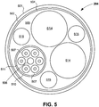
- FIG. 5 shows a cable structure which may be employed for cable 204 shown in FIG. 2 .
- cable 204 includes a cover material 501 lined inside by a moisture protection layer 502 and an EMF shielding layer 504.
- These three layers 501, 502, and 504 define and interior area 505 for optical fibers, electrical conductors, and reinforcing elements as desired.
- interior area 505 provides room for six optical fibers 507, which, together with a filler or reinforcing element 508 are grouped together in a mono coil 510 lined with a suitable protective layer 511.
- Area 505 also provides room for two conductors 514 (separate power and ground conductors) which may comprise sheathed AWG 26 copper wire for example.
- FIG. 5 also shows three strands of filler/reinforcement 515. It will be appreciated that optical fibers 507 shown in FIG. 5 comprise the continuation of fibers 212 which terminate in second connector 112 in FIG. 2 . Conductors 514 terminate in second connector 112 shown in FIG. 2 at power receiver/conditioner 232.
- This cable arrangement shown in FIG. 5 has the advantage that the bundle of optical fibers may be readily changed as desired by simply pulling the fiber 507 and filler/reinforcement strand 508, and replacing that bundle with another bundle having more or fewer fibers.
- Cable 204 shown in FIG. 5 may also be modified by using the conductive mono coil 510 and the EMF shielding 504 to replace the two copper conductors 514. This allows the cable to have a smaller diameter, or allows the area taken up by conductors 514 to be used for additional optical fibers, preferably run in one or more additional mono coils.
- the combination of optical fiber transmission elements together with the electrical conductors allows the cable to support the optical data transmission and electrical power transfer facilitated by interface 101.
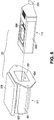
- FIGS. 6 through 9 show an example of an interface device 101 in which first connector 111 is adapted to be incorporated with the housing of another component such as CCU 104 shown in FIG. 1 .
- first connector 111 includes a housing 601 while second connector 112 includes a housing 602.
- Housings 601 and 602 each provide an enclosure for components of the respective connector.
- Housing 601 also includes a flange 604 by which first connector 111 may be secured to a component such as CCU 104 in FIG. 1 .
- Housing 601 also defines a receptacle 201 in which housing 602 for connector 112 can be inserted to place the two connectors in the operating position.
- Second connector 112 is connected to cable 204 which extends to a camera head or endoscope such as those described above.
- FIG. 7 shows an end of connector 112 which is received in receptacle 201 defined by housing 601 in FIG. 6 when the connectors are brought together in the operating position.
- This end of connector 112 includes a recess 701 in which is mounted the alignment block 217 of connector 112.
- An alignment pin 702 projects from a face of alignment block 217, while an alignment pin receiver opening 704 is also located on the face of the alignment block 217.
- a recess 706 for receiving protective cover 222 is formed between alignment pin 702 and alignment pin receiver 704.
- An end of the portion of each optical signal path in connector 112 is visible in FIG. 7 within the area of recess 706 behind the transparent protective cover 222. Each such end is defined by a circular opening 707.
- a lens retainer 708 is apparent in each such circular opening in the perspective of FIG. 7 , although components within each optical signal path are not visible in this view. Components within each optical signal path are, however, shown in the section view of FIG. 9 , as will be described below.
- FIG. 8 shows both connectors 111 and 112 aligned so that they may be brought together in the operating position.
- the connector housings (housing 601 and 602) are shown in dashed lines in FIG. 8 (as are power control circuit 228 and coil 607 for connector 111) so that the internal components of each connector are visible.
- the internal components of each connector are also shown in the section view of FIG. 9 which is taken along a vertical plane through the center longitudinal axis of the connectors 111 and 112 in the operating position.
- FIGS. 8 and 9 show alignment block 216 for connector 111 and alignment block 217 for connector 112.
- alignment block 216 includes a complementary structure to alignment block 217 with an alignment pin 802 and an alignment pin receiver opening 804.
- the alignment pin of one alignment block is received with close tolerance in the alignment pin receiver opening of the opposite alignment block.
- This alignment arrangement helps ensure proper alignment of the respective portions of the optical paths formed by the two connectors.
- alignment block 216 also includes a recess 806 in which is mounted transparent protective cover 221. An end of each optical path portion in connector 111 is also visible through the transparent protective material as circular openings although these circular openings are not labeled in the figure in view of the scale of the drawing.
- a rear side of alignment block 217 in connector 112 is visible in the view of FIG. 8 .
- This rear side is the side opposite the side shown in the view of FIG. 7 .
- the ferrules 215 for alignment block 217 are visible in FIG. 8
- the section view of FIG. 9 shows two of the ferrules associated with both alignment blocks, namely, ferrules 214 in alignment block 216 and ferrules 215 in alignment block 217.
- the section view of FIG. 9 also shows the optical lenses 219 and 220, lens retainers 708 and 808, and protective cover material 221 and 222 associated with two of the optical paths defined through the connectors in the operating position.
- the example interface device 101 shown in FIGS. 6-9 employs a circular arrangement of ferrules in each alignment block (216, 217). That is, the arrangement includes five ferrules arranged in a circle with the sixth ferrule in the center of that circular shape.
- the circular arrangement is desirable because it makes efficient use of space in the alignment blocks.
- ferrules may be arranged in any pattern in an alignment block in embodiments of the invention to suit the given application.
- FIGS. 8 and 9 omit the optical fibers which would be included in connectors 111 and 112 (as shown in FIG. 2 ) and also omit the electrical conductors extending from circuits 228 and 232.
- the fibers and conductors are omitted from these views in order to better show the remaining structure of the connectors.
- Those familiar with optical fiber connections will appreciate that the respective fiber received in a given one of the ferrules 214 or 215 would be positioned so that its end is effectively optically coupled to the respective lens 219 or 220. The fiber may or may not abut the lens depending upon the properties of the lens.
- each fiber would extend away from its respective ferrule and into cable 204.
- Each fiber in connector 111 would extend from the respective ferrule to the signal conversion unit associated with that connector (such as conversion unit 114 shown in FIGS. 1 and 2 ).
- FIGS. 6-9 includes a power transfer arrangement in which the two connectors 111 and 112 are electrically isolated from each other and power is transferred via an inductive coupling.
- the inductive coupling in this case is between planar spiral coils.
- Coil 608 is included on connector 112 and mounted with its plane parallel to a top side of housing 602 in the orientation of the figure.
- connector 111 includes a corresponding spiral coil 607.
- Coil 607 is mounted outside of receptacle 201 with its plane extending parallel to a top side of the connector in the orientation of the figure. As will be described further below in connection particularly with FIG. 9 , these locations of the coils 607 and 608 facilitate the desired inductive coupling when the connectors are in the operating position.
- FIG. 7 shows that coil 608 is mounted in a top recess 710 in connector housing 602 so that the coil does not protrude from an uppermost plane of the connector.
- Conductors 711 extend to the power receiving/conditioning circuit 232 (shown in FIG. 8 ) inside housing 602.
- this recessed arrangement for coil 608 is preferred, other forms of the invention may use a planar coil that is mounted on top of the top surface of housing 602 so that the coil protrudes somewhat from that surface.
- FIG. 9 shows that the two coils are aligned for inductive coupling when the connectors are placed in the operating position.
- the position of each coil in its respective connector allows the two coils to reside essentially parallel to each other and in alignment when the connectors are placed in the operating position.
- This alignment of coils 607 and 608 produces an inductive coupling between the two coils to allow transfer of electrical power from connector 111 to connector 112 as described above.
- connectors 111 and 112 will be held securely together in the operating position in order to form the desired interface.
- Any suitable technique or combinations of arrangements may be used within the scope of the invention to secure connectors 111 and 112 in the desired operating position to facilitate power transfer and data communication, but allow the connectors to be readily separated as desired.
- detents may be included on the exterior of one connector and cooperate with corresponding projections on the opposite connector to retain connectors 111 and 112 in the desired operating position.
- one connector may include a locking feature such as a suitable ridge and the other connector may include a cooperating latch piece adapted to reside in either a locking position in which it contacts the locking feature to retain the connectors in the operating position, or a release position in which the connectors may be separated.
- the alignment pins 702 and 802 and alignment pin receiving openings 704 and 804 may be formed from suitable material and sized to provide a friction fit which holds the two connectors together once in the operating position until a suitable separating force is applied to separate the connectors.
- the various components of an interface according to the present invention may be formed from any suitable material or combination of materials.
- the materials should be selected for compatibility with environment in which the interface is to be used or to which the interface may be subjected.
- connectors may be formed from suitable thermoplastics.
- cover 501 may comprise reinforced silicone rubber, and EMF shielding may comprise a suitable fine gauge conductive mesh.
- Filler/reinforcing strands 508 and 515 may be formed from any suitable material which is compatible with the other elements in cable 204 and provides the desired strength characteristics.
- top, bottom, upper, lower, and the like with reference to a given feature are intended only to identify a given feature and distinguish that feature from other features. Unless specifically stated otherwise, such terms are not intended to convey any spatial or temporal relationship for the feature relative to any other feature.
- each may be used in the following claims for convenience in describing characteristics or features of multiple elements, and any such use of the term “each” is in the inclusive sense unless specifically stated otherwise. For example, if a claim defines two or more elements as “each” having a characteristic or feature, the use of the term “each” is not intended to exclude from the claim scope a situation having a third one of the elements which does not have the defined characteristic or feature.
Landscapes
- Physics & Mathematics (AREA)
- Health & Medical Sciences (AREA)
- Life Sciences & Earth Sciences (AREA)
- Optics & Photonics (AREA)
- Surgery (AREA)
- General Physics & Mathematics (AREA)
- Engineering & Computer Science (AREA)
- Biophysics (AREA)
- Molecular Biology (AREA)
- Pathology (AREA)
- Nuclear Medicine, Radiotherapy & Molecular Imaging (AREA)
- Biomedical Technology (AREA)
- Heart & Thoracic Surgery (AREA)
- Medical Informatics (AREA)
- Radiology & Medical Imaging (AREA)
- Animal Behavior & Ethology (AREA)
- General Health & Medical Sciences (AREA)
- Public Health (AREA)
- Veterinary Medicine (AREA)
- Computer Networks & Wireless Communication (AREA)
- Endoscopes (AREA)
Description
- The invention relates to electrical power and data interfaces with observation instruments, including optical instruments such as endoscopic devices. More particularly, the invention relates to connectors which are used to provide an interface between an electrically operated instrument and control or related equipment for the instrument. The invention also relates to methods for providing such an interface.
- Observation instruments, including optical instruments such as endoscopes, borescopes, and exoscopes may include an electronic imaging device located, for example, at the distal end of an elongated shaft or in a camera head which is connected to an elongated shaft. Whether positioned at the distal end of the endoscope shaft or in the camera head, the electronic imaging device may be one or more charge coupled devices (CCDs) or CMOS imaging devices together with other electronic components. Other electronic devices such as LED or other light sources may be included in the instrument. The camera head (or an instrument body or handle in the case of some observation instruments) is typically connected via a suitable cable to a camera control unit, commonly referred to as a "CCU." The cable provides paths for carrying electrical power to the camera head and data signals to and from the camera head. In particular, image data captured by the imaging device is transmitted over the cable to the CCU for processing and ultimately for display on monitors which are connected directly to the CCU or to an intermediate monitor driving device. Control signals and power for operating the electronic components in the instrument may be transmitted over the cable from the CCU to the scope and/or camera head.
- It is known in the art to transmit data signals from an endoscope to a CCU in the form of optical signals rather than electrical signals.
US 2015/0250378 A1 , for example, uses a cable between a camera head and CCU which includes optical fibers for carrying optical data signals from the camera head to the CCU. The camera head in this example includes circuitry for converting the captured image data from the electronic data signals generated by the imaging device to optical data signals which are then inserted into the optical fibers of the cable.US 2015/0250378 A1 also discloses that the cable from the camera head to CCU may include electrical signal paths in addition to the optical signal paths. -
US 2008/0225134 A1 shows another endoscopic system having a cable between the CCU and camera head which includes both electrical signal paths and an optical path. In this case, the optical path is used to provide illumination light to the endoscope. - In
US 8,488,969 B1 , an intrapersonal data communication system is described (title; column 1, lines 30 through 32; column 6, lines 14 through 17; etc.). The system comprises an opticaldigital signal adapter 401 or a signal converter 400 within a local device and an optical digital signal link 402 (column 25, lines 7 through 51;Figures 4A, 4B, 4C ). Theoptical signal link 402 comprises electrical lines (no reference numeral), optical fibers 418 and non-contact optical connectors 422, 423 (Column 25, lines 52 and 57;Figures 4A, 4B, 4C ). At an interface between theoptical signal adapter 401 or the signal converter 400 and the opticaldigital signal link 402, electrical power is transferred via connector elements 424, 425 (column 25, lines 52 through 54;Figures 4A, 4B, 4C ), and optical digital signals pass through collimating lenses 420, 427 and focusing lenses 426, 421 and transparent windows 428, 429 at both sides of the interface (column 27, lines 3 through 37;Figure 4A, 4B, 4C ). - In
EP 1 989 989 A2 , a medical apparatus comprising an endoscope body is described (paragraphs [0001], [0011]). An endoscope 21 includes a body unit 22 held by an endoscope holding section 20 (paragraph [0026];Figure 1 ). The body unit 22 comprises an insertion-section-side body 50 as a first member and a power unit 51 as a second member (paragraph [0034];Figure 2 ). The power unit 51 is provided with a chassis 85 having a cavity portion 86 (paragraph [0058];Figure 4 ). When an engaging member 63 of the insertion-section body 50 is inserted into the cavity portion 86 (paragraph [0058];Figure 4 ), afirst wiper 101 provided in the cavity portion 86 removes moisture disposed adjacent electrical terminal portions 97 at the insertion-section body 50 (paragraph [0065];Figure 4 ) and a light guide 46 in the insertion portion 50 guiding illumination light (paragraphs [0036], [0037];Figure 4 ) and alight guide 115 in the power unit 51 (paragraph [0035];Figure 4 ) are optically coupled (paragraph [0076];Figure 4 ). - In
US 2015/0168655 A1 , acable assembly 100 comprising anoptical connector assembly 101 employing a translating element 110 is described (paragraph [0039];Figure 1 ). The optical translating element 110 comprises a coupling surface 126 and lenses 122 exposed at the coupling surface 126 (paragraph [0042];Figure 1 ). Furthermore, theoptical connector assembly 101 comprises electrical contacts 141a, 141b configured to pass electrical power and/or data (paragraph [0046];Figure 1 ). - In
US 2011/0193948 A1 , an endoscope system 10 for wirelessly transmitting energy and data is described (paragraph [0051];Figure 1 ). On an endoscope 12, a transponder/transceiver 20 is mounted and communicates with a camera head transponder/transceiver 24 mounted on a detachable camera head 14 (paragraph [0051];Figure 1 ). An endoscope 290 houses a wire coil 320, another wire coil 370 is positioned in a camera head 360 (paragraph [0082];Figure 4 ). Power is supplied to the camera head coil 370 through a camera cable 390 and wirelessly transmitted across the camera-endoscope interface to the endoscope wire coil 320 inductively (paragraph [0082];Figure 4 ). The endoscope can rotate freely in a coupling mechanism 350 at the camera head 360 (paragraph [0082]). - In
US 2016/0341952 A1 , an electronic endoscope apparatus 1 comprising an electronic endoscope 2 and a processor device 3 is described (paragraphs [0005], [0014], [0028],figure 1 ). A connector 13 at the end of a universal cord 12 of the electronic endoscope 2 can be connected to a connector 14 of the processor device 3 (paragraph [0029],figure 1 ). The universal cord 12 includes a wiring group 30 transmitting operating power and control signals and image signals (paragraph [0034],figure 2 ). The connector 13 of the electronic endoscope 2 comprises an input/output unit 31, and the connector 14 of the processor device 3 comprises an input/output unit 33 (paragraphs [0036], [0037],figure 2 ). Coils 40 provided in each of the input/output units 31, 33 of the connectors 13, 14 face each other and transmit power by using electromagnetic induction (paragraph [0041],figure 2 ). A light-emitting element 41 a is provided on a signal output side of each of the input/output units 31, 33, and a light-receiving element 41b is provided on an input side of each of the input/output units 31, 33 (paragraph [0042],figure 2 ). The light-emitting elements 41 a and the light-receiving elements 41b transmit signals by using light (paragraph [0042],figure 2 ). A contact part 32 of the connector 13 of the endoscope 2 is connected to ground of the electronic endoscope 2 (paragraph [0036],figure 2 ). A contact part 34 of the connector 14 of the processor device 3 is connected to a housing 36 of the grounded processor device 3 through a capacitor C1 (paragraph [0038],figure 2 ). In a state in which the connectors 13, 14 are connected to each other, the contact parts 32, 34 of the connectors 13, 14 come into contact with each other, so that ground of the electronic endoscope 2 and the housing 36 of the processor device 3 are electrically connected to each other (paragraph [0044]). Thereby, in influence of noises on the electronic endoscope 2 is reduced (paragraph [0045]). - In
US 2014/0184771 A1 ) a system for transferring power and data for a camera used in endoscopic surgery is described (paragraph [002]). An endoscopic imaging system 10 comprises a camera head 12 and a camera control unit 14, wherein the camera head 12 may be used together with an endoscope (paragraph [0028],figure 1 ). Data are transmitted via extremely high frequency (e.g. 60 GHz) radio communication (paragraph [0038]). Power is inductively transferred from a transmitter coil 158 in abody 114 of a camera control unit connector 102 of the camera control unit 14 to a receiver coil 154 related to the camera head 12 (paragraphs [0034], [0035], [0042]). An electromagnetic spring clip 126 is mounted between a capacitor 124 and a shield box 116, engages an exposedmetal shield 106 of acamera head connector 100 and controls undesired electromagnetic emission and protects the camera system from electromagnetic interference (paragraph [0035]). - In
EP 1 927 313 A1 , an endoscope system 1 comprising a flexible endoscope 3A and an endoscope system controlling device 5 performing signal processing for an image pickup device built into the endoscope 3A is described (paragraph [0018],figure 1 ). A "general connector portion" 52 of a "tube unit" 19 (cf. paragraph [0024]; infigures 1 ,2 : like a cable) is coupled to a "connector portion" 51 of the "endoscope main unit" 18 (paragraph [0072],figure 2 ). The connector portion 51 of the endoscope main unit 18 and the general connector portion 52 of the "tube unit" 19 comprise coils forming contactless transmitting sections 72a, 72b (paragraph [0072], [0074], [0076]). Power and signals are transmitted via the contactless transmitting sections 72a, 72b (paragraphs [0075], [0077]). - Medical devices such as endoscopes require an electrical isolation barrier between the CCU and camera head/endoscope. This electrical isolation barrier is required to ensure that an inappropriate electrical signal is not inadvertently applied to the endoscope and thus to the patient in which the endoscope is used. Where a cable running between the CCU and endoscope includes electrical signal paths, such as in both of the above-mentioned U.S. patent application publications, it has been necessary for the electrical isolation barrier to be included in the circuitry of the CCU. This requirement of the electrical isolation barrier in the CCU greatly complicates the circuitry of the device.
- It is an object of the invention to provide an interface to an electrically powered instrument in which the interface is robust and supports high data transfer rates, particularly in the direction from the instrument to control equipment for the instrument. Another object of the invention is to provide such an interface which includes an electrical isolation barrier. The invention is defined in the appended claims.
- An interface device according to one aspect of the present invention includes a first connector and a second connector adapted to be joined together in an operating position. One or more first optical data conduits such as optical fibers extend through the first connector, with each first optical data conduit terminating at a respective first optical conduit end which is operatively aligned with a respective first optical lens. One or more second optical data conduits (which may similarly comprise optical fibers) extend through the second connector, with each second optical data conduit terminating at a respective second optical conduit end which is operatively aligned with a respective second optical lens. When the first connector and second connector are joined in the operating position, each respective second optical data conduit and respective second optical lens are aligned for optical coupling across a coupling region with one of the first optical conduits and respective first optical lens. This arrangement of optical data conduits and optical lenses produces an expanded beam optical data communication path across the two connectors for each pair of aligned first and second optical conduits.
- As used in the preceding paragraph and elsewhere in this disclosure and following claims, the designation "operatively aligned" with reference to an optical fiber end and an optical lens means that the fiber end is aligned so that the light signal exiting the fiber end is incident on the lens surface so that the lens provides the desired optical function. The function of the optical lenses will be described further below in connection with the representative embodiments. The designation "optical coupling" in the present disclosure and accompanying claims means an arrangement in which light exiting a fiber end passes through the corresponding optical lenses and is directed into the end of the corresponding optical fiber.
- In addition to the optical elements according to this first aspect of the invention, the interface also includes an electrical power transfer arrangement. This arrangement includes a first electrical power transfer element mounted on the first connector and a second electrical power transfer element mounted on the second connector. These electrical power transfer elements are located in a power transfer orientation with respect to each other when the first connector and second connector are joined in the operating position, and this facilitates the transfer of electrical power from one of the connectors to the other.
- The expanded beam optical data communication arrangement together with the electrical power transfer arrangement has the advantage that very high data transfer rates are possible across the interface, while electrical power for electronic components may also be transferred across the interface. High data transfer rates are particularly advantageous where the interface is used in medical instrument systems such as video endoscope systems in which a high-resolution image is captured with electronic components at the instrument, and then the voluminous image data is transferred to a control system for processing. The expanded beam optical communication arrangement accommodates the high data rates which may be required while the power transfer arrangement accommodates the transfer of electrical power to the imaging and optical signal generation elements required for image collection and optical data communication.
- Furthermore, in some embodiments of the interface, the electrical power transfer elements may be configured so that the electrical power is transferred inductively across the elements. Thus all electrical circuits associated with the first connector may be electrically isolated from all electrical circuits associated with the second connector. With the data all communicated along optical communication paths across the interface, and with the electrical circuits electrically isolated, the interface forms an electrical isolation barrier. The interface may be placed at any one of a number of alternative locations in a medical device system such as an endoscopic system to eliminate the need for a complicated electrical isolation barrier in the system control equipment.
- Another aspect of the invention provides a single connector similar to one of the connectors described above. Such a connector has particular application in making a connection with a complementary connector to provide a detachable interface between an electrically powered instrument and a control system for the instrument. A connector according to this second aspect of the invention includes a connector body and an optical data conduit extending through the connector body and terminating at a conduit end within the connector body. An optical lens is included in the connector body and is operatively aligned with the conduit end. An electrical power transfer element is also mounted within the connector body.
- A connector according to either of the above aspects of the present invention may include a cable connected to the connector body. The cable may include continuations of the optical data conduits of the connector and also electrical conductors for carrying the desired electrical power signal to or from the connector. Of course, where electrical isolation is provided across a connection made by the connectors, all electrical circuits included in the connector are electrically isolated within the connector body aside from electrical continuity to the power conductor arrangement within the cable.
- Another aspect of the invention includes a method of providing an interface between an electrically powered instrument and a control system for the instrument. A method according to this additional aspect of the invention includes placing a first connector in an operating position with respect to a second connector and directing optical data along an optical path defined through the first and second connectors in the operating position. This optical path includes a first optical conduit extending through the first connector, second optical conduit extending through the second connector, and a coupling region interposed between the first optical conduit and the second optical conduit. A method according to this additional aspect of the invention further includes expanding an area of an optical signal (the signal carrying the optical data) at a first side of the coupling region and reducing the area of the optical signal at a second side of the coupling region. Additionally, electrical power is transferred from a first power transfer element included with the first connector to a second power transfer element included with the second connector.
- In one implementation of an interface according to any of the foregoing aspects of the invention, the first connector defines a receptacle. In these implementations when the connectors are in the operating position at least a portion of the second connector is received within the receptacle defined by the first connector. Also, where the interface is employed in an endoscopic system, the connector defining the receptacle may advantageously be contained within a housing for a camera control unit of the endoscopic system.
- As noted above, embodiments of the interface may employ an inductive coupling between the power transfer elements in order to maintain electrical isolation between the two complementary connectors. Any suitable inductive coupling arrangement may be employed according to the invention. In one implementation, the first electrical power transfer element comprises a first planar spiral coil and the second electrical power transfer element comprises a second planar spiral coil. In these planar coil implementations, the first planar spiral coil may be aligned parallel to a first side of the first connector and the second planar spiral coil may be aligned parallel to a first side of the second connector. The two planar spiral coils align with each other sufficiently when the connectors are in the operating position to provide inductive coupling between the coils. Alternatively to the planar coil implementations, the electrical power transfer elements may comprise helical coils. In particular, the first electrical power transfer element may comprise a first helical coil and the second electrical power transfer element may comprise a second helical coil adapted to align with the first helical coil and reside within an area defined by the first helical coil when the first connector and the second connector are joined in the operating position.
- In any of the different aspects of the present invention, a suitable transparent protective material may be mounted on the respective connector to protect the optical lens or lenses. In particular, the transparent protective layer may be mounted on the respective connector in position to reside between each optical lens of that connector and the opposite connector when the connectors are in the operating position.
- In any of the different aspects of the present invention, the electrically powered instrument may be an observation instrument. Such an observation instrument might be an optical instrument such as a video camera, endoscope, exoscope, or borescope.
- These and other advantages and features of the invention will be apparent from the following description of representative embodiments, considered along with the accompanying drawings.
-
-
FIG. 1 is a block diagram showing an endoscopic system incorporating an interface device according to an aspect of the present invention. -
FIG. 2 is a schematic diagram of the interface device shown inFIG. 1 . -
FIG. 3 is a schematic representation showing a power transfer element arrangement according to one embodiment of the invention. -
FIG. 4 is a schematic representation showing a power transfer element arrangement according to another embodiment of the invention. -
FIG. 5 is a schematic representation of a cross-section of a cable that may be employed with the interface device shown inFIG. 2 . -
FIG. 6 is a view in perspective showing a pair of connectors making up an interface device according to an embodiment of the invention. -
FIG. 7 is a view in perspective showing an end of one of the connectors shown inFIG. 6 . -
FIG. 8 is a view in perspective similar toFIG. 6 , but showing the housing of each connector and certain other features in dashed lines to show the internal components of the connectors and their position relative to the respective housing. -
FIG. 9 is a view in section though the connectors shown inFIGS. 6 and8 in an operating position, the section being taken along a vertical plane through the center longitudinal axis of the connectors. - The present invention is disclosed below in the context of an endoscopic system. Embodiments also include apparatus and methods for other electrically powered instruments. Thus, optical instruments (e.g., video cameras, endoscopes, exoscopes, borescopes) employing high-resolution imaging (e.g., a 4K resolution design) is an illustrative, but non-limiting example embodiment. More generally, an interface or connector within the scope of the following claims may have application in connection with any observation instrument.
-
FIG. 1 shows anendoscopic system 100 employing aninterface device 101 according to the present invention.System 100 includes a camera control unit ("CCU") 104, acamera head 105, and anendoscope 106.CCU 104 is connected to send a signal to amonitor control unit 108 connected tomonitors 109 for displaying images fromcamera head 105 orendoscope 106. -
Interface device 101 is interposed betweenCCU 104 andcamera head 105 and functions as a detachable link for data communication and power transfer between the CCU and camera head. Both the data communication and power transfer functions are preferably provided acrossinterface device 101 while the device also maintains an electrical isolation barrier tocamera head 105 andendoscope 106. Data is communicated in the form of optical data signals S inFIG. 1 , both fromcamera head 105 and/orendoscope 106 toCCU 104 and also preferably in the opposite direction from the CCU to the camera head and/or endoscope. Electrical power (P inFIG. 1 ) is transferred only in the direction fromCCU 104 tocamera head 105 and/orendoscope 106. The data transmission rates possible via optical data transmission in the direction from thecamera head 105 toCCU 104 is particularly advantageous for transmitting the large amounts of image data that may be collected by an imaging device or multiple imaging devices (not shown) associated withendoscope 106 orcamera head 105. Data which may be transmitted fromCCU 104 tocamera head 105 and/orendoscope 106 may comprise control instructions and operational instructions and data, which may typically be of lesser volume as compared to the image data transmitted in the opposite direction. -
Interface device 101 includes afirst connector 111 and asecond connector 112 which may be connected in an operating position to facilitate the desired data communication and power transfer. This operating position is schematically indicated inFIG. 1 and will be described in further detail below with reference particularly toFIGS. 2 and9 . The twoconnectors camera head 105 andendoscope 106 fromCCU 104 and then reconnected in the operating position as desired. For example,connector 112 may be detached fromconnector 111 in preparation for sterilizingcamera head 105 and/orendoscope 106. Once the sterilization or other process or activity requiring detachment is complete,connectors CCU 104 andcamera head 105/endoscope 106. - The position of
interface device 101 shown inFIG. 1 betweenCCU 104 andcamera head 105 is intended to indicate that the device may be interposed at any position between those two devices. One embodiment that will be described further below in connection withFIGS. 2 and6-9 incorporatesfirst connector 111 in a housing forCCU 104. In this embodiment,first connector 111 may be formed as a receptacle in a housing forCCU 104 and adapted to receivesecond connector 112 in the operating position.Second connector 112 in this embodiment is connected to a suitable cable having optical conduits such as optical fibers for carrying the optical signals and suitable conductors for conducting electrical power tocamera head 105. Such a cable will be described below in connection withFIG. 5 . However it should be borne in mind that the invention is not limited to this arrangement in which one of the connectors is incorporated in the CCU or one of the other devices in the system. - Before moving on to describe further details of
interface device 101, it should be noted that bothCCU 104 andcamera head 105 include components for supporting the interface. In particular,CCU 104 includes asignal conversion unit 114 to convert incoming optical signals from the direction ofcamera head 105 to electrical signals for further processing and to convert electrical signals generated at the CCU to optical signals for transmission to the camera head and/orendoscope 106. Similarlycamera head 105 includes asignal conversion unit 115 for converting image data and other signals to optical signals for transmission toCCU 104 and for converting incoming optical signals from the CCU to electrical signals for use in the camera head orendoscope 106. -
FIG. 2 shows an embodiment ofinterface 101 withfirst connector 111 incorporated in ahousing 200 forCCU 104.First connector 111 defines areceptacle 201 inCCU housing 200 which is adapted to receivesecond connector 112 in the operating position shown in the figure.Second connector 112 in this illustrated embodiment is connected to acable 204 which includes elements for carrying the optical signals and electrical signals tocamera head 105 shown inFIG. 1 . Further details of a suitable cable will be described below with reference toFIG. 5 . - In order to support the optical data signal communications through
interface 101,CCU 104 includessignal conversion unit 114.Signal conversion unit 114 includes an electro-optical converter 205 for converting electrical signals fromCCU 104 to optical signals for transmission in the direction tocamera head 105.Signal conversion unit 114 also includes an opto-electrical converter 206 for converting optical signals received fromcamera head 105 and/orendoscope 106 to electrical signals for processing in other elements (not shown) ofCCU 104. The electro-optical converter 205 and opto-electrical converter 206 included insignal conversion unit 114 are well known in the art. Thus these signal conversion elements will be described herein only generally so as not to obscure the present invention in unnecessary detail. - The embodiment shown in
FIG. 2 includes six different optical signal paths. A portion of one such optical signal path is shown within dashedbox 208 inFIG. 2 . Each optical signal path is defined in part by a firstoptical fiber 211 associated withfirst connector 111 and a secondoptical fiber 212 associated withsecond connector 112. Firstoptical fiber 211 terminates infirst connector 111 in asuitable ferrule 214, while secondoptical fiber 212 terminates insecond connector 112 in acorresponding ferrule 215. Eachferrule 214 infirst connector 111 is mounted in analignment block 216 mounted in that connector. Similarly, eachferrule 215 insecond connector 112 is mounted in analignment block 217 mounted in that second connector. Eachalignment block connectors optical fiber 211 with the terminating end of thecorresponding fiber 212 in the respective optical signal path. - Each optical signal path in this illustrated form of the invention also includes an expanded beam coupling arrangement for coupling the optical signal carried through one
fiber optical lens 219 aligned with the terminating end ofoptical fiber 211, and anoptical lens 220 aligned with the terminating end ofoptical fiber 212.Optical lens 219 for an incoming optical signal fromfiber 211 in the lowermost optical signal path shown in dashedbox 208 inFIG. 2 is operable to expand and collimate the incoming optical signal to distribute the optical power of the signal over a larger area (larger than the fiber) within the coupling region defined between the twolenses optical lens 220 serves to focus the expanded beam back down to the area defined by the terminating end ofoptical fiber 212 in which the signal is to be inserted. Thus the arrangement of operatively alignedfiber 211 andoptical lens 219, and corresponding operatively alignedfiber 212 andoptical lens 220 along a given optical path provides an optical coupling that couples a light signal exiting one of the fiber ends into the end of the corresponding fiber. - It should be noted here that although the representative embodiment shown in
FIG. 2 and embodiments described below in connection withFIGS. 6-9 show ball lenses forlenses FIG. 2 only for the path in dashedbox 208. The reference signs for the path in dashedbox 208 apply to the corresponding elements of the other five optical signal paths. -
First connector 111 andsecond connector 112 each includes a suitable protective transparent cover extending transverse to each signal path. The protective cover forfirst connector 111 is shown at 221 inFIG. 2 , while the protective cover forsecond connector 112 is shown at 222. Protective covers 221 and 222 may comprise Sapphire or any other suitable material and forms an exterior surface of the respective connector covering the adjacent optical lens. This arrangement protectsoptical lenses connectors FIG. 2 . - In the embodiment of the invention shown in
FIG. 2 , first andsecond connectors air gap 223 betweencovers box 208, includes a portion traversing thisair gap 223.Air gap 223 is used to prevent contact between thecovers connectors covers covers connectors - The example provided in
FIG. 2 shows four optical paths (the upper four in the figure) dedicated for optical transmissions in the direction fromcamera head 105 toCCU 104. These optical transmissions (in the illustrated use in anendoscopic system 100 inFIG. 1 ) will include image data which may include a very large volume of data depending upon the resolution of the imaging device associated withcamera head 105 orendoscope 106 and on other factors. In this example, two optical paths (the lower two inFIG. 2 ) are dedicated for the transmission of optically encoded data in the direction fromCCU 104 tocamera head 105. This data may include instructions and control signals forcamera head 105 and/orendoscope 106. It should be appreciated that the invention is not limited to any particular number of optical paths or any particular optical encoding technique. AlthoughFIG. 2 suggests that each optical signal path accommodates only unidirectional data transmission, other embodiments may include bidirectional transmission over each optical path. Also, various optical signal encoding techniques may be employed to further increase the rate at which data may be transmitted throughinterface 101. For example wave division multiplexing techniques or other multiplexing techniques may be used to transmit multiple different data streams contained in a single multiplexed signal across a given optical signal path. Of course the receiving and transmitting elements inCCU 104 andcamera head 105 must support the respective encoding and transmission technique employed across the optical signal paths. For example, signal multiplexing techniques employ a multiplexer at the transmission side and a demultiplexer at the receiving side. -
Interface 101 shown inFIG. 2 also includes an arrangement for wirelessly transferring power fromfirst connector 111 on the CCU side of the interface tosecond connector 112 on the camera head side of the interface. This electrical power supplied tocamera head 105 and/orendoscope 106 is necessary for operating electronic elements included in the camera head and endoscope. For example, the electrical power may be used to operate an imaging device and related electronic components incamera head 105 orendoscope 106, opto-electrical and electro-optical converters associated with the camera head, and illumination elements (not shown in the figures) associated with the camera head and/or endoscope. The wireless power transfer arrangement includes a firstpower transfer element 227 included withfirst connector 111, and apower control circuit 228 connected to the first power transfer element. A secondpower transfer element 230 is included withsecond connector 112 together with a power receiver orconditioner 232. When the twoconnectors FIG. 2 , the twopower transfer elements Power control circuit 228 is operable to supply a suitable driving signal to cause a variable current flow in firstpower transfer element 227 and consequent electromagnetic field around the first power transfer element. This field produced around firstpower transfer element 227 induces a current in secondpower transfer element 230. The induced current is conditioned by power receiver/conditioner circuit 232 to provide a suitable power signal for transmission to the camera head over electrical conductors included incable 204. For example, power receiver/conditioner circuit 232 may comprise a suitable rectifying circuit for converting the signal induced in secondpower transfer element 230 to a DC voltage signal suitable for use by electronic components included incamera head 105 and endoscope 106 (shown inFIG. 1 ). - This preferred arrangement of wireless power transfer between
connectors connectors CCU 104 andcamera head 105/endoscope 106. This electrical isolation barrier included ininterface 101 obviates the need for an electrical isolation barrier in the circuitry ofCCU 104, which is typically complicated and serves as a constraint on CCU design. - It should be appreciated that although the wireless power transfer arrangement across
connectors connectors FIG. 2 . Thus a system such assystem 100 inFIG. 1 employing a data and power interface having a contact-type power transfer arrangement would have to provide an electrical isolation barrier outside of the interface. -
FIGS. 3 and 4 show alternative arrangements for first and second power transfer elements, 227 and 230, respectively, shown inFIG. 2 . The high-level schematic diagram ofFIG. 3 shows that the first and second power transfer elements may each comprise a suitable planar spiral coil. In particular, a firstplanar spiral coil 301 comprises the power transfer element associated withfirst connector 111, and is aligned with its plane parallel to afirst side 302 of that connector. Thisside 302 forms an inner surface of the receptacle defined byfirst connector 111 in this example. A secondplanar spiral coil 303 comprising the power transfer element associated withsecond connector 112 is mounted parallel to aside surface 304 of that connector. Whenfirst connector 111 andsecond connector 112 are placed in the operating position indicated inFIG. 3 , thespiral coil 301 comprising the first power transfer element aligns with thespiral coil 303 comprising the second power transfer element so that the two coils are inductively coupled. - The high-level schematic diagram in
FIG. 4 shows an alternative arrangement in which ahelical coil 401 comprises the power transfer element associated with thefirst connector 111. Thishelical coil 401 protrudes fromfirst connector 111 into the area defined by the receptacle of the first connector. A secondhelical coil 402 comprises the power transfer element associated withsecond connector 112.Helical coil 402 in this embodiment has a diameter large enough to receivehelical coil 401. Whenfirst connector 111 andsecond connector 112 are placed in the operating position with the second connector received in the receptacle defined by the first connector,helical coil 401 comprising the first power transfer element aligns with and extends intohelical coil 402 comprising the second power transfer element so that the two coils are inductively coupled to facilitate the desired power transfer. Of course other arrangements within the scope of the present invention may reverse the helical coils so that a helical coil onconnector 112 extends into the area defined by a larger diameter helical coil onconnector 111. - The schematic representation of
FIG. 5 shows a cable structure which may be employed forcable 204 shown inFIG. 2 . In this example,cable 204 includes acover material 501 lined inside by amoisture protection layer 502 and anEMF shielding layer 504. These threelayers interior area 505 for optical fibers, electrical conductors, and reinforcing elements as desired. In particular,interior area 505 provides room for sixoptical fibers 507, which, together with a filler or reinforcingelement 508 are grouped together in amono coil 510 lined with a suitableprotective layer 511.Area 505 also provides room for two conductors 514 (separate power and ground conductors) which may comprise sheathed AWG 26 copper wire for example. The example ofFIG. 5 also shows three strands of filler/reinforcement 515. It will be appreciated thatoptical fibers 507 shown inFIG. 5 comprise the continuation offibers 212 which terminate insecond connector 112 inFIG. 2 .Conductors 514 terminate insecond connector 112 shown inFIG. 2 at power receiver/conditioner 232. - This cable arrangement shown in
FIG. 5 has the advantage that the bundle of optical fibers may be readily changed as desired by simply pulling thefiber 507 and filler/reinforcement strand 508, and replacing that bundle with another bundle having more or fewer fibers.Cable 204 shown inFIG. 5 may also be modified by using theconductive mono coil 510 and the EMF shielding 504 to replace the twocopper conductors 514. This allows the cable to have a smaller diameter, or allows the area taken up byconductors 514 to be used for additional optical fibers, preferably run in one or more additional mono coils. In any event, the combination of optical fiber transmission elements together with the electrical conductors allows the cable to support the optical data transmission and electrical power transfer facilitated byinterface 101. -
FIGS. 6 through 9 show an example of aninterface device 101 in whichfirst connector 111 is adapted to be incorporated with the housing of another component such asCCU 104 shown inFIG. 1 . As shown inFIG. 6 ,first connector 111 includes ahousing 601 whilesecond connector 112 includes ahousing 602.Housings Housing 601 also includes aflange 604 by whichfirst connector 111 may be secured to a component such asCCU 104 inFIG. 1 .Housing 601 also defines areceptacle 201 in whichhousing 602 forconnector 112 can be inserted to place the two connectors in the operating position.Second connector 112 is connected tocable 204 which extends to a camera head or endoscope such as those described above. - The perspective of
FIG. 7 shows an end ofconnector 112 which is received inreceptacle 201 defined byhousing 601 inFIG. 6 when the connectors are brought together in the operating position. This end ofconnector 112 includes arecess 701 in which is mounted thealignment block 217 ofconnector 112. Analignment pin 702 projects from a face ofalignment block 217, while an alignmentpin receiver opening 704 is also located on the face of thealignment block 217. Arecess 706 for receivingprotective cover 222 is formed betweenalignment pin 702 andalignment pin receiver 704. An end of the portion of each optical signal path inconnector 112 is visible inFIG. 7 within the area ofrecess 706 behind the transparentprotective cover 222. Each such end is defined by acircular opening 707. Alens retainer 708 is apparent in each such circular opening in the perspective ofFIG. 7 , although components within each optical signal path are not visible in this view. Components within each optical signal path are, however, shown in the section view ofFIG. 9 , as will be described below. -
FIG. 8 shows bothconnectors housing 601 and 602) are shown in dashed lines inFIG. 8 (as arepower control circuit 228 andcoil 607 for connector 111) so that the internal components of each connector are visible. The internal components of each connector are also shown in the section view ofFIG. 9 which is taken along a vertical plane through the center longitudinal axis of theconnectors -
FIGS. 8 and9 show alignment block 216 forconnector 111 andalignment block 217 forconnector 112. As is apparent fromFIG. 8 ,alignment block 216 includes a complementary structure to alignment block 217 with analignment pin 802 and an alignmentpin receiver opening 804. When the twoconnectors FIG. 9 , the alignment pin of one alignment block is received with close tolerance in the alignment pin receiver opening of the opposite alignment block. This alignment arrangement helps ensure proper alignment of the respective portions of the optical paths formed by the two connectors. As shown inFIG. 8 ,alignment block 216 also includes arecess 806 in which is mounted transparentprotective cover 221. An end of each optical path portion inconnector 111 is also visible through the transparent protective material as circular openings although these circular openings are not labeled in the figure in view of the scale of the drawing. - A rear side of
alignment block 217 inconnector 112 is visible in the view ofFIG. 8 . This rear side is the side opposite the side shown in the view ofFIG. 7 . Theferrules 215 foralignment block 217 are visible inFIG. 8 , while the section view ofFIG. 9 shows two of the ferrules associated with both alignment blocks, namely,ferrules 214 inalignment block 216 andferrules 215 inalignment block 217. The section view ofFIG. 9 also shows theoptical lenses lens retainers protective cover material - The
example interface device 101 shown inFIGS. 6-9 employs a circular arrangement of ferrules in each alignment block (216, 217). That is, the arrangement includes five ferrules arranged in a circle with the sixth ferrule in the center of that circular shape. The circular arrangement is desirable because it makes efficient use of space in the alignment blocks. However, ferrules may be arranged in any pattern in an alignment block in embodiments of the invention to suit the given application. - It should be noted here that both
FIGS. 8 and9 omit the optical fibers which would be included inconnectors 111 and 112 (as shown inFIG. 2 ) and also omit the electrical conductors extending fromcircuits ferrules respective lens connector 112 each fiber would extend away from its respective ferrule and intocable 204. Each fiber inconnector 111 would extend from the respective ferrule to the signal conversion unit associated with that connector (such asconversion unit 114 shown inFIGS. 1 and2 ). - The embodiment shown in
FIGS. 6-9 includes a power transfer arrangement in which the twoconnectors Coil 608 is included onconnector 112 and mounted with its plane parallel to a top side ofhousing 602 in the orientation of the figure. Although it is largely obscured inFIG. 6 bypower control circuit 228,connector 111 includes acorresponding spiral coil 607.Coil 607 is mounted outside ofreceptacle 201 with its plane extending parallel to a top side of the connector in the orientation of the figure. As will be described further below in connection particularly withFIG. 9 , these locations of thecoils -
FIG. 7 shows thatcoil 608 is mounted in atop recess 710 inconnector housing 602 so that the coil does not protrude from an uppermost plane of the connector.Conductors 711 extend to the power receiving/conditioning circuit 232 (shown inFIG. 8 ) insidehousing 602. Although this recessed arrangement forcoil 608 is preferred, other forms of the invention may use a planar coil that is mounted on top of the top surface ofhousing 602 so that the coil protrudes somewhat from that surface. -
FIG. 9 shows that the two coils are aligned for inductive coupling when the connectors are placed in the operating position. In particular, the position of each coil in its respective connector allows the two coils to reside essentially parallel to each other and in alignment when the connectors are placed in the operating position. This alignment ofcoils connector 111 toconnector 112 as described above. - Regardless of the power transfer arrangement that may be used in a given embodiment of the present invention, and regardless of the number of optical signal paths employed for data communications across
interface device 101,connectors connectors connectors FIGS. 6-9 , the alignment pins 702 and 802 and alignmentpin receiving openings - The various components of an interface according to the present invention may be formed from any suitable material or combination of materials. The materials should be selected for compatibility with environment in which the interface is to be used or to which the interface may be subjected. For example, connectors may be formed from suitable thermoplastics. With regard to
cable 204 shown inFIG. 5 , cover 501 may comprise reinforced silicone rubber, and EMF shielding may comprise a suitable fine gauge conductive mesh. Filler/reinforcingstrands cable 204 and provides the desired strength characteristics. - As used herein, whether in the above description or the following claims, the terms "comprising," "including," "carrying," "having," "containing," "involving," and the like are to be understood to be open-ended, that is, to mean including but not limited to. Also, it should be understood that the terms "about," "substantially," and like terms used herein when referring to a dimension or characteristic of a component indicate that the described dimension/characteristic is not a strict boundary or parameter and does not exclude variations therefrom that are functionally similar. At a minimum, such references that include a numerical parameter would include variations that, using mathematical and industrial principles accepted in the art (e.g., rounding, measurement or other systematic errors, manufacturing tolerances, etc.), would not vary the least significant digit.
- Any use of ordinal terms such as "first," "second," "third," etc., in the following claims to modify a claim element does not by itself connote any priority, precedence, or order of one claim element over another, or the temporal order in which acts of a method are performed. Rather, unless specifically stated otherwise, such ordinal terms are used merely as labels to distinguish one claim element having a certain name from another element having a same name (but for use of the ordinal term).
- In the above descriptions and the following claims, terms such as top, bottom, upper, lower, and the like with reference to a given feature are intended only to identify a given feature and distinguish that feature from other features. Unless specifically stated otherwise, such terms are not intended to convey any spatial or temporal relationship for the feature relative to any other feature.
- The term "each" may be used in the following claims for convenience in describing characteristics or features of multiple elements, and any such use of the term "each" is in the inclusive sense unless specifically stated otherwise. For example, if a claim defines two or more elements as "each" having a characteristic or feature, the use of the term "each" is not intended to exclude from the claim scope a situation having a third one of the elements which does not have the defined characteristic or feature.
- The above described preferred embodiments are intended to illustrate the principles of the invention, but not to limit the scope of the invention. Various other embodiments and modifications to these preferred embodiments may be made by those skilled in the art without departing from the scope of the present invention. For example, in some instances, one or more features disclosed in connection with one embodiment can be used alone or in combination with one or more features of one or more other embodiments. More generally, the various features described herein may be used in any working combination.
-
- 100
- endoscopic system
- 101
- interface device
- 104
- camera control unit
- 105
- camera head
- 106
- endoscope
- 108
- monitor control unit
- 109
- monitors
- 111
- first connectors of
interface device 101 - 112
- second connector of
interface device 101 - 114
- signal conversion unit of
camera control unit 104 - 115
- signal conversion unit of
camera head 105 - 200
- housing for
camera control unit 104 - 201
- receptacle in
housing 200 - 204
- cable
- 205
- electro-optical converter of
signal conversion unit 114 - 206
- opto-electrical converter of
signal conversion unit 114 - 208
- portion of one optical signal path
- 211
- first optical fiber associated with
first connector 111 - 212
- second optical fiber associated with
second connector 112 - 214
- ferrule in which first
optical fiber 211 terminates - 215
- ferrule in which second
optical fiber 212 terminates - 216
- alignment block in
first connector 111 - 217
- alignment block in
second connector 112 - 219
- optical lens
- 220
- optical lens
- 221
- protective cover for
first connector 111 - 222
- protective cover for
second connector 112 - 223
- air gap between
covers - 227
- first power transfer element
- 228
- power control circuit
- 230
- second power transfer element
- 232
- power receiver or conditioner
- 301
- first planar spiral coil
- 302
- first side of
first connector 111 - 303
- second planar spiral coil
- 304
- side surface of
second connector 112 - 401
- first helical coil of
first connector 111 - 402
- second helical coil of
second connector 112 - 501
- cover material of
cable 204 - 502
- moisture protection layer of
cable 204 - 504
- EMF shielding layer of
cable 204 - 505
- interior area of
cable 204 foroptical fibers 507 - 507
- optical fibers of
cable 204 - 508
- filler or reinforcing element of
cable 204 - 510
- mono coil of
cable 204 - 511
- protective layer of
mono coil 204 - 514
- conductor of
cable 204 - 515
- filler or reinforcement strand
- 601
- housing of
first connector 111 - 602
- housing of
second connector 112 - 604
- flange of
housing 601 offirst connector 111 - 607
- coil of
first connector 111 - 608
- coil of
second connector 112 - 701
- recess in
second connector 112 - 702
- alignment pin at
alignment block 217 - 704
- alignment pin receiver opening at
alignment block 217 - 706
- recess for receiving
protective cover 222 - 707
- circular opening defining end portion of optical signal path
- 708
- lens retainer in
opening 707 - 710
- top recess in
connector housing 602 - 711
- conductors to power receiving or
conditioning circuit 232 - 802
- alignment pin of
alignment block 216 - 804
- alignment pin receiver opening of
alignment block 216 - 806
- recess of
alignment block 216 for receivingprotective cover 221 - 808
- lens retainer
- P
- electrical power
- S
- data signals
Claims (17)
- First Connector (111) for use in making a connection with a complementary second connector (112) to provide a detachable interface between an electrically powered medical instrument (105, 106) and a control system (104) for the medical instrument (105, 106), the first connector (111) including:(a) a first connector body (200);(b) a first optical data conduit (211) extending through the first connector body (200) and terminating at a first conduit end within the first connector body (200);(c) a first optical lens (219) operatively aligned with the first conduit end within the first connector body (200);(d) a first electrical power transfer element (227) mounted within the first connector body (200); and(e) a cable (204) connected to the connector body (200),characterised in that:(f) the first electrical power transfer element (227) is configured so that electrical power can be transferred inductively to or received inductively from a second electrical power transfer element (230) in the complementary second connector (112),(g) all electrical circuits (227, 228) included in the first connector (111) are electrically isolated within the connector body (200) aside from electrical continuity to a power conductor (514) arrangement within the cable (204).
- Connector according to the preceding claim wherein the electrical power transfer element (227) comprises a planar spiral coil (301) aligned parallel to a lateral side (302) of the connector body (200).
- Connector according to one of the preceding claims wherein the electrical power transfer element (227) comprises a helical coil (401) having a longitudinal axis aligned parallel to a longitudinal axis of the connector body (200).
- Connector according to one of the preceding claims further including a transparent protective layer (221) mounted on the connector body (200) adjacent to the optical lens (219) in position to separate the optical lens (219) from the complementary connector (112) when the connection is made between the connector (111) and the complementary connector (112).
- Apparatus (101) for providing a detachable data interface to an electrically powered medical instrument (105, 106), the apparatus (101) including:(a) a first connector (111) according to one of the claims 1 and 2;(b) a second connector (112) adapted to join with the first connector (111) in an operating position;(c) one or more second optical data conduits (212) extending through the second connector (112), each second optical data conduit (212) terminating at a respective second optical conduit end which is operatively aligned with a respective second optical lens (220), each respective second optical data conduit (212) and respective second optical lens (220) being aligned for optical coupling across a coupling region with one of the first optical conduits (211) and respective first optical lens (219) when the first connector (111) and second connector (112) are joined in the operating position; and(d) a second electrical power transfer element (230) mounted on the second connector (112), the second electrical power transfer element (230) being located in a power transfer orientation with respect to the first electrical power transfer element (227) when the first connector (111) and second connector (112) are joined in the operating position,
wherein(e) the power transfer orientation comprises an orientation facilitating inductive coupling between the first electrical power transfer element (227) and the second electrical power transfer element (230), and(f) all electrical circuits (227, 228) included in the first connector are electrically isolated from all electrical circuits (230, 232) included in the second connector when the first and second connector (111, 112) are joined in the operating position. - Apparatus (101) according to the preceding claim wherein the first connector (111) defines a receptacle (201) and wherein in the operating position at least a portion of the second connector (112) is received within the receptacle (201) defined by the first connector (111).
- Apparatus (101) according to one of the claims 5 and 6 wherein the first connector (111) is contained within a housing (200) for a camera control unit (104) of an endoscopic system (100).
- Apparatus (101) according to one of the claims 5 through 7 wherein the first electrical power transfer element (227) comprises a first planar spiral coil (301) and the second electrical power transfer element (230) comprises a second planar spiral coil (302).
- Apparatus (101) according to the preceding claim wherein the first planar spiral coil (301) is aligned parallel to a first side (302) of the first connector (111) and the second planar spiral coil (303) is aligned parallel to a first side (304) of the second connector (112).
- Apparatus (101) according to one of the claims wherein the first electrical power transfer element (227) comprises a first helical coil (401) and the second electrical power transfer element (230) comprises a second helical coil (402) adapted to align with the first helical coil (401) and reside within an area defined by the first helical coil (401) when the first connector (111) and the second connector (112) are joined in the operating position.
- Apparatus (101) according to one of the claims 5 through 10 further including:(a) a first transparent protective layer (221) mounted on the first connector (111) in position to reside between each first optical lens (219) and the coupling region; and(b) a second transparent protective layer (222) mounted on the second connector (112) in position to reside between each second optical lens (220) and the coupling region.
- Method of providing an interface between an electrically powered medical instrument (105, 106) and a control system (104) for the medical instrument (105, 106), the method including:(a) placing a first connector (111) in an operating position with respect to a second connector (112);(b) directing optical data along an optical path defined through the first and second connectors (111, 112) in the operating position, the optical path including a first optical conduit (211) extending through the first connector (111), second optical conduit (212) extending through the second connector (112), and a coupling region interposed between the first optical conduit (211) and the second optical conduit (212);(c) expanding an area of an optical signal (S) carrying the optical data at a first side of the coupling region and reducing the area of the optical signal (S) carrying the optical data at a second side of the coupling region; and(d) transferring electrical power from a first power transfer element (227) included with the first connector (111) to a second power transfer element (230) included with the second connector (112),characterised in that:(e) the electric power is transferred from the first power transfer element (227) to the second power transfer element (230) inductively,(f) all electrical circuits (227, 228) included in the first connector are electrically isolated from all electrical circuits (230, 232) included in the second connector when the first and second connector (111, 112) are joined in the operating position.
- Method according to the preceding claim wherein the first connector (111) defines a receptacle (201) and wherein placing the first connector (111) in the operating position includes inserting at least a portion of the second connector (112) into the receptacle (201) defined by the first connector (111).
- Method according to one of the claims 12 and 13 wherein:(a) transferring electrical power from the first power transfer element (227) to the second power transfer element (230) includes driving the first power transfer element (227) with a power transfer drive signal so as to induce a power signal in the second power transfer element (230).
- Method according to one of the claims 12 through 14 wherein placing the first connector (111) in the operating position with respect to the second connector (112) includes placing a planar spiral coil (301) comprising one of the first and second power transfer elements (227, 230) in a parallel relationship with a planar spiral coil (303) comprising the other one of the first and second power transfer element (227, 230).
- Method according to one of the claims 12 through 14 wherein placing the first connector (111) in the operating position with respect to the second connector (112) includes placing a helical coil (401) comprising one of the first and second power transfer elements (227, 230) coaxially within a helical coil (402) comprising the other one of the first and second power transfer elements (227, 230).
- Method according to one of the claims 12 through 16 wherein the optical path includes a first protective layer (221) of the first connector (111) and a second protective layer (222) of the second connector (112), the coupling region including an air gap (223) defined between the first protective layer (221) and the second protective layer (222).
Applications Claiming Priority (1)
| Application Number | Priority Date | Filing Date | Title |
|---|---|---|---|
| US15/161,007 US10133013B2 (en) | 2016-05-20 | 2016-05-20 | Apparatus and method of providing an interface to an electrically powered instrument |
Publications (2)
| Publication Number | Publication Date |
|---|---|
| EP3245933A1 EP3245933A1 (en) | 2017-11-22 |
| EP3245933B1 true EP3245933B1 (en) | 2020-05-13 |
Family
ID=58745128
Family Applications (1)
| Application Number | Title | Priority Date | Filing Date |
|---|---|---|---|
| EP17172108.7A Active EP3245933B1 (en) | 2016-05-20 | 2017-05-20 | Apparatus and method of providing an interface to an electrically powered instrument |
Country Status (2)
| Country | Link |
|---|---|
| US (1) | US10133013B2 (en) |
| EP (1) | EP3245933B1 (en) |
Families Citing this family (7)
| Publication number | Priority date | Publication date | Assignee | Title |
|---|---|---|---|---|
| DE102018111645B4 (en) * | 2018-05-15 | 2024-01-11 | Schölly Fiberoptic GmbH | Image recording arrangement, associated use and method for putting an image recording arrangement into operation |
| JP7078798B2 (en) * | 2019-03-19 | 2022-05-31 | 富士フイルム株式会社 | Endoscope connector device |
| JP7329428B2 (en) * | 2019-12-04 | 2023-08-18 | Hoya株式会社 | endoscope device |
| US11823835B2 (en) * | 2021-07-06 | 2023-11-21 | Karl Storz Imaging, Inc. | Electrical device with magnetic connector |
| US12184957B2 (en) | 2021-12-20 | 2024-12-31 | Karl Storz Imaging, Inc. | Electrical device with a single interface for accommodating multiple connector types, and a connector kit |
| CN116138703B (en) * | 2023-02-28 | 2025-07-25 | 湖南省华芯医疗器械有限公司 | Linear traction mechanism for optical fiber bundles of endoscope, handle and endoscope |
| US20250318760A1 (en) * | 2024-01-08 | 2025-10-16 | Vioptix, Inc. | Detachment and Replacement Method for a Laparoscopic Tube for an Oximetry Probe |
Citations (3)
| Publication number | Priority date | Publication date | Assignee | Title |
|---|---|---|---|---|
| EP1927313A1 (en) * | 2005-09-22 | 2008-06-04 | Olympus Medical Systems Corp. | Endoscope device |
| US20140184771A1 (en) * | 2012-12-27 | 2014-07-03 | Arthrex, Inc. | Contactless Camera Connection System |
| US20160341952A1 (en) * | 2014-03-27 | 2016-11-24 | Fujifilm Corporation | Electronic endoscope apparatus |
Family Cites Families (23)
| Publication number | Priority date | Publication date | Assignee | Title |
|---|---|---|---|---|
| US6960161B2 (en) | 2001-12-28 | 2005-11-01 | Karl Storz Imaging Inc. | Unified electrical and illumination cable for endoscopic video imaging system |
| US8723936B2 (en) * | 2002-03-12 | 2014-05-13 | Karl Storz Imaging, Inc. | Wireless camera coupling with rotatable coupling |
| JP2005279253A (en) | 2004-03-02 | 2005-10-13 | Olympus Corp | Endoscope |
| WO2005110189A1 (en) * | 2004-05-14 | 2005-11-24 | Olympus Corporation | Endoscope |
| JP2006051162A (en) | 2004-08-11 | 2006-02-23 | Pentax Corp | Electronic endoscope device |
| US8602971B2 (en) | 2004-09-24 | 2013-12-10 | Vivid Medical. Inc. | Opto-Electronic illumination and vision module for endoscopy |
| JP2006181021A (en) | 2004-12-27 | 2006-07-13 | Media Technology:Kk | Electronic endoscope device |
| US20070282165A1 (en) | 2006-05-31 | 2007-12-06 | Karl Storz Endovision | Optically coupled endoscope with microchip |
| JP4157572B2 (en) | 2006-06-06 | 2008-10-01 | ヒロセ電機株式会社 | Photoelectric composite connector |
| JP5191164B2 (en) * | 2007-05-08 | 2013-04-24 | オリンパスメディカルシステムズ株式会社 | Medical equipment |
| US10718909B2 (en) | 2008-07-29 | 2020-07-21 | Glenair, Inc. | Expanded beam fiber optic connection system |
| JP5475342B2 (en) | 2009-06-25 | 2014-04-16 | 富士フイルム株式会社 | Endoscope system |
| GB0911359D0 (en) | 2009-06-30 | 2009-08-12 | Fibreco Ltd | Expanded beam optical fibre connection |
| JP5330149B2 (en) | 2009-08-07 | 2013-10-30 | 富士通コンポーネント株式会社 | Photoelectric composite connector and method for manufacturing electrical composite connector |
| WO2011052408A1 (en) | 2009-10-28 | 2011-05-05 | オリンパスメディカルシステムズ株式会社 | Connector for medical apparatus |
| US9042736B2 (en) * | 2012-02-09 | 2015-05-26 | N2 Imaging Systems, LLC | Intrapersonal data communication systems |
| US10139573B2 (en) * | 2012-08-31 | 2018-11-27 | Corning Optical Communications LLC | Cable assemblies, optical connector assemblies, and optical connector subassemblies employing a unitary alignment pin and cover |
| US9195008B2 (en) | 2013-02-26 | 2015-11-24 | Winchester Electronics Corporation | Expanded beam optical connector and method of making the same |
| US9326661B2 (en) | 2013-11-18 | 2016-05-03 | Gyrus Acmi, Inc. | Line of sight wireless endoscopy |
| JP5806343B2 (en) | 2014-01-16 | 2015-11-10 | ソニー・オリンパスメディカルソリューションズ株式会社 | Photoelectric composite module, camera head, and endoscope apparatus |
| JP2015181096A (en) | 2014-03-04 | 2015-10-15 | ソニー・オリンパスメディカルソリューションズ株式会社 | Wiring connection device, camera head, and endoscope device |
| JP6215806B2 (en) | 2014-09-29 | 2017-10-18 | 富士フイルム株式会社 | Endoscope |
| JP6595232B2 (en) | 2015-07-02 | 2019-10-23 | ソニー・オリンパスメディカルソリューションズ株式会社 | Endoscope imaging apparatus, endoscope apparatus, and endoscope cable |
-
2016
- 2016-05-20 US US15/161,007 patent/US10133013B2/en active Active
-
2017
- 2017-05-20 EP EP17172108.7A patent/EP3245933B1/en active Active
Patent Citations (3)
| Publication number | Priority date | Publication date | Assignee | Title |
|---|---|---|---|---|
| EP1927313A1 (en) * | 2005-09-22 | 2008-06-04 | Olympus Medical Systems Corp. | Endoscope device |
| US20140184771A1 (en) * | 2012-12-27 | 2014-07-03 | Arthrex, Inc. | Contactless Camera Connection System |
| US20160341952A1 (en) * | 2014-03-27 | 2016-11-24 | Fujifilm Corporation | Electronic endoscope apparatus |
Also Published As
| Publication number | Publication date |
|---|---|
| EP3245933A1 (en) | 2017-11-22 |
| US10133013B2 (en) | 2018-11-20 |
| US20170336579A1 (en) | 2017-11-23 |
Similar Documents
| Publication | Publication Date | Title |
|---|---|---|
| US10133013B2 (en) | Apparatus and method of providing an interface to an electrically powered instrument | |
| US10130241B2 (en) | Apparatus and method of providing an interface to an electrically powered instrument | |
| US11096554B2 (en) | Medical scope device with improved radio frequency data interface | |
| EP1423042B1 (en) | Endoscopic system with a solid-state light source | |
| EP3239760B1 (en) | Light device and system for providing light to optical scopes | |
| US10039438B2 (en) | Apparatus and method of providing an interface to an electrically powered instrument | |
| US6960161B2 (en) | Unified electrical and illumination cable for endoscopic video imaging system | |
| US9247867B2 (en) | Endoscopic arrangement | |
| US10687696B2 (en) | Endoscope system with communication mode stabilizing unit | |
| US20120310045A1 (en) | Electronic endoscope | |
| US10646106B2 (en) | Endoscopic device intended, in particular, for a medical usage | |
| JP7143492B2 (en) | transmission cable | |
| US10090611B2 (en) | Cable, cable connection structure, and imaging apparatus | |
| EP4454542A1 (en) | Endoscope photographic system, endoscope apparatus, and endoscope data transmission cable | |
| WO2010150825A1 (en) | Image pickup unit | |
| CA3036175A1 (en) | Laser video endoscope | |
| WO2014195843A2 (en) | Endoscopic/boroscopic instrument with wireless transmission and charging module | |
| US12303108B2 (en) | Endoscope, distal end portion of endoscope, and insertion portion of endoscope | |
| JP2011177264A (en) | Endoscope | |
| JP2007282804A (en) | Imaging device | |
| AU2017201452B2 (en) | Laser video endoscope |
Legal Events
| Date | Code | Title | Description |
|---|---|---|---|
| PUAI | Public reference made under article 153(3) epc to a published international application that has entered the european phase |
Free format text: ORIGINAL CODE: 0009012 |
|
| STAA | Information on the status of an ep patent application or granted ep patent |
Free format text: STATUS: THE APPLICATION HAS BEEN PUBLISHED |
|
| AK | Designated contracting states |
Kind code of ref document: A1 Designated state(s): AL AT BE BG CH CY CZ DE DK EE ES FI FR GB GR HR HU IE IS IT LI LT LU LV MC MK MT NL NO PL PT RO RS SE SI SK SM TR |
|
| AX | Request for extension of the european patent |
Extension state: BA ME |
|
| STAA | Information on the status of an ep patent application or granted ep patent |
Free format text: STATUS: REQUEST FOR EXAMINATION WAS MADE |
|
| 17P | Request for examination filed |
Effective date: 20180522 |
|
| RBV | Designated contracting states (corrected) |
Designated state(s): AL AT BE BG CH CY CZ DE DK EE ES FI FR GB GR HR HU IE IS IT LI LT LU LV MC MK MT NL NO PL PT RO RS SE SI SK SM TR |
|
| RAP1 | Party data changed (applicant data changed or rights of an application transferred) |
Owner name: KARL STORZ IMAGING, INC. |
|
| STAA | Information on the status of an ep patent application or granted ep patent |
Free format text: STATUS: EXAMINATION IS IN PROGRESS |
|
| 17Q | First examination report despatched |
Effective date: 20181017 |
|
| GRAP | Despatch of communication of intention to grant a patent |
Free format text: ORIGINAL CODE: EPIDOSNIGR1 |
|
| STAA | Information on the status of an ep patent application or granted ep patent |
Free format text: STATUS: GRANT OF PATENT IS INTENDED |
|
| GRAS | Grant fee paid |
Free format text: ORIGINAL CODE: EPIDOSNIGR3 |
|
| GRAA | (expected) grant |
Free format text: ORIGINAL CODE: 0009210 |
|
| STAA | Information on the status of an ep patent application or granted ep patent |
Free format text: STATUS: THE PATENT HAS BEEN GRANTED |
|
| INTG | Intention to grant announced |
Effective date: 20200316 |
|
| AK | Designated contracting states |
Kind code of ref document: B1 Designated state(s): AL AT BE BG CH CY CZ DE DK EE ES FI FR GB GR HR HU IE IS IT LI LT LU LV MC MK MT NL NO PL PT RO RS SE SI SK SM TR |
|
| REG | Reference to a national code |
Ref country code: GB Ref legal event code: FG4D |
|
| REG | Reference to a national code |
Ref country code: CH Ref legal event code: EP |
|
| REG | Reference to a national code |
Ref country code: DE Ref legal event code: R096 Ref document number: 602017016330 Country of ref document: DE |
|
| REG | Reference to a national code |
Ref country code: AT Ref legal event code: REF Ref document number: 1269122 Country of ref document: AT Kind code of ref document: T Effective date: 20200615 |
|
| REG | Reference to a national code |
Ref country code: LT Ref legal event code: MG4D |
|
| REG | Reference to a national code |
Ref country code: NL Ref legal event code: MP Effective date: 20200513 |
|
| PG25 | Lapsed in a contracting state [announced via postgrant information from national office to epo] |
Ref country code: NO Free format text: LAPSE BECAUSE OF FAILURE TO SUBMIT A TRANSLATION OF THE DESCRIPTION OR TO PAY THE FEE WITHIN THE PRESCRIBED TIME-LIMIT Effective date: 20200813 Ref country code: GR Free format text: LAPSE BECAUSE OF FAILURE TO SUBMIT A TRANSLATION OF THE DESCRIPTION OR TO PAY THE FEE WITHIN THE PRESCRIBED TIME-LIMIT Effective date: 20200814 Ref country code: SE Free format text: LAPSE BECAUSE OF FAILURE TO SUBMIT A TRANSLATION OF THE DESCRIPTION OR TO PAY THE FEE WITHIN THE PRESCRIBED TIME-LIMIT Effective date: 20200513 Ref country code: IS Free format text: LAPSE BECAUSE OF FAILURE TO SUBMIT A TRANSLATION OF THE DESCRIPTION OR TO PAY THE FEE WITHIN THE PRESCRIBED TIME-LIMIT Effective date: 20200913 Ref country code: PT Free format text: LAPSE BECAUSE OF FAILURE TO SUBMIT A TRANSLATION OF THE DESCRIPTION OR TO PAY THE FEE WITHIN THE PRESCRIBED TIME-LIMIT Effective date: 20200914 Ref country code: FI Free format text: LAPSE BECAUSE OF FAILURE TO SUBMIT A TRANSLATION OF THE DESCRIPTION OR TO PAY THE FEE WITHIN THE PRESCRIBED TIME-LIMIT Effective date: 20200513 Ref country code: LT Free format text: LAPSE BECAUSE OF FAILURE TO SUBMIT A TRANSLATION OF THE DESCRIPTION OR TO PAY THE FEE WITHIN THE PRESCRIBED TIME-LIMIT Effective date: 20200513 |
|
| PG25 | Lapsed in a contracting state [announced via postgrant information from national office to epo] |
Ref country code: RS Free format text: LAPSE BECAUSE OF FAILURE TO SUBMIT A TRANSLATION OF THE DESCRIPTION OR TO PAY THE FEE WITHIN THE PRESCRIBED TIME-LIMIT Effective date: 20200513 Ref country code: HR Free format text: LAPSE BECAUSE OF FAILURE TO SUBMIT A TRANSLATION OF THE DESCRIPTION OR TO PAY THE FEE WITHIN THE PRESCRIBED TIME-LIMIT Effective date: 20200513 Ref country code: LV Free format text: LAPSE BECAUSE OF FAILURE TO SUBMIT A TRANSLATION OF THE DESCRIPTION OR TO PAY THE FEE WITHIN THE PRESCRIBED TIME-LIMIT Effective date: 20200513 Ref country code: BG Free format text: LAPSE BECAUSE OF FAILURE TO SUBMIT A TRANSLATION OF THE DESCRIPTION OR TO PAY THE FEE WITHIN THE PRESCRIBED TIME-LIMIT Effective date: 20200813 |
|
| REG | Reference to a national code |
Ref country code: AT Ref legal event code: MK05 Ref document number: 1269122 Country of ref document: AT Kind code of ref document: T Effective date: 20200513 |
|
| PG25 | Lapsed in a contracting state [announced via postgrant information from national office to epo] |
Ref country code: NL Free format text: LAPSE BECAUSE OF FAILURE TO SUBMIT A TRANSLATION OF THE DESCRIPTION OR TO PAY THE FEE WITHIN THE PRESCRIBED TIME-LIMIT Effective date: 20200513 Ref country code: AL Free format text: LAPSE BECAUSE OF FAILURE TO SUBMIT A TRANSLATION OF THE DESCRIPTION OR TO PAY THE FEE WITHIN THE PRESCRIBED TIME-LIMIT Effective date: 20200513 |
|
| PG25 | Lapsed in a contracting state [announced via postgrant information from national office to epo] |
Ref country code: LI Free format text: LAPSE BECAUSE OF NON-PAYMENT OF DUE FEES Effective date: 20200531 Ref country code: CZ Free format text: LAPSE BECAUSE OF FAILURE TO SUBMIT A TRANSLATION OF THE DESCRIPTION OR TO PAY THE FEE WITHIN THE PRESCRIBED TIME-LIMIT Effective date: 20200513 Ref country code: CH Free format text: LAPSE BECAUSE OF NON-PAYMENT OF DUE FEES Effective date: 20200531 Ref country code: AT Free format text: LAPSE BECAUSE OF FAILURE TO SUBMIT A TRANSLATION OF THE DESCRIPTION OR TO PAY THE FEE WITHIN THE PRESCRIBED TIME-LIMIT Effective date: 20200513 Ref country code: DK Free format text: LAPSE BECAUSE OF FAILURE TO SUBMIT A TRANSLATION OF THE DESCRIPTION OR TO PAY THE FEE WITHIN THE PRESCRIBED TIME-LIMIT Effective date: 20200513 Ref country code: EE Free format text: LAPSE BECAUSE OF FAILURE TO SUBMIT A TRANSLATION OF THE DESCRIPTION OR TO PAY THE FEE WITHIN THE PRESCRIBED TIME-LIMIT Effective date: 20200513 Ref country code: SM Free format text: LAPSE BECAUSE OF FAILURE TO SUBMIT A TRANSLATION OF THE DESCRIPTION OR TO PAY THE FEE WITHIN THE PRESCRIBED TIME-LIMIT Effective date: 20200513 Ref country code: RO Free format text: LAPSE BECAUSE OF FAILURE TO SUBMIT A TRANSLATION OF THE DESCRIPTION OR TO PAY THE FEE WITHIN THE PRESCRIBED TIME-LIMIT Effective date: 20200513 Ref country code: ES Free format text: LAPSE BECAUSE OF FAILURE TO SUBMIT A TRANSLATION OF THE DESCRIPTION OR TO PAY THE FEE WITHIN THE PRESCRIBED TIME-LIMIT Effective date: 20200513 |
|
| REG | Reference to a national code |
Ref country code: DE Ref legal event code: R097 Ref document number: 602017016330 Country of ref document: DE |
|
| PG25 | Lapsed in a contracting state [announced via postgrant information from national office to epo] |
Ref country code: MC Free format text: LAPSE BECAUSE OF FAILURE TO SUBMIT A TRANSLATION OF THE DESCRIPTION OR TO PAY THE FEE WITHIN THE PRESCRIBED TIME-LIMIT Effective date: 20200513 Ref country code: SK Free format text: LAPSE BECAUSE OF FAILURE TO SUBMIT A TRANSLATION OF THE DESCRIPTION OR TO PAY THE FEE WITHIN THE PRESCRIBED TIME-LIMIT Effective date: 20200513 Ref country code: PL Free format text: LAPSE BECAUSE OF FAILURE TO SUBMIT A TRANSLATION OF THE DESCRIPTION OR TO PAY THE FEE WITHIN THE PRESCRIBED TIME-LIMIT Effective date: 20200513 |
|
| PLBE | No opposition filed within time limit |
Free format text: ORIGINAL CODE: 0009261 |
|
| REG | Reference to a national code |
Ref country code: BE Ref legal event code: MM Effective date: 20200531 |
|
| STAA | Information on the status of an ep patent application or granted ep patent |
Free format text: STATUS: NO OPPOSITION FILED WITHIN TIME LIMIT |
|
| PG25 | Lapsed in a contracting state [announced via postgrant information from national office to epo] |
Ref country code: LU Free format text: LAPSE BECAUSE OF NON-PAYMENT OF DUE FEES Effective date: 20200520 |
|
| 26N | No opposition filed |
Effective date: 20210216 |
|
| PG25 | Lapsed in a contracting state [announced via postgrant information from national office to epo] |
Ref country code: IE Free format text: LAPSE BECAUSE OF NON-PAYMENT OF DUE FEES Effective date: 20200520 |
|
| PG25 | Lapsed in a contracting state [announced via postgrant information from national office to epo] |
Ref country code: BE Free format text: LAPSE BECAUSE OF NON-PAYMENT OF DUE FEES Effective date: 20200531 Ref country code: SI Free format text: LAPSE BECAUSE OF FAILURE TO SUBMIT A TRANSLATION OF THE DESCRIPTION OR TO PAY THE FEE WITHIN THE PRESCRIBED TIME-LIMIT Effective date: 20200513 |
|
| PG25 | Lapsed in a contracting state [announced via postgrant information from national office to epo] |
Ref country code: TR Free format text: LAPSE BECAUSE OF FAILURE TO SUBMIT A TRANSLATION OF THE DESCRIPTION OR TO PAY THE FEE WITHIN THE PRESCRIBED TIME-LIMIT Effective date: 20200513 Ref country code: MT Free format text: LAPSE BECAUSE OF FAILURE TO SUBMIT A TRANSLATION OF THE DESCRIPTION OR TO PAY THE FEE WITHIN THE PRESCRIBED TIME-LIMIT Effective date: 20200513 Ref country code: CY Free format text: LAPSE BECAUSE OF FAILURE TO SUBMIT A TRANSLATION OF THE DESCRIPTION OR TO PAY THE FEE WITHIN THE PRESCRIBED TIME-LIMIT Effective date: 20200513 |
|
| PG25 | Lapsed in a contracting state [announced via postgrant information from national office to epo] |
Ref country code: MK Free format text: LAPSE BECAUSE OF FAILURE TO SUBMIT A TRANSLATION OF THE DESCRIPTION OR TO PAY THE FEE WITHIN THE PRESCRIBED TIME-LIMIT Effective date: 20200513 |
|
| P01 | Opt-out of the competence of the unified patent court (upc) registered |
Effective date: 20230527 |
|
| PGFP | Annual fee paid to national office [announced via postgrant information from national office to epo] |
Ref country code: DE Payment date: 20250528 Year of fee payment: 9 |
|
| PGFP | Annual fee paid to national office [announced via postgrant information from national office to epo] |
Ref country code: IT Payment date: 20250522 Year of fee payment: 9 |
|
| PGFP | Annual fee paid to national office [announced via postgrant information from national office to epo] |
Ref country code: FR Payment date: 20250526 Year of fee payment: 9 |
|
| PGFP | Annual fee paid to national office [announced via postgrant information from national office to epo] |
Ref country code: GB Payment date: 20260313 Year of fee payment: 10 |