EP3245564B1 - Organe de commande d'une piece d'horlogerie et procede de fabrication de celui-ci - Google Patents
Organe de commande d'une piece d'horlogerie et procede de fabrication de celui-ci Download PDFInfo
- Publication number
- EP3245564B1 EP3245564B1 EP16701204.6A EP16701204A EP3245564B1 EP 3245564 B1 EP3245564 B1 EP 3245564B1 EP 16701204 A EP16701204 A EP 16701204A EP 3245564 B1 EP3245564 B1 EP 3245564B1
- Authority
- EP
- European Patent Office
- Prior art keywords
- stone
- control member
- head
- front face
- blades
- Prior art date
- Legal status (The legal status is an assumption and is not a legal conclusion. Google has not performed a legal analysis and makes no representation as to the accuracy of the status listed.)
- Active
Links
Images

Classifications
-
- A—HUMAN NECESSITIES
- A44—HABERDASHERY; JEWELLERY
- A44C—PERSONAL ADORNMENTS, e.g. JEWELLERY; COINS
- A44C17/00—Gems or the like
- A44C17/005—Gems provided with grooves or notches, e.g. for setting
-
- A—HUMAN NECESSITIES
- A44—HABERDASHERY; JEWELLERY
- A44C—PERSONAL ADORNMENTS, e.g. JEWELLERY; COINS
- A44C17/00—Gems or the like
- A44C17/04—Setting gems in jewellery; Setting-tools
-
- G—PHYSICS
- G04—HOROLOGY
- G04B—MECHANICALLY-DRIVEN CLOCKS OR WATCHES; MECHANICAL PARTS OF CLOCKS OR WATCHES IN GENERAL; TIME PIECES USING THE POSITION OF THE SUN, MOON OR STARS
- G04B45/00—Time pieces of which the indicating means or cases provoke special effects, e.g. aesthetic effects
- G04B45/0076—Decoration of the case and of parts thereof, e.g. as a method of manufacture thereof
-
- G—PHYSICS
- G04—HOROLOGY
- G04B—MECHANICALLY-DRIVEN CLOCKS OR WATCHES; MECHANICAL PARTS OF CLOCKS OR WATCHES IN GENERAL; TIME PIECES USING THE POSITION OF THE SUN, MOON OR STARS
- G04B47/00—Time-pieces combined with other articles which do not interfere with the running or the time-keeping of the time-piece
- G04B47/04—Time-pieces combined with other articles which do not interfere with the running or the time-keeping of the time-piece with attached ornaments or amusement apparatus
- G04B47/042—Fastening of jewels and the like
Definitions
- the present invention relates to the fixing of a precious or semi-precious stone on the external front face of a control member of a timepiece such as a winding crown, a push-piece or a lock for example .
- the invention also relates to a method of producing such a control member.
- the front face of a winding crown when it is provided with a precious or semi-precious stone comprises a planar circular zone bordered by a thin metal wall which, once the stone in place, is folded against the stone to form a closed setting.
- This method of operation can only be used to fix a circular base cabochon and provided that this cabochon has dimensions, in particular its diameter, less than the diameter of the winding crown.
- the support comprises elastic arms, the end of which cooperates with grooves made in the sides of the stone to be crimped. These grooves are made in the invisible lower portion of the precious stone, the size of which is that of a conventional diamond, its point being housed between the two elastic arms. This realization requires a diamond cutting of the stone which results in a significant thickness of setting.
- a multi-stone paving comprising a support provided with a plate comprising anchoring bars provided with edges cooperating with grooves of the paving stones so that these stones are held in a plane, their grooves being invisible.
- the support also includes retaining members coming into contact with the exterior stones of the paving to hold them in place.
- a belt connects the retaining members and surrounds all the stones of the paving. This embodiment is not usable for fixing a single stone on its support.
- the object of the present invention is to produce a control member for a timepiece, the front face of which is provided with a single precious or semi-precious stone in the form of a cabochon, or a rounded head (cut faceted or not) of non-circular shape, preferably polygonal, and of which in particular the precious or semi-precious stone has a base, at least two sides of which closely follow two corresponding sides of the front face of the control member.
- Another object of the present invention is the fixing on the front face of a control member of a timepiece of small size of a precious or semi-precious stone in the shape of a cabochon without harming the aesthetics of the control unit.
- the subject of the present invention is a control member for a timepiece comprising the characteristics listed in claim 1.
- the present invention also relates to a method for producing such a control member which includes the operations listed in claim 6.
- the control unit of a timepiece illustrated in figure 1 is a winding crown, a pusher or a lock formed by a body comprising a head 1 and a control rod 2.
- the control rod 2 is capable of passing through the middle of a case of a timepiece and to cooperate with a mechanism of a watch movement placed in said box.
- the head 1 of the body of the control member is intended to be located outside the box of the timepiece and capable of being handled by a user.
- the head 1 of the body of the control member has a cross section, perpendicular to the rod 2 of the body of the control member, non-circular, having two parallel rectilinear sides 3, 4 connected by two convex sides 5, 6.
- This head 1 therefore has the shape of a straight cylinder of elongated substantially rectangular shape having two straight sides and two convex sides.
- the sides of the head of the control member may have other curved shapes or not.
- the front face 7 of this head 1 of the control member is planar and comprises two blades 8 generally extending in a direction parallel to the rod 2 and whose internal walls facing each other are disposed substantially along a line perpendicular to the straight sides 3, 4 of this front face 7.
- These blades 8 preferably come from a manufacturing part with the head 1 of the control member but can also be attached to or fixed therein by welding, gluing or any other means.
- the precious or semi-precious stone 9 fixed to the body 1, 2 of the control member has the shape of a cabochon, that is to say of a rounded head which has a base 10 whose shape and dimensions generally correspond to the surface of the front face 7 of the head 1.
- the rounded head is not facetted, but in other variants it may have facets.
- the base 10 has two rectilinear sides corresponding to the two rectilinear sides 3, 4 of the head 1 and two straight parts formed by two end faces 11, 12 of the stone on which the internal sides of the blades 8. These end faces 11, 12 are generally parallel to each other.
- the lower part of the base 10 also has a flat surface.
- this stone 9 When this stone 9 is placed on the front face 7 of the head, it is located between the straight sides 3, 4 and the blades 8, the lateral edges of the cabochon-shaped stone being aligned and superimposed on the straight sides 3, 4 of the front face 7 of the head 1.
- the upper face of the stone 9 is curved, but it can take any desired shape.
- the base of the stone is rectangular and the distance separating the two long sides of this base is substantially identical to the distance separating the two straight sides 3, 4 of the head 1 of the control member.
- the end faces 11, 12 of the stone 9 are machined for example by grinding to each present a notch 11 ', 12' extending over part of the length of the end faces 11, 12 of the stone.
- the stone 9 is placed on the front face 7 of the head 1 between the blades 8 so that the straight edges of the base 10 of the stone 9 are aligned with the rectilinear sides 3, 4 of the head, and that the end faces 11, 12 of the stone 9 are located between the blades 8, then these blades 8 are deformed so that their upper parts are placed in the notches 11 'and 12' stone 9 and crimp the stone 9 in this way on the head 1 of the control member.
- the control member is therefore distinguished in that its non-circular head has at least two rectilinear sides on the front face of which a cabochon-shaped stone with a polygonal base, at least two sides of which correspond to the rectilinear sides of the front face of the head is fixed by crimping by deforming the upper part of two blades, integral with the front face of the head, in two notches practiced in two end faces of the stone. These notches 11 ', 12' are located on the visible sides of the cabochon.
- control member also comprises a cap 15 fixed by screws on the head 1 of the control member having a cavity in which the cap is located.
- end faces 11, 12 of the cabochon are preferably parallel to one another and that the notches 11 ', 12' are located in the height of the front part of the cabochon, generally in its crown.
- the shape of the cabochon-shaped stone can be arbitrary provided that it has two opposite end faces each provided with a notch.
- this cabochon, seen in plan has a polygonal shape, in particular rectangular.
- This crimping process allows the production of a control member of a timepiece whose head is not circular but has at least two rectilinear sides. It has the advantage of allowing the realization of a control member of a timepiece which seen from above has at least two opposite and / or parallel sides which seem limited by the precious or semi-precious stone, the head of the control member not being visible along these two sides. This is particularly advantageous for a non-circular, for example polygonal, preferably substantially rectangular control member.
- the two large rectilinear sides of the rectangular stone are juxtaposed with the rectilinear sides 3, 4 of the head 1 of the control member.
- a crimped crown is thus obtained where a large part of the cabochon, or even of the cabochon crown, is visible without the stone coming out of the profile of the crown.
Landscapes
- Physics & Mathematics (AREA)
- General Physics & Mathematics (AREA)
- Adornments (AREA)
- Processing Of Stones Or Stones Resemblance Materials (AREA)
Description
- La présente invention se rapport à la fixation d'une pierre précieuse ou semi-précieuse sur la face frontale externe d'un organe de commande d'une pièce d'horlogerie tel qu'une couronne de remontoir, un poussoir ou un verrou par exemple. L'invention se rapport également à un procédé de réalisation d'un tel organe de commande.
- Habituellement, la face frontale d'une couronne de remontoir lorsqu'elle est munie d'une pierre précieuse ou semi-précieuse comporte une zone circulaire plane bordée par une fine paroi de métal qui, une fois la pierre mise en place, est repliée contre la pierre pour former un sertissage clos. Cette façon de faire n'est utilisable que pour fixer un cabochon de base circulaire et pour autant que ce cabochon présente des dimensions, notamment son diamètre, inférieur au diamètre de la couronne de remontoir.
- On connaît du document
US 2013/0291587 un sertissage invisible d'une pierre précieuse sur un support. Le support comporte des bras élastiques dont l'extrémité coopère avec des rainures pratiquées dans les flancs de la pierre à sertir. Ces rainures sont pratiquées dans la portion inférieure invisible de la pierre précieuse dont la taille est celle d'un diamant classique, sa pointe étant logée entre les deux bras élastiques. Cette réalisation nécessite une taille diamant de la pierre ce qui entraîne une épaisseur importante de sertissage. - On connaît également du document
US2002/0166338 un pavage multi-pierres comprenant un support muni d'un plateau comportant des barreaux d'ancrage munis d'arêtes coopérant avec des rainures des pierres du pavage de manière à ce que ces pierres soient maintenues dans un plan, leurs rainures étant invisibles. Le support comporte encore des organes de retenue entrant en contact avec les pierres extérieures du pavage pour les maintenir en place. Une ceinture relie les organes de retenue et entoure toutes les pierres du pavage. Cette réalisation n'est pas utilisable pour la fixation d'une seule pierre sur son support. - Ces réalisations concernent le sertissage soit d'une pierre taillée à facettes ou d'un assemblage de pierres planes.
- La présente invention a pour but la réalisation d'un organe de commande d'une pièce d'horlogerie dont la face frontale, munie d'une seule pierre précieuse ou semi-précieuse en forme de cabochon, soit d'une tête arrondie (taillée à facettes ou non) de forme non circulaire, de préférence polygonale, et dont notamment la pierre précieuse ou semi-précieuse présente une base dont deux côtés au moins suivent étroitement deux côtés correspondants de la face frontale de l'organe de commande.
- Un autre but de la présente invention est la fixation sur la face frontale d'un organe de commande d'une pièce d'horlogerie de petite taille d'une pierre précieuse ou semi-précieuse en forme de cabochon sans nuire à l'esthétique de l'organe de commande.
- La présente invention a pour objet un organe de commande d'une pièce d'horlogerie comportant les caractéristiques énumérées à la revendication 1.
- La présente invention a encore pour objet un procédé de réalisation d'un tel organe de commande qui comporte les opérations énumérées à la revendication 6.
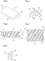
- Le dessin annexé illustre schématiquement et à titre d'exemple une forme d'exécution de l'organe de commande selon l'invention.
- La
figure 1 est une vue en perspective de l'organe de commande d'une pièce d'horlogerie. - La
figure 2 est une vue en perspective du corps de l'organe de commande. - La
figure 3 est une vue en perspective éclatée d'une variante de l'organe de commande. - La
figure 4 est une vue en perspective de la pierre précieuse ou semi-précieuse de l'organe de commande illustré à lafigure 1 . - La
figure 5 est une vue en bout de la pierre illustrée à lafigure 4 . - La
figure 6 est une coupe selon la ligne A-A de lafigure 5 . - La
figure 7 est une vue en coupe selon la ligne C-C de lafigure 6 . - La
figure 8 est un détail de lafigure 7 . - L'organe de commande d'une pièce d'horlogerie illustré à la
figure 1 est une couronne de remontoir, un poussoir ou un verrou formé d'un corps comprenant une tête 1 et une tige de commande 2. La tige de commande 2 est apte à traverser la carrure d'une boîte d'une pièce d'horlogerie et à coopérer avec un mécanisme d'un mouvement horloger placé dans ladite boîte. La tête 1 du corps de l'organe de commande est destinée à être située à l'extérieur de la boîte de la pièce d'horlogerie et apte à être manipulée par un usager. - Dans la forme d'exécution illustrée, la tête 1 du corps de l'organe de commande présente une section droite, perpendiculaire à la tige 2 du corps de l'organe de commande, non circulaire, comportant deux côtés rectilignes parallèles 3, 4 reliés par deux côtés convexes 5, 6. Cette tête 1 présente donc la forme d'un cylindre droit de forme allongée sensiblement rectangulaire présentant deux côtés rectilignes et deux côtés convexes. Dans des variantes, les côtés de la tête de l'organe de commande peuvent avoir d'autres formes incurvées ou non.
- La face frontale 7 de cette tête 1 de l'organe de commande est plane et comporte deux lames 8 s'étendant généralement suivant une direction parallèle à la tige 2 et dont les parois internes se faisant face sont disposées sensiblement le long d'une ligne perpendiculaire aux côtés rectilignes 3, 4 de cette face frontale 7.
- Ces lames 8 sont de préférence venues d'une pièce de fabrication avec la tête 1 de l'organe de commande mais peuvent également y être rapportées ou fixées par soudage, collage ou tout autre moyen.
- La pierre précieuse ou semi-précieuse 9 fixée sur le corps 1, 2 de l'organe de commande présente la forme d'un cabochon, soit d'une tête arrondie qui comporte une base 10 dont la forme et les dimensions correspondent généralement à la surface de la face frontale 7 de la tête 1. Dans la variante illustrée, la tête arrondie n'est pas taillée à facettes, mais dans d'autres variantes elle peut avoir des facettes. Dans la forme d'exécution illustrée, la base 10 a deux côtés rectilignes correspondant aux deux côtés rectilignes 3, 4 de la tête 1 et deux parties droites formées par deux faces terminales 11, 12 de la pierre sur lesquelles sont alignés les flancs internes des lames 8. Ces face terminales 11, 12 sont généralement parallèle l'une à l'autre. Comme la face frontale 7 de la tête 1 de l'organe de commande, la partie inférieure de la base 10 présente elle aussi une surface plane. Lorsque cette pierre 9 est posée sur la face frontale 7 de la tête elle est située entre les côtés rectilignes 3, 4 et les lames 8, les bords latéraux de la pierre en forme de cabochon étant alignés et superposés aux côtés rectilignes 3, 4 de la face frontale 7 de la tête 1.
- Dans l'exemple illustré la face supérieure de la pierre 9 est bombée mais elle peut prendre toute forme désirée.
- Dans l'exemple illustré la base de la pierre est rectangulaire et la distance séparant les deux grands côtés de cette base est sensiblement identique à la distance séparant les deux côtés rectilignes 3, 4 de la tête 1 de l'organe de commande.
- Les faces terminales 11, 12 de la pierre 9 sont usinées par exemple par meulage pour présenter chacune une entaille 11', 12' s'étendant sur une partie de la longueur des faces terminales 11, 12 de la pierre.
- Pour fixer la pierre 9 sur l'organe de commande, on place la pierre 9 sur la face frontale 7 de la tête 1 entre les lames 8 de manière à ce que les bords rectilignes de la base 10 de la pierre 9 soient alignés sur les côtés rectilignes 3, 4 de la tête, et que les faces terminales 11, 12 de la pierre 9 soient situées entre les lames 8, puis on déforme ces lames 8 pour que leurs parties supérieures viennent se placer dans les entailles 11' et 12' de la pierre 9 et sertir de cette manière la pierre 9 sur la tête 1 de l'organe de commande.
- L'organe de commande se distingue donc en ce que sa tête, non circulaire, comporte au moins deux côtés rectilignes sur la face frontale de laquelle une pierre en forme de cabochon présentant une base polygonale dont deux côtés au moins correspondent aux côtés rectilignes de la face frontale de la tête est fixée par sertissage en déformant la partie supérieure de deux lames, solidaires de la face frontale de la tête, dans deux entailles pratiquées dans deux faces terminales de la pierre. Ces entailles 11', 12' sont situées sur les flancs visibles du cabochon.
- Dans une variante illustrée à la
figure 3 , l'organe de commande comporte encore une coiffe 15 fixée par des vis sur la tête 1 de l'organe de commande présentant une cavité dans laquelle est situé le cabochon. Il est à remarquer que les faces terminales 11, 12 du cabochon sont de préférence parallèles l'une à l'autre et que les entailles 11', 12' se trouvent dans la hauteur de la partie frontale du cabochon, généralement dans sa couronne. - Le procédé de sertissage selon l'invention comprend les opérations suivantes :
- 1. On taille une pierre en forme de cabochon de manière à lui conférer une base plane et deux faces terminales comportant chacune une entaille ;
- 2. on configure la tête d'un organe de commande d'une pièce d'horlogerie de manière à lui conférer une face frontale plane munie de deux lames parallèles s'étendant hors de cette face frontale ;
- 3. on place la base de la pierre taillée sur la face frontale plane de la tête de l'organe de commande de manière à ce que les entailles des faces terminales et la pierre soient situées entre les, et en regard des, lames de la face frontale de la tête ; et
- 4. on repousse la partie supérieure des lames dans les entailles de la pierre pour sertir la pierre sur la tête de l'organe de commande.
- Vu en plan, la forme de la pierre en forme de cabochon peut être quelconque pour autant qu'elle présente deux faces terminales opposées munies chacune d'une entaille. De préférence toutefois ce cabochon présente vu en plan une forme polygonale en particulier rectangulaire.
- Ce procédé de sertissage permet la réalisation d'un organe de commande d'une pièce d'horlogerie dont la tête n'est pas circulaire mais présente au moins deux côtés rectilignes. Il présente l'avantage de permettre la réalisation d'un organe de commande d'une pièce d'horlogerie qui vu de dessus présente au moins deux côtés opposés et/ou parallèles qui semblent limités par la pierre précieuse ou semi-précieuse, la tête de l'organe de commande n'étant pas visible le long de ces deux côtés. Ceci est particulièrement avantageux pour un organe de commande non circulaire, par exemple polygonal, de préférence sensiblement rectangulaire.
- De préférence, les deux grands côtés rectilignes de la pierre rectangulaire sont juxtaposés aux côtés rectilignes 3, 4 de la tête 1 de l'organe de commande.
- On obtient ainsi une couronne sertie où une grande partie du cabochon, voire de la couronne du cabochon, est visible sans que la pierre ne sorte du profil de la couronne.
Claims (10)
- Organe de commande d'une pièce d'horlogerie comportant une tête (1) et une tige (2) apte à traverser une boîte de la pièce d'horlogerie et à coopérer avec un mécanisme d'un mouvement de la pièce d'horlogerie, la tête (1) de l'organe de commande présentant une face frontale plane (7), caractérisé en ce que ladite face frontale plane (7) comporte deux lames (8) émergeant de cette face frontale plane (7) s'étendant chacune sensiblement parallèlement à la tige (2) ; et par le fait qu'une pierre (9) précieuse ou semi-précieuse, en forme de cabochon est taillée de sorte à présenter une base plane (10) et deux faces terminales (11, 12) munies chacune d'une entaille (11', 12'), repose par sa base plane (10) sur la face frontale plane (7) de la tête (1) ; cette pierre (9) étant maintenue en place par les parties supérieures des lames (8) qui sont repoussées dans lesdites entailles (11', 12') des faces terminales (11, 12) de la pierre (9).
- Organe de commande selon la revendication 1, caractérisé par le fait que la face frontale (7) de la tête (1) comporte deux côtés opposés rectilignes (3, 4), et en ce que la pierre (9) taillée comporte deux bords parallèles rectilignes recouvrant les deux côtés rectilignes (3, 4) de la tête (1).
- Organe de commande selon la revendication 1, ou la revendication 2, caractérisé par le fait que les lames (8) sont venues d'une pièce de fabrication avec la tête (1) de l'organe de commande.
- Organe de commande selon la revendication 1 ou la revendication 2, caractérisé par le fait que les lames (8) sont rapportées par soudure ou collage sur la face frontale de la tête (1) de l'organe de commande.
- Organe de commande selon l'une des revendications 2 à 4, caractérisé par le fait que vu de dessus la pierre (9) présente une forme sensiblement rectangulaire, les deux côtés rectilignes (3, 4) de la tête étant juxtaposés aux grands côtés de la pierre (9).
- Organe de commande selon l'une des revendications précédentes, caractérisé par le fait que les faces terminales (11,12) sont parallèles entres elles.
- Organe de commande selon l'une des revendications 1 à 6, caractérisé par le fait que les entailles (11', 12') des faces terminales (11,12) du cabochon sont situées dans ces faces terminales à distance de la base (10) du cabochon et se situent sur la périphérie de ce cabochon.
- Procédé de fabrication d'un organe de commande d'une pièce d'horlogerie selon la revendication 1 comportant les opérations suivantes :a. Le taillage d'une pierre précieuse ou semi-précieuse en forme de cabochon de manière à lui conférer une base plane et deux faces terminales comportant chacune une entaille ;b. la configuration d'une tête de l'organe de commande de manière à lui conférer une face frontale plane munie de deux lames parallèles s'étendant hors de cette face frontale ;c. la pose de la base plane de la pierre taillée sur la face frontale plane de la tête de l'organe de commande de manière à ce que les entailles des faces terminales de la pierre soient situées entre les et en regard des lames de la face frontale de la tête ; etd. qu'on repousse la partie supérieure des lames dans les entailles de la pierre pour sertir cette pierre sur la tête de l'organe de commande.
- Procédé selon la revendication 8, caractérisé par le fait que la pierre est taillée de manière à présenter une base rectangulaire, la distance séparant les deux grands côtés de cette base étant égale à celle séparant les côtés rectilignes (3, 4) de la tête de l'organe de commande.
- Procédé selon la revendication 8 ou la revendication 9, caractérisé par le fait que la pierre est taillée de manière à ce que ses entailles soient situées sur la périphérie de cette pierre.
Applications Claiming Priority (2)
| Application Number | Priority Date | Filing Date | Title |
|---|---|---|---|
| CH00043/15A CH710627A1 (fr) | 2015-01-14 | 2015-01-14 | Organe de commande muni d'une pierre précieuse ou semi-précieuse pour une pièce d'horlogerie et son procédé de fabrication. |
| PCT/IB2016/050132 WO2016113674A1 (fr) | 2015-01-14 | 2016-01-13 | Organe de commande d'une piece d'horlogerie et procede de fabrication de celui-ci |
Publications (2)
| Publication Number | Publication Date |
|---|---|
| EP3245564A1 EP3245564A1 (fr) | 2017-11-22 |
| EP3245564B1 true EP3245564B1 (fr) | 2020-03-11 |
Family
ID=52423522
Family Applications (1)
| Application Number | Title | Priority Date | Filing Date |
|---|---|---|---|
| EP16701204.6A Active EP3245564B1 (fr) | 2015-01-14 | 2016-01-13 | Organe de commande d'une piece d'horlogerie et procede de fabrication de celui-ci |
Country Status (4)
| Country | Link |
|---|---|
| EP (1) | EP3245564B1 (fr) |
| CN (1) | CN107209478B (fr) |
| CH (1) | CH710627A1 (fr) |
| WO (1) | WO2016113674A1 (fr) |
Family Cites Families (7)
| Publication number | Priority date | Publication date | Assignee | Title |
|---|---|---|---|---|
| GB161683A (en) * | 1920-01-14 | 1921-04-14 | Bernard Rintel Simmons | A novel or improved spring clip or elastic device adapted to carry or support a watch, coin or coins, brooch, ornament, precious stone or other article or articles |
| CN2075453U (zh) * | 1990-09-08 | 1991-04-24 | 祝强 | 夜光宝石首饰 |
| US5713219A (en) * | 1996-01-18 | 1998-02-03 | Ambar Diamonds, Inc. | Invisible setting for precious stones for jewelry |
| US20020166338A1 (en) * | 2001-05-09 | 2002-11-14 | Jacob Cohen | Oval gemstone arrangements with settings |
| HK1167565A2 (en) * | 2011-01-11 | 2012-11-30 | 赵良贵 | One kind of jade watch |
| CN202133866U (zh) * | 2011-06-09 | 2012-02-01 | 李军 | 装饰玉和宝石的手表 |
| US9402450B2 (en) * | 2012-05-02 | 2016-08-02 | Grand Rainbow International Limited | Invisible setting and methods and tools for effecting same |
-
2015
- 2015-01-14 CH CH00043/15A patent/CH710627A1/fr not_active Application Discontinuation
-
2016
- 2016-01-13 CN CN201680005569.4A patent/CN107209478B/zh active Active
- 2016-01-13 WO PCT/IB2016/050132 patent/WO2016113674A1/fr not_active Ceased
- 2016-01-13 EP EP16701204.6A patent/EP3245564B1/fr active Active
Non-Patent Citations (1)
| Title |
|---|
| None * |
Also Published As
| Publication number | Publication date |
|---|---|
| EP3245564A1 (fr) | 2017-11-22 |
| CH710627A1 (fr) | 2016-07-15 |
| CN107209478B (zh) | 2020-06-30 |
| CN107209478A (zh) | 2017-09-26 |
| WO2016113674A1 (fr) | 2016-07-21 |
Similar Documents
| Publication | Publication Date | Title |
|---|---|---|
| EP3360013B1 (fr) | Boite de montre comportant des cornes amovibles | |
| EP2804055A1 (fr) | Organe régulateur comportant un balancier, un ressort spiral, un piton et un porte-piton et ensemble forme d'un piton et d'un porte-piton | |
| EP3537226B1 (fr) | Procédé de fabrication d'applique diamantée d'horlogerie | |
| EP3099197B1 (fr) | Pierre montée sur un élément ressort | |
| EP4298949B1 (fr) | Bracelet avec maillons en materiau dur | |
| WO2016083680A1 (fr) | Gemme taillee et article comportant une telle gemme | |
| EP3023844B1 (fr) | Virole flexible | |
| EP3596556B1 (fr) | Composant horloger | |
| WO2016113674A1 (fr) | Organe de commande d'une piece d'horlogerie et procede de fabrication de celui-ci | |
| EP3768110B1 (fr) | Piece de joaillerie, procede pour tailler une pierre, en particulier un diamant, et picot de monture associe | |
| EP2677370A1 (fr) | Système antichoc à montage simplifié pour pièce d'horlogerie | |
| EP3037013B1 (fr) | Piece de bijouterie et procede de sertissage de ladite piece de bijouterie | |
| CH709282A2 (fr) | Ancre suspendue pour échappement horloger. | |
| EP3828643A1 (fr) | Cadran pour piece d'horlogerie | |
| EP3432082B1 (fr) | Organe reglant | |
| WO2017060842A1 (fr) | Boite de montre comportant des cornes amovibles | |
| FR2947088A1 (fr) | Inter de presentation pour etre monte sur une surface plane | |
| CH709161A1 (fr) | Pièce de bijouterie à maillons articulés, notamment un bracelet de montre, et son procédé de fabrication. | |
| EP2686135B1 (fr) | Pièce d'habillage pour une pièce d'horlogerie et son système de fabrication | |
| CH719851A2 (fr) | Bracelet avec maillons en matériau dur. | |
| EP4190202A1 (fr) | Chaton de sertissage et procede de sertissage d'un ensemble decoratif | |
| CH719189A2 (fr) | Chaton de sertissage et procédé de sertissage d'un ensemble décoratif. | |
| HK40043683B (en) | Piece of jewellery, method for cutting a stone, in particular a diamond, and associated mounting pin | |
| CH708075A2 (fr) | Système d'assemblage d'au moins trois pièces. | |
| CH706640A2 (fr) | Palier antichoc pour pièce d'horlogerie. |
Legal Events
| Date | Code | Title | Description |
|---|---|---|---|
| STAA | Information on the status of an ep patent application or granted ep patent |
Free format text: STATUS: THE INTERNATIONAL PUBLICATION HAS BEEN MADE |
|
| PUAI | Public reference made under article 153(3) epc to a published international application that has entered the european phase |
Free format text: ORIGINAL CODE: 0009012 |
|
| STAA | Information on the status of an ep patent application or granted ep patent |
Free format text: STATUS: REQUEST FOR EXAMINATION WAS MADE |
|
| 17P | Request for examination filed |
Effective date: 20170627 |
|
| AK | Designated contracting states |
Kind code of ref document: A1 Designated state(s): AL AT BE BG CH CY CZ DE DK EE ES FI FR GB GR HR HU IE IS IT LI LT LU LV MC MK MT NL NO PL PT RO RS SE SI SK SM TR |
|
| AX | Request for extension of the european patent |
Extension state: BA ME |
|
| RIN1 | Information on inventor provided before grant (corrected) |
Inventor name: VUILLEMIN, JEROME Inventor name: BUSSEY, MICHAEL Inventor name: ZANNATO, CHRISTOPHE Inventor name: JONQUET, ROMAIN Inventor name: CASSARD, JEAN-PIERRE Inventor name: PRUDHON, ANTHONY Inventor name: GIRARDIN, DOMINIQUE Inventor name: VIENOT, FLORENT Inventor name: LAMBEY, THOMAS Inventor name: BOYER, LOUIS |
|
| DAV | Request for validation of the european patent (deleted) | ||
| DAX | Request for extension of the european patent (deleted) | ||
| GRAP | Despatch of communication of intention to grant a patent |
Free format text: ORIGINAL CODE: EPIDOSNIGR1 |
|
| STAA | Information on the status of an ep patent application or granted ep patent |
Free format text: STATUS: GRANT OF PATENT IS INTENDED |
|
| INTG | Intention to grant announced |
Effective date: 20191111 |
|
| GRAS | Grant fee paid |
Free format text: ORIGINAL CODE: EPIDOSNIGR3 |
|
| GRAA | (expected) grant |
Free format text: ORIGINAL CODE: 0009210 |
|
| STAA | Information on the status of an ep patent application or granted ep patent |
Free format text: STATUS: THE PATENT HAS BEEN GRANTED |
|
| AK | Designated contracting states |
Kind code of ref document: B1 Designated state(s): AL AT BE BG CH CY CZ DE DK EE ES FI FR GB GR HR HU IE IS IT LI LT LU LV MC MK MT NL NO PL PT RO RS SE SI SK SM TR |
|
| REG | Reference to a national code |
Ref country code: GB Ref legal event code: FG4D Free format text: NOT ENGLISH |
|
| REG | Reference to a national code |
Ref country code: CH Ref legal event code: EP |
|
| REG | Reference to a national code |
Ref country code: AT Ref legal event code: REF Ref document number: 1243927 Country of ref document: AT Kind code of ref document: T Effective date: 20200315 |
|
| REG | Reference to a national code |
Ref country code: IE Ref legal event code: FG4D Free format text: LANGUAGE OF EP DOCUMENT: FRENCH |
|
| REG | Reference to a national code |
Ref country code: DE Ref legal event code: R096 Ref document number: 602016031452 Country of ref document: DE |
|
| REG | Reference to a national code |
Ref country code: CH Ref legal event code: NV Representative=s name: MICHELI AND CIE SA, CH |
|
| PG25 | Lapsed in a contracting state [announced via postgrant information from national office to epo] |
Ref country code: FI Free format text: LAPSE BECAUSE OF FAILURE TO SUBMIT A TRANSLATION OF THE DESCRIPTION OR TO PAY THE FEE WITHIN THE PRESCRIBED TIME-LIMIT Effective date: 20200311 Ref country code: NO Free format text: LAPSE BECAUSE OF FAILURE TO SUBMIT A TRANSLATION OF THE DESCRIPTION OR TO PAY THE FEE WITHIN THE PRESCRIBED TIME-LIMIT Effective date: 20200611 Ref country code: RS Free format text: LAPSE BECAUSE OF FAILURE TO SUBMIT A TRANSLATION OF THE DESCRIPTION OR TO PAY THE FEE WITHIN THE PRESCRIBED TIME-LIMIT Effective date: 20200311 |
|
| REG | Reference to a national code |
Ref country code: NL Ref legal event code: MP Effective date: 20200311 |
|
| PG25 | Lapsed in a contracting state [announced via postgrant information from national office to epo] |
Ref country code: BG Free format text: LAPSE BECAUSE OF FAILURE TO SUBMIT A TRANSLATION OF THE DESCRIPTION OR TO PAY THE FEE WITHIN THE PRESCRIBED TIME-LIMIT Effective date: 20200611 Ref country code: GR Free format text: LAPSE BECAUSE OF FAILURE TO SUBMIT A TRANSLATION OF THE DESCRIPTION OR TO PAY THE FEE WITHIN THE PRESCRIBED TIME-LIMIT Effective date: 20200612 Ref country code: LV Free format text: LAPSE BECAUSE OF FAILURE TO SUBMIT A TRANSLATION OF THE DESCRIPTION OR TO PAY THE FEE WITHIN THE PRESCRIBED TIME-LIMIT Effective date: 20200311 Ref country code: SE Free format text: LAPSE BECAUSE OF FAILURE TO SUBMIT A TRANSLATION OF THE DESCRIPTION OR TO PAY THE FEE WITHIN THE PRESCRIBED TIME-LIMIT Effective date: 20200311 Ref country code: HR Free format text: LAPSE BECAUSE OF FAILURE TO SUBMIT A TRANSLATION OF THE DESCRIPTION OR TO PAY THE FEE WITHIN THE PRESCRIBED TIME-LIMIT Effective date: 20200311 |
|
| REG | Reference to a national code |
Ref country code: LT Ref legal event code: MG4D |
|
| PG25 | Lapsed in a contracting state [announced via postgrant information from national office to epo] |
Ref country code: NL Free format text: LAPSE BECAUSE OF FAILURE TO SUBMIT A TRANSLATION OF THE DESCRIPTION OR TO PAY THE FEE WITHIN THE PRESCRIBED TIME-LIMIT Effective date: 20200311 |
|
| PG25 | Lapsed in a contracting state [announced via postgrant information from national office to epo] |
Ref country code: IS Free format text: LAPSE BECAUSE OF FAILURE TO SUBMIT A TRANSLATION OF THE DESCRIPTION OR TO PAY THE FEE WITHIN THE PRESCRIBED TIME-LIMIT Effective date: 20200711 Ref country code: PT Free format text: LAPSE BECAUSE OF FAILURE TO SUBMIT A TRANSLATION OF THE DESCRIPTION OR TO PAY THE FEE WITHIN THE PRESCRIBED TIME-LIMIT Effective date: 20200805 Ref country code: LT Free format text: LAPSE BECAUSE OF FAILURE TO SUBMIT A TRANSLATION OF THE DESCRIPTION OR TO PAY THE FEE WITHIN THE PRESCRIBED TIME-LIMIT Effective date: 20200311 Ref country code: RO Free format text: LAPSE BECAUSE OF FAILURE TO SUBMIT A TRANSLATION OF THE DESCRIPTION OR TO PAY THE FEE WITHIN THE PRESCRIBED TIME-LIMIT Effective date: 20200311 Ref country code: CZ Free format text: LAPSE BECAUSE OF FAILURE TO SUBMIT A TRANSLATION OF THE DESCRIPTION OR TO PAY THE FEE WITHIN THE PRESCRIBED TIME-LIMIT Effective date: 20200311 Ref country code: SK Free format text: LAPSE BECAUSE OF FAILURE TO SUBMIT A TRANSLATION OF THE DESCRIPTION OR TO PAY THE FEE WITHIN THE PRESCRIBED TIME-LIMIT Effective date: 20200311 Ref country code: EE Free format text: LAPSE BECAUSE OF FAILURE TO SUBMIT A TRANSLATION OF THE DESCRIPTION OR TO PAY THE FEE WITHIN THE PRESCRIBED TIME-LIMIT Effective date: 20200311 Ref country code: SM Free format text: LAPSE BECAUSE OF FAILURE TO SUBMIT A TRANSLATION OF THE DESCRIPTION OR TO PAY THE FEE WITHIN THE PRESCRIBED TIME-LIMIT Effective date: 20200311 |
|
| REG | Reference to a national code |
Ref country code: AT Ref legal event code: MK05 Ref document number: 1243927 Country of ref document: AT Kind code of ref document: T Effective date: 20200311 |
|
| REG | Reference to a national code |
Ref country code: DE Ref legal event code: R097 Ref document number: 602016031452 Country of ref document: DE |
|
| PLBE | No opposition filed within time limit |
Free format text: ORIGINAL CODE: 0009261 |
|
| STAA | Information on the status of an ep patent application or granted ep patent |
Free format text: STATUS: NO OPPOSITION FILED WITHIN TIME LIMIT |
|
| PG25 | Lapsed in a contracting state [announced via postgrant information from national office to epo] |
Ref country code: IT Free format text: LAPSE BECAUSE OF FAILURE TO SUBMIT A TRANSLATION OF THE DESCRIPTION OR TO PAY THE FEE WITHIN THE PRESCRIBED TIME-LIMIT Effective date: 20200311 Ref country code: AT Free format text: LAPSE BECAUSE OF FAILURE TO SUBMIT A TRANSLATION OF THE DESCRIPTION OR TO PAY THE FEE WITHIN THE PRESCRIBED TIME-LIMIT Effective date: 20200311 Ref country code: DK Free format text: LAPSE BECAUSE OF FAILURE TO SUBMIT A TRANSLATION OF THE DESCRIPTION OR TO PAY THE FEE WITHIN THE PRESCRIBED TIME-LIMIT Effective date: 20200311 Ref country code: ES Free format text: LAPSE BECAUSE OF FAILURE TO SUBMIT A TRANSLATION OF THE DESCRIPTION OR TO PAY THE FEE WITHIN THE PRESCRIBED TIME-LIMIT Effective date: 20200311 |
|
| 26N | No opposition filed |
Effective date: 20201214 |
|
| PG25 | Lapsed in a contracting state [announced via postgrant information from national office to epo] |
Ref country code: PL Free format text: LAPSE BECAUSE OF FAILURE TO SUBMIT A TRANSLATION OF THE DESCRIPTION OR TO PAY THE FEE WITHIN THE PRESCRIBED TIME-LIMIT Effective date: 20200311 Ref country code: SI Free format text: LAPSE BECAUSE OF FAILURE TO SUBMIT A TRANSLATION OF THE DESCRIPTION OR TO PAY THE FEE WITHIN THE PRESCRIBED TIME-LIMIT Effective date: 20200311 |
|
| PG25 | Lapsed in a contracting state [announced via postgrant information from national office to epo] |
Ref country code: MC Free format text: LAPSE BECAUSE OF FAILURE TO SUBMIT A TRANSLATION OF THE DESCRIPTION OR TO PAY THE FEE WITHIN THE PRESCRIBED TIME-LIMIT Effective date: 20200311 |
|
| PG25 | Lapsed in a contracting state [announced via postgrant information from national office to epo] |
Ref country code: LU Free format text: LAPSE BECAUSE OF NON-PAYMENT OF DUE FEES Effective date: 20210113 |
|
| REG | Reference to a national code |
Ref country code: BE Ref legal event code: MM Effective date: 20210131 |
|
| PG25 | Lapsed in a contracting state [announced via postgrant information from national office to epo] |
Ref country code: IE Free format text: LAPSE BECAUSE OF NON-PAYMENT OF DUE FEES Effective date: 20210113 |
|
| PG25 | Lapsed in a contracting state [announced via postgrant information from national office to epo] |
Ref country code: BE Free format text: LAPSE BECAUSE OF NON-PAYMENT OF DUE FEES Effective date: 20210131 |
|
| PG25 | Lapsed in a contracting state [announced via postgrant information from national office to epo] |
Ref country code: HU Free format text: LAPSE BECAUSE OF FAILURE TO SUBMIT A TRANSLATION OF THE DESCRIPTION OR TO PAY THE FEE WITHIN THE PRESCRIBED TIME-LIMIT; INVALID AB INITIO Effective date: 20160113 |
|
| PG25 | Lapsed in a contracting state [announced via postgrant information from national office to epo] |
Ref country code: CY Free format text: LAPSE BECAUSE OF FAILURE TO SUBMIT A TRANSLATION OF THE DESCRIPTION OR TO PAY THE FEE WITHIN THE PRESCRIBED TIME-LIMIT Effective date: 20200311 |
|
| PG25 | Lapsed in a contracting state [announced via postgrant information from national office to epo] |
Ref country code: MK Free format text: LAPSE BECAUSE OF FAILURE TO SUBMIT A TRANSLATION OF THE DESCRIPTION OR TO PAY THE FEE WITHIN THE PRESCRIBED TIME-LIMIT Effective date: 20200311 |
|
| PG25 | Lapsed in a contracting state [announced via postgrant information from national office to epo] |
Ref country code: MT Free format text: LAPSE BECAUSE OF FAILURE TO SUBMIT A TRANSLATION OF THE DESCRIPTION OR TO PAY THE FEE WITHIN THE PRESCRIBED TIME-LIMIT Effective date: 20200311 |
|
| REG | Reference to a national code |
Ref country code: DE Ref legal event code: R081 Ref document number: 602016031452 Country of ref document: DE Owner name: RICHEMONT INTERNATIONAL SA, CH Free format text: FORMER OWNER: CARTIER INTERNATIONAL AG, STEINHAUSEN, CH |
|
| PG25 | Lapsed in a contracting state [announced via postgrant information from national office to epo] |
Ref country code: TR Free format text: LAPSE BECAUSE OF FAILURE TO SUBMIT A TRANSLATION OF THE DESCRIPTION OR TO PAY THE FEE WITHIN THE PRESCRIBED TIME-LIMIT Effective date: 20200311 |
|
| REG | Reference to a national code |
Ref country code: CH Ref legal event code: U11 Free format text: ST27 STATUS EVENT CODE: U-0-0-U10-U11 (AS PROVIDED BY THE NATIONAL OFFICE) Effective date: 20260201 |
|
| PGFP | Annual fee paid to national office [announced via postgrant information from national office to epo] |
Ref country code: GB Payment date: 20260123 Year of fee payment: 11 |
|
| PGFP | Annual fee paid to national office [announced via postgrant information from national office to epo] |
Ref country code: DE Payment date: 20260121 Year of fee payment: 11 |
|
| PGFP | Annual fee paid to national office [announced via postgrant information from national office to epo] |
Ref country code: FR Payment date: 20260123 Year of fee payment: 11 |
|
| PGFP | Annual fee paid to national office [announced via postgrant information from national office to epo] |
Ref country code: CH Payment date: 20260201 Year of fee payment: 11 |