EP3245540B1 - Method, system and non-transitory computer-readable medium for forming a seismic image of a geological structure - Google Patents
Method, system and non-transitory computer-readable medium for forming a seismic image of a geological structure Download PDFInfo
- Publication number
- EP3245540B1 EP3245540B1 EP15718367.4A EP15718367A EP3245540B1 EP 3245540 B1 EP3245540 B1 EP 3245540B1 EP 15718367 A EP15718367 A EP 15718367A EP 3245540 B1 EP3245540 B1 EP 3245540B1
- Authority
- EP
- European Patent Office
- Prior art keywords
- seismic wave
- wave data
- region
- geological structure
- predicted
- Prior art date
- Legal status (The legal status is an assumption and is not a legal conclusion. Google has not performed a legal analysis and makes no representation as to the accuracy of the status listed.)
- Active
Links
Images



Classifications
-
- G—PHYSICS
- G01—MEASURING; TESTING
- G01V—GEOPHYSICS; GRAVITATIONAL MEASUREMENTS; DETECTING MASSES OR OBJECTS; TAGS
- G01V1/00—Seismology; Seismic or acoustic prospecting or detecting
- G01V1/28—Processing seismic data, e.g. for interpretation or for event detection
-
- G—PHYSICS
- G01—MEASURING; TESTING
- G01V—GEOPHYSICS; GRAVITATIONAL MEASUREMENTS; DETECTING MASSES OR OBJECTS; TAGS
- G01V2210/00—Details of seismic processing or analysis
- G01V2210/40—Transforming data representation
- G01V2210/43—Spectral
-
- G—PHYSICS
- G01—MEASURING; TESTING
- G01V—GEOPHYSICS; GRAVITATIONAL MEASUREMENTS; DETECTING MASSES OR OBJECTS; TAGS
- G01V2210/00—Details of seismic processing or analysis
- G01V2210/50—Corrections or adjustments related to wave propagation
- G01V2210/57—Trace interpolation or extrapolation, e.g. for virtual receiver; Anti-aliasing for missing receivers
-
- G—PHYSICS
- G01—MEASURING; TESTING
- G01V—GEOPHYSICS; GRAVITATIONAL MEASUREMENTS; DETECTING MASSES OR OBJECTS; TAGS
- G01V2210/00—Details of seismic processing or analysis
- G01V2210/50—Corrections or adjustments related to wave propagation
- G01V2210/58—Media-related
- G01V2210/582—Dispersion
-
- G—PHYSICS
- G01—MEASURING; TESTING
- G01V—GEOPHYSICS; GRAVITATIONAL MEASUREMENTS; DETECTING MASSES OR OBJECTS; TAGS
- G01V2210/00—Details of seismic processing or analysis
- G01V2210/60—Analysis
- G01V2210/67—Wave propagation modeling
- G01V2210/673—Finite-element; Finite-difference
-
- Y—GENERAL TAGGING OF NEW TECHNOLOGICAL DEVELOPMENTS; GENERAL TAGGING OF CROSS-SECTIONAL TECHNOLOGIES SPANNING OVER SEVERAL SECTIONS OF THE IPC; TECHNICAL SUBJECTS COVERED BY FORMER USPC CROSS-REFERENCE ART COLLECTIONS [XRACs] AND DIGESTS
- Y02—TECHNOLOGIES OR APPLICATIONS FOR MITIGATION OR ADAPTATION AGAINST CLIMATE CHANGE
- Y02A—TECHNOLOGIES FOR ADAPTATION TO CLIMATE CHANGE
- Y02A90/00—Technologies having an indirect contribution to adaptation to climate change
- Y02A90/30—Assessment of water resources
Definitions
- the present invention relates to seismic data, and more particularly to a method, system and non-transitory computer-readable medium for forming a seismic image of a geological structure.
- FD dispersion in space could be ameliorated by long stencil method or spectral method.
- the time extrapolation calculated by one side extrapolation of time steps could not be easily implemented by spectral methods, introducing errors that are proportional to the time of propagation, and with phenomena that different frequency components of wavefields propagate with different velocities.
- the high frequency components tend to propagate faster than expected.
- These time dispersion errors might distort the phase and introduce severe artifacts to the data and images, especially for long time propagation.
- the time dispersion might cause mispositioning of reflectors, especially for deep reflectors with high frequency and imaged from long offset data.
- the time dispersion errors may be improved by reducing the time steps used in the FD method, the computational cost dramatically increases.
- US2012/0243371 discloses a system and computer-implemented method for accounting for temporal dispersion in low-order finite difference seismic wave propagation by applying a frequency-domain time varying filter to synthetic data generated by second-order FD modeling, the filter being designed to compensate for temporal dispersion.
- the predicted time dispersion error is
- a system for reducing or eliminating time dispersion errors in predicted seismic wave data, and forming a seismic image of a geological structure using the predicted seismic wave data comprises: a plurality of seismic sensors configured to collect seismic wave data at a first region of the geological structure, the seismic wave data including a plurality of seismic wave traces; and a seismic imaging generating apparatus configured to: receive the seismic wave data at the first region of the geological structure collected by the plurality of seismic sensors, calculate a predicted time dispersion error based on an angular frequency ( ⁇ ) of at least one of the seismic wave traces and a time step ( ⁇ t) to be used in calculating the predicted seismic wave data at a second region of the geological structure using a finite difference approximation, wherein calculating the predicted time dispersion error comprises: estimating a phase shift that results from the use of the finite difference approximation in calculating predicted seismic wave data at the second region (734) of the geological structure, wherein the phase shift is
- the predicted time dispersion error is
- a non-transitory computer-readable medium containing computer executable instructions, which when run on a computer cause it to perform the method according to the first aspect.
- the present invention is directed to reduction and/or elimination of the time dispersion errors such that more accurate seismic image of a geological structure can be formed without sacrificing computational efficiency or increasing computational cost.
- Lu ⁇ 2 ⁇
- ⁇ the Laplacian operator
- ⁇ v ( x ) as the velocity.
- C iJkl the stiffness tensor.
- Lu involves space derivative operator that is assumed to be accurately calculated by the Fourier method.
- Equation (3) X can be an operator as in Equation (2) or it can be a variable. Therefore, F is a functional of the operator or a function of the variable.
- Equation (4) a 2n-order (n is a positive integer) FD scheme is as follows: u t + ⁇ t + u t ⁇ ⁇ t ⁇ 2 u t ⁇ 2 F L n ⁇ t u ,
- Equation (5) The FD schemes for time and space discretization of wave equations can be treated separately, such as the FD in time is an integral for a given 2 nd order time derivative and the FD in space is a regular 1 st order or 2 nd order derivative. Therefore, time dispersion could be considered independently from space dispersion.
- the time dispersion in Equation (5) (i.e., the left hand side of Equation (5)) can be predicted as follows.
- the time dispersion is analyzed and the predicted dispersion is compared with what is calculated by pseudo-spectral method to verify the accuracy of the predicted dispersion that is predicted in accordance with an embodiment of the present invention.
- a simple 1D model is used to demonstrate how the time dispersion is predicted.
- the Fourier transform of u ( l + ⁇ l ) on the left hand side of Equation (5) is e - i ⁇ ⁇ t û ( ⁇ ) if there is no approximation error.
- the phase shift is not exactly ⁇ t. Since the phase shift is related to the frequency and time step, it is assumed to be ⁇ ( ⁇ , ⁇ t).
- Equation (5) Since the space derivatives on the right hand side of Equation (5) are calculated accurately with no numerical errors, the corresponding Fourier transform is not affected. Based on the above analysis, Equation (5) becomes as follows: which implies:
- Equation (8) when the frequency is low and the time step ⁇ t is small enough, ⁇ ( ⁇ , ⁇ t) is close to ⁇ t. Therefore, the time dispersion error is small when the frequency is low and the time step ⁇ t is small. However, the error
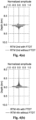
- the relative error ⁇ ⁇ ⁇ t ⁇ ⁇ t ⁇ t for the 2 nd order FD scheme is shown in FIG. 1 .
- FTDT Forward Time Dispersion Transform
- step (3) is a "modified" inverse Fourier transform, in which, instead of using ⁇ t as in an inverse Fourier transform, it has been replaced with the phase shift ⁇ ( ⁇ , ⁇ t). This results in the FTDT predicted trace u ( t ) .
- the 2 nd order and 4 th order FD schemes are used as examples.
- a 1D model with a constant velocity 1500 m/s is used.
- the source is a Ricker wavelet with peak frequency 10 Hz.
- Distance between the source and the receiver is 18 km.
- the blue solid line is the trace calculated by the pseudo-spectral method
- the red dashed line is the trace predicted by the FTDT method
- the green solid line is the analytical solution
- the black dashed line is obtained by applying ITDT on the trace calculated by pseudo-spectral method (blue line).
- the FTDT predicted traces are obtained by applying the FTDT transform on the analytical traces (the green line in FIGs. 2(a) and 2(b) ) which are accurate and have no numerical errors.
- the perfect match between the blue solid line (the pseudo-spectral method) and the red dashed line (the FTDT method) in FIGs. 2(a) and 2(b) shows that the FTDT method accurately predicts the time dispersion for a long propagation time. It is also observed that the modeled wavelet shape is severely distorted because of time dispersion.
- step (2) is a "modified" Fourier transform, in which, instead of using ⁇ t as in Fourier transform, it has been replaced with the phase shift ⁇ ( ⁇ , ⁇ t).
- ITDT is the inverse procedure of FTDT, and it can remove time dispersion errors in the synthetic data.
- the ITDT correction is applied to the traces calculated by the pseudo-spectral method (the blue line in FIGs. 2(a) and 2(b) ), and the result is compared with the analytical solutions (the green line in FIGs. 2(a) and 2(b) ).
- the ITDT corrected traces are shown as the black dashed line in FIGs. 2(a) and 2(b) . It can be observed that the phase distortion is removed after the ITDT correction is applied.
- the fact that the ITDT-corrected traces match perfectly with the analytical solutions for both the 2 nd order and 4 th order schemes shown in FIGs. 2(a) and 2(b) indicates that the ITDT method works well to remove the time dispersion errors in synthetic modeling.
- the time dispersion results using finer time steps are also shown in FIG. 3 .
- the distance between the receiver and the source is 18 km
- ⁇ t 0.5 ms
- the analytical solution green solid line
- the present invention can also be applied to seismic imaging.
- the quality of RTM images is also affected by numerical errors from time dispersion.
- the phase can be distorted, resulting in the shifted depth.
- the FTDT correction can be applied on the data before backward propagation.
- the workflow for RTM imaging can be as follows:
- the FTDT correction on data before backward propagation compensates for the RTM image distortion introduced by forward modeling and backward modeling by phase shifting the seismic wave data at the first region of the geological structure with an amount corresponding to the predicted time dispersion error.
- the entire RTM workflow does not change the computational cost/time too much. The cost of FTDT is negligible compared to the computational time of RTM, thus guaranteeing the efficiency.
- FIGs. 4(a) and 4(b) impulse response tests for both the 2 nd order and 4 th order FD schemes are illustrated in FIGs. 4(a) and 4(b) . These tests are based on the same 1D model used in FIGs. 2(a) and 2(b) .
- the input data is a Ricker wavelet with peak frequency 10 Hz and an impulse at 12s.
- the RTM results for the 2 nd order and 4 th order FD schemes are shown in FIGs. 4(a) and (b) , respectively.
- the FTDT correction is applied on the 3D SEAM (SEG Advanced Modeling Corporation) TTI (tilted transverse isotropy) model.
- 3D SEAM SEG Advanced Modeling Corporation
- TTI tilt transverse isotropy
- the 2 nd order FD time scheme and the TTI equation proposed by Xu and Zhou Xu, S., and H. Zhou, 2014, Accurate simulations of pure quasi-P-waves in complex anisotropic media: Geophysics, 79, no. 6, T341-T348 ) are used for forward and backward propagations.
- a total number of 342 shots shown in FIG. 5 are selected for RTM imaging, and the black lines show the selected 6 shot lines with the 342 shots.
- the same time step ⁇ t 3.032 ms for wave propagation in both cases using 2 nd order FD time scheme.
- the maximum frequency used for migration is 20 Hz. Comparing FIGs. 6(a) and (b) , it can be observed that the events in FIG. 6(b) are much clearer and more focused by using the FTDT correction method.
- FIGs. 6(c) and 6(d) respectively show the enlarged view of the deep part in FIGs. 6(a) and 6(b) , which clearly show that the RTM image generated by applying the FTDT correction on data before backward propagation provides better image quality: 1) better wavelets have been achieved with much less ripple effects (arrows A); 2) the reflector depth has been corrected to the right position (arrow C); and 3) a better focused image has been obtained which is indicated by the improvement of focusing on the image of diffraction points and the unconformity reflector at sediments and base of salt (arrows B).
- arrows B a better focused image has been obtained which is indicated by the improvement of focusing on the image of diffraction points and the unconformity reflector at sediments and base of salt
- time dispersion transform FTDT and its inverse transform ITDT when properly chosen, can remove time dispersion in seismic modeling and imaging.
- the forward transform FTDT can almost perfectly predict the time dispersion in FD modeling, and can be applied to eliminate time dispersion artifacts in RTM images.
- the inverse transform ITDT can be used to remove time dispersion errors in synthetic modeling. These transforms remove time dispersion errors with a negligible cost increase.
- a relatively large time step is also allowed for wave propagation, which significantly increases efficiency while ensuring accuracy.
- the illustrated examples show how the present invention can be applied in seismic modeling and imaging applications, and show the time dispersion can be respectably handled in both isotropic and anisotropic media.
- the present invention can also be used in least-squares RTM and FWI algorithms to improve efficiency and accuracy. This significantly enhances the seismic processing workflow, and generates high quality images of complex subsurface geological structures for oil and gas exploration and any other geological exploration.
- the illustrated embodiments illustrate a method for forming a seismic image of a geological structure, comprising obtaining seismic wave data at a first region of the geological structure, the seismic wave data including a plurality of seismic wave traces; calculating a predicted time dispersion error of an actual time dispersion error that results from a use of a finite difference approximation in calculating predicted seismic wave data at a second region of the geological structure as if a seismic wave propagates from the first region to the second region of the geological structure; compensating each of the seismic wave traces of the seismic wave data at the first region of the geological structure with the predicted time dispersion error, before using the finite difference method to calculate the predicted seismic wave data at the second region of the geological structure; calculating a corrected predicted seismic wave data at the second region of the geological structure by applying the finite difference approximation to the seismic wave data at the first region of the geological structure compensated with the predicted time dispersion error; and generating a seismic image of the second region
- the step of compensating the seismic wave data at the first region of the geological structure with the predicted time dispersion error is performed in a frequency domain.
- the step of calculating the corrected predicted seismic wave data at the second region of the geological structure comprises: transforming the seismic wave data at the first region of the geological structure compensated with the predicted time dispersion error in the frequency domain into a time domain, such that the actual time dispersion error is negated by the predicted time dispersion error in the time domain.
- the step of compensating the seismic wave data at the first region of the geological structure with the predicted time dispersion error comprises: phase shifting the seismic wave data at the first region of the geological structure with an amount corresponding to the predicted time dispersion error, before using the finite difference method to calculate the predicted seismic wave data at the second region of the geological structure.
- the step of phase shifting the seismic wave data at the first region of the geological structure with an amount corresponding to the predicted time dispersion error is performed in a frequency domain.
- the present invention can be implemented in a system 700 for forming a seismic image of a geological structure, which comprises a plurality of seismic sensors 710 configured to collect seismic wave data 720 at a first region 732 of the geological structure, the seismic wave data 720 including a plurality of seismic wave traces; and a seismic imaging generating apparatus 740 configured to: receive the seismic wave data 720 at the first region 732 of the geological structure collected by the plurality of seismic sensors 710, calculate a predicted time dispersion error of an actual time dispersion error that results from a use of a finite difference approximation in calculating predicted seismic wave data at a second region 734 of the geological structure as if a seismic wave propagates from the first region 732 to the second region 734 of the geological structure, compensate each of the seismic wave traces of the seismic wave data at the first region of the geological structure with the predicted time dispersion error, before using the finite difference method to calculate the predicted seismic wave data
- the seismic imaging generating apparatus 740 can be realized in digital electronic circuitry or hardware, including a programmable processor, a computer, a server, or multiple processors, computers or servers and their structural equivalents, or in combinations of one or more of them.
- the present invention can be implemented as one or more computer program products, i.e., one or more modules of computer program instructions encoded on a non-transitory computer readable medium for execution by, or to control the operation of, data processing apparatus.
- the computer readable medium can be a machine-readable storage device, a machine-readable storage substrate, a memory device, a composition of matter effecting a machine-readable propagated signal, or a combination of one or more of them.
Landscapes
- Engineering & Computer Science (AREA)
- Remote Sensing (AREA)
- Physics & Mathematics (AREA)
- Life Sciences & Earth Sciences (AREA)
- Acoustics & Sound (AREA)
- Environmental & Geological Engineering (AREA)
- Geology (AREA)
- General Life Sciences & Earth Sciences (AREA)
- General Physics & Mathematics (AREA)
- Geophysics (AREA)
- Geophysics And Detection Of Objects (AREA)
Description
- The present invention relates to seismic data, and more particularly to a method, system and non-transitory computer-readable medium for forming a seismic image of a geological structure.
- The research of seismic imaging on complex geological structures currently focuses on the development of algorithms that are based on two-way wave equations, such as reverse-time migration (RTM) and full-waveform inversion (FWI). However, the wave propagation has dominated the computational time/cost for seismic imaging on complex geological structures, and the accuracy and efficiency of wave propagation are crucial to the success of real applications of these algorithms. One commonly used method to calculate wave field is the finite difference (FD) method.
- To improve the efficiency of wave propagation calculation, conventional ways tend to use large sampling rate of discretization. However, numerical dispersion due to discretization of time and space derivatives can introduce severe numerical errors in synthetic data and migrated images, especially when the sampling rate is large. Therefore, reduction of numerical dispersion has become important for efficient and accurate wave propagation algorithms.
- FD dispersion in space could be ameliorated by long stencil method or spectral method. However, the time extrapolation calculated by one side extrapolation of time steps could not be easily implemented by spectral methods, introducing errors that are proportional to the time of propagation, and with phenomena that different frequency components of wavefields propagate with different velocities. For example, for the conventional 2nd order FD time scheme, it appears that the high frequency components tend to propagate faster than expected. These time dispersion errors might distort the phase and introduce severe artifacts to the data and images, especially for long time propagation. For seismic imaging, the time dispersion might cause mispositioning of reflectors, especially for deep reflectors with high frequency and imaged from long offset data. Although the time dispersion errors may be improved by reducing the time steps used in the FD method, the computational cost dramatically increases.
-
US2012/0243371 discloses a system and computer-implemented method for accounting for temporal dispersion in low-order finite difference seismic wave propagation by applying a frequency-domain time varying filter to synthetic data generated by second-order FD modeling, the filter being designed to compensate for temporal dispersion. - Accordingly, it is an object of the present invention to provide a method, system and non-transitory computer-readable medium for forming a seismic image of a geological structure that can reduce and/or eliminate the FD time dispersion errors at marginal computational cost.
- To achieve the above-mentioned object, according to a first aspect of the present invention, a method for reducing or eliminating time dispersion errors in predicted seismic wave 35599382-1 data, and forming a seismic image of a geological structure using the predicted seismic wave data, the method comprises: obtaining seismic wave data at a first region of the geological structure, the seismic wave data including a plurality of seismic wave traces; calculating a predicted time dispersion error based on an angular frequency (ω) of at least one of the seismic wave traces and a time step (Δt) to be used in calculating the predicted seismic wave data at a second region of the geological structure using a finite difference approximation, wherein calculating the predicted time dispersion error comprises: estimating a phase shift that results from the use of the finite difference approximation in calculating predicted seismic wave data at the second region (734) of the geological structure, wherein the phase shift is θ(ω, Δt) = sgn(ω)·acos(1 + F(-ω 2, n, Δt)), where ω is the angular frequency of the seismic wave trace, Δt is the time step of the finite difference approximation, 2n is an order of the finite difference approximation, and n is a positive integer, and

- According to a second aspect of the present invention, a system for reducing or eliminating time dispersion errors in predicted seismic wave data, and forming a seismic image of a geological structure using the predicted seismic wave data comprises: a plurality of seismic sensors configured to collect seismic wave data at a first region of the geological structure, the seismic wave data including a plurality of seismic wave traces; and a seismic imaging generating apparatus configured to: receive the seismic wave data at the first region of the geological structure collected by the plurality of seismic sensors, calculate a predicted time dispersion error based on an angular frequency (ω) of at least one of the seismic wave traces and a time step (Δt) to be used in calculating the predicted seismic wave data at a second region of the geological structure using a finite difference approximation, wherein calculating the predicted time dispersion error comprises: estimating a phase shift that results from the use of the finite difference approximation in calculating predicted seismic wave data at the second region (734) of the geological structure, wherein the phase shift is θ(ω, Δt) = sgn(ω) · acos(1 + F(-ω 2, n, Δt)), where ω is the angular frequency of the seismic wave trace, Δt is the time step of the finite difference approximation, 2n is an order of the finite difference approximation, and n is a positive integer, and

- According to a third aspect of the present invention, a non-transitory computer-readable medium containing computer executable instructions, which when run on a computer cause it to perform the method according to the first aspect.
- Further scope of applicability of the present invention will become apparent from the detailed description given hereinafter. However, it should be understood that the detailed description and specific examples, while indicating preferred embodiments of the invention, are given by way of illustration only, the scope of the invention being solely defined by the appended claims.
- The present invention will become more fully understood from the detailed description given hereinbelow and the accompanying drawings which are given by way of illustration only, and thus are not limitative of the present invention, and wherein:
-
FIG. 1(a) shows a relative error
-
FIG. 1(b) shows a relative error
-
FIG. 2(a) shows a 1D modeling example in the 2nd order FD scheme in accordance with an embodiment of the present invention; -
FIG. 2(b) shows a 1D modeling example in the 4th order FD scheme in accordance with an embodiment of the present invention; -
FIG. 3 shows a fine time step example calculated by the pseudo-spectral method in the 2nd order scheme; -
FIG. 4(a) shows a 1D RTM example with and without applying the FTDT correction on data in the 2nd order FD scheme; -
FIG. 4(b) shows a 1D RTM example with and without applying the FTDT correction on data in the 4th order FD scheme; -
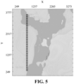
FIG. 5 shows shots used in a 3D SEAM TTI example; -
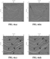
FIG. 6(a) shows an RTM image generated by the conventional RTM; -
FIG. 6(b) shows an RTM image generated by applying the FTDT correction on data before back propagation in accordance with an embodiment of the present invention; -
FIG. 6(c) shows an enlarged view of the deep part inFIGs. 6(a) ; and -
FIG. 6(d) shows an enlarged view of the deep part inFIGs. 6(b) . -
FIG. 7 shows a system for forming a seismic image of a geological structure in accordance with an embodiment of the present invention. - The present invention will now be described in detail with reference to the accompanying drawings, wherein the same reference numerals will be used to identify the same or similar elements throughout the several views. It should be noted that the drawings should be viewed in the direction of orientation of the reference numerals.
- The present invention is directed to reduction and/or elimination of the time dispersion errors such that more accurate seismic image of a geological structure can be formed without sacrificing computational efficiency or increasing computational cost.
- In order to effectively reduce or eliminate the time dispersion errors, an investigation of the time dispersion problem is necessary. The investigation starts with a general wave equation. With absence of source term, the propagation can be described by Equation (1) as follows:

where - u = u(
x ,t) is the wavefield, which may represent pressure for an acoustic case or displacement vector for an elastic case, - t is time, and
- L is a space differential operator.
- In acoustic case, Lu = ν 2Δ, with Δ as the Laplacian operator

x ) as the velocity. In elastic case,
- The term Lu involves space derivative operator that is assumed to be accurately calculated by the Fourier method. With respect to the time dispersion and its corrections, based on Taylor expansion, a general time scheme can be obtained by the following Equation (2)

where - Δt is the time step, and
- the mapping F is defined as

- In Equation (3), X can be an operator as in Equation (2) or it can be a variable. Therefore, F is a functional of the operator or a function of the variable. In Equation (2), the time derivative terms on the right hand side are computed by space derivatives as follows

- In practice, only a limited number of terms is used on the right hand side of Equation (4). For example, a 2n-order (n is a positive integer) FD scheme is as follows:

- It should be noted that the symbol "≅" is used in Equation (5), because Equation (5) is just an approximation instead of the exact equality relation. If n = 1, Equation (5) is the 2nd order FD scheme. If n = 2, Equation (5) is the 4th order FD scheme.
- As can been seen in Equation (5), The FD schemes for time and space discretization of wave equations can be treated separately, such as the FD in time is an integral for a given 2nd order time derivative and the FD in space is a regular 1st order or 2nd order derivative. Therefore, time dispersion could be considered independently from space dispersion.
- The time dispersion in Equation (5) (i.e., the left hand side of Equation (5)) can be predicted as follows. The time dispersion is analyzed and the predicted dispersion is compared with what is calculated by pseudo-spectral method to verify the accuracy of the predicted dispersion that is predicted in accordance with an embodiment of the present invention. In this illustrated example, a simple 1D model is used to demonstrate how the time dispersion is predicted.
- To analyze the time dispersion, a time Fourier transform û(ω) = ∫u(t)eiωtdt is applied to Equation (5). In theory, the Fourier transform of u(l + Δl) on the left hand side of Equation (5) is e -iωΔ tû(ω) if there is no approximation error. However, because of time dispersion from FD approximation, the phase shift is not exactly ωΔt. Since the phase shift is related to the frequency and time step, it is assumed to be θ (ω, Δt). Then the corresponding transform of u(t + Δt) is e-iθ(ω,νt) û(ω) is made. Similarly, the transform of u(t - Δt) is e iθ(ω,Δt) û(ω). Since the space derivatives on the right hand side of Equation (5) are calculated accurately with no numerical errors, the corresponding Fourier transform is not affected. Based on the above analysis, Equation (5) becomes as follows:


- As a result, Equation (8) is obtained as follows:

- According to Equation (8), when the frequency is low and the time step Δt is small enough, θ (ω, Δt) is close to ωΔt. Therefore, the time dispersion error is small when the frequency is low and the time step Δt is small. However, the error |θ(ω, Δt) - ωΔt| increases with the time step and frequency. The relative error

FIG. 1 . - To predict the time dispersion from the FD schemes, a "Forward Time Dispersion Transform" (FTDT) is proposed here, which should be implemented for every single time trace u(t) which has no time dispersion errors, as described in the following steps:
- (1) Calculate θ(ω, Δt) by Equation (8) for valid frequencies;
- (2) Apply Fourier Transform to the trace: û(ω) = ∫u(t)eiωtdt to transform the trace into the frequency domain;
- (3) Apply inverse "modified" Fourier transform to obtain the predicted trace in the time domain:
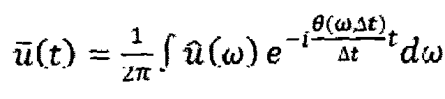
- It should be noted that step (3) is a "modified" inverse Fourier transform, in which, instead of using ωΔt as in an inverse Fourier transform, it has been replaced with the phase shift θ(ω, Δt). This results in the FTDT predicted trace
u (t). - To verify the accuracy of the FTDT prediction, the 2nd order and 4th order FD schemes are used as examples. In the illustrated examples shown in
FIGs. 2(a) and 2(b) , a 1D model with a constant velocity 1500 m/s is used. The source is a Ricker wavelet withpeak frequency 10 Hz. Distance between the source and the receiver is 18 km. The blue solid line is the trace calculated by the pseudo-spectral method, the red dashed line is the trace predicted by the FTDT method, the green solid line is the analytical solution, and the black dashed line is obtained by applying ITDT on the trace calculated by pseudo-spectral method (blue line). - In order to verify the prediction capability of the FTDT method, the comparison between the FTDT predicted traces and those calculated by the pseudo-spectral method are illustrated. The FTDT predicted traces are obtained by applying the FTDT transform on the analytical traces (the green line in
FIGs. 2(a) and 2(b) ) which are accurate and have no numerical errors. The time steps are Δt = 3 ms in the 2nd order modeling and Δt = 9 ms in the 4th order modeling. In the illustrated examples, the perfect match between the blue solid line (the pseudo-spectral method) and the red dashed line (the FTDT method) inFIGs. 2(a) and 2(b) shows that the FTDT method accurately predicts the time dispersion for a long propagation time. It is also observed that the modeled wavelet shape is severely distorted because of time dispersion. - In view of the above, it is clear that the time dispersion is predicted accurately by the proposed FTDT method. Since the time dispersion has been accurately predicted, a "modified" inverse Fourier transform can be used to compensate for the time dispersion. In order to eliminate the time dispersion, an "Inverse Time Dispersion Transform" (ITDT) is applied to every single modeled trace as follows:
- (1) Calculate θ(ω, Δt) by Equation (8) for valid frequencies;
- (2) Apply a "modified" Fourier transform:

- (3) Apply inverse Fourier transform:
u (t) = ∫û'(ω)e -i ωtdω to obtain the ITDT corrected traceu '(t) in the time domain. - It should be noted that step (2) is a "modified" Fourier transform, in which, instead of using ωΔt as in Fourier transform, it has been replaced with the phase shift θ (ω, Δt).
- In particular, ITDT is the inverse procedure of FTDT, and it can remove time dispersion errors in the synthetic data. To verify its effectiveness, the ITDT correction is applied to the traces calculated by the pseudo-spectral method (the blue line in
FIGs. 2(a) and 2(b) ), and the result is compared with the analytical solutions (the green line inFIGs. 2(a) and 2(b) ). The ITDT corrected traces are shown as the black dashed line inFIGs. 2(a) and 2(b) . It can be observed that the phase distortion is removed after the ITDT correction is applied. The fact that the ITDT-corrected traces match perfectly with the analytical solutions for both the 2nd order and 4th order schemes shown inFIGs. 2(a) and 2(b) indicates that the ITDT method works well to remove the time dispersion errors in synthetic modeling. - For comparison purposes, the time dispersion results using finer time steps are also shown in
FIG. 3 . In this example, the distance between the receiver and the source is 18 km, and the 2nd order scheme calculated by the pseudo-spectral method is illustrated, showing the modeled trace (black dashed line) using a time step Δt = 0.5 ms and its comparison with the analytical solution (green solid line). Although using a very fine time step, with five times more computational cost than using a time step Δt = 3 ms, some numerical errors still exist in the trace modeled by the pseudo-spectral method (the black dashed line inFIG. 3 ). On the other hand, when the ITDT method is used, larger time steps can be used and computational time is dramatically reduced, while the time dispersion errors are effectively removed, as shown inFIG. 2(a) . This clearly shows the superiority of the ITDT correction method for synthetic modeling. - Similar to seismic modeling, the present invention can also be applied to seismic imaging. For example, the quality of RTM images is also affected by numerical errors from time dispersion. The phase can be distorted, resulting in the shifted depth. To eliminate the time dispersion errors in RTM imaging, the FTDT correction can be applied on the data before backward propagation. In an embodiment of the present invention, the workflow for RTM imaging can be as follows:
- (1) Forward propagation to calculate forward seismic wave data at the second region of the geological structure;
- (2) Apply FTDT on the seismic wave data before backward propagation to compensate each of the seismic wave traces of the seismic wave data at the first region of the geological structure with a predicted time dispersion error;
- (3) Backward propagation to calculate a corrected predicted backward seismic wave data at the second region of the geological structure by applying the finite difference approximation to the seismic wave data at the first region of the geological structure compensated with the predicted time dispersion error; and
- (4) Apply imaging condition to generate a seismic image of the second region of the geological structure using the corrected predicted seismic wave data, such that the actual time dispersion error is negated by the predicted time dispersion error.
- In particular, the FTDT correction on data before backward propagation compensates for the RTM image distortion introduced by forward modeling and backward modeling by phase shifting the seismic wave data at the first region of the geological structure with an amount corresponding to the predicted time dispersion error. In addition, the entire RTM workflow does not change the computational cost/time too much. The cost of FTDT is negligible compared to the computational time of RTM, thus guaranteeing the efficiency.
- To demonstrate the effectiveness of the present invention for RTM imaging, impulse response tests for both the 2nd order and 4th order FD schemes are illustrated in
FIGs. 4(a) and 4(b) . These tests are based on the same 1D model used inFIGs. 2(a) and 2(b) . The input data is a Ricker wavelet withpeak frequency 10 Hz and an impulse at 12s. The RTM results for the 2nd order and 4th order FD schemes are shown inFIGs. 4(a) and (b) , respectively. The time steps are Δt = 3 ms for the 2nd order scheme and Δt = 9 ms for the 4th order scheme. The comparisons between the RTM responses with and without the FTDT correction show that the severe phase distortion is removed and the depth becomes accurate by applying the FTDT correction method. Except for a little computational time spent on applying FTDT to the input data, this approach does not increase memory cost or any further computational cost. This allows the use of large time steps for imaging, which significantly improves efficiency. - In this example, the FTDT correction is applied on the 3D SEAM (SEG Advanced Modeling Corporation) TTI (tilted transverse isotropy) model. In particular, the 2nd order FD time scheme and the TTI equation proposed by Xu and Zhou ( Xu, S., and H. Zhou, 2014, Accurate simulations of pure quasi-P-waves in complex anisotropic media: Geophysics, 79, no. 6, T341-T348 ) are used for forward and backward propagations. A total number of 342 shots shown in
FIG. 5 are selected for RTM imaging, and the black lines show the selected 6 shot lines with the 342 shots. - The RTM image (at X = 8360 m) generated by the conventional RTM is shown in
FIG. 6(a) , while the RTM image (at X = 8360 m) generated by applying the FTDT correction on data before backward propagation is shown inFIG. 6(b) . In addition, the same time step Δt = 3.032 ms for wave propagation in both cases using 2nd order FD time scheme. The maximum frequency used for migration is 20 Hz. ComparingFIGs. 6(a) and(b) , it can be observed that the events inFIG. 6(b) are much clearer and more focused by using the FTDT correction method. The depth of the events, especially for the deep events, is also corrected to the right position by applying the FTDT correction on data before backward propagation.FIGs. 6(c) and 6(d) respectively show the enlarged view of the deep part inFIGs. 6(a) and 6(b) , which clearly show that the RTM image generated by applying the FTDT correction on data before backward propagation provides better image quality: 1) better wavelets have been achieved with much less ripple effects (arrows A); 2) the reflector depth has been corrected to the right position (arrow C); and 3) a better focused image has been obtained which is indicated by the improvement of focusing on the image of diffraction points and the unconformity reflector at sediments and base of salt (arrows B). These illustrated examples clearly indicate that the FTDT correction method works well in complex 3D imaging and in both isotropic media and anisotropic media. - In view of the above, it is clear that the time dispersion transform FTDT and its inverse transform ITDT, when properly chosen, can remove time dispersion in seismic modeling and imaging. The forward transform FTDT can almost perfectly predict the time dispersion in FD modeling, and can be applied to eliminate time dispersion artifacts in RTM images. The inverse transform ITDT can be used to remove time dispersion errors in synthetic modeling. These transforms remove time dispersion errors with a negligible cost increase. In addition, a relatively large time step is also allowed for wave propagation, which significantly increases efficiency while ensuring accuracy.
- The illustrated examples show how the present invention can be applied in seismic modeling and imaging applications, and show the time dispersion can be respectably handled in both isotropic and anisotropic media. The present invention can also be used in least-squares RTM and FWI algorithms to improve efficiency and accuracy. This significantly enhances the seismic processing workflow, and generates high quality images of complex subsurface geological structures for oil and gas exploration and any other geological exploration.
- In view of the above, the illustrated embodiments illustrate a method for forming a seismic image of a geological structure, comprising obtaining seismic wave data at a first region of the geological structure, the seismic wave data including a plurality of seismic wave traces; calculating a predicted time dispersion error of an actual time dispersion error that results from a use of a finite difference approximation in calculating predicted seismic wave data at a second region of the geological structure as if a seismic wave propagates from the first region to the second region of the geological structure; compensating each of the seismic wave traces of the seismic wave data at the first region of the geological structure with the predicted time dispersion error, before using the finite difference method to calculate the predicted seismic wave data at the second region of the geological structure; calculating a corrected predicted seismic wave data at the second region of the geological structure by applying the finite difference approximation to the seismic wave data at the first region of the geological structure compensated with the predicted time dispersion error; and generating a seismic image of the second region of the geological structure using the corrected predicted seismic wave data, such that the actual time dispersion error is negated by the predicted time dispersion error.
- According to the present invention, the step of calculating the predicted time dispersion error comprises: estimating a phase shift that results from the use of the finite difference approximation in calculating predicted seismic wave data at the second region of the geological structure, wherein the phase shift is θ(ω, Δt) = sgn(ω) · acos(1 + F(-ω 2 , n, Δt)), where
- ω is an angular frequency of the seismic wave trace,
- Δt is a time step of the finite difference approximation,
- 2n is an order of the finite difference approximation, and n is a positive integer, and

- wherein the predicted time dispersion error is |θ(ω,Δt) ωΔt|.
- In an embodiment of the present invention, the step of compensating the seismic wave data at the first region of the geological structure with the predicted time dispersion error is performed in a frequency domain.
- In an embodiment of the present invention, the step of calculating the corrected predicted seismic wave data at the second region of the geological structure comprises: transforming the seismic wave data at the first region of the geological structure compensated with the predicted time dispersion error in the frequency domain into a time domain, such that the actual time dispersion error is negated by the predicted time dispersion error in the time domain.
- In an embodiment of the present invention, the step of compensating the seismic wave data at the first region of the geological structure with the predicted time dispersion error comprises: phase shifting the seismic wave data at the first region of the geological structure with an amount corresponding to the predicted time dispersion error, before using the finite difference method to calculate the predicted seismic wave data at the second region of the geological structure.
- In an embodiment of the present invention, the step of phase shifting the seismic wave data at the first region of the geological structure with an amount corresponding to the predicted time dispersion error is performed in a frequency domain.
- In addition, as shown in
FIG. 7 , in one embodiment, the present invention can be implemented in a system 700 for forming a seismic image of a geological structure, which comprises a plurality of seismic sensors 710 configured to collect seismic wave data 720 at a first region 732 of the geological structure, the seismic wave data 720 including a plurality of seismic wave traces; and a seismic imaging generating apparatus 740 configured to: receive the seismic wave data 720 at the first region 732 of the geological structure collected by the plurality of seismic sensors 710, calculate a predicted time dispersion error of an actual time dispersion error that results from a use of a finite difference approximation in calculating predicted seismic wave data at a second region 734 of the geological structure as if a seismic wave propagates from the first region 732 to the second region 734 of the geological structure, compensate each of the seismic wave traces of the seismic wave data at the first region of the geological structure with the predicted time dispersion error, before using the finite difference method to calculate the predicted seismic wave data at the second region of the geological structure, calculate a corrected predicted seismic wave data at the second region of the geological structure by applying the finite difference approximation to the seismic wave data at the first region of the geological structure compensated with the predicted time dispersion error, and generate a seismic image of the second region of the geological structure using the corrected predicted seismic wave data, such that the actual time dispersion error is negated by the predicted time dispersion error. - In an embodiment of the present invention, the seismic
imaging generating apparatus 740 can be realized in digital electronic circuitry or hardware, including a programmable processor, a computer, a server, or multiple processors, computers or servers and their structural equivalents, or in combinations of one or more of them. - In another embodiment, the present invention can be implemented as one or more computer program products, i.e., one or more modules of computer program instructions encoded on a non-transitory computer readable medium for execution by, or to control the operation of, data processing apparatus. The computer readable medium can be a machine-readable storage device, a machine-readable storage substrate, a memory device, a composition of matter effecting a machine-readable propagated signal, or a combination of one or more of them.
- The invention being thus described, it will be obvious that the same may be varied in many ways, the scope of the invention being solely defined by the appended claims.
Claims (10)
- A method for reducing or eliminating time dispersion errors in predicted seismic wave data, and forming a seismic image of a geological structure using the predicted seismic wave data, the method comprising:obtaining seismic wave data (720) at a first region (732) of the geological structure, the seismic wave data including a plurality of seismic wave traces;calculating a predicted time dispersion error based on an angular frequency (ω) of at least one of the seismic wave traces and a time step (Δt) to be used in calculating the predicted seismic wave data at a second region (734) of the geological structure using a finite difference approximation, wherein calculating the predicted time dispersion error comprises:
estimating a phase shift that results from the use of the finite difference approximation in calculating predicted seismic wave data at the second region (734) of the geological structure,wherein the phase shift is ω is the angular frequency of the seismic wave trace,Δt is the time step of the finite difference approximation,2n is an order of the finite difference approximation, and n is a positive integer, and
 wherein the predicted time dispersion error is |θ(ω),Δt) - ωΔt|;compensating each of the seismic wave traces of the seismic wave data (720) at the first region (732) of the geological structure with the predicted time dispersion error;after compensating each of the seismic wave traces, calculating the predicted seismic wave data at the second region (734) of the geological structure by applying the finite difference approximation to the seismic wave data at the first region of the geological structure compensated with the predicted time dispersion error; andgenerating a seismic image of the second region (734) of the geological structure using the predicted seismic wave data.
 - The method of claim 1, wherein the step of compensating the seismic wave data (720) at the first region (732) of the geological structure with the predicted time dispersion error is performed in a frequency domain.
- The method of claim 1 or 2, wherein the step of calculating the predicted seismic wave data at the second region (734) of the geological structure comprises:
transforming the seismic wave data at the first region (732) of the geological structure compensated with the predicted time dispersion error in the frequency domain into a time domain. - The method of any one of claims 1 to 3, wherein the step of compensating the seismic wave data (720) at the first region (732) of the geological structure with the predicted time dispersion error comprises:phase shifting the seismic wave data at the first region (732) of the geological structure with an amount corresponding to the predicted time dispersion error, before using the finite difference method to calculate the predicted seismic wave data at the second region (734) of the geological structure,optionally the step of phase shifting the seismic wave data at the first region (732) of the geological structure with an amount corresponding to the predicted time dispersion error is performed in a frequency domain.
- A system (700) for reducing or eliminating time dispersion errors in predicted seismic wave data, and forming a seismic image of a geological structure using the predicted seismic wave data, comprising:a plurality of seismic sensors (710) configured to collect seismic wave data (720) at a first region (732) of the geological structure, the seismic wave data (720) including a plurality of seismic wave traces; anda seismic imaging generating apparatus configured to:receive the seismic wave data (720) at the first region (732) of the geological structure collected by the plurality of seismic sensors (710),calculate a predicted time dispersion error based on an angular frequency (ω) of at least one of the seismic wave traces and a time step (Δt) to be used in calculating the predicted seismic wave data at a second region (734) of the geological structure using a finite difference approximation, wherein calculating the predicted time dispersion error comprises:estimating a phase shift that results from the use of the finite difference approximation in calculating predicted seismic wave data at the second region (734) of the geological structure,wherein the phase shift is
 ω is the angular frequency of the seismic wave trace,Δt is the time step of the finite difference approximation,2n is an order of the finite difference approximation, and n is a positive integer, and
 wherein the predicted time dispersion error is |θ(ω,Δt) - ωΔt|;compensate each of the seismic wave traces of the seismic wave data (720) at the first region (732) of the geological structure with the predicted time dispersion error,after compensating each of the seismic wave traces, calculate the predicted seismic wave data at the second region (734) of the geological structure by applying the finite difference approximation to the seismic wave data at the first region (732) of the geological structure compensated with the predicted time dispersion error, andgenerate a seismic image of the second region (734) of the geological structure using the predicted seismic wave data.
 - The system of claim 5, wherein the seismic imaging generating apparatus is configured to compensate the seismic wave data at the first region (732) of the geological structure with the predicted time dispersion error in a frequency domain.
- The system of claim 5 or 6, wherein the seismic imaging generating apparatus is configured to calculate the predicted seismic wave data at the second region (734) of the geological structure by transforming the seismic wave data at the first region (732) of the geological structure compensated with the predicted time dispersion error in the frequency domain into a time domain.
- The system of any one of claims 5 to 7, wherein the seismic imaging generating apparatus is configured to compensate the seismic wave data (720) at the first region (732) of the geological structure with the predicted time dispersion error by phase shifting the seismic wave data at the first region of the geological structure with an amount corresponding to the predicted time dispersion error, before using the finite difference method to calculate the predicted seismic wave data at the second region (734) of the geological structure.
- The system of claim 8, wherein the seismic imaging generating apparatus is configured to phase shift the seismic wave data at the first region (732) of the geological structure with an amount corresponding to the predicted time dispersion error in a frequency domain.
- A non-transitory computer-readable medium containing computer executable instructions, which when run on a computer cause it to perform the method according to any one of claims 1 to 4.
Applications Claiming Priority (2)
| Application Number | Priority Date | Filing Date | Title |
|---|---|---|---|
| CN2015070655 | 2015-01-14 | ||
| PCT/EP2015/059139 WO2016112997A1 (en) | 2015-01-14 | 2015-04-28 | Method, system and non-transitory computer-readable medium for forming a seismic image of a geological structure |
Publications (2)
| Publication Number | Publication Date |
|---|---|
| EP3245540A1 EP3245540A1 (en) | 2017-11-22 |
| EP3245540B1 true EP3245540B1 (en) | 2023-11-08 |
Family
ID=56405268
Family Applications (1)
| Application Number | Title | Priority Date | Filing Date |
|---|---|---|---|
| EP15718367.4A Active EP3245540B1 (en) | 2015-01-14 | 2015-04-28 | Method, system and non-transitory computer-readable medium for forming a seismic image of a geological structure |
Country Status (9)
| Country | Link |
|---|---|
| US (1) | US10690791B2 (en) |
| EP (1) | EP3245540B1 (en) |
| CN (1) | CN107407737B (en) |
| AU (1) | AU2015377943B2 (en) |
| BR (1) | BR112017015075B1 (en) |
| CA (1) | CA2973278C (en) |
| EA (1) | EA036891B1 (en) |
| MX (1) | MX386247B (en) |
| WO (1) | WO2016112997A1 (en) |
Families Citing this family (2)
| Publication number | Priority date | Publication date | Assignee | Title |
|---|---|---|---|---|
| US11275190B2 (en) * | 2018-05-16 | 2022-03-15 | Saudi Arabian Oil Company | Generating diffraction images based on wave equations |
| CN113391353B (en) * | 2020-03-11 | 2024-06-25 | 中国石油天然气集团有限公司 | Seismic data processing method and device |
Family Cites Families (14)
| Publication number | Priority date | Publication date | Assignee | Title |
|---|---|---|---|---|
| US6687617B2 (en) * | 2001-06-28 | 2004-02-03 | Pgs America, Inc. | Method and system for migration of seismic data |
| US7219032B2 (en) * | 2002-04-20 | 2007-05-15 | John Louis Spiesberger | Estimation algorithms and location techniques |
| US6865489B2 (en) * | 2002-10-02 | 2005-03-08 | Exxonmobil Upstream Research Company | Method for compensating mild lateral velocity variations in pre-stack time migration in the frequency-wave number domain |
| US6819628B2 (en) * | 2003-04-07 | 2004-11-16 | Paradigm Geophysical (Luxembourg) S.A.R.L. | Wave migration by a krylov space expansion of the square root exponent operator, for use in seismic imaging |
| US8121792B2 (en) * | 2008-03-31 | 2012-02-21 | Exxonmobil Upstream Research Co. | Integration of geomechanics and seismic analysis for passive seismic feasibility analysis |
| US9864082B2 (en) * | 2008-11-06 | 2018-01-09 | Pgs Geophysical As | Fourier finite-difference migration for three dimensional tilted transverse isotropic media |
| US8296069B2 (en) * | 2008-10-06 | 2012-10-23 | Bp Corporation North America Inc. | Pseudo-analytical method for the solution of wave equations |
| WO2010080366A1 (en) * | 2009-01-09 | 2010-07-15 | Exxonmobil Upstream Research Company | Hydrocarbon detection with passive seismic data |
| CN101840001B (en) * | 2010-02-10 | 2012-01-11 | 中国科学院地质与地球物理研究所 | Acquiring method and device of geological structure three-dimensional imaging data |
| US20120113750A1 (en) * | 2010-11-08 | 2012-05-10 | Saudi Arabian Oil Company | Non-hyperbolic correction of seismic data |
| US8614930B2 (en) * | 2011-03-23 | 2013-12-24 | Chevron U.S.A. Inc. | System and method for seismic data modeling and migration |
| CN103149585B (en) | 2013-01-30 | 2016-02-17 | 中国石油天然气集团公司 | A kind of resilient bias seismic wave field construction method and device |
| CN103713319B (en) * | 2013-12-31 | 2015-04-22 | 孙赞东 | Prestack inversion method based on seismic restrained modeling |
| US20170235002A1 (en) * | 2014-10-24 | 2017-08-17 | Westerngeco Llc | Joint Interpolation and Deghosting of Seismic Data |
-
2015
- 2015-04-28 US US15/543,458 patent/US10690791B2/en not_active Expired - Fee Related
- 2015-04-28 CA CA2973278A patent/CA2973278C/en active Active
- 2015-04-28 BR BR112017015075-1A patent/BR112017015075B1/en not_active IP Right Cessation
- 2015-04-28 WO PCT/EP2015/059139 patent/WO2016112997A1/en not_active Ceased
- 2015-04-28 MX MX2017009169A patent/MX386247B/en unknown
- 2015-04-28 CN CN201580077150.5A patent/CN107407737B/en not_active Expired - Fee Related
- 2015-04-28 EA EA201791534A patent/EA036891B1/en not_active IP Right Cessation
- 2015-04-28 AU AU2015377943A patent/AU2015377943B2/en not_active Ceased
- 2015-04-28 EP EP15718367.4A patent/EP3245540B1/en active Active
Also Published As
| Publication number | Publication date |
|---|---|
| CA2973278C (en) | 2023-09-19 |
| BR112017015075A2 (en) | 2018-04-10 |
| EA036891B1 (en) | 2021-01-12 |
| US20180011210A1 (en) | 2018-01-11 |
| AU2015377943A1 (en) | 2017-08-03 |
| MX386247B (en) | 2025-03-18 |
| BR112017015075B1 (en) | 2022-08-23 |
| EA201791534A1 (en) | 2018-01-31 |
| CN107407737B (en) | 2020-06-09 |
| CN107407737A (en) | 2017-11-28 |
| AU2015377943B2 (en) | 2021-04-01 |
| CA2973278A1 (en) | 2016-07-21 |
| US10690791B2 (en) | 2020-06-23 |
| WO2016112997A1 (en) | 2016-07-21 |
| MX2017009169A (en) | 2018-04-20 |
| EP3245540A1 (en) | 2017-11-22 |
Similar Documents
| Publication | Publication Date | Title |
|---|---|---|
| Wang et al. | Finite-difference time dispersion transforms for wave propagation | |
| CN103229075B (en) | Geological data simulation and the system and method for skew | |
| RU2582480C2 (en) | Coding of simultaneous sources and separation of sources as practical solution for full wave field inversion | |
| Xue et al. | Full-waveform inversion using seislet regularization | |
| Fang et al. | Lowrank seismic-wave extrapolation on a staggered grid | |
| EP3259620B1 (en) | Multistage full wavefield inversion process that generates a multiple free data set | |
| Mittet | Second-order time integration of the wave equation with dispersion correction procedures | |
| CA2816511A1 (en) | System and method for data inversion with phase extrapolation | |
| Chiu | Multidimensional interpolation using a model-constrained minimum weighted norm interpolation | |
| Malcolm et al. | Rapid 4D FWI using a local wave solver | |
| Li et al. | Equivalent accuracy at a fraction of the cost: Overcoming temporal dispersion | |
| EP2622378B1 (en) | Hybrid method for full waveform inversion using simultaneous and sequential source method | |
| Sun et al. | Preconditioning least-squares RTM in viscoacoustic media by Q-compensated RTM | |
| Wu et al. | An efficient Helmholtz solver for acoustic transversely isotropic media | |
| Araujo et al. | Symplectic scheme and the Poynting vector in reverse-time migration | |
| Ren et al. | Time-dispersion correction for arbitrary even-order Lax-Wendroff methods and the application on full-waveform inversion | |
| Rocha et al. | 3D acoustic least-squares reverse time migration using the energy norm | |
| Chen et al. | Migration of viscoacoustic data using acoustic reverse time migration with hybrid deblurring filters | |
| US10690791B2 (en) | Method, system and non-transitory computer-readable medium for forming a seismic image of a geological structure | |
| Raknes et al. | Challenges and solutions for performing 3D time-domain elastic full-waveform inversion | |
| Spa et al. | Comparison of expansion-based explicit time-integration schemes for acoustic wave propagation | |
| Kohnke et al. | Inversion of vector-acoustic data in a local domain | |
| Robertsson et al. | Efficient snapshot-free reverse time migration and computation of multiparameter gradients in full-waveform inversion | |
| Yang et al. | Full-waveform inversion with randomized space shift | |
| Yan et al. | Adaptive multiple subtraction using plane-wave prediction |
Legal Events
| Date | Code | Title | Description |
|---|---|---|---|
| STAA | Information on the status of an ep patent application or granted ep patent |
Free format text: STATUS: THE INTERNATIONAL PUBLICATION HAS BEEN MADE |
|
| PUAI | Public reference made under article 153(3) epc to a published international application that has entered the european phase |
Free format text: ORIGINAL CODE: 0009012 |
|
| STAA | Information on the status of an ep patent application or granted ep patent |
Free format text: STATUS: REQUEST FOR EXAMINATION WAS MADE |
|
| 17P | Request for examination filed |
Effective date: 20170728 |
|
| AK | Designated contracting states |
Kind code of ref document: A1 Designated state(s): AL AT BE BG CH CY CZ DE DK EE ES FI FR GB GR HR HU IE IS IT LI LT LU LV MC MK MT NL NO PL PT RO RS SE SI SK SM TR |
|
| AX | Request for extension of the european patent |
Extension state: BA ME |
|
| DAV | Request for validation of the european patent (deleted) | ||
| DAX | Request for extension of the european patent (deleted) | ||
| STAA | Information on the status of an ep patent application or granted ep patent |
Free format text: STATUS: EXAMINATION IS IN PROGRESS |
|
| 17Q | First examination report despatched |
Effective date: 20200116 |
|
| GRAP | Despatch of communication of intention to grant a patent |
Free format text: ORIGINAL CODE: EPIDOSNIGR1 |
|
| STAA | Information on the status of an ep patent application or granted ep patent |
Free format text: STATUS: GRANT OF PATENT IS INTENDED |
|
| INTG | Intention to grant announced |
Effective date: 20230523 |
|
| GRAS | Grant fee paid |
Free format text: ORIGINAL CODE: EPIDOSNIGR3 |
|
| GRAA | (expected) grant |
Free format text: ORIGINAL CODE: 0009210 |
|
| STAA | Information on the status of an ep patent application or granted ep patent |
Free format text: STATUS: THE PATENT HAS BEEN GRANTED |
|
| AK | Designated contracting states |
Kind code of ref document: B1 Designated state(s): AL AT BE BG CH CY CZ DE DK EE ES FI FR GB GR HR HU IE IS IT LI LT LU LV MC MK MT NL NO PL PT RO RS SE SI SK SM TR |
|
| REG | Reference to a national code |
Ref country code: GB Ref legal event code: FG4D |
|
| REG | Reference to a national code |
Ref country code: CH Ref legal event code: EP |
|
| REG | Reference to a national code |
Ref country code: DE Ref legal event code: R096 Ref document number: 602015086458 Country of ref document: DE |
|
| REG | Reference to a national code |
Ref country code: IE Ref legal event code: FG4D |
|
| REG | Reference to a national code |
Ref country code: LT Ref legal event code: MG9D |
|
| REG | Reference to a national code |
Ref country code: NL Ref legal event code: MP Effective date: 20231108 |
|
| PG25 | Lapsed in a contracting state [announced via postgrant information from national office to epo] |
Ref country code: GR Free format text: LAPSE BECAUSE OF FAILURE TO SUBMIT A TRANSLATION OF THE DESCRIPTION OR TO PAY THE FEE WITHIN THE PRESCRIBED TIME-LIMIT Effective date: 20240209 |
|
| PG25 | Lapsed in a contracting state [announced via postgrant information from national office to epo] |
Ref country code: IS Free format text: LAPSE BECAUSE OF FAILURE TO SUBMIT A TRANSLATION OF THE DESCRIPTION OR TO PAY THE FEE WITHIN THE PRESCRIBED TIME-LIMIT Effective date: 20240308 |
|
| PG25 | Lapsed in a contracting state [announced via postgrant information from national office to epo] |
Ref country code: LT Free format text: LAPSE BECAUSE OF FAILURE TO SUBMIT A TRANSLATION OF THE DESCRIPTION OR TO PAY THE FEE WITHIN THE PRESCRIBED TIME-LIMIT Effective date: 20231108 |
|
| REG | Reference to a national code |
Ref country code: AT Ref legal event code: MK05 Ref document number: 1630094 Country of ref document: AT Kind code of ref document: T Effective date: 20231108 |
|
| PG25 | Lapsed in a contracting state [announced via postgrant information from national office to epo] |
Ref country code: NL Free format text: LAPSE BECAUSE OF FAILURE TO SUBMIT A TRANSLATION OF THE DESCRIPTION OR TO PAY THE FEE WITHIN THE PRESCRIBED TIME-LIMIT Effective date: 20231108 |
|
| PG25 | Lapsed in a contracting state [announced via postgrant information from national office to epo] |
Ref country code: AT Free format text: LAPSE BECAUSE OF FAILURE TO SUBMIT A TRANSLATION OF THE DESCRIPTION OR TO PAY THE FEE WITHIN THE PRESCRIBED TIME-LIMIT Effective date: 20231108 |
|
| PG25 | Lapsed in a contracting state [announced via postgrant information from national office to epo] |
Ref country code: ES Free format text: LAPSE BECAUSE OF FAILURE TO SUBMIT A TRANSLATION OF THE DESCRIPTION OR TO PAY THE FEE WITHIN THE PRESCRIBED TIME-LIMIT Effective date: 20231108 |
|
| PG25 | Lapsed in a contracting state [announced via postgrant information from national office to epo] |
Ref country code: NL Free format text: LAPSE BECAUSE OF FAILURE TO SUBMIT A TRANSLATION OF THE DESCRIPTION OR TO PAY THE FEE WITHIN THE PRESCRIBED TIME-LIMIT Effective date: 20231108 Ref country code: LT Free format text: LAPSE BECAUSE OF FAILURE TO SUBMIT A TRANSLATION OF THE DESCRIPTION OR TO PAY THE FEE WITHIN THE PRESCRIBED TIME-LIMIT Effective date: 20231108 Ref country code: IS Free format text: LAPSE BECAUSE OF FAILURE TO SUBMIT A TRANSLATION OF THE DESCRIPTION OR TO PAY THE FEE WITHIN THE PRESCRIBED TIME-LIMIT Effective date: 20240308 Ref country code: GR Free format text: LAPSE BECAUSE OF FAILURE TO SUBMIT A TRANSLATION OF THE DESCRIPTION OR TO PAY THE FEE WITHIN THE PRESCRIBED TIME-LIMIT Effective date: 20240209 Ref country code: ES Free format text: LAPSE BECAUSE OF FAILURE TO SUBMIT A TRANSLATION OF THE DESCRIPTION OR TO PAY THE FEE WITHIN THE PRESCRIBED TIME-LIMIT Effective date: 20231108 Ref country code: BG Free format text: LAPSE BECAUSE OF FAILURE TO SUBMIT A TRANSLATION OF THE DESCRIPTION OR TO PAY THE FEE WITHIN THE PRESCRIBED TIME-LIMIT Effective date: 20240208 Ref country code: AT Free format text: LAPSE BECAUSE OF FAILURE TO SUBMIT A TRANSLATION OF THE DESCRIPTION OR TO PAY THE FEE WITHIN THE PRESCRIBED TIME-LIMIT Effective date: 20231108 Ref country code: PT Free format text: LAPSE BECAUSE OF FAILURE TO SUBMIT A TRANSLATION OF THE DESCRIPTION OR TO PAY THE FEE WITHIN THE PRESCRIBED TIME-LIMIT Effective date: 20240308 |
|
| PG25 | Lapsed in a contracting state [announced via postgrant information from national office to epo] |
Ref country code: SE Free format text: LAPSE BECAUSE OF FAILURE TO SUBMIT A TRANSLATION OF THE DESCRIPTION OR TO PAY THE FEE WITHIN THE PRESCRIBED TIME-LIMIT Effective date: 20231108 Ref country code: RS Free format text: LAPSE BECAUSE OF FAILURE TO SUBMIT A TRANSLATION OF THE DESCRIPTION OR TO PAY THE FEE WITHIN THE PRESCRIBED TIME-LIMIT Effective date: 20231108 Ref country code: PL Free format text: LAPSE BECAUSE OF FAILURE TO SUBMIT A TRANSLATION OF THE DESCRIPTION OR TO PAY THE FEE WITHIN THE PRESCRIBED TIME-LIMIT Effective date: 20231108 Ref country code: NO Free format text: LAPSE BECAUSE OF FAILURE TO SUBMIT A TRANSLATION OF THE DESCRIPTION OR TO PAY THE FEE WITHIN THE PRESCRIBED TIME-LIMIT Effective date: 20240208 Ref country code: LV Free format text: LAPSE BECAUSE OF FAILURE TO SUBMIT A TRANSLATION OF THE DESCRIPTION OR TO PAY THE FEE WITHIN THE PRESCRIBED TIME-LIMIT Effective date: 20231108 Ref country code: HR Free format text: LAPSE BECAUSE OF FAILURE TO SUBMIT A TRANSLATION OF THE DESCRIPTION OR TO PAY THE FEE WITHIN THE PRESCRIBED TIME-LIMIT Effective date: 20231108 |
|
| PG25 | Lapsed in a contracting state [announced via postgrant information from national office to epo] |
Ref country code: DK Free format text: LAPSE BECAUSE OF FAILURE TO SUBMIT A TRANSLATION OF THE DESCRIPTION OR TO PAY THE FEE WITHIN THE PRESCRIBED TIME-LIMIT Effective date: 20231108 |
|
| PG25 | Lapsed in a contracting state [announced via postgrant information from national office to epo] |
Ref country code: CZ Free format text: LAPSE BECAUSE OF FAILURE TO SUBMIT A TRANSLATION OF THE DESCRIPTION OR TO PAY THE FEE WITHIN THE PRESCRIBED TIME-LIMIT Effective date: 20231108 |
|
| PG25 | Lapsed in a contracting state [announced via postgrant information from national office to epo] |
Ref country code: SK Free format text: LAPSE BECAUSE OF FAILURE TO SUBMIT A TRANSLATION OF THE DESCRIPTION OR TO PAY THE FEE WITHIN THE PRESCRIBED TIME-LIMIT Effective date: 20231108 |
|
| PG25 | Lapsed in a contracting state [announced via postgrant information from national office to epo] |
Ref country code: SM Free format text: LAPSE BECAUSE OF FAILURE TO SUBMIT A TRANSLATION OF THE DESCRIPTION OR TO PAY THE FEE WITHIN THE PRESCRIBED TIME-LIMIT Effective date: 20231108 Ref country code: SK Free format text: LAPSE BECAUSE OF FAILURE TO SUBMIT A TRANSLATION OF THE DESCRIPTION OR TO PAY THE FEE WITHIN THE PRESCRIBED TIME-LIMIT Effective date: 20231108 Ref country code: RO Free format text: LAPSE BECAUSE OF FAILURE TO SUBMIT A TRANSLATION OF THE DESCRIPTION OR TO PAY THE FEE WITHIN THE PRESCRIBED TIME-LIMIT Effective date: 20231108 Ref country code: IT Free format text: LAPSE BECAUSE OF FAILURE TO SUBMIT A TRANSLATION OF THE DESCRIPTION OR TO PAY THE FEE WITHIN THE PRESCRIBED TIME-LIMIT Effective date: 20231108 Ref country code: EE Free format text: LAPSE BECAUSE OF FAILURE TO SUBMIT A TRANSLATION OF THE DESCRIPTION OR TO PAY THE FEE WITHIN THE PRESCRIBED TIME-LIMIT Effective date: 20231108 Ref country code: DK Free format text: LAPSE BECAUSE OF FAILURE TO SUBMIT A TRANSLATION OF THE DESCRIPTION OR TO PAY THE FEE WITHIN THE PRESCRIBED TIME-LIMIT Effective date: 20231108 Ref country code: CZ Free format text: LAPSE BECAUSE OF FAILURE TO SUBMIT A TRANSLATION OF THE DESCRIPTION OR TO PAY THE FEE WITHIN THE PRESCRIBED TIME-LIMIT Effective date: 20231108 |
|
| REG | Reference to a national code |
Ref country code: DE Ref legal event code: R097 Ref document number: 602015086458 Country of ref document: DE |
|
| PLBE | No opposition filed within time limit |
Free format text: ORIGINAL CODE: 0009261 |
|
| STAA | Information on the status of an ep patent application or granted ep patent |
Free format text: STATUS: NO OPPOSITION FILED WITHIN TIME LIMIT |
|
| 26N | No opposition filed |
Effective date: 20240809 |
|
| PG25 | Lapsed in a contracting state [announced via postgrant information from national office to epo] |
Ref country code: SI Free format text: LAPSE BECAUSE OF FAILURE TO SUBMIT A TRANSLATION OF THE DESCRIPTION OR TO PAY THE FEE WITHIN THE PRESCRIBED TIME-LIMIT Effective date: 20231108 |
|
| PG25 | Lapsed in a contracting state [announced via postgrant information from national office to epo] |
Ref country code: SI Free format text: LAPSE BECAUSE OF FAILURE TO SUBMIT A TRANSLATION OF THE DESCRIPTION OR TO PAY THE FEE WITHIN THE PRESCRIBED TIME-LIMIT Effective date: 20231108 |
|
| REG | Reference to a national code |
Ref country code: DE Ref legal event code: R119 Ref document number: 602015086458 Country of ref document: DE |
|
| PG25 | Lapsed in a contracting state [announced via postgrant information from national office to epo] |
Ref country code: MC Free format text: LAPSE BECAUSE OF FAILURE TO SUBMIT A TRANSLATION OF THE DESCRIPTION OR TO PAY THE FEE WITHIN THE PRESCRIBED TIME-LIMIT Effective date: 20231108 |
|
| PG25 | Lapsed in a contracting state [announced via postgrant information from national office to epo] |
Ref country code: MC Free format text: LAPSE BECAUSE OF FAILURE TO SUBMIT A TRANSLATION OF THE DESCRIPTION OR TO PAY THE FEE WITHIN THE PRESCRIBED TIME-LIMIT Effective date: 20231108 |
|
| REG | Reference to a national code |
Ref country code: CH Ref legal event code: PL |
|
| PG25 | Lapsed in a contracting state [announced via postgrant information from national office to epo] |
Ref country code: LU Free format text: LAPSE BECAUSE OF NON-PAYMENT OF DUE FEES Effective date: 20240428 |
|
| GBPC | Gb: european patent ceased through non-payment of renewal fee |
Effective date: 20240428 |
|
| REG | Reference to a national code |
Ref country code: BE Ref legal event code: MM Effective date: 20240430 |
|
| PG25 | Lapsed in a contracting state [announced via postgrant information from national office to epo] |
Ref country code: LU Free format text: LAPSE BECAUSE OF NON-PAYMENT OF DUE FEES Effective date: 20240428 |
|
| PG25 | Lapsed in a contracting state [announced via postgrant information from national office to epo] |
Ref country code: DE Free format text: LAPSE BECAUSE OF NON-PAYMENT OF DUE FEES Effective date: 20241105 |
|
| PG25 | Lapsed in a contracting state [announced via postgrant information from national office to epo] |
Ref country code: BE Free format text: LAPSE BECAUSE OF NON-PAYMENT OF DUE FEES Effective date: 20240430 |
|
| PG25 | Lapsed in a contracting state [announced via postgrant information from national office to epo] |
Ref country code: GB Free format text: LAPSE BECAUSE OF NON-PAYMENT OF DUE FEES Effective date: 20240428 |
|
| PG25 | Lapsed in a contracting state [announced via postgrant information from national office to epo] |
Ref country code: FR Free format text: LAPSE BECAUSE OF NON-PAYMENT OF DUE FEES Effective date: 20240430 |
|
| PG25 | Lapsed in a contracting state [announced via postgrant information from national office to epo] |
Ref country code: GB Free format text: LAPSE BECAUSE OF NON-PAYMENT OF DUE FEES Effective date: 20240428 Ref country code: FR Free format text: LAPSE BECAUSE OF NON-PAYMENT OF DUE FEES Effective date: 20240430 Ref country code: DE Free format text: LAPSE BECAUSE OF NON-PAYMENT OF DUE FEES Effective date: 20241105 Ref country code: BE Free format text: LAPSE BECAUSE OF NON-PAYMENT OF DUE FEES Effective date: 20240430 Ref country code: CH Free format text: LAPSE BECAUSE OF NON-PAYMENT OF DUE FEES Effective date: 20240430 |
|
| PG25 | Lapsed in a contracting state [announced via postgrant information from national office to epo] |
Ref country code: IE Free format text: LAPSE BECAUSE OF NON-PAYMENT OF DUE FEES Effective date: 20240428 |
|
| PG25 | Lapsed in a contracting state [announced via postgrant information from national office to epo] |
Ref country code: CY Free format text: LAPSE BECAUSE OF FAILURE TO SUBMIT A TRANSLATION OF THE DESCRIPTION OR TO PAY THE FEE WITHIN THE PRESCRIBED TIME-LIMIT; INVALID AB INITIO Effective date: 20150428 |
|
| PG25 | Lapsed in a contracting state [announced via postgrant information from national office to epo] |
Ref country code: HU Free format text: LAPSE BECAUSE OF FAILURE TO SUBMIT A TRANSLATION OF THE DESCRIPTION OR TO PAY THE FEE WITHIN THE PRESCRIBED TIME-LIMIT; INVALID AB INITIO Effective date: 20150428 |
|
| PG25 | Lapsed in a contracting state [announced via postgrant information from national office to epo] |
Ref country code: FI Free format text: LAPSE BECAUSE OF FAILURE TO SUBMIT A TRANSLATION OF THE DESCRIPTION OR TO PAY THE FEE WITHIN THE PRESCRIBED TIME-LIMIT Effective date: 20231108 |