EP3245399B1 - Ground station of a tropospheric wind generator - Google Patents
Ground station of a tropospheric wind generator Download PDFInfo
- Publication number
- EP3245399B1 EP3245399B1 EP16714024.3A EP16714024A EP3245399B1 EP 3245399 B1 EP3245399 B1 EP 3245399B1 EP 16714024 A EP16714024 A EP 16714024A EP 3245399 B1 EP3245399 B1 EP 3245399B1
- Authority
- EP
- European Patent Office
- Prior art keywords
- motored
- joint
- ground station
- wind generator
- tropospheric wind
- Prior art date
- Legal status (The legal status is an assumption and is not a legal conclusion. Google has not performed a legal analysis and makes no representation as to the accuracy of the status listed.)
- Active
Links
- 239000003638 chemical reducing agent Substances 0.000 claims description 2
- 238000004804 winding Methods 0.000 description 3
- 230000001419 dependent effect Effects 0.000 description 2
- 230000033001 locomotion Effects 0.000 description 2
- 230000035508 accumulation Effects 0.000 description 1
- 238000009825 accumulation Methods 0.000 description 1
- 239000003990 capacitor Substances 0.000 description 1
- 230000008859 change Effects 0.000 description 1
- 238000001816 cooling Methods 0.000 description 1
- 238000012986 modification Methods 0.000 description 1
- 230000004048 modification Effects 0.000 description 1
- 230000010355 oscillation Effects 0.000 description 1
- 108090000623 proteins and genes Proteins 0.000 description 1
- 238000011084 recovery Methods 0.000 description 1
- 238000013022 venting Methods 0.000 description 1
Images

Classifications
-
- F—MECHANICAL ENGINEERING; LIGHTING; HEATING; WEAPONS; BLASTING
- F03—MACHINES OR ENGINES FOR LIQUIDS; WIND, SPRING, OR WEIGHT MOTORS; PRODUCING MECHANICAL POWER OR A REACTIVE PROPULSIVE THRUST, NOT OTHERWISE PROVIDED FOR
- F03D—WIND MOTORS
- F03D5/00—Other wind motors
- F03D5/02—Other wind motors the wind-engaging parts being attached to endless chains or the like
-
- F—MECHANICAL ENGINEERING; LIGHTING; HEATING; WEAPONS; BLASTING
- F03—MACHINES OR ENGINES FOR LIQUIDS; WIND, SPRING, OR WEIGHT MOTORS; PRODUCING MECHANICAL POWER OR A REACTIVE PROPULSIVE THRUST, NOT OTHERWISE PROVIDED FOR
- F03D—WIND MOTORS
- F03D5/00—Other wind motors
- F03D5/06—Other wind motors the wind-engaging parts swinging to-and-fro and not rotating
-
- F—MECHANICAL ENGINEERING; LIGHTING; HEATING; WEAPONS; BLASTING
- F05—INDEXING SCHEMES RELATING TO ENGINES OR PUMPS IN VARIOUS SUBCLASSES OF CLASSES F01-F04
- F05B—INDEXING SCHEME RELATING TO WIND, SPRING, WEIGHT, INERTIA OR LIKE MOTORS, TO MACHINES OR ENGINES FOR LIQUIDS COVERED BY SUBCLASSES F03B, F03D AND F03G
- F05B2240/00—Components
- F05B2240/90—Mounting on supporting structures or systems
- F05B2240/91—Mounting on supporting structures or systems on a stationary structure
- F05B2240/912—Mounting on supporting structures or systems on a stationary structure on a tower
- F05B2240/9121—Mounting on supporting structures or systems on a stationary structure on a tower on a lattice tower
-
- F—MECHANICAL ENGINEERING; LIGHTING; HEATING; WEAPONS; BLASTING
- F05—INDEXING SCHEMES RELATING TO ENGINES OR PUMPS IN VARIOUS SUBCLASSES OF CLASSES F01-F04
- F05B—INDEXING SCHEME RELATING TO WIND, SPRING, WEIGHT, INERTIA OR LIKE MOTORS, TO MACHINES OR ENGINES FOR LIQUIDS COVERED BY SUBCLASSES F03B, F03D AND F03G
- F05B2240/00—Components
- F05B2240/90—Mounting on supporting structures or systems
- F05B2240/91—Mounting on supporting structures or systems on a stationary structure
- F05B2240/917—Mounting on supporting structures or systems on a stationary structure attached to cables
-
- F—MECHANICAL ENGINEERING; LIGHTING; HEATING; WEAPONS; BLASTING
- F05—INDEXING SCHEMES RELATING TO ENGINES OR PUMPS IN VARIOUS SUBCLASSES OF CLASSES F01-F04
- F05B—INDEXING SCHEME RELATING TO WIND, SPRING, WEIGHT, INERTIA OR LIKE MOTORS, TO MACHINES OR ENGINES FOR LIQUIDS COVERED BY SUBCLASSES F03B, F03D AND F03G
- F05B2240/00—Components
- F05B2240/90—Mounting on supporting structures or systems
- F05B2240/92—Mounting on supporting structures or systems on an airbourne structure
- F05B2240/921—Mounting on supporting structures or systems on an airbourne structure kept aloft due to aerodynamic effects
-
- Y—GENERAL TAGGING OF NEW TECHNOLOGICAL DEVELOPMENTS; GENERAL TAGGING OF CROSS-SECTIONAL TECHNOLOGIES SPANNING OVER SEVERAL SECTIONS OF THE IPC; TECHNICAL SUBJECTS COVERED BY FORMER USPC CROSS-REFERENCE ART COLLECTIONS [XRACs] AND DIGESTS
- Y02—TECHNOLOGIES OR APPLICATIONS FOR MITIGATION OR ADAPTATION AGAINST CLIMATE CHANGE
- Y02E—REDUCTION OF GREENHOUSE GAS [GHG] EMISSIONS, RELATED TO ENERGY GENERATION, TRANSMISSION OR DISTRIBUTION
- Y02E10/00—Energy generation through renewable energy sources
- Y02E10/70—Wind energy
- Y02E10/728—Onshore wind turbines
Definitions
- the present invention refers to a ground station connecting kites belonging to a tropospheric wind generator.
- the ground station of a tropospheric wind generator comprises at least one pulley adapted to transmit working power of a shaft to produce energy, a flexible tether adapted to connect at least one inflatable sail to transfer the carrier force of the kite of the inflatable sail to the pulley generating working power, means for controlling and actuating the flight trajectory of the inflatable sail and means for re-winding the flexible tether on the pulley.
- the inflatable sail is connected to the ground station through control tethers and supporting tethers.
- control tethers can change length to control incidence angle, flight direction and flight speed of the kite. The length variation of such control tethers is managed by the ground station through a system of moving pulleys.
- Both the control tethers and the supporting tethers are wound on a power shaft through a system of pulleys connected to a generator of electric energy.
- the inflatable sail is pusher at a very high speed by the wind gene rating a rotation of such pulleys.
- the inclination angle of the kite of the inflatable sail is modified in order to be able to start rewinding the tethers by using a minimum force.
- the kite is again inclined for the high-speed operation adapted to generate axial power.
- a net power is generated through the force resulting from the difference of the unwinding force with respect to the winding force of the tethers.
- the control group comprises a plurality of moving supports adapted to separately interact with such supporting and control tethers to support the inflatable sail and regulate the inclination angle of the two ends, through a controller electrically actuated by the ground station.
- a tropospheric wind generator is composed of a rotatable basement, a lever capable of being oriented, a jet-type venting plant, a supporting system of a wing with variable geometry and a system for driving the tethers.
- the flexible and resistant lever capable of being oriented assumes an inflexed position determined by the tension operating on the tethers depending on the aerodynamic actions operating on the wind, in order to reduce the amount of an overturning moment.
- the lever capable of being oriented can be composed of trunks connected by gimbals, while the inflexion is controlled in a programmed way through servo-mechanisms.
- the basement can rotate around a vertical axis.
- the supporting system is composed of a pair of small arms with compass-type opening.
- the lever capable of being oriented comprises means adapted to orient each tether along the movement direction of the kites.
- Patent Application ITTO20130752 discloses such means comprising idle pulleys capable of being oriented through a servo-mechanism.
- Object of the present invention is solving the prior art problems by providing a ground station connecting the kites belonging to a tropospheric wind generator having improved performance characteristics with respect to what is proposed by the known art.
- a ground station 1 of a tropospheric wind generator is of the type adapted to deviate tethers connecting at least one kite through at least one lever 2 capable of being oriented.
- the ground station 1 comprises a carrier structure 3 surmounted by a first motored joint 4 and a second motored joint 5.
- the first motored joint 4 allows a free swinging rotation of the lever 2 capable of being oriented.
- the second motored joint 5 allows a free lifting rotation of the lever 2 capable of being oriented.
- the second motored joint 5 is placed on board the first motored joint 4.
- the ground station 1 comprises a machine room 6 occupied by at least one pair of drums 7, pulleys and alternators 8.
- the carrier structure 3 comprises a reticular shell composed of radial curved rods 31 having the ends connected by one or more horizontal rings 32, 33 to allow deformations adapted to absorb and dampen force peaks transmitted by at least one of such kites.
- the machine room 6 is integral with the first motored joint 4 to be able to rotate with respect to the carrier structure 3.
- the machine room 6 comprises at least one pair of drums 7, pulleys and alternators 8, electric panels and actuators (not shown).
- the radial curved rods 31 are angularly at the same distance and connected to at least one pair of horizontal rings 32, 33 respectively placed at the lower end at the level of the bearing ground and at the upper end at the level of the first motored joint 4. Still more preferably, at the height of an upper ring 33 belonging to such pair of horizontal rings 32, 33 at least one sliding bearing 9 is housed, in order to allow the rotation of the first motored joint 4.
- At least one motor-reducer (10) fastened to the carrier structure 3 is connected to a gear composed of a pinion 101 and a toothed wheel 102 integral with the first motored joint 4.
- An external cover (not shown) fastened to the carrier structure 3 allows creating a sheltered environment in the space surrounding the machine room 6.
- the carrier structure 3 behaves like a spring adapted to dampen force peaks created by the kite subjected to wind bursts.
- the carrier structure 3 subjected to the traction forces of the tethers is sized to support stresses of the order of 1,000 KN.
- the electric panels placed in the machine room 6 are equipped with servo-controls.
- drums 7 are placed, adapted to allow winding the tethers connecting the kites.
- the drums 7 axially slide to avoid accumulations of tethers.
- the rotation and translation motions of the mutually dependent drums 7 are actuated through the alternators 8.
- Electric components are distributed in the whole structure of the ground station 1.
- Chains (not shown) are placed on the moving parts and are adapted to carry wirings and pipes of the cooling plant.
- Electric panels fastened to the machine room 6 contain servo-controls to perform lifting and swinging of the inclined rod 2 and to actuate pulleys and alternators 8 associated with the drums 7.
- a battery of super-capacitors (not shown) are placed on the fixed parts and have the function of reducing the oscillation of the power delivered to the mains when producing and of accumulating the electric energy which is used during the recovery phase of the inflatable sail.
Description
- The present invention refers to a ground station connecting kites belonging to a tropospheric wind generator.
- The ground station of a tropospheric wind generator comprises at least one pulley adapted to transmit working power of a shaft to produce energy, a flexible tether adapted to connect at least one inflatable sail to transfer the carrier force of the kite of the inflatable sail to the pulley generating working power, means for controlling and actuating the flight trajectory of the inflatable sail and means for re-winding the flexible tether on the pulley. The inflatable sail is connected to the ground station through control tethers and supporting tethers. Such control tethers can change length to control incidence angle, flight direction and flight speed of the kite. The length variation of such control tethers is managed by the ground station through a system of moving pulleys. Both the control tethers and the supporting tethers are wound on a power shaft through a system of pulleys connected to a generator of electric energy. The inflatable sail is pusher at a very high speed by the wind gene rating a rotation of such pulleys. Once having ended to unwind the tethers, the inclination angle of the kite of the inflatable sail is modified in order to be able to start rewinding the tethers by using a minimum force. Once the tethers have been rewound at the right distance, the kite is again inclined for the high-speed operation adapted to generate axial power. A net power is generated through the force resulting from the difference of the unwinding force with respect to the winding force of the tethers. The control group comprises a plurality of moving supports adapted to separately interact with such supporting and control tethers to support the inflatable sail and regulate the inclination angle of the two ends, through a controller electrically actuated by the ground station.
- According to Patent Application
ITTO20080423 - The lever capable of being oriented can be composed of trunks connected by gimbals, while the inflexion is controlled in a programmed way through servo-mechanisms. The basement can rotate around a vertical axis. The supporting system is composed of a pair of small arms with compass-type opening.
- The lever capable of being oriented comprises means adapted to orient each tether along the movement direction of the kites. Patent Application
ITTO20130752 - Another example of a prior art device is shown in
WO 2013/005182 A2 . - Object of the present invention is solving the prior art problems by providing a ground station connecting the kites belonging to a tropospheric wind generator having improved performance characteristics with respect to what is proposed by the known art.
- The above and other objects and advantages of the invention, as will appear from the following description, are obtained with a station as claimed in
claim 1. Preferred embodiments and non-trivial variations of the present invention are the subject matter of the dependent claims. - It is intended that all enclosed claims are an integral part of the present description.
- It will be immediately obvious that numerous variations and modifications (for example related to shape, sizes, arrangements and parts with equivalent functionality) can be made to what is described, without departing from the scope of the invention as appears from the enclosed claims.
- The present invention will be better described by some preferred embodiments, provided as a nonlimiting example, with reference to the enclosed drawings, in which:
-
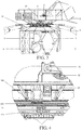
Figure 1 shows a side view of a preferred embodiment of a ground station of a tropospheric wind generator according to the present invention; -
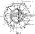
Figure 2 shows a plan view of the station ofFigure 1 ; -
Figure 3 shows an enlarged view of the contents of circle III ofFigure 1 ; -
Figure 4 shows an enlarged view of the contents of circle IV ofFigure 3 ; and -
Figure 5 shows an enlarged view of the contents of circle V ofFigure 2 . - With reference to the Figures it is possible to note that a
ground station 1 of a tropospheric wind generator is of the type adapted to deviate tethers connecting at least one kite through at least onelever 2 capable of being oriented. - The
ground station 1 comprises acarrier structure 3 surmounted by a firstmotored joint 4 and a secondmotored joint 5. - The first
motored joint 4 allows a free swinging rotation of thelever 2 capable of being oriented. - The second
motored joint 5 allows a free lifting rotation of thelever 2 capable of being oriented. - Preferably, the second
motored joint 5 is placed on board the firstmotored joint 4. - Moreover, the
ground station 1 comprises amachine room 6 occupied by at least one pair ofdrums 7, pulleys andalternators 8. - In particular, the
carrier structure 3 comprises a reticular shell composed of radialcurved rods 31 having the ends connected by one or morehorizontal rings - The
machine room 6 is integral with the firstmotored joint 4 to be able to rotate with respect to thecarrier structure 3. - The
machine room 6 comprises at least one pair ofdrums 7, pulleys andalternators 8, electric panels and actuators (not shown). - Preferably, the radial
curved rods 31 are angularly at the same distance and connected to at least one pair ofhorizontal rings motored joint 4. Still more preferably, at the height of anupper ring 33 belonging to such pair ofhorizontal rings motored joint 4. - Preferably, at least one motor-reducer (10) fastened to the
carrier structure 3 is connected to a gear composed of apinion 101 and atoothed wheel 102 integral with the first motoredjoint 4. - An external cover (not shown) fastened to the
carrier structure 3 allows creating a sheltered environment in the space surrounding themachine room 6. - The
carrier structure 3 behaves like a spring adapted to dampen force peaks created by the kite subjected to wind bursts. - The
carrier structure 3 subjected to the traction forces of the tethers is sized to support stresses of the order of 1,000 KN. - The electric panels placed in the
machine room 6 are equipped with servo-controls. - In the lower part of the
machine room 6 thedrums 7 are placed, adapted to allow winding the tethers connecting the kites. - The
drums 7 axially slide to avoid accumulations of tethers. The rotation and translation motions of the mutuallydependent drums 7 are actuated through thealternators 8. - Electric components are distributed in the whole structure of the
ground station 1. - Chains (not shown) are placed on the moving parts and are adapted to carry wirings and pipes of the cooling plant. Electric panels fastened to the
machine room 6 contain servo-controls to perform lifting and swinging of theinclined rod 2 and to actuate pulleys andalternators 8 associated with thedrums 7. - A battery of super-capacitors (not shown) are placed on the fixed parts and have the function of reducing the oscillation of the power delivered to the mains when producing and of accumulating the electric energy which is used during the recovery phase of the inflatable sail.
- An electric connection between the fixed and moving parts occurs by means of sliding
contacts upper ring 33 of thecarrier structure 3.
Claims (6)
- Ground station (1) of a tropospheric wind generator, of the type adapted to deviate tethers connecting at least one kite through at least one lever (2) capable of being oriented, comprising a carrier structure (3) surmounted by a first motored joint (4) adapted to allow a free swinging rotation of the lever (2) capable of being oriented and a second motored joint (5) adapted to allow a free lifting rotation of the lever (2) capable of being oriented and a machine room (6), characterized in that said carrier structure (3) comprises a reticular shell composed of radial curved rods (31) having the ends connected by two or more horizontal rings (32, 33) to allow deformations adapted to absorb and dampen force peaks transmitted by said at least one kite, said radial curved rods (31) being angularly at the same distance and connected to at least one pair of said horizontal rings (32, 33) respectively placed at the lower end at the level of the bearing ground and at the upper end at the level of said first motored joint (4).
- Ground station (1) of a tropospheric wind generator according to the previous claim, characterized in that said machine room (6) is integral with said first motored joint (4) to be able to rotate with respect to said carrier structure (3).
- Ground station (1) of a tropospheric wind generator according to claim 1, characterized in that said second motored joint (5) is placed on board of said first motored joint (4).
- Ground station (1) of a tropospheric wind generator according to the previous claim, characterized in that at the height of an upper ring (33) belonging to at least one pair of said horizontal rings (32, 33) at least one sliding bearing (9) is housed, to allow a rotation of said first motored joint (4).
- Ground station (1) of a tropospheric wind generator according to the previous claim, characterized in that at least one motor-reducer (10) fastened to said carrier structure (3) is connected to a gear composed of a pinion (101) and a toothed wheel (102) integral with said first motored joint (4).
- Ground station (1) of a tropospheric wind generator according to claim 1, characterized in that an electric connection between fixed and moving parts of said station (1) occurs by means of sliding contacts (111, 112) placed at the height of an upper ring (33) belonging to at least one of said pair of horizontal rings (32, 33).
Applications Claiming Priority (2)
| Application Number | Priority Date | Filing Date | Title |
|---|---|---|---|
| ITTO20150018 | 2015-01-12 | ||
| PCT/IT2016/000003 WO2016113765A1 (en) | 2015-01-12 | 2016-01-07 | Ground station of a tropospheric wind generator |
Publications (2)
| Publication Number | Publication Date |
|---|---|
| EP3245399A1 EP3245399A1 (en) | 2017-11-22 |
| EP3245399B1 true EP3245399B1 (en) | 2020-05-06 |
Family
ID=52577911
Family Applications (1)
| Application Number | Title | Priority Date | Filing Date |
|---|---|---|---|
| EP16714024.3A Active EP3245399B1 (en) | 2015-01-12 | 2016-01-07 | Ground station of a tropospheric wind generator |
Country Status (3)
| Country | Link |
|---|---|
| EP (1) | EP3245399B1 (en) |
| ES (1) | ES2809564T3 (en) |
| WO (1) | WO2016113765A1 (en) |
Family Cites Families (5)
| Publication number | Priority date | Publication date | Assignee | Title |
|---|---|---|---|---|
| WO2007133724A2 (en) * | 2006-05-12 | 2007-11-22 | Windlift, Llc | Tethered airfoil methods and systems |
| ITTO20080423A1 (en) | 2008-06-04 | 2008-09-03 | Massimo Ippolito | OPTIMIZED INFRASTRUCTURE OF MANEUVERING AND TAKEN ASSISTED TAKEOFF PROFILES FOR TROPOSFERIC WIND GENERATOR. |
| DE102008053818A1 (en) * | 2008-10-24 | 2010-04-29 | Nölting, Bengt, Dipl.-Phys. Dr. | Wind energy using method for electrical energy generation, involves stabilizing track of wagon using rail, and providing cluster of kites with lifting body that lifts-off kites during lull in wind |
| WO2013005182A2 (en) * | 2011-07-07 | 2013-01-10 | Hystad Jan | Wind power plant |
| ITTO20130752A1 (en) | 2013-09-13 | 2013-12-13 | Kite Gen Res Srl | PROCEDURE FOR THE MANAGEMENT, ADJUSTMENT AND CONTROL OF A WIND GENERATOR. |
-
2016
- 2016-01-07 WO PCT/IT2016/000003 patent/WO2016113765A1/en active Application Filing
- 2016-01-07 ES ES16714024T patent/ES2809564T3/en active Active
- 2016-01-07 EP EP16714024.3A patent/EP3245399B1/en active Active
Non-Patent Citations (1)
| Title |
|---|
| None * |
Also Published As
| Publication number | Publication date |
|---|---|
| ES2809564T3 (en) | 2021-03-04 |
| WO2016113765A1 (en) | 2016-07-21 |
| EP3245399A1 (en) | 2017-11-22 |
Similar Documents
| Publication | Publication Date | Title |
|---|---|---|
| KR101611779B1 (en) | Kite ground station and system using same | |
| ES2471116T3 (en) | Wind power converter using kites | |
| EP3224471B1 (en) | A winch | |
| WO2010122292A2 (en) | Improvements in or relating to the extraction of energy from the wind | |
| RU2615549C2 (en) | Wind energy conversion system by moving on rail modules towed by kites and electrical energy generation process by means of such system | |
| US20150008678A1 (en) | Airborne wind energy conversion system with endless belt and related systems and methods | |
| US7847426B1 (en) | Wind power generation | |
| MXPA06015165A (en) | Vertical-axis wind turbine. | |
| JP2015514893A (en) | System and method for producing wind energy in the air | |
| WO2016148870A1 (en) | Pivoting perch for flying wind turbine parking | |
| WO2011003009A2 (en) | Turbine wheel | |
| US20160002013A1 (en) | Tether Winding | |
| WO2018102124A1 (en) | A floating counter-balanced levelwind carrier system | |
| EP3218598B1 (en) | A kite | |
| EP3245399B1 (en) | Ground station of a tropospheric wind generator | |
| EP2672109A1 (en) | System and method for converting wind flow energy into mechanical, thermodynamic or electrical energy | |
| EP3120019B1 (en) | System and process for managing and controlling the flight of wing profiles, in particular for wind generator | |
| EP3256721B1 (en) | Improved infrastructure for driving kites of a tropospheric wind generator | |
| EP2791504B1 (en) | Kite ground station and system using same |
Legal Events
| Date | Code | Title | Description |
|---|---|---|---|
| STAA | Information on the status of an ep patent application or granted ep patent |
Free format text: STATUS: THE INTERNATIONAL PUBLICATION HAS BEEN MADE |
|
| PUAI | Public reference made under article 153(3) epc to a published international application that has entered the european phase |
Free format text: ORIGINAL CODE: 0009012 |
|
| STAA | Information on the status of an ep patent application or granted ep patent |
Free format text: STATUS: REQUEST FOR EXAMINATION WAS MADE |
|
| 17P | Request for examination filed |
Effective date: 20170804 |
|
| AK | Designated contracting states |
Kind code of ref document: A1 Designated state(s): AL AT BE BG CH CY CZ DE DK EE ES FI FR GB GR HR HU IE IS IT LI LT LU LV MC MK MT NL NO PL PT RO RS SE SI SK SM TR |
|
| AX | Request for extension of the european patent |
Extension state: BA ME |
|
| RIN1 | Information on inventor provided before grant (corrected) |
Inventor name: IPPOLITO, MASSIMO |
|
| DAV | Request for validation of the european patent (deleted) | ||
| DAX | Request for extension of the european patent (deleted) | ||
| GRAP | Despatch of communication of intention to grant a patent |
Free format text: ORIGINAL CODE: EPIDOSNIGR1 |
|
| STAA | Information on the status of an ep patent application or granted ep patent |
Free format text: STATUS: GRANT OF PATENT IS INTENDED |
|
| INTG | Intention to grant announced |
Effective date: 20191218 |
|
| GRAS | Grant fee paid |
Free format text: ORIGINAL CODE: EPIDOSNIGR3 |
|
| GRAA | (expected) grant |
Free format text: ORIGINAL CODE: 0009210 |
|
| STAA | Information on the status of an ep patent application or granted ep patent |
Free format text: STATUS: THE PATENT HAS BEEN GRANTED |
|
| AK | Designated contracting states |
Kind code of ref document: B1 Designated state(s): AL AT BE BG CH CY CZ DE DK EE ES FI FR GB GR HR HU IE IS IT LI LT LU LV MC MK MT NL NO PL PT RO RS SE SI SK SM TR |
|
| REG | Reference to a national code |
Ref country code: GB Ref legal event code: FG4D |
|
| REG | Reference to a national code |
Ref country code: AT Ref legal event code: REF Ref document number: 1267153 Country of ref document: AT Kind code of ref document: T Effective date: 20200515 Ref country code: CH Ref legal event code: EP |
|
| REG | Reference to a national code |
Ref country code: IE Ref legal event code: FG4D |
|
| REG | Reference to a national code |
Ref country code: DE Ref legal event code: R096 Ref document number: 602016035712 Country of ref document: DE |
|
| REG | Reference to a national code |
Ref country code: LT Ref legal event code: MG4D |
|
| REG | Reference to a national code |
Ref country code: NL Ref legal event code: MP Effective date: 20200506 |
|
| PG25 | Lapsed in a contracting state [announced via postgrant information from national office to epo] |
Ref country code: LT Free format text: LAPSE BECAUSE OF FAILURE TO SUBMIT A TRANSLATION OF THE DESCRIPTION OR TO PAY THE FEE WITHIN THE PRESCRIBED TIME-LIMIT Effective date: 20200506 Ref country code: IS Free format text: LAPSE BECAUSE OF FAILURE TO SUBMIT A TRANSLATION OF THE DESCRIPTION OR TO PAY THE FEE WITHIN THE PRESCRIBED TIME-LIMIT Effective date: 20200906 Ref country code: PT Free format text: LAPSE BECAUSE OF FAILURE TO SUBMIT A TRANSLATION OF THE DESCRIPTION OR TO PAY THE FEE WITHIN THE PRESCRIBED TIME-LIMIT Effective date: 20200907 Ref country code: FI Free format text: LAPSE BECAUSE OF FAILURE TO SUBMIT A TRANSLATION OF THE DESCRIPTION OR TO PAY THE FEE WITHIN THE PRESCRIBED TIME-LIMIT Effective date: 20200506 Ref country code: GR Free format text: LAPSE BECAUSE OF FAILURE TO SUBMIT A TRANSLATION OF THE DESCRIPTION OR TO PAY THE FEE WITHIN THE PRESCRIBED TIME-LIMIT Effective date: 20200807 Ref country code: NO Free format text: LAPSE BECAUSE OF FAILURE TO SUBMIT A TRANSLATION OF THE DESCRIPTION OR TO PAY THE FEE WITHIN THE PRESCRIBED TIME-LIMIT Effective date: 20200806 Ref country code: SE Free format text: LAPSE BECAUSE OF FAILURE TO SUBMIT A TRANSLATION OF THE DESCRIPTION OR TO PAY THE FEE WITHIN THE PRESCRIBED TIME-LIMIT Effective date: 20200506 |
|
| PG25 | Lapsed in a contracting state [announced via postgrant information from national office to epo] |
Ref country code: BG Free format text: LAPSE BECAUSE OF FAILURE TO SUBMIT A TRANSLATION OF THE DESCRIPTION OR TO PAY THE FEE WITHIN THE PRESCRIBED TIME-LIMIT Effective date: 20200806 Ref country code: RS Free format text: LAPSE BECAUSE OF FAILURE TO SUBMIT A TRANSLATION OF THE DESCRIPTION OR TO PAY THE FEE WITHIN THE PRESCRIBED TIME-LIMIT Effective date: 20200506 Ref country code: HR Free format text: LAPSE BECAUSE OF FAILURE TO SUBMIT A TRANSLATION OF THE DESCRIPTION OR TO PAY THE FEE WITHIN THE PRESCRIBED TIME-LIMIT Effective date: 20200506 Ref country code: LV Free format text: LAPSE BECAUSE OF FAILURE TO SUBMIT A TRANSLATION OF THE DESCRIPTION OR TO PAY THE FEE WITHIN THE PRESCRIBED TIME-LIMIT Effective date: 20200506 |
|
| REG | Reference to a national code |
Ref country code: AT Ref legal event code: MK05 Ref document number: 1267153 Country of ref document: AT Kind code of ref document: T Effective date: 20200506 |
|
| PG25 | Lapsed in a contracting state [announced via postgrant information from national office to epo] |
Ref country code: AL Free format text: LAPSE BECAUSE OF FAILURE TO SUBMIT A TRANSLATION OF THE DESCRIPTION OR TO PAY THE FEE WITHIN THE PRESCRIBED TIME-LIMIT Effective date: 20200506 Ref country code: NL Free format text: LAPSE BECAUSE OF FAILURE TO SUBMIT A TRANSLATION OF THE DESCRIPTION OR TO PAY THE FEE WITHIN THE PRESCRIBED TIME-LIMIT Effective date: 20200506 |
|
| PG25 | Lapsed in a contracting state [announced via postgrant information from national office to epo] |
Ref country code: CZ Free format text: LAPSE BECAUSE OF FAILURE TO SUBMIT A TRANSLATION OF THE DESCRIPTION OR TO PAY THE FEE WITHIN THE PRESCRIBED TIME-LIMIT Effective date: 20200506 Ref country code: EE Free format text: LAPSE BECAUSE OF FAILURE TO SUBMIT A TRANSLATION OF THE DESCRIPTION OR TO PAY THE FEE WITHIN THE PRESCRIBED TIME-LIMIT Effective date: 20200506 Ref country code: SM Free format text: LAPSE BECAUSE OF FAILURE TO SUBMIT A TRANSLATION OF THE DESCRIPTION OR TO PAY THE FEE WITHIN THE PRESCRIBED TIME-LIMIT Effective date: 20200506 Ref country code: DK Free format text: LAPSE BECAUSE OF FAILURE TO SUBMIT A TRANSLATION OF THE DESCRIPTION OR TO PAY THE FEE WITHIN THE PRESCRIBED TIME-LIMIT Effective date: 20200506 Ref country code: AT Free format text: LAPSE BECAUSE OF FAILURE TO SUBMIT A TRANSLATION OF THE DESCRIPTION OR TO PAY THE FEE WITHIN THE PRESCRIBED TIME-LIMIT Effective date: 20200506 Ref country code: RO Free format text: LAPSE BECAUSE OF FAILURE TO SUBMIT A TRANSLATION OF THE DESCRIPTION OR TO PAY THE FEE WITHIN THE PRESCRIBED TIME-LIMIT Effective date: 20200506 |
|
| REG | Reference to a national code |
Ref country code: DE Ref legal event code: R097 Ref document number: 602016035712 Country of ref document: DE |
|
| PG25 | Lapsed in a contracting state [announced via postgrant information from national office to epo] |
Ref country code: PL Free format text: LAPSE BECAUSE OF FAILURE TO SUBMIT A TRANSLATION OF THE DESCRIPTION OR TO PAY THE FEE WITHIN THE PRESCRIBED TIME-LIMIT Effective date: 20200506 Ref country code: SK Free format text: LAPSE BECAUSE OF FAILURE TO SUBMIT A TRANSLATION OF THE DESCRIPTION OR TO PAY THE FEE WITHIN THE PRESCRIBED TIME-LIMIT Effective date: 20200506 |
|
| REG | Reference to a national code |
Ref country code: ES Ref legal event code: FG2A Ref document number: 2809564 Country of ref document: ES Kind code of ref document: T3 Effective date: 20210304 |
|
| PLBE | No opposition filed within time limit |
Free format text: ORIGINAL CODE: 0009261 |
|
| STAA | Information on the status of an ep patent application or granted ep patent |
Free format text: STATUS: NO OPPOSITION FILED WITHIN TIME LIMIT |
|
| 26N | No opposition filed |
Effective date: 20210209 |
|
| PG25 | Lapsed in a contracting state [announced via postgrant information from national office to epo] |
Ref country code: SI Free format text: LAPSE BECAUSE OF FAILURE TO SUBMIT A TRANSLATION OF THE DESCRIPTION OR TO PAY THE FEE WITHIN THE PRESCRIBED TIME-LIMIT Effective date: 20200506 |
|
| PG25 | Lapsed in a contracting state [announced via postgrant information from national office to epo] |
Ref country code: MC Free format text: LAPSE BECAUSE OF FAILURE TO SUBMIT A TRANSLATION OF THE DESCRIPTION OR TO PAY THE FEE WITHIN THE PRESCRIBED TIME-LIMIT Effective date: 20200506 |
|
| REG | Reference to a national code |
Ref country code: CH Ref legal event code: PL |
|
| PG25 | Lapsed in a contracting state [announced via postgrant information from national office to epo] |
Ref country code: LU Free format text: LAPSE BECAUSE OF NON-PAYMENT OF DUE FEES Effective date: 20210107 |
|
| REG | Reference to a national code |
Ref country code: BE Ref legal event code: MM Effective date: 20210131 |
|
| PG25 | Lapsed in a contracting state [announced via postgrant information from national office to epo] |
Ref country code: CH Free format text: LAPSE BECAUSE OF NON-PAYMENT OF DUE FEES Effective date: 20210131 Ref country code: LI Free format text: LAPSE BECAUSE OF NON-PAYMENT OF DUE FEES Effective date: 20210131 |
|
| PG25 | Lapsed in a contracting state [announced via postgrant information from national office to epo] |
Ref country code: IE Free format text: LAPSE BECAUSE OF NON-PAYMENT OF DUE FEES Effective date: 20210107 |
|
| PG25 | Lapsed in a contracting state [announced via postgrant information from national office to epo] |
Ref country code: BE Free format text: LAPSE BECAUSE OF NON-PAYMENT OF DUE FEES Effective date: 20210131 |
|
| PGFP | Annual fee paid to national office [announced via postgrant information from national office to epo] |
Ref country code: FR Payment date: 20230125 Year of fee payment: 8 Ref country code: ES Payment date: 20230201 Year of fee payment: 8 |
|
| PG25 | Lapsed in a contracting state [announced via postgrant information from national office to epo] |
Ref country code: HU Free format text: LAPSE BECAUSE OF FAILURE TO SUBMIT A TRANSLATION OF THE DESCRIPTION OR TO PAY THE FEE WITHIN THE PRESCRIBED TIME-LIMIT; INVALID AB INITIO Effective date: 20160107 |
|
| PGFP | Annual fee paid to national office [announced via postgrant information from national office to epo] |
Ref country code: IT Payment date: 20230103 Year of fee payment: 8 Ref country code: GB Payment date: 20230127 Year of fee payment: 8 Ref country code: DE Payment date: 20230127 Year of fee payment: 8 |
|
| PG25 | Lapsed in a contracting state [announced via postgrant information from national office to epo] |
Ref country code: CY Free format text: LAPSE BECAUSE OF FAILURE TO SUBMIT A TRANSLATION OF THE DESCRIPTION OR TO PAY THE FEE WITHIN THE PRESCRIBED TIME-LIMIT Effective date: 20200506 |