EP3244991B1 - Container with a stirrer device for fluid products - Google Patents
Container with a stirrer device for fluid products Download PDFInfo
- Publication number
- EP3244991B1 EP3244991B1 EP16709118.0A EP16709118A EP3244991B1 EP 3244991 B1 EP3244991 B1 EP 3244991B1 EP 16709118 A EP16709118 A EP 16709118A EP 3244991 B1 EP3244991 B1 EP 3244991B1
- Authority
- EP
- European Patent Office
- Prior art keywords
- stirrer
- container
- elements
- hereinbefore
- units
- Prior art date
- Legal status (The legal status is an assumption and is not a legal conclusion. Google has not performed a legal analysis and makes no representation as to the accuracy of the status listed.)
- Active
Links
Images

Classifications
-
- B—PERFORMING OPERATIONS; TRANSPORTING
- B01—PHYSICAL OR CHEMICAL PROCESSES OR APPARATUS IN GENERAL
- B01F—MIXING, e.g. DISSOLVING, EMULSIFYING OR DISPERSING
- B01F33/00—Other mixers; Mixing plants; Combinations of mixers
- B01F33/80—Mixing plants; Combinations of mixers
- B01F33/84—Mixing plants with mixing receptacles receiving material dispensed from several component receptacles, e.g. paint tins
-
- B—PERFORMING OPERATIONS; TRANSPORTING
- B01—PHYSICAL OR CHEMICAL PROCESSES OR APPARATUS IN GENERAL
- B01F—MIXING, e.g. DISSOLVING, EMULSIFYING OR DISPERSING
- B01F27/00—Mixers with rotary stirring devices in fixed receptacles; Kneaders
- B01F27/05—Stirrers
- B01F27/11—Stirrers characterised by the configuration of the stirrers
- B01F27/112—Stirrers characterised by the configuration of the stirrers with arms, paddles, vanes or blades
- B01F27/1125—Stirrers characterised by the configuration of the stirrers with arms, paddles, vanes or blades with vanes or blades extending parallel or oblique to the stirrer axis
- B01F27/11251—Stirrers characterised by the configuration of the stirrers with arms, paddles, vanes or blades with vanes or blades extending parallel or oblique to the stirrer axis having holes in the surface
-
- B—PERFORMING OPERATIONS; TRANSPORTING
- B01—PHYSICAL OR CHEMICAL PROCESSES OR APPARATUS IN GENERAL
- B01F—MIXING, e.g. DISSOLVING, EMULSIFYING OR DISPERSING
- B01F27/00—Mixers with rotary stirring devices in fixed receptacles; Kneaders
- B01F27/80—Mixers with rotary stirring devices in fixed receptacles; Kneaders with stirrers rotating about a substantially vertical axis
- B01F27/85—Mixers with rotary stirring devices in fixed receptacles; Kneaders with stirrers rotating about a substantially vertical axis with two or more stirrers on separate shafts
- B01F27/851—Mixers with rotary stirring devices in fixed receptacles; Kneaders with stirrers rotating about a substantially vertical axis with two or more stirrers on separate shafts the receptacle being subdivided in adjacent compartments
-
- B—PERFORMING OPERATIONS; TRANSPORTING
- B01—PHYSICAL OR CHEMICAL PROCESSES OR APPARATUS IN GENERAL
- B01F—MIXING, e.g. DISSOLVING, EMULSIFYING OR DISPERSING
- B01F27/00—Mixers with rotary stirring devices in fixed receptacles; Kneaders
- B01F27/80—Mixers with rotary stirring devices in fixed receptacles; Kneaders with stirrers rotating about a substantially vertical axis
- B01F27/90—Mixers with rotary stirring devices in fixed receptacles; Kneaders with stirrers rotating about a substantially vertical axis with paddles or arms
- B01F27/906—Mixers with rotary stirring devices in fixed receptacles; Kneaders with stirrers rotating about a substantially vertical axis with paddles or arms with fixed axis
-
- B—PERFORMING OPERATIONS; TRANSPORTING
- B01—PHYSICAL OR CHEMICAL PROCESSES OR APPARATUS IN GENERAL
- B01F—MIXING, e.g. DISSOLVING, EMULSIFYING OR DISPERSING
- B01F35/00—Accessories for mixers; Auxiliary operations or auxiliary devices; Parts or details of general application
- B01F35/50—Mixing receptacles
- B01F35/54—Closely surrounding the rotating element
-
- B—PERFORMING OPERATIONS; TRANSPORTING
- B01—PHYSICAL OR CHEMICAL PROCESSES OR APPARATUS IN GENERAL
- B01F—MIXING, e.g. DISSOLVING, EMULSIFYING OR DISPERSING
- B01F2101/00—Mixing characterised by the nature of the mixed materials or by the application field
- B01F2101/30—Mixing paints or paint ingredients, e.g. pigments, dyes, colours, lacquers or enamel
Definitions
- the present invention concerns a container comprising a stirrer device for fluid products, such as for example colorant liquids, bases for paints, varnishes, enamels, inks and suchlike, suitable to be installed on machines for dispensing or distributing said fluid products.
- fluid products such as for example colorant liquids, bases for paints, varnishes, enamels, inks and suchlike, suitable to be installed on machines for dispensing or distributing said fluid products.
- One purpose of the present invention is instead to provide a container for fluid products such as colorants or suchlike, small to medium in size and therefore suitable to be inserted, together with a plurality of other containers of the same type, into a dispensing machine for said fluid products, and having a stirrer device configured so as to allow a complete homogenization and mixing of the fluid product contained inside it, until it is selectively delivered for the preparation of the colorant determined by the desired mixture.
- each of the stirrer units comprises at least two stirrer elements, for example blades, attached on rotating shafts and axially disposed at respective different angles so as not to have a zone around each rotating shaft that is not spatially affected by a stirrer element.
- this conformation of the container with co-penetrating cylindrical zones allows to further increase the compacting of the containers, compared with the solution of EP'11744826 which is already an improvement, thus allowing to obtain, given the same overall bulk of the machine for dispensing colorants, a greater number of containers, i.e. with the same number of containers a smaller overall bulk of the dispensing machine.
- the stirrer elements have one or more through holes disposed along a vertical axis of the stirrer element translated toward the outside with respect to the central vertical axis of the stirrer element.
- the stirrer elements can have different configurations, for example rectangular or any other quadrangular shape, possibly rounded.
- the stirrer elements located more adjacent to the bottom of the container, and comprised in each of the two stirrer units can have an inclined and pointed shape so as to scrape the bottom of the container in order to remove possible sedimentations of paint.
- the stirrer units are installed so as to have between them a radial stagger that can be 90°, or 45° or 30°, or other angles suitable for the number of stirrer elements comprised in each stirrer unit.
- each of the stirrer units is connected to a corresponding idle toothed wheel, and both the idle toothed wheels are coupled with a third toothed wheel that imparts rotation motion to the stirrer units by means of a motor, keeping the angle of stagger constant between the stirrer units.
- each stirrer unit is associated with its own independent motor; the two motors are synchronized, for example electronically, in order to maintain the initial stagger and to prevent impacts or interference between the stirrer elements of the stirrer units.
- the invention concerns a container with a stirrer device for fluid products 10, hereafter referred to simply as container, which comprises a tank 11.
- the fluid product is indicated as a paint, but it can be any other colorant liquid, such as for example a base for paints, an enamel, an ink or suchlike.
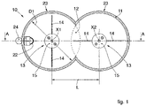
- the tank 11 can be configured by joining together two cylinders 23, in this case having the same diameter D 1 and the same height and which share a zone, called overlapping zone 12 (see figs. 1 and 2 ).
- the overlapping zone 12 is caused by the co-penetration of the two cylinders 23.
- This configuration of the tank 11 will be defined hereafter as an "8"-shaped configuration.
- a multitude of tanks 11 of the same type can be installed inside an internal compartment that defines an available surface 25 of a machine for dispensing fluid products, such as for example colorants or suchlike.
- the tanks 11 according to the present invention can be installed, given the same available surface 25 in a dispensing machine for fluid products, in a greater number than known containers 110 (see the comparison between fig. 4 , which shows the solution of EP'1744826 and fig. 5 which shows the solution according to the present invention).
- the tank 11, in this particular embodiment, comprises two longitudinal axes X 1 and X 2 , each defining the axis of the corresponding cylinder 23, having a distance L between them, less than D 1 .
- respective stirrer units 13 can be installed, each provided with an axially rotating shaft 15 coaxial with the respective cylinder 23.
- stirrer element 14 stirring each of the spatial portions that make up the volume occupied by the fluid in the container 11, including the area near the bottom of the tank 11.
- the through holes 16 are disposed along an imaginary vertical axis of the stirrer elements 14, translated with respect to the central vertical axis (Y1) of the stirrer element 14 toward the outside.
- One or more suction elements 22 are comprised on the lower part of the tank 11, and can be connected by suitable pipes to pumping delivery means (not shown in the drawings).
- connection elements 24 are comprised on the upper part of the tank 11, to recirculate the fluid, and are connected by suitable pipes to metering elements (not shown in the drawings).
Landscapes
- Chemical & Material Sciences (AREA)
- Chemical Kinetics & Catalysis (AREA)
- Mixers Of The Rotary Stirring Type (AREA)
- Coating Apparatus (AREA)
- Filling Or Emptying Of Bunkers, Hoppers, And Tanks (AREA)
Description
- The present invention concerns a container comprising a stirrer device for fluid products, such as for example colorant liquids, bases for paints, varnishes, enamels, inks and suchlike, suitable to be installed on machines for dispensing or distributing said fluid products.
- In particular, the container with the stirrer device for fluid products according to the present invention allows a complete and uniform homogenization of the fluid product contained inside it, facilitated by the particular configuration of the container, increasing the available capacity but at the same time leaving the overall bulk of the dispensing machine substantially unchanged.
- Machines are known for dispensing or distributing fluid products, such as for example colorants of different shade or color, able to be mixed with each other and/or added to a base substance to make up a varnish or paint of a determinate color.
- Known machines normally comprise a plurality of containers containing a determinate colorant, selectively connectable to one or more delivery nozzles and associated with respective pump means that cause the selective delivery of the fluid product contained in them in a suitably chosen quantity, for example using an electronic processor.
- Each container comprises inside it a stirrer device, selectively activated, able to prevent the heaviest components present in the fluid from depositing on the bottom of the container, with consequent drying out of the fluid.
- In order to prepare the most requested colored varnishes or paints, it is provided to use some colorants more frequently than others, and therefore some containers are finished more quickly than others: this obviously entails more frequent filling or topping up operations which, in some cases, require no less than the stoppage of the dispensing machine.
- One known solution to this disadvantage, according to
EP 1744826 B1 , is to provide containers for fluid products with a greater capacity, having a conformation shaped to define an internal compartment substantially consisting of two cylindrical zones, reciprocally not co-penetrating and connected by an intermediate zone also defining a containing volume of the fluid product. This known technique allows to increase the overall volume for containing the fluid product, obtaining a single container by joining together two cylinders and an additional volume given by the intermediate zone. - It is also known that any container for fluid products needs a stirrer device to prevent the obsolescence of the fluid substance contained in the container. Indeed, if there is no stirring, the fluid product tends to dry out and to deposit its heaviest components on the bottom of the container.
- It has been found that, in a container for fluid products configured according to
EP 1744826 B1 , there are difficulties in stirring all the fluid product contained inside because the stirrer elements provided in correspondence with the cylindrical zones have difficulty in affecting the accumulation zone corresponding to the intermediate zone. - This causes the fluid in the intermediate zone to dry out, and therefore it is not possible to have a homogenous mixing of the fluid inside the whole volume of the internal compartment of the container.
- Document
DE 417549C (DE'549) describes a machine for refining chocolate that has a tower with a section shape defined by two co-penetrating cylindrical zones in which there are respective mixing elements of the type with a shaft and blades. - This document does not concern a container for fluid products such as colorants or suchlike, suitable to be associated with other analogous containers to a dispensing machine and able to be associated with selective delivery means, but a stable container, large-sized, normally resting on the ground, and intended for long-duration treatments for food products.
- Document
DE 1815582 A1 describes a machine for mixing solid substances in powder, aggregate or liquid form, inside a receptacle that is also conformed with a section shape defined by two partly co-penetrating cylindrical zones, each associated with a blade-type stirrer element. - This document also shows a machine for stirring and treating substances, but not a container for colorant products or suchlike suitable to be inserted together with other containers in a machine for selectively dispensing colorants.
- The same or similar considerations also apply for
FR 319290 A WO 92/00665 A1 - All these prior art documents concern big tanks or towers, suitable for autonomous use, for treating and/or preserving substances, normally food or pharmaceutical products.
- One purpose of the present invention is instead to provide a container for fluid products such as colorants or suchlike, small to medium in size and therefore suitable to be inserted, together with a plurality of other containers of the same type, into a dispensing machine for said fluid products, and having a stirrer device configured so as to allow a complete homogenization and mixing of the fluid product contained inside it, until it is selectively delivered for the preparation of the colorant determined by the desired mixture.
- Another purpose of the present invention is to improve the configuration of the container for fluid products so as to maintain the advantages given by the greater volume of the internal compartment of the dispensing machine, keeping the bulk of the container unchanged with respect to the dispensing machine on which it is installed, and at the same time eliminating the intermediate zone where stirring is reduced.
- Another purpose of the present invention is to improve the disposition and geometry of the stirrer elements inside the container so that there are no zones where the fluid contained inside the container has a substantially zero speed, and at the same time obtains a reduction in the energy needed to move the stirrer elements compared with the state of the art.
- The Applicant has devised, tested and embodied the present invention to overcome the shortcomings of the state of the art and to obtain these and other purposes and advantages.
- The present invention is set forth and characterized in the independent claims, while the dependent claims describe other characteristics of the invention or variants to the main inventive idea.
- In accordance with the above purposes, a container with a stirrer device according to the present invention is a container according to claim 1.
- According to one formulation of the present invention, each of the stirrer units comprises at least two stirrer elements, for example blades, attached on rotating shafts and axially disposed at respective different angles so as not to have a zone around each rotating shaft that is not spatially affected by a stirrer element.
- According to another characteristic of the present invention, thanks to this conformation of the tank and stirrer elements, the overlapping area is also affected cyclically, reducing to a minimum the intermediate zone, not mixed, and even cancelling it.
- Furthermore, this conformation of the container with co-penetrating cylindrical zones allows to further increase the compacting of the containers, compared with the solution of EP'11744826 which is already an improvement, thus allowing to obtain, given the same overall bulk of the machine for dispensing colorants, a greater number of containers, i.e. with the same number of containers a smaller overall bulk of the dispensing machine.
- According to another characteristic of the present invention, the stirrer elements have one or more through holes disposed along a vertical axis of the stirrer element translated toward the outside with respect to the central vertical axis of the stirrer element.
- Furthermore, the stirrer elements can be made of any suitable material, for example resistant plastic material or steel, or stainless steel or aluminum alloy.
- The stirrer elements can have different configurations, for example rectangular or any other quadrangular shape, possibly rounded.
- Furthermore, the surface of the stirrer elements can be continuous, or can have through holes disposed on the surface in different ways, or they can be flat or inclined with respect to the axis of rotation.
- According to another characteristic of the present invention, the stirrer elements located more adjacent to the bottom of the container, and comprised in each of the two stirrer units, can have an inclined and pointed shape so as to scrape the bottom of the container in order to remove possible sedimentations of paint.
- According to another characteristic of the present invention, the stirrer units are installed so as to have between them a radial stagger that can be 90°, or 45° or 30°, or other angles suitable for the number of stirrer elements comprised in each stirrer unit.
- According to another formulation of the present invention, each of the stirrer units is connected to a corresponding idle toothed wheel, and both the idle toothed wheels are coupled with a third toothed wheel that imparts rotation motion to the stirrer units by means of a motor, keeping the angle of stagger constant between the stirrer units.
- According to another formulation, each stirrer unit is associated with its own independent motor; the two motors are synchronized, for example electronically, in order to maintain the initial stagger and to prevent impacts or interference between the stirrer elements of the stirrer units.
- These and other characteristics of the present invention will become apparent from the following description of some forms of embodiment, given as a non-restrictive example with reference to the attached drawings wherein:
-
fig. 1 is a plan view of the container with stirrer device in a particular embodiment; -
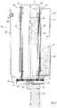
fig. 2 is a section view of the container with stirrer device in a particular embodiment; -
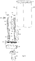
fig. 3 is a perspective view of the container with stirrer device; -
fig. 4 shows a possible lay-out of a dispensing machine for colorants with a plurality of state-of-the-art containers; -
fig. 5 shows a possible lay-out of a dispensing machine for colorants with a plurality of containers according to the present invention. - To facilitate comprehension, the same reference numbers have been used, where possible, to identify identical common elements in the drawings. It is understood that elements and characteristics of one form of embodiment can conveniently be incorporated into other forms of embodiment without further clarifications.
- We shall now refer in detail to the various forms of embodiment of the present invention, of which one or more examples are shown in the attached drawings. Each example is supplied by way of illustration of the invention and shall not be understood as a limitation thereof. For example, the characteristics shown or described insomuch as they are part of one form of embodiment can be adopted on, or in association with, other forms of embodiment to produce another form of embodiment.
- According to the embodiments in
figs. 1 ,2 and3 , the invention concerns a container with a stirrer device forfluid products 10, hereafter referred to simply as container, which comprises atank 11. - Hereafter in the description, merely by way of non-restrictive example, the fluid product is indicated as a paint, but it can be any other colorant liquid, such as for example a base for paints, an enamel, an ink or suchlike.
- In a particular embodiment, the
tank 11 can be configured by joining together twocylinders 23, in this case having the same diameter D1 and the same height and which share a zone, called overlapping zone 12 (seefigs. 1 and2 ). Theoverlapping zone 12 is caused by the co-penetration of the twocylinders 23. This configuration of thetank 11 will be defined hereafter as an "8"-shaped configuration. - According to one embodiment of the present invention, a multitude of
tanks 11 of the same type can be installed inside an internal compartment that defines anavailable surface 25 of a machine for dispensing fluid products, such as for example colorants or suchlike. - Since they have an
overlapping zone 12 and do not have anyintermediate segment 112, likecontainers 110 in the state of the art, thetanks 11 according to the present invention can be installed, given the sameavailable surface 25 in a dispensing machine for fluid products, in a greater number than known containers 110 (see the comparison betweenfig. 4 , which shows the solution of EP'1744826 andfig. 5 which shows the solution according to the present invention). - This allows to further increase, compared with the solution of EP'1744826 (which is already an improvement), the compacting of the containers, thus allowing to obtain, given the same overall bulk of the dispensing machine, a greater number of fluid product containers, that is, with the same number of containers, a lower overall bulk of the dispensing machine.
- The
tank 11, in this particular embodiment, comprises two longitudinal axes X1 and X2, each defining the axis of thecorresponding cylinder 23, having a distance L between them, less than D1. In substantial correspondence with the longitudinal axes X1 and X2,respective stirrer units 13 can be installed, each provided with an axially rotatingshaft 15 coaxial with therespective cylinder 23. - The
container 10 therefore comprises twostirrer units 13, one for eachcylinder 23, able to carry out the mechanical action of homogenizing and mixing the paint, to prevent it from hardening and drying. - In the solution shown here, each
stirrer unit 13 comprises twostirrer elements 14 attached radially on eachshaft 15. - The
stirrer elements 14, which can also have a different number and disposition than that shown here, can be made of resistant plastic material, or steel, or stainless steel or aluminum alloy. - Furthermore, the
stirrer elements 14 can be made in a plurality of forms, such as rectangular blades or any other quadrangular shape. They can be flat or inclined, their surface can be continuous or holed, or have surface ridges or incisions to facilitate the homogenization of the paint. - In one embodiment, during the rotation of the
shafts 15, thestirrer elements 14 are configured so that their contact surface with the fluid contained in thetank 11 is substantially perpendicular to the direction of rotation. - Moreover, according to this embodiment, the
stirrer elements 14 are conformed so that the fluid is moved substantially along at least the level reached by the fluid in thetank 11. - The
stirrer elements 14 are disposed substantially over the whole longitudinal extension of theshafts 15, so that eachshaft 15 does not have, along the longitudinal direction, one or more surface portions that are not affected spatially by astirrer element 14 attached to the correspondingshaft 15. - In other words, there is no zone around each
shaft 15 that is not spatially affected by acorresponding stirrer element 14 attached to theshaft 15, and that therefore is not stirred. - In this way, there is at least one
stirrer element 14 stirring each of the spatial portions that make up the volume occupied by the fluid in thecontainer 11, including the area near the bottom of thetank 11. - In a particular embodiment shown in
fig. 2 , thestirrer elements 14 can have one or more throughholes 16 to make them lighter, with a different diameter, bigger or smaller than each other. - The through holes 16 are disposed along an imaginary vertical axis of the
stirrer elements 14, translated with respect to the central vertical axis (Y1) of thestirrer element 14 toward the outside. - This strategy not only makes the
stirrer element 14 lighter, but also reduces its inertia moment, because portions farthest from the axis of rotation of theshaft 15 are removed and these, as is known, contribute most to the inertia moment associated with a rotating body. - This causes a reduction in the mechanical resistance and therefore there is a reduction in the mechanical energy needed to make the
shafts 15 with which thestirrer elements 14 are associated rotate. - Furthermore, the presence of the holes on the surface of the
stirrer elements 14 increases the circulation of the fluid in thetank 11 and hence the mixing of the fluid. In fact, during the rotation of thestirrer elements 14, if they are solid and perpendicular to the direction of rotation, the fluid near the surface of thestirrer element 14 comes to have a speed substantially the same as thestirrer element 14 itself. - Consequently, the fluid near the surface of the
stirrer element 14 does not mix with the remaining fluid, until a solid layer is created on the surface of thestirrer element 14. - In a particular embodiment, the
stirrer elements 14 can be attached on the axis of rotation of theshaft 15 in correspondence with their long side, or their short side, and the free side can be either perpendicular or inclined (for example inclination of 30°) with respect to the axis of theshaft 15. - In another embodiment, the
stirrer elements 14 adjacent to the bottom of thetank 11 can have an inclined and pointed shape so as to scrape the bottom of thetank 11 in order to remove possible sedimentations of paint. - In another embodiment, at least two
stirrer elements 14 can be attached on theshaft 15 in a position staggered with respect to each other by 180°, or more than twostirrer elements 14 can be attached, staggered with respect to each other by 90°, or with other possible angles. - The radial dimension of the
stirrer elements 14 with respect to the respective longitudinal axis X1 or X2 is such as to be slightly less than the radius of the cylinders 23 (D1/2), taking into consideration the bulk given by theshaft 15 and finding the correct compromise to prevent friction with the internal wall of thetank 11 and at the same time to maximize the cover of the overlappingzone 12 during the rotation of thestirrer elements 14. - One configuration of the
stirrer elements 14 obtained according to the above embodiment requires an accurate stagger of thestirrer elements 14 comprised in the twodifferent stirrer units 13, so as to allow an adequate homogenization of the whole internal volume of thetank 11, and to prevent thestirrer elements 14 from knocking against and interfering with each other. Therefore, between the twodifferent stirrer units 13 there must be a stagger sufficient to prevent interference of thestirrer elements 14, for example the stagger can be 90°, or 45° or 30° or any other stagger. The stagger must be adequate for the number ofstirrer elements 14 installed in eachstirrer unit 13, sufficient to prevent this disadvantage and to guarantee an adequate homogenization of the paint. - Each
stirrer unit 13, in the non-restrictive embodiment shown here, is connected to an idletoothed wheel 17 by coupling the lower end of theshaft 15. - A third
toothed wheel 18 is provided, able to impart motion to thestirrer units 13 by coupling with the two idletoothed wheels 17. - The third
toothed wheel 18 is connected by means of arotation shaft 20 to atimed motor 19. - The
motor 19 is located on aspecific support 21, positioned in the lower part of thetank 11 together with the idletoothed wheels 17 and the thirdtoothed wheel 18. - The
motor 19 imparts motion to the thirdtoothed wheel 18 which in turn transmits the motion to the two idletoothed wheels 17 and hence to thecorresponding stirrer units 13 to homogenize the paint inside thetank 11. - A movement system made in this way allows to be certain that the idle
toothed wheels 17, suitably engaged, ensure that the angle of stagger between the twostirrer units 13 remains constant, preventing any interference between thestirrer elements 14. - A movement system conceived differently, and not providing an independent, non-synchronized movement of the
stirrer units 13, would not guarantee a constant stagger due to the different densities of the paint, or other friction forces exerted on thestirrer unit 13. - One or
more suction elements 22 are comprised on the lower part of thetank 11, and can be connected by suitable pipes to pumping delivery means (not shown in the drawings). - One or
more connection elements 24 are comprised on the upper part of thetank 11, to recirculate the fluid, and are connected by suitable pipes to metering elements (not shown in the drawings). - The embodiments described above allow to optimize the homogenization of the paint, allowing to prevent dead zones, i.e. zones not affected by the stirring, thanks to the joint solution of the particular configuration of the
tank 11 and the configuration of thestirrer elements 14 belonging to thestirrer units 13. - Furthermore, the disposition of the two
stirrer units 13 allows to obtain a homogenization at two different times by bothstirrer elements 14, thus ensuring the complete mixing of the fluid contained inside thetank 11. - It is clear that modifications and/or additions of parts may be made to the stirrer device for fluid products as described heretofore.
- It is also clear that, although the present invention has been described with reference to some specific examples, a person of skill in the art shall certainly be able to achieve many other equivalent forms of stirrer device for fluid products, having the characteristics as set forth in the claims and hence all coming within the field of protection defined thereby.
Claims (10)
- Container with a stirrer device suitable to be installed, together with other containers of the same type, on machines for dispensing fluid products, such as colorants or suchlike, comprising a tank (11) configured so as to be shaped like the figure "8" made by the co-penetration of two cylinders (23) with respective longitudinal axes (X1 and X2) and in which two stirrer units (13) are comprised, each coaxial to a respective one of said cylinders (23) of said tank (11), each comprising stirrer elements (14) with the radial dimension a little less than a radius of said cylinders (23); wherein in each stirrer unit (13) said stirrer elements (14) are attached to a shaft (15) rotating axially, and in each stirrer unit (13) said stirrer elements (14) are disposed substantially over the whole longitudinal length of said shaft (15), in each stirrer unit (13) said shaft (15) not having, along the longitudinal direction, one or more surface portions not spatially affected by said stirrer elements (14) attached to said corresponding shaft (15), said container is characterized in that said tank (11), configured as an "8" shape, has an area of overlapping (12) caused by the co-penetration of the two cylinders (23), such that the distance L between the two axes (X1 and X2) is less than the diameter (D1) of the two cylinders (23).
- Container as in claim 1, characterized in that said stirrer elements (14) cover said overlapping area (12) so as to be involved in the process of stirring the fluid product.
- Container as in any claim hereinbefore, characterized in that said stirrer elements (14) comprise one or more through holes (16) on their surface even of different size, said through holes (16) being disposed along an imaginary vertical axis of said stirrer element (14) translated with respect to the central vertical axis (Y1) of said stirrer element (14) toward the outside, and in that said stirrer elements (14) are disposed at different angles of 180°, or 90°, or other possible angles.
- Container as in any claim hereinbefore, characterized in that said stirrer units (13) are installed so as to have, with respect to each other, a radial displacement that can be equal to 90°, or 45° or 30°, or other angles suitable to the number of stirrer elements (14) comprised in each stirrer unit (13).
- Container as in any claim hereinbefore, characterized in that said stirrer units (13) are connected to idle toothed wheels (17) coupled to a third toothed wheel (18) that imparts the rotation motion to the stirrer units (13) by means of a motor (19), keeping the angle of displacement constant between said stirrer units (13).
- Container as in any claim hereinbefore from 1 to 4, characterized in that each stirrer unit (13) is associated to a motor (19), suitably synchronized with respect to the other so as to maintain the initial displacement between said stirrer units (13).
- Container as in any claim hereinbefore from 3 to 6, characterized in that said stirrer elements (14) are made of a resistant plastic material, or steel or stainless steel, or an aluminum alloy.
- Container as in any claim hereinbefore from 3 to 7, characterized in that said stirrer elements (14) have a rectangular configuration, or other suitable quadrangular shape, a continuous surface, or have through holes (16) disposed on the surface in a different way, or are flat or inclined.
- Container as in any claim hereinbefore from 3 to 8, characterized in that the stirrer elements (14) located more adjacent to the bottom of said tank (11), and comprised in each of the two stirrer units (13), have an inclined and cutting shape so as to scrape the bottom of the tank (11) in order to remove possible sedimentations of paint.
- Machine for dispensing fluid products such as for example colorants or suchlike, comprising an internal chamber to contain a plurality of containers as in any claim hereinbefore.
Applications Claiming Priority (2)
| Application Number | Priority Date | Filing Date | Title |
|---|---|---|---|
| ITUD20150003 | 2015-01-15 | ||
| PCT/IB2016/050200 WO2016113708A1 (en) | 2015-01-15 | 2016-01-15 | Container with a stirrer device for fluid products |
Publications (2)
| Publication Number | Publication Date |
|---|---|
| EP3244991A1 EP3244991A1 (en) | 2017-11-22 |
| EP3244991B1 true EP3244991B1 (en) | 2022-04-06 |
Family
ID=52682857
Family Applications (1)
| Application Number | Title | Priority Date | Filing Date |
|---|---|---|---|
| EP16709118.0A Active EP3244991B1 (en) | 2015-01-15 | 2016-01-15 | Container with a stirrer device for fluid products |
Country Status (7)
| Country | Link |
|---|---|
| US (1) | US10751679B2 (en) |
| EP (1) | EP3244991B1 (en) |
| JP (1) | JP2018505774A (en) |
| KR (1) | KR20180009734A (en) |
| CN (1) | CN107872984A (en) |
| BR (1) | BR112017015272A2 (en) |
| WO (1) | WO2016113708A1 (en) |
Families Citing this family (9)
| Publication number | Priority date | Publication date | Assignee | Title |
|---|---|---|---|---|
| CN106311023B (en) * | 2016-11-04 | 2022-02-18 | 刘桐溪 | Divide storehouse formula mixer |
| CN109984241B (en) * | 2018-01-04 | 2024-06-14 | 双龙集团有限公司 | Triaxial refiner |
| IT201900001971A1 (en) * | 2019-02-12 | 2020-08-12 | Corob Spa | MACHINE AND PROCEDURE FOR AUTOMATICALLY DISPENSING FLUID PRODUCTS, IN PARTICULAR COLORING LIQUIDS |
| US12031970B2 (en) | 2020-04-30 | 2024-07-09 | Precision Planting Llc | Agricultural sampling system and related methods |
| US12345697B2 (en) | 2020-04-30 | 2025-07-01 | Precision Planting Llc | Agricultural sampling system and related methods |
| IT202000028676A1 (en) | 2020-11-26 | 2022-05-26 | Corob Spa | DEVICE AND METHOD OF MEASURING THE LEVEL OF FLUID IN A TANK, AND RELATIVE TANK |
| US20240207798A1 (en) * | 2021-05-20 | 2024-06-27 | Precision Planting Llc | Agricultural sampling system and related methods |
| WO2022243793A1 (en) * | 2021-05-20 | 2022-11-24 | Precision Planting Llc | Double diaphragm slurry pump |
| IT202200023163A1 (en) | 2022-11-10 | 2024-05-10 | Corob Spa | FLUID PRODUCT AGITATOR DEVICE |
Family Cites Families (15)
| Publication number | Priority date | Publication date | Assignee | Title |
|---|---|---|---|---|
| FR319290A (en) * | 1902-03-04 | 1902-11-08 | Bisseuil | Pharmaceutical oil emulsifier |
| DE417549C (en) * | 1925-01-16 | 1925-08-11 | Josef Halsig A | Refining machine for chocolate |
| US1723620A (en) * | 1926-05-05 | 1929-08-06 | Charles W Hottmann | Mixer |
| US1922784A (en) * | 1931-10-12 | 1933-08-15 | Sheriff Samuel | Ice cream freezer |
| US2923438A (en) * | 1958-06-09 | 1960-02-02 | Martin Senour Company | Automatic paint manufacturing machine |
| AT310426B (en) * | 1968-07-20 | 1973-09-25 | Dierks & Soehne | Machine for mixing and processing powdery, granular or small-sized substances, especially plastics |
| DE1815582B2 (en) * | 1968-12-19 | 1977-09-29 | Dierks & Söhne, 4500 Osnabrück | MACHINE FOR MIXING AND PROCESSING POWDER, GRAY OR SMALL SUBSTANCES |
| US4885917A (en) * | 1986-10-20 | 1989-12-12 | Donald Spector | Household appliance for making frozen food products |
| DK166690A (en) | 1990-07-10 | 1992-01-11 | Apv Pasilac As | cheese vat |
| CN1118330C (en) * | 1996-11-22 | 2003-08-20 | 东洋油墨制造株式会社 | Dispersing apparatus |
| US6029920A (en) * | 1996-11-22 | 2000-02-29 | Toyo Ink Manufacturing Co., Ltd. | Dispersing apparatus |
| ITUD20040093A1 (en) * | 2004-05-11 | 2004-08-11 | Cps Color Equipment Spa | CONTAINER TO CONTAIN FLUID PRODUCTS |
| US7690405B2 (en) * | 2005-07-18 | 2010-04-06 | Fluid Management, Inc. | Multiple fluid dispenser |
| US7959348B2 (en) * | 2007-03-14 | 2011-06-14 | Fluid Management, Inc. | Agitating canister for viscous fluids dispensed from multiple fluid dispensers |
| CN101837273A (en) * | 2009-03-19 | 2010-09-22 | 上海亦晨信息科技发展有限公司 | Combined type three-cavity hybrid reactor and method thereof |
-
2016
- 2016-01-15 CN CN201680015939.2A patent/CN107872984A/en active Pending
- 2016-01-15 JP JP2017537277A patent/JP2018505774A/en active Pending
- 2016-01-15 US US15/544,240 patent/US10751679B2/en active Active
- 2016-01-15 WO PCT/IB2016/050200 patent/WO2016113708A1/en not_active Ceased
- 2016-01-15 BR BR112017015272A patent/BR112017015272A2/en not_active IP Right Cessation
- 2016-01-15 EP EP16709118.0A patent/EP3244991B1/en active Active
- 2016-01-15 KR KR1020177022373A patent/KR20180009734A/en not_active Withdrawn
Also Published As
| Publication number | Publication date |
|---|---|
| WO2016113708A1 (en) | 2016-07-21 |
| US20180008945A1 (en) | 2018-01-11 |
| US10751679B2 (en) | 2020-08-25 |
| BR112017015272A2 (en) | 2018-01-09 |
| KR20180009734A (en) | 2018-01-29 |
| EP3244991A1 (en) | 2017-11-22 |
| CN107872984A (en) | 2018-04-03 |
| JP2018505774A (en) | 2018-03-01 |
Similar Documents
| Publication | Publication Date | Title |
|---|---|---|
| US10751679B2 (en) | Container with a stirrer device for fluid products | |
| AT509161B1 (en) | MIXER FOR THE MANUFACTURE OF FLOWABLE BAKING PREPARATIONS | |
| EP2691168B1 (en) | Method of homogenizing a liquid and apparatus therefor | |
| US20150320053A1 (en) | Mixing apparatus | |
| US7384188B2 (en) | Mixing lid having inner and outer paddles for mixing a liquid mixture in a container | |
| US9492799B1 (en) | Paint agitating system | |
| CA2680452A1 (en) | Agitating canister for viscous fluids for a multiple fluid dispenser | |
| CS212562B1 (en) | Reserve and homogenization container for the caoline suspensions | |
| CN203842514U (en) | Improved production device for degreasing powder | |
| US10112158B2 (en) | Device and method for filling containers with a fill product | |
| EP2897461B1 (en) | Dough kneader machine and related method of making an alimentary dough | |
| JP2001198447A (en) | Stirring device and stirring method | |
| KR20150016017A (en) | Vertical mixer for food material | |
| EP3102318B1 (en) | Method and device for mixing and metering solid materials to be metered into a carrier liquid | |
| CN109152405B (en) | Animal food preparation equipment | |
| DE4324799A1 (en) | Device for pouring liquids into bottles, cans or similar containers | |
| FI83147C (en) | Device for draining and measuring quark during cheese preparation | |
| EP4397402A1 (en) | A high-speed automatic line for producing paints and relative method | |
| EP0022068B1 (en) | Apparatus and method for the distribution of dosed components in agitated media, and use of the apparatus | |
| CN206435142U (en) | It is a kind of uniformly to add powder agitating device | |
| JP7652963B1 (en) | Condiment applicator and condiment spreading member | |
| SU854336A1 (en) | Container for milk products | |
| CN206415025U (en) | A kind of agitating device produced for parenteral solution | |
| KR101911852B1 (en) | Device for manufacturing a material of gelatin capsule | |
| CN208493993U (en) | A kind of solution of tin protective agent production automatic recipe maker |
Legal Events
| Date | Code | Title | Description |
|---|---|---|---|
| STAA | Information on the status of an ep patent application or granted ep patent |
Free format text: STATUS: THE INTERNATIONAL PUBLICATION HAS BEEN MADE |
|
| PUAI | Public reference made under article 153(3) epc to a published international application that has entered the european phase |
Free format text: ORIGINAL CODE: 0009012 |
|
| STAA | Information on the status of an ep patent application or granted ep patent |
Free format text: STATUS: REQUEST FOR EXAMINATION WAS MADE |
|
| 17P | Request for examination filed |
Effective date: 20170731 |
|
| AK | Designated contracting states |
Kind code of ref document: A1 Designated state(s): AL AT BE BG CH CY CZ DE DK EE ES FI FR GB GR HR HU IE IS IT LI LT LU LV MC MK MT NL NO PL PT RO RS SE SI SK SM TR |
|
| AX | Request for extension of the european patent |
Extension state: BA ME |
|
| DAV | Request for validation of the european patent (deleted) | ||
| DAX | Request for extension of the european patent (deleted) | ||
| STAA | Information on the status of an ep patent application or granted ep patent |
Free format text: STATUS: EXAMINATION IS IN PROGRESS |
|
| 17Q | First examination report despatched |
Effective date: 20200514 |
|
| TPAC | Observations filed by third parties |
Free format text: ORIGINAL CODE: EPIDOSNTIPA |
|
| GRAP | Despatch of communication of intention to grant a patent |
Free format text: ORIGINAL CODE: EPIDOSNIGR1 |
|
| STAA | Information on the status of an ep patent application or granted ep patent |
Free format text: STATUS: GRANT OF PATENT IS INTENDED |
|
| INTG | Intention to grant announced |
Effective date: 20211014 |
|
| RAP3 | Party data changed (applicant data changed or rights of an application transferred) |
Owner name: COROB S.P.A. |
|
| GRAS | Grant fee paid |
Free format text: ORIGINAL CODE: EPIDOSNIGR3 |
|
| GRAA | (expected) grant |
Free format text: ORIGINAL CODE: 0009210 |
|
| STAA | Information on the status of an ep patent application or granted ep patent |
Free format text: STATUS: THE PATENT HAS BEEN GRANTED |
|
| AK | Designated contracting states |
Kind code of ref document: B1 Designated state(s): AL AT BE BG CH CY CZ DE DK EE ES FI FR GB GR HR HU IE IS IT LI LT LU LV MC MK MT NL NO PL PT RO RS SE SI SK SM TR |
|
| REG | Reference to a national code |
Ref country code: GB Ref legal event code: FG4D |
|
| REG | Reference to a national code |
Ref country code: CH Ref legal event code: EP |
|
| REG | Reference to a national code |
Ref country code: AT Ref legal event code: REF Ref document number: 1480778 Country of ref document: AT Kind code of ref document: T Effective date: 20220415 |
|
| REG | Reference to a national code |
Ref country code: IE Ref legal event code: FG4D |
|
| REG | Reference to a national code |
Ref country code: DE Ref legal event code: R096 Ref document number: 602016070747 Country of ref document: DE |
|
| REG | Reference to a national code |
Ref country code: NL Ref legal event code: FP |
|
| REG | Reference to a national code |
Ref country code: LT Ref legal event code: MG9D |
|
| REG | Reference to a national code |
Ref country code: AT Ref legal event code: MK05 Ref document number: 1480778 Country of ref document: AT Kind code of ref document: T Effective date: 20220406 |
|
| PG25 | Lapsed in a contracting state [announced via postgrant information from national office to epo] |
Ref country code: SE Free format text: LAPSE BECAUSE OF FAILURE TO SUBMIT A TRANSLATION OF THE DESCRIPTION OR TO PAY THE FEE WITHIN THE PRESCRIBED TIME-LIMIT Effective date: 20220406 Ref country code: PT Free format text: LAPSE BECAUSE OF FAILURE TO SUBMIT A TRANSLATION OF THE DESCRIPTION OR TO PAY THE FEE WITHIN THE PRESCRIBED TIME-LIMIT Effective date: 20220808 Ref country code: NO Free format text: LAPSE BECAUSE OF FAILURE TO SUBMIT A TRANSLATION OF THE DESCRIPTION OR TO PAY THE FEE WITHIN THE PRESCRIBED TIME-LIMIT Effective date: 20220706 Ref country code: LT Free format text: LAPSE BECAUSE OF FAILURE TO SUBMIT A TRANSLATION OF THE DESCRIPTION OR TO PAY THE FEE WITHIN THE PRESCRIBED TIME-LIMIT Effective date: 20220406 Ref country code: HR Free format text: LAPSE BECAUSE OF FAILURE TO SUBMIT A TRANSLATION OF THE DESCRIPTION OR TO PAY THE FEE WITHIN THE PRESCRIBED TIME-LIMIT Effective date: 20220406 Ref country code: GR Free format text: LAPSE BECAUSE OF FAILURE TO SUBMIT A TRANSLATION OF THE DESCRIPTION OR TO PAY THE FEE WITHIN THE PRESCRIBED TIME-LIMIT Effective date: 20220707 Ref country code: FI Free format text: LAPSE BECAUSE OF FAILURE TO SUBMIT A TRANSLATION OF THE DESCRIPTION OR TO PAY THE FEE WITHIN THE PRESCRIBED TIME-LIMIT Effective date: 20220406 Ref country code: ES Free format text: LAPSE BECAUSE OF FAILURE TO SUBMIT A TRANSLATION OF THE DESCRIPTION OR TO PAY THE FEE WITHIN THE PRESCRIBED TIME-LIMIT Effective date: 20220406 Ref country code: BG Free format text: LAPSE BECAUSE OF FAILURE TO SUBMIT A TRANSLATION OF THE DESCRIPTION OR TO PAY THE FEE WITHIN THE PRESCRIBED TIME-LIMIT Effective date: 20220706 Ref country code: AT Free format text: LAPSE BECAUSE OF FAILURE TO SUBMIT A TRANSLATION OF THE DESCRIPTION OR TO PAY THE FEE WITHIN THE PRESCRIBED TIME-LIMIT Effective date: 20220406 |
|
| PG25 | Lapsed in a contracting state [announced via postgrant information from national office to epo] |
Ref country code: RS Free format text: LAPSE BECAUSE OF FAILURE TO SUBMIT A TRANSLATION OF THE DESCRIPTION OR TO PAY THE FEE WITHIN THE PRESCRIBED TIME-LIMIT Effective date: 20220406 Ref country code: PL Free format text: LAPSE BECAUSE OF FAILURE TO SUBMIT A TRANSLATION OF THE DESCRIPTION OR TO PAY THE FEE WITHIN THE PRESCRIBED TIME-LIMIT Effective date: 20220406 Ref country code: LV Free format text: LAPSE BECAUSE OF FAILURE TO SUBMIT A TRANSLATION OF THE DESCRIPTION OR TO PAY THE FEE WITHIN THE PRESCRIBED TIME-LIMIT Effective date: 20220406 Ref country code: IS Free format text: LAPSE BECAUSE OF FAILURE TO SUBMIT A TRANSLATION OF THE DESCRIPTION OR TO PAY THE FEE WITHIN THE PRESCRIBED TIME-LIMIT Effective date: 20220806 |
|
| REG | Reference to a national code |
Ref country code: DE Ref legal event code: R097 Ref document number: 602016070747 Country of ref document: DE |
|
| PG25 | Lapsed in a contracting state [announced via postgrant information from national office to epo] |
Ref country code: SM Free format text: LAPSE BECAUSE OF FAILURE TO SUBMIT A TRANSLATION OF THE DESCRIPTION OR TO PAY THE FEE WITHIN THE PRESCRIBED TIME-LIMIT Effective date: 20220406 Ref country code: SK Free format text: LAPSE BECAUSE OF FAILURE TO SUBMIT A TRANSLATION OF THE DESCRIPTION OR TO PAY THE FEE WITHIN THE PRESCRIBED TIME-LIMIT Effective date: 20220406 Ref country code: RO Free format text: LAPSE BECAUSE OF FAILURE TO SUBMIT A TRANSLATION OF THE DESCRIPTION OR TO PAY THE FEE WITHIN THE PRESCRIBED TIME-LIMIT Effective date: 20220406 Ref country code: EE Free format text: LAPSE BECAUSE OF FAILURE TO SUBMIT A TRANSLATION OF THE DESCRIPTION OR TO PAY THE FEE WITHIN THE PRESCRIBED TIME-LIMIT Effective date: 20220406 Ref country code: DK Free format text: LAPSE BECAUSE OF FAILURE TO SUBMIT A TRANSLATION OF THE DESCRIPTION OR TO PAY THE FEE WITHIN THE PRESCRIBED TIME-LIMIT Effective date: 20220406 Ref country code: CZ Free format text: LAPSE BECAUSE OF FAILURE TO SUBMIT A TRANSLATION OF THE DESCRIPTION OR TO PAY THE FEE WITHIN THE PRESCRIBED TIME-LIMIT Effective date: 20220406 |
|
| PLBE | No opposition filed within time limit |
Free format text: ORIGINAL CODE: 0009261 |
|
| STAA | Information on the status of an ep patent application or granted ep patent |
Free format text: STATUS: NO OPPOSITION FILED WITHIN TIME LIMIT |
|
| 26N | No opposition filed |
Effective date: 20230110 |
|
| PG25 | Lapsed in a contracting state [announced via postgrant information from national office to epo] |
Ref country code: AL Free format text: LAPSE BECAUSE OF FAILURE TO SUBMIT A TRANSLATION OF THE DESCRIPTION OR TO PAY THE FEE WITHIN THE PRESCRIBED TIME-LIMIT Effective date: 20220406 |
|
| PG25 | Lapsed in a contracting state [announced via postgrant information from national office to epo] |
Ref country code: SI Free format text: LAPSE BECAUSE OF FAILURE TO SUBMIT A TRANSLATION OF THE DESCRIPTION OR TO PAY THE FEE WITHIN THE PRESCRIBED TIME-LIMIT Effective date: 20220406 |
|
| P01 | Opt-out of the competence of the unified patent court (upc) registered |
Effective date: 20230520 |
|
| REG | Reference to a national code |
Ref country code: CH Ref legal event code: PL |
|
| GBPC | Gb: european patent ceased through non-payment of renewal fee |
Effective date: 20230115 |
|
| PG25 | Lapsed in a contracting state [announced via postgrant information from national office to epo] |
Ref country code: LU Free format text: LAPSE BECAUSE OF NON-PAYMENT OF DUE FEES Effective date: 20230115 |
|
| REG | Reference to a national code |
Ref country code: BE Ref legal event code: MM Effective date: 20230131 |
|
| PG25 | Lapsed in a contracting state [announced via postgrant information from national office to epo] |
Ref country code: LI Free format text: LAPSE BECAUSE OF NON-PAYMENT OF DUE FEES Effective date: 20230131 Ref country code: GB Free format text: LAPSE BECAUSE OF NON-PAYMENT OF DUE FEES Effective date: 20230115 Ref country code: CH Free format text: LAPSE BECAUSE OF NON-PAYMENT OF DUE FEES Effective date: 20230131 |
|
| PG25 | Lapsed in a contracting state [announced via postgrant information from national office to epo] |
Ref country code: FR Free format text: LAPSE BECAUSE OF NON-PAYMENT OF DUE FEES Effective date: 20230131 Ref country code: BE Free format text: LAPSE BECAUSE OF NON-PAYMENT OF DUE FEES Effective date: 20230131 |
|
| PG25 | Lapsed in a contracting state [announced via postgrant information from national office to epo] |
Ref country code: IE Free format text: LAPSE BECAUSE OF NON-PAYMENT OF DUE FEES Effective date: 20230115 |
|
| PG25 | Lapsed in a contracting state [announced via postgrant information from national office to epo] |
Ref country code: MC Free format text: LAPSE BECAUSE OF FAILURE TO SUBMIT A TRANSLATION OF THE DESCRIPTION OR TO PAY THE FEE WITHIN THE PRESCRIBED TIME-LIMIT Effective date: 20220406 |
|
| PG25 | Lapsed in a contracting state [announced via postgrant information from national office to epo] |
Ref country code: MC Free format text: LAPSE BECAUSE OF FAILURE TO SUBMIT A TRANSLATION OF THE DESCRIPTION OR TO PAY THE FEE WITHIN THE PRESCRIBED TIME-LIMIT Effective date: 20220406 |
|
| PG25 | Lapsed in a contracting state [announced via postgrant information from national office to epo] |
Ref country code: BG Free format text: LAPSE BECAUSE OF FAILURE TO SUBMIT A TRANSLATION OF THE DESCRIPTION OR TO PAY THE FEE WITHIN THE PRESCRIBED TIME-LIMIT Effective date: 20220406 |
|
| PG25 | Lapsed in a contracting state [announced via postgrant information from national office to epo] |
Ref country code: BG Free format text: LAPSE BECAUSE OF FAILURE TO SUBMIT A TRANSLATION OF THE DESCRIPTION OR TO PAY THE FEE WITHIN THE PRESCRIBED TIME-LIMIT Effective date: 20220406 |
|
| PG25 | Lapsed in a contracting state [announced via postgrant information from national office to epo] |
Ref country code: CY Free format text: LAPSE BECAUSE OF FAILURE TO SUBMIT A TRANSLATION OF THE DESCRIPTION OR TO PAY THE FEE WITHIN THE PRESCRIBED TIME-LIMIT; INVALID AB INITIO Effective date: 20160115 |
|
| PG25 | Lapsed in a contracting state [announced via postgrant information from national office to epo] |
Ref country code: HU Free format text: LAPSE BECAUSE OF FAILURE TO SUBMIT A TRANSLATION OF THE DESCRIPTION OR TO PAY THE FEE WITHIN THE PRESCRIBED TIME-LIMIT; INVALID AB INITIO Effective date: 20160115 |
|
| PG25 | Lapsed in a contracting state [announced via postgrant information from national office to epo] |
Ref country code: TR Free format text: LAPSE BECAUSE OF FAILURE TO SUBMIT A TRANSLATION OF THE DESCRIPTION OR TO PAY THE FEE WITHIN THE PRESCRIBED TIME-LIMIT Effective date: 20220406 |
|
| PGFP | Annual fee paid to national office [announced via postgrant information from national office to epo] |
Ref country code: NL Payment date: 20260122 Year of fee payment: 11 |
|
| PGFP | Annual fee paid to national office [announced via postgrant information from national office to epo] |
Ref country code: DE Payment date: 20260127 Year of fee payment: 11 |
|
| PGFP | Annual fee paid to national office [announced via postgrant information from national office to epo] |
Ref country code: IT Payment date: 20260116 Year of fee payment: 11 |