EP3244963B1 - Pump tube retention mechanism - Google Patents
Pump tube retention mechanism Download PDFInfo
- Publication number
- EP3244963B1 EP3244963B1 EP16700513.1A EP16700513A EP3244963B1 EP 3244963 B1 EP3244963 B1 EP 3244963B1 EP 16700513 A EP16700513 A EP 16700513A EP 3244963 B1 EP3244963 B1 EP 3244963B1
- Authority
- EP
- European Patent Office
- Prior art keywords
- bobbins
- tube
- clamp arrangement
- bobbin
- arrangement according
- Prior art date
- Legal status (The legal status is an assumption and is not a legal conclusion. Google has not performed a legal analysis and makes no representation as to the accuracy of the status listed.)
- Active
Links
Images


Classifications
-
- A—HUMAN NECESSITIES
- A61—MEDICAL OR VETERINARY SCIENCE; HYGIENE
- A61M—DEVICES FOR INTRODUCING MEDIA INTO, OR ONTO, THE BODY; DEVICES FOR TRANSDUCING BODY MEDIA OR FOR TAKING MEDIA FROM THE BODY; DEVICES FOR PRODUCING OR ENDING SLEEP OR STUPOR
- A61M39/00—Tubes, tube connectors, tube couplings, valves, access sites or the like, specially adapted for medical use
- A61M39/22—Valves or arrangement of valves
- A61M39/28—Clamping means for squeezing flexible tubes, e.g. roller clamps
- A61M39/286—Wedge clamps, e.g. roller clamps with inclined guides
- A61M39/287—Wedge formed by a slot having varying width, e.g. slide clamps
-
- A—HUMAN NECESSITIES
- A61—MEDICAL OR VETERINARY SCIENCE; HYGIENE
- A61M—DEVICES FOR INTRODUCING MEDIA INTO, OR ONTO, THE BODY; DEVICES FOR TRANSDUCING BODY MEDIA OR FOR TAKING MEDIA FROM THE BODY; DEVICES FOR PRODUCING OR ENDING SLEEP OR STUPOR
- A61M5/00—Devices for bringing media into the body in a subcutaneous, intra-vascular or intramuscular way; Accessories therefor, e.g. filling or cleaning devices, arm-rests
- A61M5/14—Infusion devices, e.g. infusing by gravity; Blood infusion; Accessories therefor
- A61M5/142—Pressure infusion, e.g. using pumps
- A61M5/14212—Pumping with an aspiration and an expulsion action
- A61M5/14232—Roller pumps
-
- A—HUMAN NECESSITIES
- A61—MEDICAL OR VETERINARY SCIENCE; HYGIENE
- A61M—DEVICES FOR INTRODUCING MEDIA INTO, OR ONTO, THE BODY; DEVICES FOR TRANSDUCING BODY MEDIA OR FOR TAKING MEDIA FROM THE BODY; DEVICES FOR PRODUCING OR ENDING SLEEP OR STUPOR
- A61M39/00—Tubes, tube connectors, tube couplings, valves, access sites or the like, specially adapted for medical use
- A61M39/22—Valves or arrangement of valves
- A61M39/28—Clamping means for squeezing flexible tubes, e.g. roller clamps
-
- A—HUMAN NECESSITIES
- A61—MEDICAL OR VETERINARY SCIENCE; HYGIENE
- A61M—DEVICES FOR INTRODUCING MEDIA INTO, OR ONTO, THE BODY; DEVICES FOR TRANSDUCING BODY MEDIA OR FOR TAKING MEDIA FROM THE BODY; DEVICES FOR PRODUCING OR ENDING SLEEP OR STUPOR
- A61M39/00—Tubes, tube connectors, tube couplings, valves, access sites or the like, specially adapted for medical use
- A61M39/22—Valves or arrangement of valves
- A61M39/28—Clamping means for squeezing flexible tubes, e.g. roller clamps
- A61M39/285—Cam clamps, e.g. roller clamps with eccentric axis
-
- A—HUMAN NECESSITIES
- A61—MEDICAL OR VETERINARY SCIENCE; HYGIENE
- A61M—DEVICES FOR INTRODUCING MEDIA INTO, OR ONTO, THE BODY; DEVICES FOR TRANSDUCING BODY MEDIA OR FOR TAKING MEDIA FROM THE BODY; DEVICES FOR PRODUCING OR ENDING SLEEP OR STUPOR
- A61M39/00—Tubes, tube connectors, tube couplings, valves, access sites or the like, specially adapted for medical use
- A61M39/22—Valves or arrangement of valves
- A61M39/28—Clamping means for squeezing flexible tubes, e.g. roller clamps
- A61M39/286—Wedge clamps, e.g. roller clamps with inclined guides
-
- A—HUMAN NECESSITIES
- A61—MEDICAL OR VETERINARY SCIENCE; HYGIENE
- A61M—DEVICES FOR INTRODUCING MEDIA INTO, OR ONTO, THE BODY; DEVICES FOR TRANSDUCING BODY MEDIA OR FOR TAKING MEDIA FROM THE BODY; DEVICES FOR PRODUCING OR ENDING SLEEP OR STUPOR
- A61M5/00—Devices for bringing media into the body in a subcutaneous, intra-vascular or intramuscular way; Accessories therefor, e.g. filling or cleaning devices, arm-rests
- A61M5/14—Infusion devices, e.g. infusing by gravity; Blood infusion; Accessories therefor
- A61M5/142—Pressure infusion, e.g. using pumps
-
- F—MECHANICAL ENGINEERING; LIGHTING; HEATING; WEAPONS; BLASTING
- F04—POSITIVE - DISPLACEMENT MACHINES FOR LIQUIDS; PUMPS FOR LIQUIDS OR ELASTIC FLUIDS
- F04B—POSITIVE-DISPLACEMENT MACHINES FOR LIQUIDS; PUMPS
- F04B43/00—Machines, pumps, or pumping installations having flexible working members
- F04B43/12—Machines, pumps, or pumping installations having flexible working members having peristaltic action
-
- F—MECHANICAL ENGINEERING; LIGHTING; HEATING; WEAPONS; BLASTING
- F16—ENGINEERING ELEMENTS AND UNITS; GENERAL MEASURES FOR PRODUCING AND MAINTAINING EFFECTIVE FUNCTIONING OF MACHINES OR INSTALLATIONS; THERMAL INSULATION IN GENERAL
- F16K—VALVES; TAPS; COCKS; ACTUATING-FLOATS; DEVICES FOR VENTING OR AERATING
- F16K35/00—Means to prevent accidental or unauthorised actuation
- F16K35/10—Means to prevent accidental or unauthorised actuation with locking caps or locking bars
-
- F—MECHANICAL ENGINEERING; LIGHTING; HEATING; WEAPONS; BLASTING
- F16—ENGINEERING ELEMENTS AND UNITS; GENERAL MEASURES FOR PRODUCING AND MAINTAINING EFFECTIVE FUNCTIONING OF MACHINES OR INSTALLATIONS; THERMAL INSULATION IN GENERAL
- F16K—VALVES; TAPS; COCKS; ACTUATING-FLOATS; DEVICES FOR VENTING OR AERATING
- F16K7/00—Diaphragm valves or cut-off apparatus, e.g. with a member deformed, but not moved bodily, to close the passage ; Pinch valves
- F16K7/02—Diaphragm valves or cut-off apparatus, e.g. with a member deformed, but not moved bodily, to close the passage ; Pinch valves with tubular diaphragm
- F16K7/04—Diaphragm valves or cut-off apparatus, e.g. with a member deformed, but not moved bodily, to close the passage ; Pinch valves with tubular diaphragm constrictable by external radial force
Definitions
- the present invention relates to a roller pump tube retention mechanism. Particularly, the present invention relates to an improved system and method for retaining a tube in a roller pump system.
- FIG 1 shows an example prior art roller pump 1 used to pump fluid, such as blood.
- the roller pump 1 utilises a flexible tube 2 in a circular portion of a housing 3 with a number of rotating rollers 4 housed on a rotor 5. These rollers 4 squeeze the fluid along the tube 2 in a continuous motion.
- the rollers 4 exert a force on the tube 2 which requires it to be firmly held at the entry 6A and exit 6B positions of the housing 3 to prevent the tube 2 "walking" through the roller pump 1 during continuous use.
- the restraining force that is required increases for higher pump speeds or pump pressures.
- the rotor 5 rotates clockwise, as viewed from above in Figure 1 , with the rollers 4 making contact and moving around the tube 2 accordingly.
- the tube 2 is constricted between the rollers 4 and the housing 3 as the rollers 4 rotate and this moves the fluid along the tube 2 in the direction of the arrows as indicated.
- the outer diameter of the tube may be chosen depending on the current setup of the pump and the fluid it is pumping.
- a particular pump can take several different sizes of tube.
- Some existing pumps use features, e.g. grippers 7, which deform the tube in order to grip it - see Figure 2 .
- Others make use of removable inserts 8, 9, to enable different sizes of tube to be gripped - see Figures 3 and 4 . Both of these methods are undesirable for different reasons, one puts a strain on the tube and also restricts the fluid flow within the tube. The other requires a library of parts to be able to fit different tube sizes, and the inserts 8, 9, must be removed and refitted.
- US2197310A claims a clamp comprising a pair of elongated semi-elliptical shaped members pivotally connected and defining a pair of cooperating jaws, and a pair of concaved rollers carried by said members, adapted upon compressing said jaws to grippingly engage an article positioned therein.
- US2011314977A1 discloses a tube purging instrument with cooperating rollers which can be clamped together upon a flexible tube to compress the tube partially or completely between the rollers, and which can then be rolled together along the length of the tube in order to advance the contents of the tube in the direction of movement of the rollers.
- US4164223A describes an instrument comprising a pair of rollers mounted on shafts which are hinged together at one end, used to compress tubing. As the instrument is moved a desired distance along its length, this propels tubing contents or creates suction within the tubing.
- US2004267305A1 discloses a flexible-tube-contents remover comprising arms supporting a pair of parallel spaced tapered rollers having spacing that is adjustable through finger pressure.
- the invention seeks to overcome or ameliorate at least one of the disadvantages of the prior art, or provide a useful alternative.
- a clamp arrangement as defined in claim 1, for retaining a flexible tube during operation of a roller pump for pumping fluid, the clamp arrangement comprising a pair of rotatable bobbins mounted adjacent to each other, wherein each bobbin has a tapered groove, formed partially around a cylindrical surface of the bobbin, and whereby counter rotation of the bobbins clamps the tube between the bobbins in the tapered grooves.
- the cross sectional size of the tapered groove of one bobbin may match the cross sectional size of the tapered groove of the other bobbin.
- the advantage of this is that the tube is clamped by both grooves equally without non-symmetrical gaps between the tube and the grooves. This means that one section of the tube around its circumference is not clamped or constricted more than another section of the tube.
- the tapered grooves of each of the bobbins may have a semi-circular cross section. This has the advantage that a circular tube can be held by the grooves around its full circumference.
- the diameter of the tapered groove of one bobbin may match the diameter of the tapered groove of the other bobbin.
- each groove steadily decreases around the partial circumference of the bobbin from a largest diameter to a smallest diameter.
- the advantage of this is that the bobbins can be rotated to accommodate any tubes with diameters from the largest diameter to the smallest diameter of the grooves.
- the bobbins may be configured to counter rotate at the same rate to steadily reduce the size of the opening. This has the advantage that the size of the opening between the tubes is symmetrical at all times and a user can determine when the bobbins have been rotated by the optimum amount.
- One of the bobbins has the tapered groove tapering in a clockwise direction and the other bobbin has the tapered groove tapering in an anticlockwise direction. This has the advantage that as the bobbins are counter rotated the opening between the grooves is increased or decreased as required.
- the clamp arrangement may further comprise a locking mechanism configured to stop the rotation of the bobbins in the direction which enlarges the opening.
- the locking mechanism may comprise a ratchet or a locking handle.
- the bobbins may be configured to tighten around the tube when the tube is under tension from the roller pump. This has the advantage that the tube is not pulled through the clamp when the roller pump is functioning.
- the clamp arrangement may further comprise another pair of said bobbins.
- the tube may pass through one pair of bobbins before entering a housing of the roller pump and may pass through the other pair of bobbins upon exiting the housing. This has the advantage that the tube is held at both ends protruding from the housing which means movement and stretching of the tube is minimised compared to having a single pair of bobbins.
- a roller pump for pumping fluid around a flexible tube comprising a clamp arrangement as described above.
- This has the advantage that the roller pump is capable of fitting a wide variety of tube diameters without unduly restricting flow, and causing excessive degradation of the flexible tubes. Also, the system can quickly be changed to accommodate different sizes of tubes without having to add or remove pieces, which reduces time and associated cost.
- a roller pump 10 comprising a housing 12, a rotor 14 and rollers 16.
- the rotor 14 is located within the housing 12 and a flexible tube 18 is fed around the rotor 14, between the rotor 14 and the housing 12.
- the rotor 14 is substantially cylindrical and extends longitudinally which, for ease of description, shall be called the vertical direction.
- the housing 12 has extending vertical walls being substantially parallel to the longitudinal sides of the rotor 14.
- the tube 18 is located around the housing 12 at approximately the vertical mid-point of the housing 12. Arms 20 connected to the rotor 14 are used to locate the tube 18 in position.
- the housing 12 comprises a part-circular portion 22 which follows the curvature of the rotor 14 and thus maintains an approximate same distance between the inner walls of the housing 12 and the sides of the rotor 14. This allows the rollers 16 to also maintain an approximate same distance to the inner walls of the housing 12 which enables the rotor 14 and rollers 16 to make a relatively consistent compression of the flexible tube 18 as they rotate.
- the tube 18 enters and exits the roller pump 10
- two pairs of bobbins 24A, 24B, 26A, 26B there is provided two pairs of bobbins 24A, 24B, 26A, 26B.
- the first pair of bobbins 24A, 24B are touching or almost touching each other and the second pair of bobbins 26A, 26B, are touching or almost touching each other.
- the tube 18 passes through an opening 28A formed from a pair of substantially semi-circular slots or grooves 30, one in each of the first pair of bobbins 24A, 24B.
- the grooves 30 have a semi-circular cross section. This will conventionally be called the entry, i.e. the direction of the fluid, e.g. blood, is towards the roller pump 10 at this point when it is being pumped.
- the tube 18 also passes through a similar opening 28B in the second pair of bobbins 26A, 26B.
- This will conventionally be called the exit, i.e. the direction of the fluid, e.g. blood, is away from the roller pump 10 at this point when it is being pumped.
- the pair of bobbins 24A, 24B form a LHS clamp 25 and the pair of bobbins 26A, 26B form a RHS clamp 27.
- the clamps 25, 27, work to hold the tube 18 in place, which will be described in more detail later.
- the current embodiment has two pairs of bobbins 24A, 24B, 26A, 26B, which act to stop the tube 18 "walking" around the roller pump 10 and being stretched out of the housing 12. This also means that the fluid flow can be reversed in the tube 18 and the tube 18 would still be held in the roller pump 10. However, in other embodiments, only one pair of bobbins may be used to clamp the tube 18.
- the bobbins 24A, 24B, 26A, 26B are housed on a mount 32 which holds the bobbins 24A, 24B, 26A, 26B, in place and allows them to freely rotate.
- the mount 32 is connected to the front portion of the housing 12.
- the bobbins 24A, 24B, 26A, 26B are positioned in a line, which is perpendicular to the direction of flow of blood into and out of the roller pump 10.
- the two bobbins 24A, 24B, are interlinked so that they rotate with respect to one another.
- the two bobbins 26A, 26B are similarly interlinked.
- the grooves 30 in the bobbins 24A, 24B, 26A, 26B are profiled to allow a range of tube 18 sizes to be accommodated.
- the profiles are shown in Figures 6 and 7 such that the semi-circular grooves 30 have steadily decreasing diameters formed around the circumference of the bobbins 24A, 24B, 26A, 26B.
- the bobbins 24A, 26A have the semi-circular groove 30 decreasing from the largest diameter to the smallest diameter in a clockwise direction.
- the bobbins 24B, 26B have the semi-circular groove 30 decreasing from the largest diameter to the smallest diameter in an anticlockwise direction.
- the bobbins 24A, 24B are orientated such that where they are closest to each other; the slots are of the same size. This, in addition to the bobbins 24A, 24B, touching or almost touching each other, means that the opening 28A formed by the grooves 30 is always circular. The situation is the same for bobbins 26A, 26B and opening 28B.
- the mount 32 comprises sprockets 32A and 32B to rotate the bobbins 24A, 24B, 26A, 26B, and locking handles 34A, 34B, which can be turned to hold the bobbins 24A, 24B, 26A, 26B, in the required position.
- the user manually determines when the bobbins 24A, 24B, 26A, 26B have been rotated enough to hold the tube 18 tightly and the locking handles 34A, 34B can be turned to lock or release the bobbins 24A, 24B, 26A, 26B.
- an automated system including a sensor could be used to detect when the tube 18 has been clamped tight enough which then automatically locks the bobbins.
- the tube 18 must be held at the entry and exit points otherwise as the rotor 14 turns and the rollers 16 compresses the tube 18 to pump the fluid, the tube 18 will move, or "walk" around the housing 12 which is undesirable. This could lead to the tube 18 being pulled out of accompanying components or cause a blockage in the tube 18.
- the current invention overcomes some of the limitations of prior art clamps used in roller pumps and provides an improved system.
- the tube 18 can be introduced through openings 28A, 28B between the corresponding bobbins 24A, 24B, 26A, 26B.
- the bobbins 24A, 24B, of the LHS clamp 25 they are shown in their fully open position, i.e. where the semi-circular groove 30 are directly facing each other at their largest diameter. This gives the largest spacing between the two bobbins 24A, 24B.
- the bobbins 24A, 24B are fully rotated to get to this position, i.e. bobbin 24A is fully rotated anticlockwise and bobbin 24B is fully rotated clockwise.
- the bobbins 24A, 24B are interlinked they are each rotated by the same amount and therefore have the same sized semi-circular groove 30 facing each other.
- the bobbins 24A, 24B do not need to be fully rotated to fit the tubes 18 as the outer diameters of the tubes 18 are small enough to fit into smaller openings 28A, 28B, between the bobbins 24A, 24B.
- the bobbins are rotated in opposite directions. That is, bobbin 24A is rotated clockwise and bobbin 24B is rotated anticlockwise.
- This rotation, and the shape of the profiles of the bobbins 24A, 24B, as described above, means that the opening 28A reduces in effective diameter.
- a locking mechanism in the form of an anti-rotation ratchet (not shown) is provided to prevent the bobbins 24A, 24B, from rotating in reverse and thus avoiding the tube 18 being released.
- the locking handle 34A must be released to allow the bobbins 24A, 24B, to rotate to free the tube 18.
- a locking mechanism is engaged by turning the locking handle 34A.
- the RHS clamp 27 shows the tube 18 clamped in place. It can be seen that the bobbins 26A, 26B, have been rotated as described above such that there is a small circular opening 28A between the bobbins 26A, 26B, which securely holds the tube 18 in position. In this case, the bobbins 26A, 26B, have not been fully rotated to make the smallest diameters of the groove 30 face each other. Instead, they have been stopped using the locking mechanism as the optimum position for holding the tube 18 without undue deformation has been reached. This is in contrast to the prior art roller tube grippers of Figure 2 which can be seen to visibly deform the tube.
- Figure 8 shows a larger diameter tube 18 being clamped following the same procedure as described in relation to Figure 7 . This illustrates that different sized tubes 18 can be accommodated without unduly deforming them or having to modify the clamps by adding and removing pieces specific to the tube sizes.
- the rollers 16 When the roller pump 10 is operated the rollers 16 will place the tube 18 in tension and try to pull it through the bobbin clamps 25, 27. This will draw the clamps 25, 27, tighter around the tube 18 and resist movement of the tube 18. This is because, the orientation of the bobbins 24A, 24B, and their respective rotations, is such that tension on the tube 10 acting to move the tube 18 further into the roller pump 10 from the entry point rotates the bobbin 24A anticlockwise and the bobbin 24B clockwise which makes the opening 28A between the bobbins 24A, 24B slightly smaller. However, because the tube 18 is always clamped in a circular opening 28A, the tube 18 will not be pinched, as can occur in prior art clamping arrangements.
- the current invention provides a system which is capable of fitting a wide variety of tube diameters without unduly restricting flow, and causing excessive degradation of the flexible tubes. Also, the system can quickly be changed to accommodate different sizes of tubes without having to add or remove pieces, which reduces time and associated cost.
- non-circular tubes may also be used in embodiments of the invention.
- oval shaped tubes may be used and the grooves of the bobbins may be shaped so as to accommodate the oval tubes and perform a similar retaining function as that described above.
Landscapes
- Health & Medical Sciences (AREA)
- Heart & Thoracic Surgery (AREA)
- Engineering & Computer Science (AREA)
- Animal Behavior & Ethology (AREA)
- Public Health (AREA)
- Biomedical Technology (AREA)
- Hematology (AREA)
- Life Sciences & Earth Sciences (AREA)
- Veterinary Medicine (AREA)
- General Health & Medical Sciences (AREA)
- Anesthesiology (AREA)
- Pulmonology (AREA)
- General Engineering & Computer Science (AREA)
- Mechanical Engineering (AREA)
- Vascular Medicine (AREA)
- Reciprocating Pumps (AREA)
- External Artificial Organs (AREA)
Description
- The present invention relates to a roller pump tube retention mechanism. Particularly, the present invention relates to an improved system and method for retaining a tube in a roller pump system.
- In many cases it may be desirable when pumping fluid to avoid the fluid coming into contact with pumping components etc. This can avoid cross-contamination and keep the pumped fluid clean and sterile. This is particularly important in cases such as circulating blood for a patient undergoing surgery. A roller, or peristaltic, pump can be used in these circumstances.
-
Figure 1 shows an example priorart roller pump 1 used to pump fluid, such as blood. Theroller pump 1 utilises aflexible tube 2 in a circular portion of ahousing 3 with a number of rotatingrollers 4 housed on arotor 5. Theserollers 4 squeeze the fluid along thetube 2 in a continuous motion. Therollers 4 exert a force on thetube 2 which requires it to be firmly held at theentry 6A and exit 6B positions of thehousing 3 to prevent thetube 2 "walking" through theroller pump 1 during continuous use. The restraining force that is required increases for higher pump speeds or pump pressures. Therotor 5 rotates clockwise, as viewed from above inFigure 1 , with therollers 4 making contact and moving around thetube 2 accordingly. Thetube 2 is constricted between therollers 4 and thehousing 3 as therollers 4 rotate and this moves the fluid along thetube 2 in the direction of the arrows as indicated. - The outer diameter of the tube may be chosen depending on the current setup of the pump and the fluid it is pumping. A particular pump can take several different sizes of tube. Some existing pumps use features,
e.g. grippers 7, which deform the tube in order to grip it - seeFigure 2 . Others make use ofremovable inserts Figures 3 and 4 . Both of these methods are undesirable for different reasons, one puts a strain on the tube and also restricts the fluid flow within the tube. The other requires a library of parts to be able to fit different tube sizes, and theinserts - The present invention has therefore been devised with the foregoing in mind.
-
US2197310A claims a clamp comprising a pair of elongated semi-elliptical shaped members pivotally connected and defining a pair of cooperating jaws, and a pair of concaved rollers carried by said members, adapted upon compressing said jaws to grippingly engage an article positioned therein. -
US2011314977A1 discloses a tube purging instrument with cooperating rollers which can be clamped together upon a flexible tube to compress the tube partially or completely between the rollers, and which can then be rolled together along the length of the tube in order to advance the contents of the tube in the direction of movement of the rollers. -
US4164223A describes an instrument comprising a pair of rollers mounted on shafts which are hinged together at one end, used to compress tubing. As the instrument is moved a desired distance along its length, this propels tubing contents or creates suction within the tubing. -
US2004267305A1 discloses a flexible-tube-contents remover comprising arms supporting a pair of parallel spaced tapered rollers having spacing that is adjustable through finger pressure. - The invention seeks to overcome or ameliorate at least one of the disadvantages of the prior art, or provide a useful alternative.
- According to a first aspect of the present invention there is provided a clamp arrangement as defined in
claim 1, for retaining a flexible tube during operation of a roller pump for pumping fluid, the clamp arrangement comprising a pair of rotatable bobbins mounted adjacent to each other, wherein each bobbin has a tapered groove, formed partially around a cylindrical surface of the bobbin, and whereby counter rotation of the bobbins clamps the tube between the bobbins in the tapered grooves. This has the advantage that the tube is prevented from "walking", i.e. moving out of the roller pump housing, as the roller pump is operated. Further, tubes of different shapes and diameters can be securely held without overly deforming the tube, and thus restricting fluid flow, or requiring parts to be removed and refitted. - The cross sectional size of the tapered groove of one bobbin may match the cross sectional size of the tapered groove of the other bobbin. The advantage of this is that the tube is clamped by both grooves equally without non-symmetrical gaps between the tube and the grooves. This means that one section of the tube around its circumference is not clamped or constricted more than another section of the tube.
- The tapered grooves of each of the bobbins may have a semi-circular cross section. This has the advantage that a circular tube can be held by the grooves around its full circumference.
- The diameter of the tapered groove of one bobbin may match the diameter of the tapered groove of the other bobbin.
- The diameter of each groove steadily decreases around the partial circumference of the bobbin from a largest diameter to a smallest diameter. The advantage of this is that the bobbins can be rotated to accommodate any tubes with diameters from the largest diameter to the smallest diameter of the grooves.
- The bobbins may be configured to counter rotate at the same rate to steadily reduce the size of the opening. This has the advantage that the size of the opening between the tubes is symmetrical at all times and a user can determine when the bobbins have been rotated by the optimum amount.
- One of the bobbins has the tapered groove tapering in a clockwise direction and the other bobbin has the tapered groove tapering in an anticlockwise direction. This has the advantage that as the bobbins are counter rotated the opening between the grooves is increased or decreased as required.
- The clamp arrangement may further comprise a locking mechanism configured to stop the rotation of the bobbins in the direction which enlarges the opening. The advantage of this is that the tube cannot be released or loosened unintentionally once the clamp has been tightened around the tube and locked.
- The locking mechanism may comprise a ratchet or a locking handle.
- The bobbins may be configured to tighten around the tube when the tube is under tension from the roller pump. This has the advantage that the tube is not pulled through the clamp when the roller pump is functioning.
- The clamp arrangement may further comprise another pair of said bobbins. The advantage of this is that stretching of the tube out of the housing is prevented and fluid flow can be reversed in the tube with the tube still being held securely by the bobbins.
- The tube may pass through one pair of bobbins before entering a housing of the roller pump and may pass through the other pair of bobbins upon exiting the housing. This has the advantage that the tube is held at both ends protruding from the housing which means movement and stretching of the tube is minimised compared to having a single pair of bobbins.
- According to a second aspect of the present invention there is provided a roller pump for pumping fluid around a flexible tube comprising a clamp arrangement as described above. This has the advantage that the roller pump is capable of fitting a wide variety of tube diameters without unduly restricting flow, and causing excessive degradation of the flexible tubes. Also, the system can quickly be changed to accommodate different sizes of tubes without having to add or remove pieces, which reduces time and associated cost.
- An embodiment of the invention will now be described, by way of example only, with reference to the accompanying drawings in which:
-
Figure 1 shows a schematic top view of a known roller pump design; -
Figure 2 shows a top view of a known roller pump; -
Figure 3 shows a top view of another known roller pump; -
Figure 4 shows a top view of another known roller pump; -
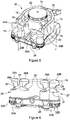
Figure 5 shows a perspective view of a roller pump with a clamp system in accordance with an embodiment of the present invention; -
Figure 6 shows a front view of a clamp system in accordance with the embodiment offigure 5 ; -
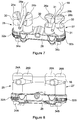
Figure 7 shows a perspective view of a clamp system in use in accordance with the embodiment offigure 5 ; -
Figure 8 shows a front view of a clamp system with a larger tube diameter in accordance with the embodiment offigure 5 . - With reference to
Figure 5 , there is shown aroller pump 10 comprising ahousing 12, arotor 14 androllers 16. Therotor 14 is located within thehousing 12 and aflexible tube 18 is fed around therotor 14, between therotor 14 and thehousing 12. Therotor 14 is substantially cylindrical and extends longitudinally which, for ease of description, shall be called the vertical direction. Thehousing 12 has extending vertical walls being substantially parallel to the longitudinal sides of therotor 14. Thetube 18 is located around thehousing 12 at approximately the vertical mid-point of thehousing 12.Arms 20 connected to therotor 14 are used to locate thetube 18 in position. Thehousing 12 comprises a part-circular portion 22 which follows the curvature of therotor 14 and thus maintains an approximate same distance between the inner walls of thehousing 12 and the sides of therotor 14. This allows therollers 16 to also maintain an approximate same distance to the inner walls of thehousing 12 which enables therotor 14 androllers 16 to make a relatively consistent compression of theflexible tube 18 as they rotate. - Where the
tube 18 enters and exits theroller pump 10, there is provided two pairs ofbobbins bobbins bobbins tube 18 passes through anopening 28A formed from a pair of substantially semi-circular slots orgrooves 30, one in each of the first pair ofbobbins grooves 30 have a semi-circular cross section. This will conventionally be called the entry, i.e. the direction of the fluid, e.g. blood, is towards theroller pump 10 at this point when it is being pumped. Thetube 18 also passes through a similar opening 28B in the second pair ofbobbins roller pump 10 at this point when it is being pumped. The pair ofbobbins LHS clamp 25 and the pair ofbobbins RHS clamp 27. The clamps 25, 27, work to hold thetube 18 in place, which will be described in more detail later. - The current embodiment has two pairs of
bobbins tube 18 "walking" around theroller pump 10 and being stretched out of thehousing 12. This also means that the fluid flow can be reversed in thetube 18 and thetube 18 would still be held in theroller pump 10. However, in other embodiments, only one pair of bobbins may be used to clamp thetube 18. - The
bobbins bobbins housing 12. Thebobbins roller pump 10. The twobobbins bobbins - The
grooves 30 in thebobbins tube 18 sizes to be accommodated. The profiles are shown inFigures 6 and7 such that thesemi-circular grooves 30 have steadily decreasing diameters formed around the circumference of thebobbins bobbins semi-circular groove 30 decreasing from the largest diameter to the smallest diameter in a clockwise direction. When viewed from above, thebobbins semi-circular groove 30 decreasing from the largest diameter to the smallest diameter in an anticlockwise direction. - The
bobbins bobbins opening 28A formed by thegrooves 30 is always circular. The situation is the same forbobbins - There is a smaller portion of the circumference of the
bobbins semi-circular groove 30 has the largest diameter and where thesemi-circular groove 30 has smallest diameter, where there is not a steady change in size but a discontinuity. This discontinuity is in the form of aflatter section 31 located nearer the full diameter of thebobbins - The mount 32 comprises
sprockets bobbins bobbins bobbins tube 18 tightly and the locking handles 34A, 34B can be turned to lock or release thebobbins tube 18 has been clamped tight enough which then automatically locks the bobbins. - The
tube 18 must be held at the entry and exit points otherwise as therotor 14 turns and therollers 16 compresses thetube 18 to pump the fluid, thetube 18 will move, or "walk" around thehousing 12 which is undesirable. This could lead to thetube 18 being pulled out of accompanying components or cause a blockage in thetube 18. The current invention overcomes some of the limitations of prior art clamps used in roller pumps and provides an improved system. - Referring now to
Figure 7 , it is shown that thetube 18 can be introduced throughopenings 28A, 28B between the correspondingbobbins bobbins LHS clamp 25, they are shown in their fully open position, i.e. where thesemi-circular groove 30 are directly facing each other at their largest diameter. This gives the largest spacing between the twobobbins bobbins bobbin 24B is fully rotated clockwise. As thebobbins semi-circular groove 30 facing each other. In other embodiments, thebobbins tubes 18 as the outer diameters of thetubes 18 are small enough to fit intosmaller openings 28A, 28B, between thebobbins - Once the
tube 18 is located centrally between thebobbins bobbin 24B is rotated anticlockwise. This rotation, and the shape of the profiles of thebobbins opening 28A reduces in effective diameter. A locking mechanism in the form of an anti-rotation ratchet (not shown) is provided to prevent thebobbins tube 18 being released. The locking handle 34A must be released to allow thebobbins tube 18. In other embodiments, once thetube 18 is gripped by thecircular opening 28A, i.e. clamped between the twobobbins locking handle 34A. TheRHS clamp 27 shows thetube 18 clamped in place. It can be seen that thebobbins circular opening 28A between thebobbins tube 18 in position. In this case, thebobbins groove 30 face each other. Instead, they have been stopped using the locking mechanism as the optimum position for holding thetube 18 without undue deformation has been reached. This is in contrast to the prior art roller tube grippers ofFigure 2 which can be seen to visibly deform the tube. -
Figure 8 shows alarger diameter tube 18 being clamped following the same procedure as described in relation toFigure 7 . This illustrates that differentsized tubes 18 can be accommodated without unduly deforming them or having to modify the clamps by adding and removing pieces specific to the tube sizes. - When the
roller pump 10 is operated therollers 16 will place thetube 18 in tension and try to pull it through the bobbin clamps 25, 27. This will draw theclamps tube 18 and resist movement of thetube 18. This is because, the orientation of thebobbins tube 10 acting to move thetube 18 further into theroller pump 10 from the entry point rotates thebobbin 24A anticlockwise and thebobbin 24B clockwise which makes theopening 28A between thebobbins tube 18 is always clamped in acircular opening 28A, thetube 18 will not be pinched, as can occur in prior art clamping arrangements. The situation is similar forclamp 27, however it is tension acting to move thetube 18 further into theroller pump 14 from the exit point of theroller pump 14 that provides the rotation of thebobbins bobbins bobbins larger opening 28A, 28B. - It is clear from the above description that the current invention provides a system which is capable of fitting a wide variety of tube diameters without unduly restricting flow, and causing excessive degradation of the flexible tubes. Also, the system can quickly be changed to accommodate different sizes of tubes without having to add or remove pieces, which reduces time and associated cost.
- It will be appreciated by persons skilled in the art that various modifications may be made to the above embodiment without departing from the scope of the present invention as defined by the claims. For example, whilst the above discussion has been concerned with pumping blood around a tube for use in a surgical procedure, the invention is equally applicable pumping other fluids such as slurries, chemicals or dangerous substances.
- In addition, while the above discussion has described the more likely case of circular tubes, non-circular tubes may also be used in embodiments of the invention. For example, oval shaped tubes may be used and the grooves of the bobbins may be shaped so as to accommodate the oval tubes and perform a similar retaining function as that described above.
Claims (11)
- A clamp arrangement for retaining a flexible tube (18) during operation of a roller pump (10) for pumping fluid, the clamp arrangement comprising:a pair of rotatable bobbins (24A, 24B) mounted adjacent to each other;wherein each bobbin has a tapered groove (30), formed partially around a cylindrical surface of the bobbin, with its groove diameter steadily decreasing from a largest diameter to a smallest diameter, and wherein one of the bobbins has the tapered groove (30) tapering in a clockwise direction and the other bobbin has the tapered groove (30) tapering in an anticlockwise direction;whereby counter rotation of the bobbins (24A, 24B) clamps the tube (18) between the bobbins (24A, 24B) in the tapered grooves (30).
- The clamp arrangement according to claim 1, wherein, the cross sectional size of the tapered groove of one bobbin matches the cross sectional size of the tapered groove of the other bobbin.
- The clamp arrangement according to claim 1 or 2, wherein the tapered grooves of each of the bobbins have a semi-circular cross section.
- The clamp arrangement according to claim 3, wherein the diameter of the tapered groove of one bobbin matches the diameter of the tapered groove of the other bobbin.
- The clamp arrangement according to any preceding claim, wherein the bobbins are configured to counter rotate at the same rate to steadily reduce the size of the opening.
- The clamp arrangement according to any preceding claim, further comprising a locking mechanism configured to stop the rotation of the bobbins in the direction which enlarges the opening.
- The clamp arrangement according to claim 6, wherein the locking mechanism comprises a ratchet or a locking handle.
- The clamp arrangement according to any preceding claim, wherein the bobbins are configured to tighten around the tube when the tube is under tension from the roller pump.
- The clamp arrangement according to any preceding claim, further comprising another pair of said bobbins.
- The clamp arrangement according to claim 9, wherein the tube passes through one pair of bobbins before entering a housing of the roller pump and passes through the other pair of bobbins upon exiting the housing.
- A roller pump for pumping fluid around a flexible tube comprising:
a clamp arrangement as provided in any preceding claim.
Applications Claiming Priority (2)
| Application Number | Priority Date | Filing Date | Title |
|---|---|---|---|
| GB1500422.9A GB2537340B (en) | 2015-01-12 | 2015-01-12 | Pump tube retention mechanism |
| PCT/GB2016/050044 WO2016113545A1 (en) | 2015-01-12 | 2016-01-08 | Pump tube retention mechanism |
Publications (2)
| Publication Number | Publication Date |
|---|---|
| EP3244963A1 EP3244963A1 (en) | 2017-11-22 |
| EP3244963B1 true EP3244963B1 (en) | 2018-12-26 |
Family
ID=52597473
Family Applications (1)
| Application Number | Title | Priority Date | Filing Date |
|---|---|---|---|
| EP16700513.1A Active EP3244963B1 (en) | 2015-01-12 | 2016-01-08 | Pump tube retention mechanism |
Country Status (6)
| Country | Link |
|---|---|
| US (1) | US10773071B2 (en) |
| EP (1) | EP3244963B1 (en) |
| JP (1) | JP2018501432A (en) |
| CN (1) | CN107206226B (en) |
| GB (1) | GB2537340B (en) |
| WO (1) | WO2016113545A1 (en) |
Families Citing this family (12)
| Publication number | Priority date | Publication date | Assignee | Title |
|---|---|---|---|---|
| GB2547900B (en) | 2016-03-01 | 2018-03-28 | Spectrum Medical Ltd | Flow control system |
| JP7053630B2 (en) | 2016-09-22 | 2022-04-12 | クリストファー, ジェイ プロット, | Equipment and methods for in vitro conditioning of blood |
| GB2570320A (en) * | 2018-01-19 | 2019-07-24 | Watson Marlow Ltd | Peristaltic rotor unit, clamp and tube connector |
| US11338288B2 (en) * | 2018-10-01 | 2022-05-24 | Boehringer Ingelheim Vetmedica Gmbh | Peristaltic pump and analyzer for testing a sample |
| EP3884161B1 (en) * | 2018-11-20 | 2026-04-15 | LivaNova Deutschland GmbH | Tube retention device for a roller pump head |
| CN110307348B (en) * | 2019-07-01 | 2020-09-11 | 陕西理工大学 | A kind of electric fluid flow regulating device and regulating method |
| CN110296234B (en) * | 2019-07-01 | 2020-06-26 | 陕西理工大学 | Complex flow path state control device and control method thereof |
| CN110332338B (en) * | 2019-07-01 | 2020-10-16 | 陕西理工大学 | Flow path proportion adjusting device and adjusting method thereof |
| CN112343805A (en) * | 2020-11-26 | 2021-02-09 | 保定准择恒流泵制造有限公司 | Hose fixing structure and peristaltic pump comprising same |
| CN115507001B (en) * | 2022-09-28 | 2023-08-22 | 无锡市天利流体科技有限公司 | Peristaltic pump with adjustable tube pressing gap |
| CN115737967A (en) * | 2022-12-05 | 2023-03-07 | 武汉迈瑞医疗技术研究院有限公司 | Filling pump |
| CN118517402B (en) * | 2024-05-28 | 2024-11-08 | 深圳市德宇鑫科技有限公司 | Peristaltic pump capable of finely adjusting flow |
Family Cites Families (19)
| Publication number | Priority date | Publication date | Assignee | Title |
|---|---|---|---|---|
| GB467288A (en) * | 1936-02-14 | 1937-06-15 | Cyril George Mancha Bennett | Improvements in and relating to pumps |
| US2197310A (en) * | 1939-03-17 | 1940-04-16 | Hawley W Lincoln | Clamping device |
| US4164223A (en) * | 1977-08-04 | 1979-08-14 | Munib Hamza I | Surgical instrument |
| US4179249A (en) | 1977-12-07 | 1979-12-18 | Cole-Parmer Instrument Company | Quick loading peristaltic pump |
| JPS59176481A (en) * | 1983-03-24 | 1984-10-05 | Shin Meiwa Ind Co Ltd | elastic tube pump |
| JP4557452B2 (en) * | 2001-03-13 | 2010-10-06 | 日本電産サーボ株式会社 | Roller pump |
| US20040267305A1 (en) * | 2003-06-30 | 2004-12-30 | Borgman Mark H. | Flexible tube contents remover |
| FR2859507B1 (en) * | 2003-09-08 | 2006-02-17 | Athena Innovations | PERISTALTIC PUMP WITH DEFORMABLE REMOVABLE RACK |
| US6957798B1 (en) * | 2004-01-20 | 2005-10-25 | Schmidt Edward A | Pinch valve |
| CA2557915A1 (en) * | 2004-03-04 | 2005-03-22 | Cole-Parmer Instrument Company | Peristaltic pump |
| US7322556B2 (en) * | 2005-09-08 | 2008-01-29 | Bernstein Robert E | Pinch valve for regulating fluid flow |
| US7565918B2 (en) * | 2006-07-14 | 2009-07-28 | Johnson Controls Technology Company | Variable orifice rotary control valve |
| US20110314977A1 (en) * | 2008-01-08 | 2011-12-29 | Lewis Howell G | Tube purging instrument |
| US9044544B2 (en) * | 2008-11-21 | 2015-06-02 | Baxter International Inc. | Dialysis machine having auto-connection system with roller occluder |
| US10113542B2 (en) * | 2012-05-24 | 2018-10-30 | Cook Medical Technologies Llc | Peristaltic pump tubing securing system |
| KR101266756B1 (en) | 2012-06-20 | 2013-05-28 | 김동식 | Iv flow controller with flushing feature |
| CH707421A1 (en) | 2012-12-19 | 2014-06-30 | Suisse Electronique Microtech | Throttling valve for controlling e.g. direction of gas in field of micromechanics for controlling irrigation water, has reduced friction element that is assembled jointly with case and is intercalated between cam wheel and flexible tube |
| WO2016061194A1 (en) * | 2014-10-15 | 2016-04-21 | Covidien Lp | Occlusion detection for flow control apparatus |
| GB2564115A (en) * | 2017-07-03 | 2019-01-09 | Spectrum Medical Ltd | Indicator device and system |
-
2015
- 2015-01-12 GB GB1500422.9A patent/GB2537340B/en active Active
-
2016
- 2016-01-08 WO PCT/GB2016/050044 patent/WO2016113545A1/en not_active Ceased
- 2016-01-08 JP JP2017536553A patent/JP2018501432A/en active Pending
- 2016-01-08 CN CN201680005589.1A patent/CN107206226B/en active Active
- 2016-01-08 US US15/542,235 patent/US10773071B2/en active Active
- 2016-01-08 EP EP16700513.1A patent/EP3244963B1/en active Active
Non-Patent Citations (1)
| Title |
|---|
| None * |
Also Published As
| Publication number | Publication date |
|---|---|
| WO2016113545A1 (en) | 2016-07-21 |
| JP2018501432A (en) | 2018-01-18 |
| EP3244963A1 (en) | 2017-11-22 |
| CN107206226B (en) | 2021-01-22 |
| US10773071B2 (en) | 2020-09-15 |
| GB2537340A (en) | 2016-10-19 |
| CN107206226A (en) | 2017-09-26 |
| GB2537340B (en) | 2017-08-23 |
| US20170354814A1 (en) | 2017-12-14 |
| GB201500422D0 (en) | 2015-02-25 |
Similar Documents
| Publication | Publication Date | Title |
|---|---|---|
| US10773071B2 (en) | Pump tube retention mechanism | |
| EP1309281B1 (en) | Gripping devices | |
| TWI865909B (en) | Portable film packing apparatus | |
| US20100005655A1 (en) | Tubing installation tool for a peristaltic pump and methods of use | |
| US9719750B2 (en) | Universal archery bow press | |
| EP2711564A2 (en) | Quick release clamp | |
| EP3232059B1 (en) | Hose pump | |
| TWI644022B (en) | A peristaltic pump | |
| JP2005509119A (en) | Clamp | |
| US10646980B2 (en) | Luer lock tools and methods of assembling a luer lock fitting | |
| US20110284776A1 (en) | Pinching closed a collapsible tube for biopharmaceutical use | |
| TR201815831T4 (en) | TAPING APPARATUS | |
| NO762264L (en) | ||
| US20110314977A1 (en) | Tube purging instrument | |
| US9567993B2 (en) | System and method for holding tubing for a peristaltic pump | |
| US20080163731A1 (en) | Tube purging instrument | |
| US9879813B2 (en) | Pinching device for temporarily closing flexible tubing | |
| CA3095072C (en) | Needleless connector loosening device | |
| WO2007005902A2 (en) | Syringe clip | |
| CN209604732U (en) | A kind of peristaltic pump hose fixing device | |
| CN222426932U (en) | Dialysis pipeline fixing device | |
| BR202012009084U2 (en) | manual pull pliers | |
| FR2995050A1 (en) | Device for tightening and loosening e.g. cables, has cable traversing device when all circular end openings are aligned, and spiral exerting shear on cable to maintain cable in locked state when user exerts pressure on body of part | |
| WO2013169892A1 (en) | Hose clamp with roller and locking tab | |
| ITUB20155959A1 (en) | blood treatment equipment and peristaltic pump |
Legal Events
| Date | Code | Title | Description |
|---|---|---|---|
| STAA | Information on the status of an ep patent application or granted ep patent |
Free format text: STATUS: THE INTERNATIONAL PUBLICATION HAS BEEN MADE |
|
| PUAI | Public reference made under article 153(3) epc to a published international application that has entered the european phase |
Free format text: ORIGINAL CODE: 0009012 |
|
| STAA | Information on the status of an ep patent application or granted ep patent |
Free format text: STATUS: REQUEST FOR EXAMINATION WAS MADE |
|
| 17P | Request for examination filed |
Effective date: 20170727 |
|
| AK | Designated contracting states |
Kind code of ref document: A1 Designated state(s): AL AT BE BG CH CY CZ DE DK EE ES FI FR GB GR HR HU IE IS IT LI LT LU LV MC MK MT NL NO PL PT RO RS SE SI SK SM TR |
|
| AX | Request for extension of the european patent |
Extension state: BA ME |
|
| DAV | Request for validation of the european patent (deleted) | ||
| DAX | Request for extension of the european patent (deleted) | ||
| GRAP | Despatch of communication of intention to grant a patent |
Free format text: ORIGINAL CODE: EPIDOSNIGR1 |
|
| STAA | Information on the status of an ep patent application or granted ep patent |
Free format text: STATUS: GRANT OF PATENT IS INTENDED |
|
| INTG | Intention to grant announced |
Effective date: 20180606 |
|
| GRAJ | Information related to disapproval of communication of intention to grant by the applicant or resumption of examination proceedings by the epo deleted |
Free format text: ORIGINAL CODE: EPIDOSDIGR1 |
|
| STAA | Information on the status of an ep patent application or granted ep patent |
Free format text: STATUS: REQUEST FOR EXAMINATION WAS MADE |
|
| RBV | Designated contracting states (corrected) |
Designated state(s): AL AT BE BG CH CY CZ DE DK EE ES FI FR GR HR HU IE IS IT LI LT LU LV MC MK MT NL NO PL PT RO RS SE SI SK SM TR |
|
| INTC | Intention to grant announced (deleted) | ||
| GRAR | Information related to intention to grant a patent recorded |
Free format text: ORIGINAL CODE: EPIDOSNIGR71 |
|
| GRAS | Grant fee paid |
Free format text: ORIGINAL CODE: EPIDOSNIGR3 |
|
| STAA | Information on the status of an ep patent application or granted ep patent |
Free format text: STATUS: GRANT OF PATENT IS INTENDED |
|
| GRAA | (expected) grant |
Free format text: ORIGINAL CODE: 0009210 |
|
| STAA | Information on the status of an ep patent application or granted ep patent |
Free format text: STATUS: THE PATENT HAS BEEN GRANTED |
|
| INTG | Intention to grant announced |
Effective date: 20181115 |
|
| AK | Designated contracting states |
Kind code of ref document: B1 Designated state(s): AL AT BE BG CH CY CZ DE DK EE ES FI FR GR HR HU IE IS IT LI LT LU LV MC MK MT NL NO PL PT RO RS SE SI SK SM TR |
|
| REG | Reference to a national code |
Ref country code: CH Ref legal event code: EP |
|
| REG | Reference to a national code |
Ref country code: AT Ref legal event code: REF Ref document number: 1080574 Country of ref document: AT Kind code of ref document: T Effective date: 20190115 |
|
| REG | Reference to a national code |
Ref country code: DE Ref legal event code: R096 Ref document number: 602016008689 Country of ref document: DE |
|
| REG | Reference to a national code |
Ref country code: IE Ref legal event code: FG4D |
|
| PG25 | Lapsed in a contracting state [announced via postgrant information from national office to epo] |
Ref country code: LV Free format text: LAPSE BECAUSE OF FAILURE TO SUBMIT A TRANSLATION OF THE DESCRIPTION OR TO PAY THE FEE WITHIN THE PRESCRIBED TIME-LIMIT Effective date: 20181226 Ref country code: FI Free format text: LAPSE BECAUSE OF FAILURE TO SUBMIT A TRANSLATION OF THE DESCRIPTION OR TO PAY THE FEE WITHIN THE PRESCRIBED TIME-LIMIT Effective date: 20181226 Ref country code: NO Free format text: LAPSE BECAUSE OF FAILURE TO SUBMIT A TRANSLATION OF THE DESCRIPTION OR TO PAY THE FEE WITHIN THE PRESCRIBED TIME-LIMIT Effective date: 20190326 Ref country code: LT Free format text: LAPSE BECAUSE OF FAILURE TO SUBMIT A TRANSLATION OF THE DESCRIPTION OR TO PAY THE FEE WITHIN THE PRESCRIBED TIME-LIMIT Effective date: 20181226 Ref country code: HR Free format text: LAPSE BECAUSE OF FAILURE TO SUBMIT A TRANSLATION OF THE DESCRIPTION OR TO PAY THE FEE WITHIN THE PRESCRIBED TIME-LIMIT Effective date: 20181226 Ref country code: BG Free format text: LAPSE BECAUSE OF FAILURE TO SUBMIT A TRANSLATION OF THE DESCRIPTION OR TO PAY THE FEE WITHIN THE PRESCRIBED TIME-LIMIT Effective date: 20190326 |
|
| REG | Reference to a national code |
Ref country code: NL Ref legal event code: MP Effective date: 20181226 |
|
| REG | Reference to a national code |
Ref country code: LT Ref legal event code: MG4D |
|
| PG25 | Lapsed in a contracting state [announced via postgrant information from national office to epo] |
Ref country code: GR Free format text: LAPSE BECAUSE OF FAILURE TO SUBMIT A TRANSLATION OF THE DESCRIPTION OR TO PAY THE FEE WITHIN THE PRESCRIBED TIME-LIMIT Effective date: 20190327 Ref country code: SE Free format text: LAPSE BECAUSE OF FAILURE TO SUBMIT A TRANSLATION OF THE DESCRIPTION OR TO PAY THE FEE WITHIN THE PRESCRIBED TIME-LIMIT Effective date: 20181226 Ref country code: AL Free format text: LAPSE BECAUSE OF FAILURE TO SUBMIT A TRANSLATION OF THE DESCRIPTION OR TO PAY THE FEE WITHIN THE PRESCRIBED TIME-LIMIT Effective date: 20181226 Ref country code: RS Free format text: LAPSE BECAUSE OF FAILURE TO SUBMIT A TRANSLATION OF THE DESCRIPTION OR TO PAY THE FEE WITHIN THE PRESCRIBED TIME-LIMIT Effective date: 20181226 |
|
| REG | Reference to a national code |
Ref country code: AT Ref legal event code: MK05 Ref document number: 1080574 Country of ref document: AT Kind code of ref document: T Effective date: 20181226 |
|
| PG25 | Lapsed in a contracting state [announced via postgrant information from national office to epo] |
Ref country code: NL Free format text: LAPSE BECAUSE OF FAILURE TO SUBMIT A TRANSLATION OF THE DESCRIPTION OR TO PAY THE FEE WITHIN THE PRESCRIBED TIME-LIMIT Effective date: 20181226 |
|
| PG25 | Lapsed in a contracting state [announced via postgrant information from national office to epo] |
Ref country code: ES Free format text: LAPSE BECAUSE OF FAILURE TO SUBMIT A TRANSLATION OF THE DESCRIPTION OR TO PAY THE FEE WITHIN THE PRESCRIBED TIME-LIMIT Effective date: 20181226 Ref country code: PT Free format text: LAPSE BECAUSE OF FAILURE TO SUBMIT A TRANSLATION OF THE DESCRIPTION OR TO PAY THE FEE WITHIN THE PRESCRIBED TIME-LIMIT Effective date: 20190426 Ref country code: CZ Free format text: LAPSE BECAUSE OF FAILURE TO SUBMIT A TRANSLATION OF THE DESCRIPTION OR TO PAY THE FEE WITHIN THE PRESCRIBED TIME-LIMIT Effective date: 20181226 Ref country code: PL Free format text: LAPSE BECAUSE OF FAILURE TO SUBMIT A TRANSLATION OF THE DESCRIPTION OR TO PAY THE FEE WITHIN THE PRESCRIBED TIME-LIMIT Effective date: 20181226 |
|
| PG25 | Lapsed in a contracting state [announced via postgrant information from national office to epo] |
Ref country code: IS Free format text: LAPSE BECAUSE OF FAILURE TO SUBMIT A TRANSLATION OF THE DESCRIPTION OR TO PAY THE FEE WITHIN THE PRESCRIBED TIME-LIMIT Effective date: 20190426 Ref country code: SK Free format text: LAPSE BECAUSE OF FAILURE TO SUBMIT A TRANSLATION OF THE DESCRIPTION OR TO PAY THE FEE WITHIN THE PRESCRIBED TIME-LIMIT Effective date: 20181226 Ref country code: RO Free format text: LAPSE BECAUSE OF FAILURE TO SUBMIT A TRANSLATION OF THE DESCRIPTION OR TO PAY THE FEE WITHIN THE PRESCRIBED TIME-LIMIT Effective date: 20181226 Ref country code: EE Free format text: LAPSE BECAUSE OF FAILURE TO SUBMIT A TRANSLATION OF THE DESCRIPTION OR TO PAY THE FEE WITHIN THE PRESCRIBED TIME-LIMIT Effective date: 20181226 Ref country code: SM Free format text: LAPSE BECAUSE OF FAILURE TO SUBMIT A TRANSLATION OF THE DESCRIPTION OR TO PAY THE FEE WITHIN THE PRESCRIBED TIME-LIMIT Effective date: 20181226 |
|
| REG | Reference to a national code |
Ref country code: CH Ref legal event code: PL |
|
| REG | Reference to a national code |
Ref country code: DE Ref legal event code: R097 Ref document number: 602016008689 Country of ref document: DE |
|
| PG25 | Lapsed in a contracting state [announced via postgrant information from national office to epo] |
Ref country code: LU Free format text: LAPSE BECAUSE OF NON-PAYMENT OF DUE FEES Effective date: 20190108 |
|
| REG | Reference to a national code |
Ref country code: BE Ref legal event code: MM Effective date: 20190131 |
|
| REG | Reference to a national code |
Ref country code: IE Ref legal event code: MM4A |
|
| PG25 | Lapsed in a contracting state [announced via postgrant information from national office to epo] |
Ref country code: MC Free format text: LAPSE BECAUSE OF FAILURE TO SUBMIT A TRANSLATION OF THE DESCRIPTION OR TO PAY THE FEE WITHIN THE PRESCRIBED TIME-LIMIT Effective date: 20181226 Ref country code: AT Free format text: LAPSE BECAUSE OF FAILURE TO SUBMIT A TRANSLATION OF THE DESCRIPTION OR TO PAY THE FEE WITHIN THE PRESCRIBED TIME-LIMIT Effective date: 20181226 Ref country code: DK Free format text: LAPSE BECAUSE OF FAILURE TO SUBMIT A TRANSLATION OF THE DESCRIPTION OR TO PAY THE FEE WITHIN THE PRESCRIBED TIME-LIMIT Effective date: 20181226 |
|
| PLBE | No opposition filed within time limit |
Free format text: ORIGINAL CODE: 0009261 |
|
| STAA | Information on the status of an ep patent application or granted ep patent |
Free format text: STATUS: NO OPPOSITION FILED WITHIN TIME LIMIT |
|
| PG25 | Lapsed in a contracting state [announced via postgrant information from national office to epo] |
Ref country code: BE Free format text: LAPSE BECAUSE OF NON-PAYMENT OF DUE FEES Effective date: 20190131 |
|
| 26N | No opposition filed |
Effective date: 20190927 |
|
| PG25 | Lapsed in a contracting state [announced via postgrant information from national office to epo] |
Ref country code: CH Free format text: LAPSE BECAUSE OF NON-PAYMENT OF DUE FEES Effective date: 20190131 Ref country code: LI Free format text: LAPSE BECAUSE OF NON-PAYMENT OF DUE FEES Effective date: 20190131 |
|
| PG25 | Lapsed in a contracting state [announced via postgrant information from national office to epo] |
Ref country code: IE Free format text: LAPSE BECAUSE OF NON-PAYMENT OF DUE FEES Effective date: 20190108 |
|
| PG25 | Lapsed in a contracting state [announced via postgrant information from national office to epo] |
Ref country code: SI Free format text: LAPSE BECAUSE OF FAILURE TO SUBMIT A TRANSLATION OF THE DESCRIPTION OR TO PAY THE FEE WITHIN THE PRESCRIBED TIME-LIMIT Effective date: 20181226 |
|
| PG25 | Lapsed in a contracting state [announced via postgrant information from national office to epo] |
Ref country code: TR Free format text: LAPSE BECAUSE OF FAILURE TO SUBMIT A TRANSLATION OF THE DESCRIPTION OR TO PAY THE FEE WITHIN THE PRESCRIBED TIME-LIMIT Effective date: 20181226 |
|
| PG25 | Lapsed in a contracting state [announced via postgrant information from national office to epo] |
Ref country code: MT Free format text: LAPSE BECAUSE OF NON-PAYMENT OF DUE FEES Effective date: 20190108 |
|
| PG25 | Lapsed in a contracting state [announced via postgrant information from national office to epo] |
Ref country code: CY Free format text: LAPSE BECAUSE OF FAILURE TO SUBMIT A TRANSLATION OF THE DESCRIPTION OR TO PAY THE FEE WITHIN THE PRESCRIBED TIME-LIMIT Effective date: 20181226 |
|
| PG25 | Lapsed in a contracting state [announced via postgrant information from national office to epo] |
Ref country code: HU Free format text: LAPSE BECAUSE OF FAILURE TO SUBMIT A TRANSLATION OF THE DESCRIPTION OR TO PAY THE FEE WITHIN THE PRESCRIBED TIME-LIMIT; INVALID AB INITIO Effective date: 20160108 |
|
| PG25 | Lapsed in a contracting state [announced via postgrant information from national office to epo] |
Ref country code: MK Free format text: LAPSE BECAUSE OF FAILURE TO SUBMIT A TRANSLATION OF THE DESCRIPTION OR TO PAY THE FEE WITHIN THE PRESCRIBED TIME-LIMIT Effective date: 20181226 |
|
| P01 | Opt-out of the competence of the unified patent court (upc) registered |
Effective date: 20230505 |
|
| PGFP | Annual fee paid to national office [announced via postgrant information from national office to epo] |
Ref country code: FR Payment date: 20251222 Year of fee payment: 11 |
|
| PGFP | Annual fee paid to national office [announced via postgrant information from national office to epo] |
Ref country code: DE Payment date: 20251224 Year of fee payment: 11 |
|
| PGFP | Annual fee paid to national office [announced via postgrant information from national office to epo] |
Ref country code: IT Payment date: 20251230 Year of fee payment: 11 |