EP3244823B1 - Device for accommodating surgical tool prior to and during medical procedures - Google Patents
Device for accommodating surgical tool prior to and during medical procedures Download PDFInfo
- Publication number
- EP3244823B1 EP3244823B1 EP16737858.7A EP16737858A EP3244823B1 EP 3244823 B1 EP3244823 B1 EP 3244823B1 EP 16737858 A EP16737858 A EP 16737858A EP 3244823 B1 EP3244823 B1 EP 3244823B1
- Authority
- EP
- European Patent Office
- Prior art keywords
- opening
- sealing
- housing
- battery
- canal
- Prior art date
- Legal status (The legal status is an assumption and is not a legal conclusion. Google has not performed a legal analysis and makes no representation as to the accuracy of the status listed.)
- Active
Links
- 238000000034 method Methods 0.000 title description 3
- 238000007789 sealing Methods 0.000 claims description 65
- 239000000463 material Substances 0.000 claims description 40
- 239000007788 liquid Substances 0.000 claims description 23
- 238000010438 heat treatment Methods 0.000 claims description 15
- 239000013536 elastomeric material Substances 0.000 claims description 2
- 239000012925 reference material Substances 0.000 description 18
- 238000004140 cleaning Methods 0.000 description 13
- 239000004033 plastic Substances 0.000 description 10
- 229920003023 plastic Polymers 0.000 description 10
- 229920001410 Microfiber Polymers 0.000 description 7
- 239000003658 microfiber Substances 0.000 description 7
- 239000000853 adhesive Substances 0.000 description 6
- 230000001070 adhesive effect Effects 0.000 description 6
- 229910052782 aluminium Inorganic materials 0.000 description 5
- XAGFODPZIPBFFR-UHFFFAOYSA-N aluminium Chemical compound [Al] XAGFODPZIPBFFR-UHFFFAOYSA-N 0.000 description 5
- 239000006260 foam Substances 0.000 description 5
- 239000000499 gel Substances 0.000 description 5
- 238000001356 surgical procedure Methods 0.000 description 5
- XLYOFNOQVPJJNP-UHFFFAOYSA-N water Substances O XLYOFNOQVPJJNP-UHFFFAOYSA-N 0.000 description 5
- 239000004744 fabric Substances 0.000 description 4
- 230000036512 infertility Effects 0.000 description 4
- 229910001220 stainless steel Inorganic materials 0.000 description 4
- 239000010935 stainless steel Substances 0.000 description 4
- 230000006378 damage Effects 0.000 description 3
- 238000010586 diagram Methods 0.000 description 3
- 239000012530 fluid Substances 0.000 description 3
- 230000001681 protective effect Effects 0.000 description 3
- 241000272525 Anas platyrhynchos Species 0.000 description 2
- LFQSCWFLJHTTHZ-UHFFFAOYSA-N Ethanol Chemical compound CCO LFQSCWFLJHTTHZ-UHFFFAOYSA-N 0.000 description 2
- LYCAIKOWRPUZTN-UHFFFAOYSA-N Ethylene glycol Chemical compound OCCO LYCAIKOWRPUZTN-UHFFFAOYSA-N 0.000 description 2
- 229920005830 Polyurethane Foam Polymers 0.000 description 2
- 239000011111 cardboard Substances 0.000 description 2
- 238000004891 communication Methods 0.000 description 2
- 230000001419 dependent effect Effects 0.000 description 2
- 230000005611 electricity Effects 0.000 description 2
- 229920001821 foam rubber Polymers 0.000 description 2
- 239000003349 gelling agent Substances 0.000 description 2
- 239000004619 high density foam Substances 0.000 description 2
- 229920002529 medical grade silicone Polymers 0.000 description 2
- 229910052751 metal Inorganic materials 0.000 description 2
- 239000002184 metal Substances 0.000 description 2
- 229920001296 polysiloxane Polymers 0.000 description 2
- 239000011496 polyurethane foam Substances 0.000 description 2
- 230000035939 shock Effects 0.000 description 2
- 239000004094 surface-active agent Substances 0.000 description 2
- 238000012546 transfer Methods 0.000 description 2
- RYGMFSIKBFXOCR-UHFFFAOYSA-N Copper Chemical compound [Cu] RYGMFSIKBFXOCR-UHFFFAOYSA-N 0.000 description 1
- CTKXFMQHOOWWEB-UHFFFAOYSA-N Ethylene oxide/propylene oxide copolymer Chemical compound CCCOC(C)COCCO CTKXFMQHOOWWEB-UHFFFAOYSA-N 0.000 description 1
- 239000004677 Nylon Substances 0.000 description 1
- 229920002472 Starch Polymers 0.000 description 1
- 230000002745 absorbent Effects 0.000 description 1
- 239000002250 absorbent Substances 0.000 description 1
- 230000004913 activation Effects 0.000 description 1
- 238000013459 approach Methods 0.000 description 1
- 230000004888 barrier function Effects 0.000 description 1
- 210000001124 body fluid Anatomy 0.000 description 1
- 230000036760 body temperature Effects 0.000 description 1
- 239000012459 cleaning agent Substances 0.000 description 1
- 239000011248 coating agent Substances 0.000 description 1
- 238000000576 coating method Methods 0.000 description 1
- 239000003086 colorant Substances 0.000 description 1
- 239000012141 concentrate Substances 0.000 description 1
- 230000000994 depressogenic effect Effects 0.000 description 1
- 230000001627 detrimental effect Effects 0.000 description 1
- 239000003814 drug Substances 0.000 description 1
- 229940079593 drug Drugs 0.000 description 1
- 238000012377 drug delivery Methods 0.000 description 1
- 230000009977 dual effect Effects 0.000 description 1
- 239000006261 foam material Substances 0.000 description 1
- 210000003709 heart valve Anatomy 0.000 description 1
- 230000002209 hydrophobic effect Effects 0.000 description 1
- WGCNASOHLSPBMP-UHFFFAOYSA-N hydroxyacetaldehyde Natural products OCC=O WGCNASOHLSPBMP-UHFFFAOYSA-N 0.000 description 1
- 238000007373 indentation Methods 0.000 description 1
- 238000003780 insertion Methods 0.000 description 1
- 239000011810 insulating material Substances 0.000 description 1
- 239000004620 low density foam Substances 0.000 description 1
- 230000005389 magnetism Effects 0.000 description 1
- 239000000203 mixture Substances 0.000 description 1
- 229910001120 nichrome Inorganic materials 0.000 description 1
- 239000002736 nonionic surfactant Substances 0.000 description 1
- 229920001778 nylon Polymers 0.000 description 1
- 239000003973 paint Substances 0.000 description 1
- 230000000737 periodic effect Effects 0.000 description 1
- 229920001993 poloxamer 188 Polymers 0.000 description 1
- 229940044519 poloxamer 188 Drugs 0.000 description 1
- 229920000728 polyester Polymers 0.000 description 1
- 229920002635 polyurethane Polymers 0.000 description 1
- 239000004814 polyurethane Substances 0.000 description 1
- 230000000284 resting effect Effects 0.000 description 1
- 229910052710 silicon Inorganic materials 0.000 description 1
- 239000010703 silicon Substances 0.000 description 1
- 239000007779 soft material Substances 0.000 description 1
- 239000007787 solid Substances 0.000 description 1
- 235000019698 starch Nutrition 0.000 description 1
- 239000008107 starch Substances 0.000 description 1
- 229920000247 superabsorbent polymer Polymers 0.000 description 1
- 229920001169 thermoplastic Polymers 0.000 description 1
- 239000004416 thermosoftening plastic Substances 0.000 description 1
- 230000037317 transdermal delivery Effects 0.000 description 1
- 210000003462 vein Anatomy 0.000 description 1
- 239000000080 wetting agent Substances 0.000 description 1
Images


Classifications
-
- A—HUMAN NECESSITIES
- A61—MEDICAL OR VETERINARY SCIENCE; HYGIENE
- A61B—DIAGNOSIS; SURGERY; IDENTIFICATION
- A61B1/00—Instruments for performing medical examinations of the interior of cavities or tubes of the body by visual or photographical inspection, e.g. endoscopes; Illuminating arrangements therefor
- A61B1/12—Instruments for performing medical examinations of the interior of cavities or tubes of the body by visual or photographical inspection, e.g. endoscopes; Illuminating arrangements therefor with cooling or rinsing arrangements
- A61B1/127—Instruments for performing medical examinations of the interior of cavities or tubes of the body by visual or photographical inspection, e.g. endoscopes; Illuminating arrangements therefor with cooling or rinsing arrangements with means for preventing fogging
-
- A—HUMAN NECESSITIES
- A61—MEDICAL OR VETERINARY SCIENCE; HYGIENE
- A61B—DIAGNOSIS; SURGERY; IDENTIFICATION
- A61B1/00—Instruments for performing medical examinations of the interior of cavities or tubes of the body by visual or photographical inspection, e.g. endoscopes; Illuminating arrangements therefor
- A61B1/00002—Operational features of endoscopes
- A61B1/00025—Operational features of endoscopes characterised by power management
-
- A—HUMAN NECESSITIES
- A61—MEDICAL OR VETERINARY SCIENCE; HYGIENE
- A61B—DIAGNOSIS; SURGERY; IDENTIFICATION
- A61B1/00—Instruments for performing medical examinations of the interior of cavities or tubes of the body by visual or photographical inspection, e.g. endoscopes; Illuminating arrangements therefor
- A61B1/00002—Operational features of endoscopes
- A61B1/00057—Operational features of endoscopes provided with means for testing or calibration
-
- A—HUMAN NECESSITIES
- A61—MEDICAL OR VETERINARY SCIENCE; HYGIENE
- A61B—DIAGNOSIS; SURGERY; IDENTIFICATION
- A61B1/00—Instruments for performing medical examinations of the interior of cavities or tubes of the body by visual or photographical inspection, e.g. endoscopes; Illuminating arrangements therefor
- A61B1/12—Instruments for performing medical examinations of the interior of cavities or tubes of the body by visual or photographical inspection, e.g. endoscopes; Illuminating arrangements therefor with cooling or rinsing arrangements
- A61B1/121—Instruments for performing medical examinations of the interior of cavities or tubes of the body by visual or photographical inspection, e.g. endoscopes; Illuminating arrangements therefor with cooling or rinsing arrangements provided with means for cleaning post-use
-
- A—HUMAN NECESSITIES
- A61—MEDICAL OR VETERINARY SCIENCE; HYGIENE
- A61B—DIAGNOSIS; SURGERY; IDENTIFICATION
- A61B1/00—Instruments for performing medical examinations of the interior of cavities or tubes of the body by visual or photographical inspection, e.g. endoscopes; Illuminating arrangements therefor
- A61B1/313—Instruments for performing medical examinations of the interior of cavities or tubes of the body by visual or photographical inspection, e.g. endoscopes; Illuminating arrangements therefor for introducing through surgical openings, e.g. laparoscopes
- A61B1/3132—Instruments for performing medical examinations of the interior of cavities or tubes of the body by visual or photographical inspection, e.g. endoscopes; Illuminating arrangements therefor for introducing through surgical openings, e.g. laparoscopes for laparoscopy
-
- A—HUMAN NECESSITIES
- A61—MEDICAL OR VETERINARY SCIENCE; HYGIENE
- A61B—DIAGNOSIS; SURGERY; IDENTIFICATION
- A61B90/00—Instruments, implements or accessories specially adapted for surgery or diagnosis and not covered by any of the groups A61B1/00 - A61B50/00, e.g. for luxation treatment or for protecting wound edges
- A61B90/70—Cleaning devices specially adapted for surgical instruments
-
- H—ELECTRICITY
- H04—ELECTRIC COMMUNICATION TECHNIQUE
- H04N—PICTORIAL COMMUNICATION, e.g. TELEVISION
- H04N23/00—Cameras or camera modules comprising electronic image sensors; Control thereof
- H04N23/80—Camera processing pipelines; Components thereof
- H04N23/84—Camera processing pipelines; Components thereof for processing colour signals
- H04N23/88—Camera processing pipelines; Components thereof for processing colour signals for colour balance, e.g. white-balance circuits or colour temperature control
-
- A—HUMAN NECESSITIES
- A61—MEDICAL OR VETERINARY SCIENCE; HYGIENE
- A61B—DIAGNOSIS; SURGERY; IDENTIFICATION
- A61B90/00—Instruments, implements or accessories specially adapted for surgery or diagnosis and not covered by any of the groups A61B1/00 - A61B50/00, e.g. for luxation treatment or for protecting wound edges
- A61B90/70—Cleaning devices specially adapted for surgical instruments
- A61B2090/701—Cleaning devices specially adapted for surgical instruments for flexible tubular instruments, e.g. endoscopes
-
- Y—GENERAL TAGGING OF NEW TECHNOLOGICAL DEVELOPMENTS; GENERAL TAGGING OF CROSS-SECTIONAL TECHNOLOGIES SPANNING OVER SEVERAL SECTIONS OF THE IPC; TECHNICAL SUBJECTS COVERED BY FORMER USPC CROSS-REFERENCE ART COLLECTIONS [XRACs] AND DIGESTS
- Y02—TECHNOLOGIES OR APPLICATIONS FOR MITIGATION OR ADAPTATION AGAINST CLIMATE CHANGE
- Y02E—REDUCTION OF GREENHOUSE GAS [GHG] EMISSIONS, RELATED TO ENERGY GENERATION, TRANSMISSION OR DISTRIBUTION
- Y02E60/00—Enabling technologies; Technologies with a potential or indirect contribution to GHG emissions mitigation
- Y02E60/10—Energy storage using batteries
Definitions
- This invention generally relates to a device for cleaning and/or calibrating certain surgical tools used during a surgical procedure.
- Endoscopic video devices have been used during surgery to provide a better view of a surgical site. These video devices have been known to require periodic calibration and cleaning as they get fogged up and/or covered with bodily fluids.
- Some portable endoscopic cleaning and calibration devices have included a cleaning liquid or gel that is heated with a battery powered heating element. The endoscope was then inserted into a chamber in the cleaning device containing the heated cleaning liquid to clean the endoscope.
- US2008/161646A1 describes a device for white balancing a medical videoscope including a housing having an interior canal for receiving a surgical tool, wherein a first end of the canal communications with an opening and the second end of the canal terminates within the housing for receiving the distal lens of a medical scope.
- White balancing reference material is disposed within the housing adjacent to the second end of the canal. Said device is battery powered.
- US6377848B1 provides an example of an iontophoretic drug delivery device including a controller, a patch including electrodes, a reservoir for holding and ionisable drug for transdermal delivery to a patient and a return reservoir. Said device includes a pull tab to prevent the power source being drained prior to use.
- a device for accommodating a surgical tool may include a housing having an outer surface defining an opening. An interior of the housing may define a canal for receiving a surgical tool. The canal may have a first end coupled to the opening and a second end terminating within the housing.
- the device also may include a sealing tab for insulating battery contact prior to the use of the device. Once the sealing tab is removed, the battery makes contact with the battery contact to activate the device.
- the sealing tab may further include a liquid sealing portion for providing sealing for defogging material.
- the device may include a pull out portion formed within the housing to allow access to the interior of the device so that the batteries may be removed after the initial use of the device.
- the device may include an extra seal disposed about the opening to provide extra sealing and to provide an indication when the device may be ready for use.
- the device may include an opening adapter to effectively reduce the diameter of the opening for accommodating smaller diameter surgical tools and to close the opening during shipping.
- the device for accommodating a surgical tool as claimed herein comprises; a housing having a outer surface defining an opening, an interior of the housing defining a canal for receiving a surgical tool, the canal having a first end coupled to the opening and a second end terminating within the housing; at least one battery for powering the device, the battery coming into contact with a battery contact; and a sealing tab having a battery sealing portion for insulating the battery contact prior to the use of the device wherein the sealing tab further comprises a liquid sealing portion for providing sealing for liquid disposed within the canal, wherein said liquid sealing portion of the sealing tab is disposed between the opening of the device and a self-healing mechanism and provides sealing for the canal so the defogging material does not spill out.
- a device 10 may include a housing or outer shell 12.
- the housing 12 may have an outer surface 14 defining an opening 16 for inserting therein a medical videoscope such as a laparoscope or endoscope or any other surgical tool 31.
- An interior of the housing 12 defines a canal 18 having a first end 20 coupled to the opening 16 and a second end 22 terminating within the housing 12 for receiving a distal lens of a medical videoscope.
- a white balancing reference material 24 may be disposed within the housing 12 adjacent to the second end 22 of the canal 18.
- a defogging material 26 may be stored in the canal 18 adjacent to the second end 22 and used to treat and/or prevent the distal lens 25 of a medical videoscope 31 from fogging during a medical procedure.
- the device 10 may include a heating mechanism 28 thermally coupled to the canal 18 for heating an interior wall of the canal and the surgical defogging material 26 disposed within the canal to further prevent the distal lens of a medical videoscope from fogging. Heating mechanism 28 may also be thermally coupled to the canal 18 to heat an interior wall of the canal to prevent a distal lens of a medical videoscope disposed in the canal from fogging when no defogging material may be disposed in the canal.
- the device 10 may include a self-sealing mechanism 30 disposed at least partly within the canal 18. The mechanism 30 may allow a medical videoscope to penetrate the seal and make contact with the surgical defogging material 26 while preventing the surgical defogging material from spilling out of the canal.
- the housing or shell 12 may be made of an insulating foam material such as a medical grade polyurethane foam or another shock absorbing insulating material.
- the shell 12 may be designed to protect the lens of a medical videoscope or any other type of instrument from damage prior, during, and after a surgical procedure.
- An outer cover of the shell 12 may be constructed of high density polyurethane, etha, viscoelastic, latex foams, and the like.
- the outer cover may also be made of another material such as rubber-like foam, semi-flexible thermoplastic, insulating cardboard, thick insulating fabric, or a plastic frame covered by a silicone or insulating plastic.
- the outer cover may be selected to have good shock absorbing and insulating properties.
- the device 10 may be shaped as in FIG. 1 or in any other practical shape such as a cube, square, spherical, or tubular shape.
- the device 10 may have rounded corners or square corners.
- the exterior dimensions may vary. In some instances, the device 10 may be about 4 inches long, 3.5 inches wide, and 4 inches high. In other instances, it may be between as about 15 mm to 6 inches wide, 1 to 6 inches long, and 15 mm to 8 inches high. In other instances the dimensions may vary further and/or the device 10 may be sized to accommodate the shape of any medical instrument used.
- the device 10 may include a securing mechanism 32, as seen in FIG. 2 , coupled to a bottom of the housing 12.
- the securing mechanism 32 may be a solid flap, which may have approximately same perimeter as the base of the housing 12. This flap may be attached only either at the front or rear or side bottom part of the device 10 so as to create a hinge.
- the flap may be attached in the middle by two elastic bands.
- the flap may be constructed of a high-density foam material, cardboard, plastic, or a microfiber material.
- the external face of the bottom flap may have an adhesive material that may have a protective cover until it may be needed.
- the surgeon may secure the device anywhere on top of the drapes by removing a protective cover from an adhesive bottom of the securing mechanism 32 and securing the device 10 anywhere on the operative field.
- the device 10 may also be secured by an assistant to a sterile equipment tray, from which a medical videoscope may then be passed to the surgeon.
- the securing mechanism 32 may be a flap so that the scope may be inserted vertically. When not in use, the flap 32 allows the device 10 to rotate horizontally and rest on the drapes while the scope remains inside the device. Although the device 10 may rotate along the hinge of the flap 32, the flap may still maintain the device 10 securely attached to the drape with the adhesive coating.
- the device 10 may be constructed without the flap 32 and adhesive may be placed directly on the bottom of the device. Furthermore, the device 10 may be secured to any surface through such components such as, but not limited to, adhesives, screws, magnetism, mounts, and clips. Moreover, the device 10 may remain unsecured to any surface and be put on and pulled off the scope as needed during the medical procedure.
- the device 10 may include an opening adapter 33 to effectively reduce the diameter of the opening 16 for accommodating smaller diameter surgical tools and to close the opening 16 during shipping.
- the adapter 33 may include a flexible longitudinal stem 35 having a base portion 37 at one end of the stem and a reduced opening portion 39 at another end of the stem.
- the base portion 37 may be coupled to a lower portion of the housing 12.
- the flexible longitudinal stem 35 may be bendable in order to insert the reduced opening portion 39 into the opening 16 of the housing 12, as shown in FIG. 4 .
- the opening adapter 33 may be made of a flexible medical grade silicone plastic, but may also be constructed out of other flexible materials.
- the diameter of the reduced opening portion 39 is shown by way of example to be 5 mm, but need not be 5mm and may vary in other instances.
- the adapter 33 also may include a plug portion 96 for use during shipping to ensure that the defogging material does leak out of the device 10.
- the plug portion 96 may close the opening 16 during shipment and the reduced portion 39 may close the opening 16 during the use of the device 10.
- the device 10 may include an inner chamber or center sheath 34 defining the canal 18 and accommodated within a cavity of the housing 12.
- the canal 18 and the center sheath 34 are sized and shaped to accommodate a medical videoscope or surgical tool 31 when inserted therein.
- the canal 18 and the sheath 34 extend directly down the center of the device 10 from an upper front to a lower back portion.
- the sheath 34 may alternatively extend directly down a center or lateral to a center of the device 10.
- the location of the sheath 34 may be in any configuration as long as uniform thermal conductivity may be achieved.
- the length of the sheath 34 may be about 3 inches long, but may also be other lengths including, but not limited to, between 0.5 to 8 inches.
- the sheath 34 may have the shape of a tube.
- the tubular diameter inside the sheath may be about 5 mm, 10 mm, or any other diameter depending on the size and shape of the medical instrument to be inserted therein.
- the sheath 34 may be constructed of stainless steel, aluminum, high-density polyurethane foam, etha foam, viscoelastic foam, latex foam, rubber-like foam, thin plastic, water impermeable fabric, silicon, a rubber-like material, or any materials.
- the sheath 34 may all be white or any other color.
- the self-sealing mechanism 30 may be disposed at least partly within the canal 18 and the sheath 34 to prevent the surgical defogging material 26 from spilling out of the opening 16 of the device 10.
- the canal 18 or the sheath 34 may accommodate the defogging material 26 such as an antifog, lens cleaning agent, or surfactant solution, and may lead into or define a reservoir which may be filled with the defogging material.
- the self-sealing mechanism 30 may have the shape of a tube within a tube, shown in FIG. 2 .
- the self-sealing mechanism 30 may be made of a flexible medical grade silicone plastic.
- the self-sealing mechanism 30 may be configured to allow a medical videoscope to enter a reservoir at the second end 22 of the canal 18 or inner end of the sheath 34, make contact with the defogging material 26, and/or prevent a liquid or gel defogging material from spilling out of the opening 16 of the housing 12 when the device 10 is turned upside down and the scope is removed from the device.
- the self-sealing mechanism 30 may be configured to function as a type of one-way valve to prevent fluid or gel from leaking.
- the self-sealing mechanism 30 may include an upper lip 51 seated on the first end 20 of the sheath 34.
- the self-sealing mechanism 30 further may include three flaps or pockets 53 oriented downwardly from the upper lip 51 and spaced from one another circumferentially about a periphery of the self-sealing mechanism 30 such that the pockets are facing an inner surface of the sheath 34.
- the self-sealing mechanism 30 may have a center tube or duck bill 55 oriented downwardly from the upper lip 51 that defines a slit 57 at a bottom portion thereof for permitting the scope 31 to pass therethrough.
- the center tube 55 may be spaced radially inwardly of the pockets 53 so as to define a space between the center tube and the pockets.
- the self-sealing mechanism 30 may prevent liquid from spilling out by creating and trapping liquid in the space around a first end 20 of the canal 18 or the sheath 34 defining the canal.
- the sheath 34 may be turned with the reservoir downward, all the liquid falls into the reservoir.
- the sheath 34 and the reservoir are turned upside down, the liquid slides along the side of the sheath 34 and enters the space of the self-sealing mechanism 30 surrounding a distal end of the sheath 34.
- the pockets 53 relieve pressure caused by a scope entering the reservoir.
- With a sealed enclosure provided by the center tube 55 as the scope 31 may be inserted through the center tube 55, pressure builds as the scope takes up space within the reservoir.
- the center tube or duck bill 55 may be configured to prevent fluid or air from escaping, and thus the pressure build-up tries to force the scope out of the reservoir.
- the pockets 53 may overcome such detrimental pressure build-up upon the scope. As the pressure builds, instead of pushing the scope out of the reservoir, the pockets may deform taking up less space and balancing out the pressure. In other words, the pockets 53 are configured to serve as a pressure compensating system of the self-sealing mechanism 30.
- the self-sealing mechanism may resemble a heart valve or be made with a flap and a hinge that only opens in one direction.
- the self-sealing mechanism may also resemble a valve in a human vein.
- the self-sealing mechanism may be a ball and socket mechanism in which a ball inside the reservoir plugs the hole when the reservoir may be turned upside down but still allows for the scope to enter in the other direction.
- the self-sealing mechanism may be constructed from a resilient plastic or other rubber-like material. It may also be made from a high-density foam or water impermeable fabric.
- the self-sealing mechanism may also be made of metal, aluminum, or silicone plastic.
- the self-sealing mechanism may be any configuration known to a person skilled in the art to prevent leakage and splash back of fluid.
- the white balancing reference material 24 may be disposed adjacent to the second end 22 of the canal 18 such that when a lens of a scope may be placed into the reservoir, the lens approaches within a predetermined distance of the reference material 24.
- the white balancing reference material 24 may be a true white, soft, non-scratch, absorbent material. The material must have a good light diffusing property.
- the white balancing reference material 24 may include a sponge having a white color with a chromaticity of about D-65 or about a D-50 or about D-100.
- the white color of the white balancing reference material 24 may be equal parts of red, blue and green, but may have slight deviations designed to match the camera system specifications of a medical videoscope 31 to be white balanced by the reference material.
- the white balancing reference material 24 may be any desired shape including but not limited to a square, rectangle, ellipse, or circle. The shape of the reference material 24 may be dependent on the shape of the scope to be white balanced.
- the reference material 24 may be about 1 ⁇ 4 to about 1/16 of an inch thick in some instances but may vary in other instances.
- the reference material 24 may be made out of a low density foam or other soft material which may be either hydrophobic or hydrophylic.
- the reference material 24 may be made out of white medical grade closed cell foam.
- the reference material 24 may define an indentation or narrowing portion 36 which may be small enough for the distal lens 25 of a surgical tool, such as a videoscope, 31 to come into contact with the narrowing portion 36 and not further enter the reference material.
- the narrowing portion 36 may maintain a predetermined space or distance 41 between the lens and a white surface of a facing base portion 43 of the reference material.
- the space 41 may be of a sufficient distance to allow for proper white balancing of the videoscope 31.
- the defogging material 26, in the form of a gel or liquid may be made of, but need not be limited to, a combination of water, glycol, and a watersoluble wetting agent, alcohol, and a gelling agent.
- the defogging material 26 may also be made from 1 part poloxamer 188, 99 parts water.
- a commercially available wound cleaning surfactant solution such as ShurclenzTM may also be diluted with water and used. Other non-ionic surfactants may be used alone or in a mixture. Alcohol may also be used in some instances.
- a gelling agent it may be a starch or any super absorbent polymer.
- any commercially available surgical defogging solution e.g. F.R.E.D.TM or E.L.V.I.S.TM
- any commercially available surgical defogging solution e.g. F.R.E.D.TM or E.L.V.I.S.TM
- any commercially available surgical defogging solution
- the heating mechanism 28 may be disposed adjacent to the reservoir of the second end 22 of the canal 18 or the sheath 34 so as to be in thermal communication therewith.
- the sheath 34 and the reservoir as part of the sheath may be made of stainless steel or aluminum for efficient heat transfer from the heating mechanism 28 to the defogging material 26 disposed within the reservoir.
- the heating mechanism 28 may include, for example, a heating element (not shown) such as a wound gauge copper wire or nichrome wire.
- the wire may be connected to a power source 40 such as a battery pack having a housing made of plastic or to another source such as an AC outlet. When activated, electricity flows from the power source 40 through the heating element so as to heat the reservoir and the defogging material 26 disposed therein.
- a thermistor or switch having a thermal component may be placed in the electrical circuit of the heating mechanism 28 to turn off the flow of electricity when a predetermined temperature may be reached by the defogging material 26 so as to allow the heating mechanism to maintain a constant temperature of the defogging material above body temperature for an extended period of time while being energized by the power source 40.
- Power source 40 may include any type of power source including but not limited to batteries 44 electrically connected in series. Although the device, for example may have four AAA batteries 44, different size and different quantities of batteries may be used.
- a trigger or plunger (not shown) may be coupled to the switch. The plunger may be made of stainless steel, aluminum, plastic, or other generally rigid material. When the plunger is pressed downwardly into the housing, the plunger initially closes the switch to electrically energize the heating mechanism 28 until the thermal component of the switch opens the electrical circuit when the defogging material reaches the predetermined temperature.
- the device 10 for accommodating the surgical tool 31 therein may include a sealing tab 70 to seal the canal 18 or sheath 34 and to insulate battery contacts during storage and shipping.
- the tab 70 may include a liquid sealing tab portion 71, a battery sealing tab portion 72, and an exposed tab portion 73 such that the liquid sealing portion 71 and the battery sealing portion 72 are disposed within the device 10 and the exposed tab portion 73 may extend outside of the device 10.
- the liquid sealing portion 71 of the tab 70 may be disposed between an opening 16 of the device 10 and a self-sealing mechanism 30 and may provide sealing for the canal 18 or sheath 34 so that defogging material 26 does not spill out during storage and shipping of the device 10.
- the battery sealing tab portion 72 of the tab 70 may be disposed between the batteries 44 and battery contacts 47.
- the battery sealing tab portion 72 may provide a protective barrier between the batteries 44 and battery contacts 47 before the device 10 is used.
- the liquid sealing portion 71 may be removed from the canal 18 and the battery sealing portion 72 may be removed from protecting the batteries 44 such that the device 10 may be activated once the batteries 44 and the battery contacts 47 are connected.
- the sealing tab 70 may be shown to have both the liquid sealing portion 71 and a battery sealing portion 72, the sealing tab may include only one of the two portions.
- the device 10 may include an alert mechanism 46 to notify a user that at least a portion of the device is being heated by the heating mechanism 28.
- the alert mechanism 46 may include a light such as an LED 48 or an audible tone generator.
- a thermometer or heat sensitive paint may be used as an indicator of activation of the heating mechanism 28.
- a device 110 may include an extra seal 190 with a warm up indicator 192.
- the extra seal 190 may be disposed about the opening 116 of the device 110 and may be visible from the outside of the device.
- the seal 190 may change color when the device heats up to indicate that the device may be ready for use.
- the extra seal 190 may be fabricated from thermo-chromic elastomeric material or the like and may include colorant therein to indicate color change when the device heats up to show to the user that the device may be ready for use.
- the seal 190 may serve a dual purpose of providing additional sealing and of providing an indication that the device may be ready for use.
- the device 10 may also have a microfiber fabric 50 on all or part of the outer surface 14 of the housing 12 so that a scope lens may be wiped thereon and cleaned during a surgical procedure.
- the housing 12 may define a ledge 61 and a depressed surface portion 63 which may be covered by the microfiber 50 and against which a scope may be wiped clean.
- the microfiber 50 may be either permanently or removably attachable to the device 10.
- the microfiber 50 may be, but may be not limited to, any combination of polyester and nylon.
- the sheath 34 and the reservoir may be constructed of stainless steel or aluminum, but any metal with good heat transfer properties may be used.
- the device 10 may reduce the risk of a fire hazard as hot light from the scope may be not allowed to concentrate on a drape or on the patient when the scope is submerged in the defogging material.
- the device 10 may also be packaged in combination with other medical videoscopic care products such as microfiber surgical sponges, trocar wipes, and a microfiber patient cleaning set.
- a kit containing this white balancing and defogging device in combination with other medical videoscopic care products may be called a "laparoscopic care kit” or a “laparoscopic care pack.”
- the device 10 may be oriented to maintain a videoscope such as, for example, laparoscope 31 or any other surgical tool, inserted therein in an upright position.
- the device 10 may be oriented to maintain the laparoscope 31 inserted therein in a resting position.
- the securing mechanism 32 of the device 10 may serve as a hinge.
- the adhesive in the bottom of the device 10 may allow the device to be secured to drapes or to a table and still allow for the scope 31 to rest freely. This may enable the scope 31 to remain inside the device 10 so as to prevent a fire hazard whenever the scope is not in use.
- a device 210 may include a detail line 280 formed within housing 212 of the device 210 to define a pull out portion 282 therein.
- the detail line 280 is shown as having a U-shaped contour, but other shapes may be formed.
- the detail line 280 may be formed to allow easy tear path for removal of batteries 244 and destruction of the device 210.
- the pull out portion may be easily moved into an open position, as shown in FIG. 10 , to expose the batteries 244. Once the batteries 244 are exposed, the batteries may be removed.
- the pull out portion 282 may be pulled along the detail line 280 from the device 210 to separate from the housing 212 into an open position and to expose batteries 244 for removal to prevent unsafe reuse of the device 210.
- a latch mechanism 284 may be included to ensure that the device may be not reused after the initial intended use.
- the latch mechanism 284 may include a detent 286 disposed on a battery contact 247. As the batteries 244 are dislodged from the original position, the spring-loaded contact 247 may expand through an opening 288 formed in a wall 289 such that the detent passes through the opening 288 and engages the wall 289. Once the batteries 244 have been moved from the original position, the latch mechanism 284 may activate to preclude re-insertion of the batteries and reuse of the device.
- the scope of the present invention may be not limited to these embodiments.
- the white balancing reference material and defogging material are shown and described as being part of a single device, it should be understood that the white balancing reference material and defogging material may be disposed in separate devices working either simultaneously or non-simultaneously with one another without departing from the scope of the present invention.
- One skilled in the art may find other variations of these preferred embodiments which, nevertheless, fall within the scope of the present invention.
Description
- This invention generally relates to a device for cleaning and/or calibrating certain surgical tools used during a surgical procedure.
- Endoscopic video devices have been used during surgery to provide a better view of a surgical site. These video devices have been known to require periodic calibration and cleaning as they get fogged up and/or covered with bodily fluids. Some portable endoscopic cleaning and calibration devices have included a cleaning liquid or gel that is heated with a battery powered heating element. The endoscope was then inserted into a chamber in the cleaning device containing the heated cleaning liquid to clean the endoscope.
- While these cleaning devices were easy to use, the devices had limited storage options due to presence of the cleaning liquid and batteries as well as the need to maintain sterility and operability of the device while in storage. Additionally, while the devices were designed to be single-use disposable devices, they did not include features clearly alerting the surgical staff as to sterility status of device.
US2008/161646A1 describes a device for white balancing a medical videoscope including a housing having an interior canal for receiving a surgical tool, wherein a first end of the canal communications with an opening and the second end of the canal terminates within the housing for receiving the distal lens of a medical scope. White balancing reference material is disposed within the housing adjacent to the second end of the canal. Said device is battery powered.US6377848B1 provides an example of an iontophoretic drug delivery device including a controller, a patch including electrodes, a reservoir for holding and ionisable drug for transdermal delivery to a patient and a return reservoir. Said device includes a pull tab to prevent the power source being drained prior to use. - There is a need for powered surgical cleaning devices containing cleaning liquids or gels that are able to maintain the sterility and/or operability of the device for longer periods in storage and/or transport. There is also a need for these devices to clearly alert surgical staff as to the sterility status of device and prevent patient harm from the inadvertent reuse of a non-sterile previously used cleaning device.
- The present invention is defined in independent claim 1, and certain optional features thereof are defined in the dependent claims. A device for accommodating a surgical tool may include a housing having an outer surface defining an opening. An interior of the housing may define a canal for receiving a surgical tool. The canal may have a first end coupled to the opening and a second end terminating within the housing. The device also may include a sealing tab for insulating battery contact prior to the use of the device. Once the sealing tab is removed, the battery makes contact with the battery contact to activate the device.
- The sealing tab may further include a liquid sealing portion for providing sealing for defogging material.
- The device may include a pull out portion formed within the housing to allow access to the interior of the device so that the batteries may be removed after the initial use of the device.
- The device may include an extra seal disposed about the opening to provide extra sealing and to provide an indication when the device may be ready for use.
- The device may include an opening adapter to effectively reduce the diameter of the opening for accommodating smaller diameter surgical tools and to close the opening during shipping. The device for accommodating a surgical tool as claimed herein comprises; a housing having a outer surface defining an opening, an interior of the housing defining a canal for receiving a surgical tool, the canal having a first end coupled to the opening and a second end terminating within the housing; at least one battery for powering the device, the battery coming into contact with a battery contact; and a sealing tab having a battery sealing portion for insulating the battery contact prior to the use of the device wherein the sealing tab further comprises a liquid sealing portion for providing sealing for liquid disposed within the canal, wherein said liquid sealing portion of the sealing tab is disposed between the opening of the device and a self-healing mechanism and provides sealing for the canal so the defogging material does not spill out.
- These objects and features of the invention will be more clearly understood from the following detailed description along with the accompanying drawing figures, wherein:
-
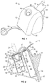
FIG. 1 is a perspective view of an embodiment of a device including a sealing tab; -
FIG. 2 is a cross-sectional diagram of the device ofFIG. 1 ; -
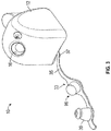
FIG. 3 is a perspective view of a further embodiment of a device having an opening adapter with a plug portion; -
FIG. 4 is a perspective view of the device ofFIG. 3 shown in use; -
FIG. 5 is a perspective view of the device ofFIG. 3 shown during shipping; -
FIG. 6 is a perspective view of a further embodiment of a device having an extra seal; -
FIG. 7 is a perspective view of the device ofFIG. 6 ; -
FIG. 8 is a cross-sectional diagram of the device ofFIG. 6 ; -
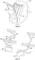
FIG. 9 is a perspective view of another embodiment of a device including a pull out portion with a detail line; -
FIG. 10 is a perspective view of the device ofFIG. 9 with the pull out portion in an open position; and -
FIG. 11 is a cross-sectional diagram of a latch mechanism disposed with another embodiment of the device ofFIG. 9 . - With reference to
FIGS. 1 and 2 , adevice 10 may include a housing orouter shell 12. Thehousing 12 may have anouter surface 14 defining anopening 16 for inserting therein a medical videoscope such as a laparoscope or endoscope or any other surgical tool 31. An interior of thehousing 12 defines acanal 18 having afirst end 20 coupled to theopening 16 and asecond end 22 terminating within thehousing 12 for receiving a distal lens of a medical videoscope. A whitebalancing reference material 24 may be disposed within thehousing 12 adjacent to thesecond end 22 of thecanal 18. - A
defogging material 26 may be stored in thecanal 18 adjacent to thesecond end 22 and used to treat and/or prevent thedistal lens 25 of a medical videoscope 31 from fogging during a medical procedure. Thedevice 10 may include aheating mechanism 28 thermally coupled to thecanal 18 for heating an interior wall of the canal and thesurgical defogging material 26 disposed within the canal to further prevent the distal lens of a medical videoscope from fogging.Heating mechanism 28 may also be thermally coupled to thecanal 18 to heat an interior wall of the canal to prevent a distal lens of a medical videoscope disposed in the canal from fogging when no defogging material may be disposed in the canal. Thedevice 10 may include a self-sealing mechanism 30 disposed at least partly within thecanal 18. Themechanism 30 may allow a medical videoscope to penetrate the seal and make contact with thesurgical defogging material 26 while preventing the surgical defogging material from spilling out of the canal. - The housing or
shell 12 may be made of an insulating foam material such as a medical grade polyurethane foam or another shock absorbing insulating material. Theshell 12 may be designed to protect the lens of a medical videoscope or any other type of instrument from damage prior, during, and after a surgical procedure. An outer cover of theshell 12 may be constructed of high density polyurethane, etha, viscoelastic, latex foams, and the like. The outer cover may also be made of another material such as rubber-like foam, semi-flexible thermoplastic, insulating cardboard, thick insulating fabric, or a plastic frame covered by a silicone or insulating plastic. The outer cover may be selected to have good shock absorbing and insulating properties. - The
device 10 may be shaped as inFIG. 1 or in any other practical shape such as a cube, square, spherical, or tubular shape. Thedevice 10 may have rounded corners or square corners. The exterior dimensions may vary. In some instances, thedevice 10 may be about 4 inches long, 3.5 inches wide, and 4 inches high. In other instances, it may be between as about 15 mm to 6 inches wide, 1 to 6 inches long, and 15 mm to 8 inches high. In other instances the dimensions may vary further and/or thedevice 10 may be sized to accommodate the shape of any medical instrument used. - The
device 10 may include asecuring mechanism 32, as seen inFIG. 2 , coupled to a bottom of thehousing 12. For example, thesecuring mechanism 32 may be a solid flap, which may have approximately same perimeter as the base of thehousing 12. This flap may be attached only either at the front or rear or side bottom part of thedevice 10 so as to create a hinge. The flap may be attached in the middle by two elastic bands. The flap may be constructed of a high-density foam material, cardboard, plastic, or a microfiber material. The external face of the bottom flap may have an adhesive material that may have a protective cover until it may be needed. - When surgery begins and the surgeon brings the
device 10 up to the operative field, the surgeon may secure the device anywhere on top of the drapes by removing a protective cover from an adhesive bottom of the securingmechanism 32 and securing thedevice 10 anywhere on the operative field. Thedevice 10 may also be secured by an assistant to a sterile equipment tray, from which a medical videoscope may then be passed to the surgeon. The securingmechanism 32 may be a flap so that the scope may be inserted vertically. When not in use, theflap 32 allows thedevice 10 to rotate horizontally and rest on the drapes while the scope remains inside the device. Although thedevice 10 may rotate along the hinge of theflap 32, the flap may still maintain thedevice 10 securely attached to the drape with the adhesive coating. - Alternatively, the
device 10 may be constructed without theflap 32 and adhesive may be placed directly on the bottom of the device. Furthermore, thedevice 10 may be secured to any surface through such components such as, but not limited to, adhesives, screws, magnetism, mounts, and clips. Moreover, thedevice 10 may remain unsecured to any surface and be put on and pulled off the scope as needed during the medical procedure. - As shown in
FIGS. 3-5 , thedevice 10 may include anopening adapter 33 to effectively reduce the diameter of theopening 16 for accommodating smaller diameter surgical tools and to close theopening 16 during shipping. Theadapter 33 may include a flexiblelongitudinal stem 35 having abase portion 37 at one end of the stem and a reducedopening portion 39 at another end of the stem. As shown inFIGS. 3-5 , thebase portion 37 may be coupled to a lower portion of thehousing 12. The flexiblelongitudinal stem 35 may be bendable in order to insert the reducedopening portion 39 into theopening 16 of thehousing 12, as shown inFIG. 4 . The openingadapter 33 may be made of a flexible medical grade silicone plastic, but may also be constructed out of other flexible materials. The diameter of the reducedopening portion 39 is shown by way of example to be 5 mm, but need not be 5mm and may vary in other instances. Theadapter 33 also may include aplug portion 96 for use during shipping to ensure that the defogging material does leak out of thedevice 10. Thus, as shown inFIGS. 4 and 5 , theplug portion 96 may close theopening 16 during shipment and the reducedportion 39 may close theopening 16 during the use of thedevice 10. - Referring back to
FIG. 2 , thedevice 10 may include an inner chamber orcenter sheath 34 defining thecanal 18 and accommodated within a cavity of thehousing 12. Thecanal 18 and thecenter sheath 34 are sized and shaped to accommodate a medical videoscope or surgical tool 31 when inserted therein. Thecanal 18 and thesheath 34 extend directly down the center of thedevice 10 from an upper front to a lower back portion. Thesheath 34 may alternatively extend directly down a center or lateral to a center of thedevice 10. The location of thesheath 34 may be in any configuration as long as uniform thermal conductivity may be achieved. The length of thesheath 34 may be about 3 inches long, but may also be other lengths including, but not limited to, between 0.5 to 8 inches. Thesheath 34 may have the shape of a tube. The tubular diameter inside the sheath may be about 5 mm, 10 mm, or any other diameter depending on the size and shape of the medical instrument to be inserted therein. Thesheath 34 may be constructed of stainless steel, aluminum, high-density polyurethane foam, etha foam, viscoelastic foam, latex foam, rubber-like foam, thin plastic, water impermeable fabric, silicon, a rubber-like material, or any materials. Thesheath 34 may all be white or any other color. - As mentioned above, the self-sealing
mechanism 30 may be disposed at least partly within thecanal 18 and thesheath 34 to prevent thesurgical defogging material 26 from spilling out of theopening 16 of thedevice 10. Thecanal 18 or thesheath 34 may accommodate thedefogging material 26 such as an antifog, lens cleaning agent, or surfactant solution, and may lead into or define a reservoir which may be filled with the defogging material. - The self-sealing
mechanism 30 may have the shape of a tube within a tube, shown inFIG. 2 . The self-sealingmechanism 30 may be made of a flexible medical grade silicone plastic. The self-sealingmechanism 30 may be configured to allow a medical videoscope to enter a reservoir at thesecond end 22 of thecanal 18 or inner end of thesheath 34, make contact with thedefogging material 26, and/or prevent a liquid or gel defogging material from spilling out of theopening 16 of thehousing 12 when thedevice 10 is turned upside down and the scope is removed from the device. In other words, the self-sealingmechanism 30 may be configured to function as a type of one-way valve to prevent fluid or gel from leaking. - In one embodiment, the self-sealing
mechanism 30 may include anupper lip 51 seated on thefirst end 20 of thesheath 34. The self-sealingmechanism 30 further may include three flaps orpockets 53 oriented downwardly from theupper lip 51 and spaced from one another circumferentially about a periphery of the self-sealingmechanism 30 such that the pockets are facing an inner surface of thesheath 34. The self-sealingmechanism 30 may have a center tube orduck bill 55 oriented downwardly from theupper lip 51 that defines aslit 57 at a bottom portion thereof for permitting the scope 31 to pass therethrough. Thecenter tube 55 may be spaced radially inwardly of thepockets 53 so as to define a space between the center tube and the pockets. - The self-sealing
mechanism 30 may prevent liquid from spilling out by creating and trapping liquid in the space around afirst end 20 of thecanal 18 or thesheath 34 defining the canal. When thesheath 34 may be turned with the reservoir downward, all the liquid falls into the reservoir. As thesheath 34 and the reservoir are turned upside down, the liquid slides along the side of thesheath 34 and enters the space of the self-sealingmechanism 30 surrounding a distal end of thesheath 34. Thepockets 53 relieve pressure caused by a scope entering the reservoir. With a sealed enclosure provided by thecenter tube 55, as the scope 31 may be inserted through thecenter tube 55, pressure builds as the scope takes up space within the reservoir. The center tube orduck bill 55 may be configured to prevent fluid or air from escaping, and thus the pressure build-up tries to force the scope out of the reservoir. Thepockets 53 may overcome such detrimental pressure build-up upon the scope. As the pressure builds, instead of pushing the scope out of the reservoir, the pockets may deform taking up less space and balancing out the pressure. In other words, thepockets 53 are configured to serve as a pressure compensating system of the self-sealingmechanism 30. - Alternatively, the self-sealing mechanism may resemble a heart valve or be made with a flap and a hinge that only opens in one direction. The self-sealing mechanism may also resemble a valve in a human vein. Moreover, the self-sealing mechanism may be a ball and socket mechanism in which a ball inside the reservoir plugs the hole when the reservoir may be turned upside down but still allows for the scope to enter in the other direction. The self-sealing mechanism may be constructed from a resilient plastic or other rubber-like material. It may also be made from a high-density foam or water impermeable fabric. The self-sealing mechanism may also be made of metal, aluminum, or silicone plastic. The self-sealing mechanism may be any configuration known to a person skilled in the art to prevent leakage and splash back of fluid.
- As shown in
FIG. 2 , the whitebalancing reference material 24 may be disposed adjacent to thesecond end 22 of thecanal 18 such that when a lens of a scope may be placed into the reservoir, the lens approaches within a predetermined distance of thereference material 24. The whitebalancing reference material 24 may be a true white, soft, non-scratch, absorbent material. The material must have a good light diffusing property. The whitebalancing reference material 24 may include a sponge having a white color with a chromaticity of about D-65 or about a D-50 or about D-100. The white color of the whitebalancing reference material 24 may be equal parts of red, blue and green, but may have slight deviations designed to match the camera system specifications of a medical videoscope 31 to be white balanced by the reference material. The whitebalancing reference material 24 may be any desired shape including but not limited to a square, rectangle, ellipse, or circle. The shape of thereference material 24 may be dependent on the shape of the scope to be white balanced. Thereference material 24 may be about ¼ to about 1/16 of an inch thick in some instances but may vary in other instances. Thereference material 24 may be made out of a low density foam or other soft material which may be either hydrophobic or hydrophylic. Thereference material 24 may be made out of white medical grade closed cell foam. - Referring to
FIG. 2 , thereference material 24 may define an indentation or narrowingportion 36 which may be small enough for thedistal lens 25 of a surgical tool, such as a videoscope, 31 to come into contact with the narrowingportion 36 and not further enter the reference material. The narrowingportion 36 may maintain a predetermined space ordistance 41 between the lens and a white surface of a facing base portion 43 of the reference material. Thespace 41 may be of a sufficient distance to allow for proper white balancing of the videoscope 31. - The
defogging material 26, in the form of a gel or liquid, may be made of, but need not be limited to, a combination of water, glycol, and a watersoluble wetting agent, alcohol, and a gelling agent. When in the form of a liquid, thedefogging material 26 may also be made from 1 part poloxamer 188, 99 parts water. A commercially available wound cleaning surfactant solution such as Shurclenz™ may also be diluted with water and used. Other non-ionic surfactants may be used alone or in a mixture. Alcohol may also be used in some instances. If a gelling agent is used, it may be a starch or any super absorbent polymer. Alternatively, any commercially available surgical defogging solution (e.g. F.R.E.D.™ or E.L.V.I.S.™) may be used. - With reference to
FIG. 2 , theheating mechanism 28 may be disposed adjacent to the reservoir of thesecond end 22 of thecanal 18 or thesheath 34 so as to be in thermal communication therewith. Thesheath 34 and the reservoir as part of the sheath may be made of stainless steel or aluminum for efficient heat transfer from theheating mechanism 28 to thedefogging material 26 disposed within the reservoir. Theheating mechanism 28 may include, for example, a heating element (not shown) such as a wound gauge copper wire or nichrome wire. The wire may be connected to apower source 40 such as a battery pack having a housing made of plastic or to another source such as an AC outlet. When activated, electricity flows from thepower source 40 through the heating element so as to heat the reservoir and thedefogging material 26 disposed therein. - A thermistor or switch (not shown) having a thermal component may be placed in the electrical circuit of the
heating mechanism 28 to turn off the flow of electricity when a predetermined temperature may be reached by thedefogging material 26 so as to allow the heating mechanism to maintain a constant temperature of the defogging material above body temperature for an extended period of time while being energized by thepower source 40.Power source 40 may include any type of power source including but not limited tobatteries 44 electrically connected in series. Although the device, for example may have fourAAA batteries 44, different size and different quantities of batteries may be used. A trigger or plunger (not shown) may be coupled to the switch. The plunger may be made of stainless steel, aluminum, plastic, or other generally rigid material. When the plunger is pressed downwardly into the housing, the plunger initially closes the switch to electrically energize theheating mechanism 28 until the thermal component of the switch opens the electrical circuit when the defogging material reaches the predetermined temperature. - Referring to
FIGS. 1 and 2 , in one embodiment, thedevice 10 for accommodating the surgical tool 31 therein may include asealing tab 70 to seal thecanal 18 orsheath 34 and to insulate battery contacts during storage and shipping. Thetab 70 may include a liquidsealing tab portion 71, a batterysealing tab portion 72, and an exposedtab portion 73 such that theliquid sealing portion 71 and thebattery sealing portion 72 are disposed within thedevice 10 and the exposedtab portion 73 may extend outside of thedevice 10. Theliquid sealing portion 71 of thetab 70 may be disposed between an opening 16 of thedevice 10 and a self-sealingmechanism 30 and may provide sealing for thecanal 18 orsheath 34 so that defoggingmaterial 26 does not spill out during storage and shipping of thedevice 10. The batterysealing tab portion 72 of thetab 70 may be disposed between thebatteries 44 andbattery contacts 47. The batterysealing tab portion 72 may provide a protective barrier between thebatteries 44 andbattery contacts 47 before thedevice 10 is used. When thetab 70 is removed from thedevice 10 by being pulled out by the exposedtab portion 72, theliquid sealing portion 71 may be removed from thecanal 18 and thebattery sealing portion 72 may be removed from protecting thebatteries 44 such that thedevice 10 may be activated once thebatteries 44 and thebattery contacts 47 are connected. Although thesealing tab 70 may be shown to have both theliquid sealing portion 71 and abattery sealing portion 72, the sealing tab may include only one of the two portions. - The
device 10 may include analert mechanism 46 to notify a user that at least a portion of the device is being heated by theheating mechanism 28. For example, thealert mechanism 46 may include a light such as anLED 48 or an audible tone generator. Alternatively, a thermometer or heat sensitive paint may be used as an indicator of activation of theheating mechanism 28. - Referring to
FIGS. 6, 7 and8 , in an alternative embodiment, adevice 110 may include anextra seal 190 with a warm upindicator 192. Theextra seal 190 may be disposed about theopening 116 of thedevice 110 and may be visible from the outside of the device. Theseal 190 may change color when the device heats up to indicate that the device may be ready for use. Theextra seal 190 may be fabricated from thermo-chromic elastomeric material or the like and may include colorant therein to indicate color change when the device heats up to show to the user that the device may be ready for use. Thus, theseal 190 may serve a dual purpose of providing additional sealing and of providing an indication that the device may be ready for use. - The
device 10 may also have amicrofiber fabric 50 on all or part of theouter surface 14 of thehousing 12 so that a scope lens may be wiped thereon and cleaned during a surgical procedure. Thehousing 12 may define aledge 61 and adepressed surface portion 63 which may be covered by themicrofiber 50 and against which a scope may be wiped clean. Themicrofiber 50 may be either permanently or removably attachable to thedevice 10. Themicrofiber 50 may be, but may be not limited to, any combination of polyester and nylon. - As mentioned above, the
sheath 34 and the reservoir may be constructed of stainless steel or aluminum, but any metal with good heat transfer properties may be used. - Because a medical videoscope may be submerged in the defogging material, the
device 10 may reduce the risk of a fire hazard as hot light from the scope may be not allowed to concentrate on a drape or on the patient when the scope is submerged in the defogging material. - The
device 10 may also be packaged in combination with other medical videoscopic care products such as microfiber surgical sponges, trocar wipes, and a microfiber patient cleaning set. A kit containing this white balancing and defogging device in combination with other medical videoscopic care products may be called a "laparoscopic care kit" or a "laparoscopic care pack." - The
device 10 may be oriented to maintain a videoscope such as, for example, laparoscope 31 or any other surgical tool, inserted therein in an upright position. Alternatively, thedevice 10 may be oriented to maintain the laparoscope 31 inserted therein in a resting position. The securingmechanism 32 of thedevice 10 may serve as a hinge. The adhesive in the bottom of thedevice 10 may allow the device to be secured to drapes or to a table and still allow for the scope 31 to rest freely. This may enable the scope 31 to remain inside thedevice 10 so as to prevent a fire hazard whenever the scope is not in use. - Referring to
FIGS. 9 and10 , in another embodiment, adevice 210 may include adetail line 280 formed withinhousing 212 of thedevice 210 to define a pull outportion 282 therein. Thedetail line 280 is shown as having a U-shaped contour, but other shapes may be formed. Thedetail line 280 may be formed to allow easy tear path for removal ofbatteries 244 and destruction of thedevice 210. The pull out portion may be easily moved into an open position, as shown inFIG. 10 , to expose thebatteries 244. Once thebatteries 244 are exposed, the batteries may be removed. Thus, after thedevice 210 has been used, the pull outportion 282 may be pulled along thedetail line 280 from thedevice 210 to separate from thehousing 212 into an open position and to exposebatteries 244 for removal to prevent unsafe reuse of thedevice 210. - Referring to
FIG. 11 , in a further embodiment, alatch mechanism 284 may be included to ensure that the device may be not reused after the initial intended use. Thelatch mechanism 284 may include adetent 286 disposed on abattery contact 247. As thebatteries 244 are dislodged from the original position, the spring-loadedcontact 247 may expand through an opening 288 formed in awall 289 such that the detent passes through the opening 288 and engages thewall 289. Once thebatteries 244 have been moved from the original position, thelatch mechanism 284 may activate to preclude re-insertion of the batteries and reuse of the device. - While the above invention may have been described with reference to certain preferred embodiments, the scope of the present invention may be not limited to these embodiments. For example, although the white balancing reference material and defogging material are shown and described as being part of a single device, it should be understood that the white balancing reference material and defogging material may be disposed in separate devices working either simultaneously or non-simultaneously with one another without departing from the scope of the present invention. One skilled in the art may find other variations of these preferred embodiments which, nevertheless, fall within the scope of the present invention.
Claims (14)
- A device (10) for accommodating a surgical tool (31), the device comprising:a housing (12) having an outer surface (14) defining an opening (16), an interior of the housing defining a canal (18) for receiving a surgical tool, the canal having a first end (20) coupled to the opening and a second end (22) terminating within the housing;at least one battery (44) for powering the device, the battery coming into contact with a battery contact (47); anda sealing tab (70) having a battery sealing portion (72) for insulating the battery contact prior to the use of the device wherein the sealing tab (70) further comprises a liquid sealing portion (71) for providing sealing for liquid disposed within the canal (18), herein said liquid sealing portion (71) of the sealing tab (70) is disposed between the opening (16) of the device (10) and a self-sealing mechanism (30) and provides sealing for the canal (18) so that defogging material (26) does not spill out.
- The device (10) according to claim 1 wherein the battery sealing portion (72) of the sealing tab (70) may be disposed between the at least one battery (44) and the battery contact (47).
- The device (10) according to any preceding claim wherein the sealing tab (70) further comprises an exposed portion (73) disposed outside of the housing (12) for easy removal of the sealing tab from the device.
- A device (210) for accommodating a surgical tool (31) according to any preceding claim further comprising a pull out portion (282) formed within the housing to allow access to the interior of the device.
- The device (210) according to claim 4 wherein the pull out portion (282) may be defined by a detail line (28) formed within the housing (212); preferably wherein the pull out portion may be separated from the housing along the detail line.
- The device (210) according to claim 4 wherein once the pull out portion (282) may be separated from the housing (212), batteries (244) disposed within the housing may be removed from the device.
- The device (210) according to claim 4 further comprising a latch mechanism (284) to ensure that batteries (244) cannot be reinserted; preferably wherein the latch mechanism may include a detent (286) disposed on a battery contact and activated once the batteries are dislodged from the original position.
- A device (110) for accommodating a surgical tool (31) according to any preceding claim, said device further comprising:
an extra seal (190) disposed about the opening to provide extra sealing and to provide an indication when the device may be ready for use. - The device (110) according to claim 8 wherein the extra seal (190) may be fabricated from a material that changes color upon heating.
- The device (110) according to claim 8 or claim 9 wherein the extra seal (190) may be fabricated from a thermo-chromic elastomeric material.
- A device (10) for accommodating a surgical tool (31) therein according to any preceding claim, the device further comprising an opening adapter to close the opening during shipping.
- The device (10) according to claim 11 wherein the opening adapter (33) comprises a plug portion (96) for use during shipping to ensure that defogging material does leak out of the device.
- The device (10) according to claim 11 or claim 12 wherein the opening adapter (33) also effectively reduces the diameter of the opening for accommodating smaller diameter surgical tools preferably wherein the opening adapter further comprises a reduced opening portion (39) to reduce the diameter of the opening for accommodating smaller diameter surgical tools.
- The device (10) according to any of claims 11 to 13 wherein the opening adapter (33) may be fabricated from a flexible material.
Applications Claiming Priority (2)
| Application Number | Priority Date | Filing Date | Title |
|---|---|---|---|
| US201562103871P | 2015-01-15 | 2015-01-15 | |
| PCT/US2016/013349 WO2016115310A2 (en) | 2015-01-15 | 2016-01-14 | Device for accommodating surgical tool prior to and during medical procedures |
Publications (3)
| Publication Number | Publication Date |
|---|---|
| EP3244823A2 EP3244823A2 (en) | 2017-11-22 |
| EP3244823A4 EP3244823A4 (en) | 2018-08-15 |
| EP3244823B1 true EP3244823B1 (en) | 2021-03-03 |
Family
ID=56406564
Family Applications (1)
| Application Number | Title | Priority Date | Filing Date |
|---|---|---|---|
| EP16737858.7A Active EP3244823B1 (en) | 2015-01-15 | 2016-01-14 | Device for accommodating surgical tool prior to and during medical procedures |
Country Status (8)
| Country | Link |
|---|---|
| US (1) | US11452439B2 (en) |
| EP (1) | EP3244823B1 (en) |
| JP (1) | JP6633639B2 (en) |
| CN (1) | CN107106000A (en) |
| AU (1) | AU2016206743B2 (en) |
| CA (1) | CA2972482A1 (en) |
| ES (1) | ES2862151T3 (en) |
| WO (1) | WO2016115310A2 (en) |
Families Citing this family (9)
| Publication number | Priority date | Publication date | Assignee | Title |
|---|---|---|---|---|
| WO2017079318A1 (en) * | 2015-11-02 | 2017-05-11 | Buffalo Filter Llc | Fluid filtration, cleaning, and defogging device |
| US10987103B2 (en) | 2017-06-27 | 2021-04-27 | Ethicon Llc | Powered surgical instrument with latching feature preventing removal of battery pack |
| US10278572B1 (en) * | 2017-10-19 | 2019-05-07 | Obp Medical Corporation | Speculum |
| US20190159665A1 (en) * | 2017-11-28 | 2019-05-30 | Covidien Lp | Devices for cleaning medical videoscopes |
| WO2019236538A1 (en) * | 2018-06-06 | 2019-12-12 | Lenox Dwight H Ii | Method and apparatus for warming a tip-portion of an optical scope prior to in-vivo use for imaging |
| EP4178412A4 (en) * | 2020-07-12 | 2023-12-27 | 270 Surgical Ltd. | White balance apparatus |
| CN112826436A (en) * | 2021-01-21 | 2021-05-25 | 青岛大学附属医院 | Disposable lens warmer |
| WO2023073657A1 (en) * | 2021-11-01 | 2023-05-04 | Covidien Lp | Pull tab including an integrated seal for use with an endoscope cleaning device |
| WO2023111709A1 (en) * | 2021-12-15 | 2023-06-22 | Covidien Lp | Endoscope cleaning devices |
Family Cites Families (29)
| Publication number | Priority date | Publication date | Assignee | Title |
|---|---|---|---|---|
| US7033339B1 (en) * | 1998-05-29 | 2006-04-25 | Becton Dickinson And Company (Part Interest) | Self sealing luer receiving stopcock |
| US5549543A (en) * | 1995-06-01 | 1996-08-27 | Kim; Il G. | Laparoscopic defogging apparatus |
| AU6273899A (en) * | 1998-10-01 | 2000-04-17 | Minntech Corporation | Reverse flow cleaning and sterilizing device and method |
| AUPQ036599A0 (en) * | 1999-05-14 | 1999-06-10 | Fairmont Medical Products Pty Ltd | Sterilisation method and container therefor |
| US6377848B1 (en) * | 1999-08-25 | 2002-04-23 | Vyteris, Inc. | Devices activating an iontophoretic delivery device |
| WO2001060239A1 (en) * | 2000-02-18 | 2001-08-23 | University Of Massachussets | Devices and methods for warming and cleaning lenses of optical surgical instruments |
| JP2001255631A (en) * | 2000-03-08 | 2001-09-21 | Konica Corp | Lens-fitted photographic film unit and its battery pulling-out method |
| DE60214345T2 (en) * | 2001-01-12 | 2007-04-12 | Noshmell PTY Ltd., Bondi Junction | DISPOSABLE BEVERAGE CONTAINER WITH A LID |
| DE20114741U1 (en) * | 2001-09-07 | 2003-01-30 | Ackermann Bruno | Container with twist lock |
| US6634516B2 (en) * | 2002-01-07 | 2003-10-21 | Fabricas Monterrey, S.A. De C.V. | Color changing closure for bottling applications |
| US6929136B2 (en) * | 2002-01-08 | 2005-08-16 | Fabricas Monterrey, S.A. De C.V. | Thermochromic cap |
| JP4422501B2 (en) * | 2004-01-21 | 2010-02-24 | オリンパス株式会社 | Endoscope and endoscope system |
| US7311660B2 (en) * | 2004-04-16 | 2007-12-25 | Ricardo Alexander Gomez | Method and apparatus for heating and applying warm antifog solution to endoscopes as well as a distal lens protector |
| US7540852B2 (en) * | 2004-08-26 | 2009-06-02 | Flowcardia, Inc. | Ultrasound catheter devices and methods |
| KR101250611B1 (en) * | 2006-01-30 | 2013-04-09 | 뉴 웨이브 서지컬 코포레이션. | Device for white balancing and applying an anti―fog agent to medical videoscopes prior to medical procedures |
| US8690831B2 (en) * | 2008-04-25 | 2014-04-08 | Ethicon Endo-Surgery, Inc. | Gas jet fluid removal in a trocar |
| US8137303B2 (en) * | 2006-05-08 | 2012-03-20 | Becton, Dickinson And Company | Vascular access device cleaning status indication |
| US20080107564A1 (en) * | 2006-07-20 | 2008-05-08 | Shmuel Sternberg | Medical fluid access site with antiseptic indicator |
| US20080021392A1 (en) * | 2006-07-20 | 2008-01-24 | Lurvey Kent L | Medical fluid access site with antiseptic indicator |
| US8491471B2 (en) * | 2006-08-31 | 2013-07-23 | Dignity Health | Inflatable surgical retractor |
| US9326667B2 (en) * | 2007-10-26 | 2016-05-03 | C Change Surgical Llc | Anti-fogging and cleaning apparatus for medical scopes |
| NZ618255A (en) * | 2009-06-02 | 2015-05-29 | Resmed Ltd | Unobtrusive nasal mask |
| US20110108554A1 (en) * | 2009-11-12 | 2011-05-12 | Ladison Timothy J | Transparent sterilization, storage, display and transportaion system |
| WO2012068240A2 (en) * | 2010-11-16 | 2012-05-24 | Symmetry Medical Manufacturing, Inc. | Apparatus and method for indicating biological content within a container |
| WO2012094426A2 (en) * | 2011-01-04 | 2012-07-12 | Schwartz Alan N | Gel-based seals and fixation devices and associated systems and methods |
| US8673242B2 (en) * | 2011-09-06 | 2014-03-18 | National Scientific Company | Over-torque resistant vial |
| JP2013165805A (en) * | 2012-02-15 | 2013-08-29 | Johnson & Johnson Kk | Container opening mechanism and endoscope washing device |
| JP2015519182A (en) * | 2012-06-13 | 2015-07-09 | ドクター ピー インスティチュート エルエルシー | Device with penetrable diaphragm and closure, and needle |
| US20140001142A1 (en) * | 2012-06-27 | 2014-01-02 | Chris Wu | Nursing bottle with temperature indicator |
-
2016
- 2016-01-14 JP JP2017537269A patent/JP6633639B2/en not_active Expired - Fee Related
- 2016-01-14 CN CN201680005954.9A patent/CN107106000A/en active Pending
- 2016-01-14 WO PCT/US2016/013349 patent/WO2016115310A2/en active Application Filing
- 2016-01-14 AU AU2016206743A patent/AU2016206743B2/en not_active Ceased
- 2016-01-14 CA CA2972482A patent/CA2972482A1/en not_active Abandoned
- 2016-01-14 EP EP16737858.7A patent/EP3244823B1/en active Active
- 2016-01-14 ES ES16737858T patent/ES2862151T3/en active Active
- 2016-01-21 US US15/544,047 patent/US11452439B2/en active Active
Non-Patent Citations (1)
| Title |
|---|
| None * |
Also Published As
| Publication number | Publication date |
|---|---|
| CA2972482A1 (en) | 2016-07-21 |
| ES2862151T3 (en) | 2021-10-07 |
| US11452439B2 (en) | 2022-09-27 |
| EP3244823A4 (en) | 2018-08-15 |
| WO2016115310A2 (en) | 2016-07-21 |
| US20180263481A1 (en) | 2018-09-20 |
| CN107106000A (en) | 2017-08-29 |
| JP2018505722A (en) | 2018-03-01 |
| JP6633639B2 (en) | 2020-01-22 |
| EP3244823A2 (en) | 2017-11-22 |
| WO2016115310A3 (en) | 2016-09-09 |
| AU2016206743A1 (en) | 2017-07-13 |
| AU2016206743B2 (en) | 2020-02-27 |
Similar Documents
| Publication | Publication Date | Title |
|---|---|---|
| EP3244823B1 (en) | Device for accommodating surgical tool prior to and during medical procedures | |
| ES2614487T3 (en) | Device for balancing the targets and applying an anti-fogging agent to medical videoscopes before medical procedures | |
| US10881284B2 (en) | Scope cleaning device configured to be removeably connected to a surgical tool | |
| US11284790B2 (en) | Laparoscopic visualization system | |
| JP5628742B2 (en) | Scope heating device | |
| US9326667B2 (en) | Anti-fogging and cleaning apparatus for medical scopes | |
| US7803109B2 (en) | Method and apparatus for protecting the distal lens of endoscopes | |
| EP3488761A1 (en) | Devices and methods for cleaning medical videoscopes | |
| US20160331220A1 (en) | Medical device cleaning system |
Legal Events
| Date | Code | Title | Description |
|---|---|---|---|
| STAA | Information on the status of an ep patent application or granted ep patent |
Free format text: STATUS: THE INTERNATIONAL PUBLICATION HAS BEEN MADE |
|
| PUAI | Public reference made under article 153(3) epc to a published international application that has entered the european phase |
Free format text: ORIGINAL CODE: 0009012 |
|
| STAA | Information on the status of an ep patent application or granted ep patent |
Free format text: STATUS: REQUEST FOR EXAMINATION WAS MADE |
|
| 17P | Request for examination filed |
Effective date: 20170814 |
|
| AK | Designated contracting states |
Kind code of ref document: A2 Designated state(s): AL AT BE BG CH CY CZ DE DK EE ES FI FR GB GR HR HU IE IS IT LI LT LU LV MC MK MT NL NO PL PT RO RS SE SI SK SM TR |
|
| AX | Request for extension of the european patent |
Extension state: BA ME |
|
| DAV | Request for validation of the european patent (deleted) | ||
| DAX | Request for extension of the european patent (deleted) | ||
| A4 | Supplementary search report drawn up and despatched |
Effective date: 20180717 |
|
| RIC1 | Information provided on ipc code assigned before grant |
Ipc: A61B 1/00 20060101ALI20180711BHEP Ipc: A61B 90/00 20160101ALI20180711BHEP Ipc: A61B 1/12 20060101ALI20180711BHEP Ipc: A61B 1/313 20060101ALI20180711BHEP Ipc: A61B 1/04 20060101ALI20180711BHEP Ipc: H04N 9/73 20060101ALI20180711BHEP Ipc: A61B 90/70 20160101AFI20180711BHEP |
|
| STAA | Information on the status of an ep patent application or granted ep patent |
Free format text: STATUS: EXAMINATION IS IN PROGRESS |
|
| 17Q | First examination report despatched |
Effective date: 20200430 |
|
| GRAP | Despatch of communication of intention to grant a patent |
Free format text: ORIGINAL CODE: EPIDOSNIGR1 |
|
| STAA | Information on the status of an ep patent application or granted ep patent |
Free format text: STATUS: GRANT OF PATENT IS INTENDED |
|
| INTG | Intention to grant announced |
Effective date: 20200917 |
|
| GRAS | Grant fee paid |
Free format text: ORIGINAL CODE: EPIDOSNIGR3 |
|
| STAA | Information on the status of an ep patent application or granted ep patent |
Free format text: STATUS: GRANT OF PATENT IS INTENDED |
|
| GRAA | (expected) grant |
Free format text: ORIGINAL CODE: 0009210 |
|
| STAA | Information on the status of an ep patent application or granted ep patent |
Free format text: STATUS: THE PATENT HAS BEEN GRANTED |
|
| AK | Designated contracting states |
Kind code of ref document: B1 Designated state(s): AL AT BE BG CH CY CZ DE DK EE ES FI FR GB GR HR HU IE IS IT LI LT LU LV MC MK MT NL NO PL PT RO RS SE SI SK SM TR |
|
| REG | Reference to a national code |
Ref country code: GB Ref legal event code: FG4D |
|
| REG | Reference to a national code |
Ref country code: AT Ref legal event code: REF Ref document number: 1366371 Country of ref document: AT Kind code of ref document: T Effective date: 20210315 Ref country code: CH Ref legal event code: EP |
|
| REG | Reference to a national code |
Ref country code: DE Ref legal event code: R096 Ref document number: 602016053559 Country of ref document: DE |
|
| REG | Reference to a national code |
Ref country code: CH Ref legal event code: NV Representative=s name: NOVAGRAAF INTERNATIONAL SA, CH Ref country code: IE Ref legal event code: FG4D |
|
| REG | Reference to a national code |
Ref country code: LT Ref legal event code: MG9D |
|
| PG25 | Lapsed in a contracting state [announced via postgrant information from national office to epo] |
Ref country code: HR Free format text: LAPSE BECAUSE OF FAILURE TO SUBMIT A TRANSLATION OF THE DESCRIPTION OR TO PAY THE FEE WITHIN THE PRESCRIBED TIME-LIMIT Effective date: 20210303 Ref country code: FI Free format text: LAPSE BECAUSE OF FAILURE TO SUBMIT A TRANSLATION OF THE DESCRIPTION OR TO PAY THE FEE WITHIN THE PRESCRIBED TIME-LIMIT Effective date: 20210303 Ref country code: GR Free format text: LAPSE BECAUSE OF FAILURE TO SUBMIT A TRANSLATION OF THE DESCRIPTION OR TO PAY THE FEE WITHIN THE PRESCRIBED TIME-LIMIT Effective date: 20210604 Ref country code: NO Free format text: LAPSE BECAUSE OF FAILURE TO SUBMIT A TRANSLATION OF THE DESCRIPTION OR TO PAY THE FEE WITHIN THE PRESCRIBED TIME-LIMIT Effective date: 20210603 Ref country code: BG Free format text: LAPSE BECAUSE OF FAILURE TO SUBMIT A TRANSLATION OF THE DESCRIPTION OR TO PAY THE FEE WITHIN THE PRESCRIBED TIME-LIMIT Effective date: 20210603 Ref country code: LT Free format text: LAPSE BECAUSE OF FAILURE TO SUBMIT A TRANSLATION OF THE DESCRIPTION OR TO PAY THE FEE WITHIN THE PRESCRIBED TIME-LIMIT Effective date: 20210303 |
|
| REG | Reference to a national code |
Ref country code: NL Ref legal event code: MP Effective date: 20210303 |
|
| REG | Reference to a national code |
Ref country code: AT Ref legal event code: MK05 Ref document number: 1366371 Country of ref document: AT Kind code of ref document: T Effective date: 20210303 |
|
| PG25 | Lapsed in a contracting state [announced via postgrant information from national office to epo] |
Ref country code: SE Free format text: LAPSE BECAUSE OF FAILURE TO SUBMIT A TRANSLATION OF THE DESCRIPTION OR TO PAY THE FEE WITHIN THE PRESCRIBED TIME-LIMIT Effective date: 20210303 Ref country code: PL Free format text: LAPSE BECAUSE OF FAILURE TO SUBMIT A TRANSLATION OF THE DESCRIPTION OR TO PAY THE FEE WITHIN THE PRESCRIBED TIME-LIMIT Effective date: 20210303 Ref country code: RS Free format text: LAPSE BECAUSE OF FAILURE TO SUBMIT A TRANSLATION OF THE DESCRIPTION OR TO PAY THE FEE WITHIN THE PRESCRIBED TIME-LIMIT Effective date: 20210303 Ref country code: LV Free format text: LAPSE BECAUSE OF FAILURE TO SUBMIT A TRANSLATION OF THE DESCRIPTION OR TO PAY THE FEE WITHIN THE PRESCRIBED TIME-LIMIT Effective date: 20210303 |
|
| PG25 | Lapsed in a contracting state [announced via postgrant information from national office to epo] |
Ref country code: NL Free format text: LAPSE BECAUSE OF FAILURE TO SUBMIT A TRANSLATION OF THE DESCRIPTION OR TO PAY THE FEE WITHIN THE PRESCRIBED TIME-LIMIT Effective date: 20210303 |
|
| REG | Reference to a national code |
Ref country code: ES Ref legal event code: FG2A Ref document number: 2862151 Country of ref document: ES Kind code of ref document: T3 Effective date: 20211007 |
|
| PG25 | Lapsed in a contracting state [announced via postgrant information from national office to epo] |
Ref country code: EE Free format text: LAPSE BECAUSE OF FAILURE TO SUBMIT A TRANSLATION OF THE DESCRIPTION OR TO PAY THE FEE WITHIN THE PRESCRIBED TIME-LIMIT Effective date: 20210303 Ref country code: CZ Free format text: LAPSE BECAUSE OF FAILURE TO SUBMIT A TRANSLATION OF THE DESCRIPTION OR TO PAY THE FEE WITHIN THE PRESCRIBED TIME-LIMIT Effective date: 20210303 Ref country code: SM Free format text: LAPSE BECAUSE OF FAILURE TO SUBMIT A TRANSLATION OF THE DESCRIPTION OR TO PAY THE FEE WITHIN THE PRESCRIBED TIME-LIMIT Effective date: 20210303 Ref country code: AT Free format text: LAPSE BECAUSE OF FAILURE TO SUBMIT A TRANSLATION OF THE DESCRIPTION OR TO PAY THE FEE WITHIN THE PRESCRIBED TIME-LIMIT Effective date: 20210303 |
|
| PG25 | Lapsed in a contracting state [announced via postgrant information from national office to epo] |
Ref country code: SK Free format text: LAPSE BECAUSE OF FAILURE TO SUBMIT A TRANSLATION OF THE DESCRIPTION OR TO PAY THE FEE WITHIN THE PRESCRIBED TIME-LIMIT Effective date: 20210303 Ref country code: RO Free format text: LAPSE BECAUSE OF FAILURE TO SUBMIT A TRANSLATION OF THE DESCRIPTION OR TO PAY THE FEE WITHIN THE PRESCRIBED TIME-LIMIT Effective date: 20210303 Ref country code: PT Free format text: LAPSE BECAUSE OF FAILURE TO SUBMIT A TRANSLATION OF THE DESCRIPTION OR TO PAY THE FEE WITHIN THE PRESCRIBED TIME-LIMIT Effective date: 20210705 Ref country code: IS Free format text: LAPSE BECAUSE OF FAILURE TO SUBMIT A TRANSLATION OF THE DESCRIPTION OR TO PAY THE FEE WITHIN THE PRESCRIBED TIME-LIMIT Effective date: 20210703 |
|
| REG | Reference to a national code |
Ref country code: DE Ref legal event code: R097 Ref document number: 602016053559 Country of ref document: DE |
|
| PLBE | No opposition filed within time limit |
Free format text: ORIGINAL CODE: 0009261 |
|
| STAA | Information on the status of an ep patent application or granted ep patent |
Free format text: STATUS: NO OPPOSITION FILED WITHIN TIME LIMIT |
|
| PG25 | Lapsed in a contracting state [announced via postgrant information from national office to epo] |
Ref country code: AL Free format text: LAPSE BECAUSE OF FAILURE TO SUBMIT A TRANSLATION OF THE DESCRIPTION OR TO PAY THE FEE WITHIN THE PRESCRIBED TIME-LIMIT Effective date: 20210303 Ref country code: DK Free format text: LAPSE BECAUSE OF FAILURE TO SUBMIT A TRANSLATION OF THE DESCRIPTION OR TO PAY THE FEE WITHIN THE PRESCRIBED TIME-LIMIT Effective date: 20210303 |
|
| 26N | No opposition filed |
Effective date: 20211206 |
|
| PG25 | Lapsed in a contracting state [announced via postgrant information from national office to epo] |
Ref country code: SI Free format text: LAPSE BECAUSE OF FAILURE TO SUBMIT A TRANSLATION OF THE DESCRIPTION OR TO PAY THE FEE WITHIN THE PRESCRIBED TIME-LIMIT Effective date: 20210303 |
|
| PG25 | Lapsed in a contracting state [announced via postgrant information from national office to epo] |
Ref country code: IT Free format text: LAPSE BECAUSE OF FAILURE TO SUBMIT A TRANSLATION OF THE DESCRIPTION OR TO PAY THE FEE WITHIN THE PRESCRIBED TIME-LIMIT Effective date: 20210303 |
|
| PG25 | Lapsed in a contracting state [announced via postgrant information from national office to epo] |
Ref country code: IS Free format text: LAPSE BECAUSE OF FAILURE TO SUBMIT A TRANSLATION OF THE DESCRIPTION OR TO PAY THE FEE WITHIN THE PRESCRIBED TIME-LIMIT Effective date: 20210703 |
|
| PGFP | Annual fee paid to national office [announced via postgrant information from national office to epo] |
Ref country code: ES Payment date: 20220201 Year of fee payment: 7 |
|
| PG25 | Lapsed in a contracting state [announced via postgrant information from national office to epo] |
Ref country code: MC Free format text: LAPSE BECAUSE OF FAILURE TO SUBMIT A TRANSLATION OF THE DESCRIPTION OR TO PAY THE FEE WITHIN THE PRESCRIBED TIME-LIMIT Effective date: 20210303 |
|
| REG | Reference to a national code |
Ref country code: CH Ref legal event code: PL |
|
| GBPC | Gb: european patent ceased through non-payment of renewal fee |
Effective date: 20220114 |
|
| REG | Reference to a national code |
Ref country code: BE Ref legal event code: MM Effective date: 20220131 |
|
| PG25 | Lapsed in a contracting state [announced via postgrant information from national office to epo] |
Ref country code: LU Free format text: LAPSE BECAUSE OF NON-PAYMENT OF DUE FEES Effective date: 20220114 Ref country code: GB Free format text: LAPSE BECAUSE OF NON-PAYMENT OF DUE FEES Effective date: 20220114 |
|
| PG25 | Lapsed in a contracting state [announced via postgrant information from national office to epo] |
Ref country code: BE Free format text: LAPSE BECAUSE OF NON-PAYMENT OF DUE FEES Effective date: 20220131 |
|
| PG25 | Lapsed in a contracting state [announced via postgrant information from national office to epo] |
Ref country code: LI Free format text: LAPSE BECAUSE OF NON-PAYMENT OF DUE FEES Effective date: 20220131 Ref country code: CH Free format text: LAPSE BECAUSE OF NON-PAYMENT OF DUE FEES Effective date: 20220131 |
|
| PG25 | Lapsed in a contracting state [announced via postgrant information from national office to epo] |
Ref country code: IE Free format text: LAPSE BECAUSE OF NON-PAYMENT OF DUE FEES Effective date: 20220114 |
|
| PGFP | Annual fee paid to national office [announced via postgrant information from national office to epo] |
Ref country code: DE Payment date: 20221220 Year of fee payment: 8 |
|
| PGFP | Annual fee paid to national office [announced via postgrant information from national office to epo] |
Ref country code: FR Payment date: 20231219 Year of fee payment: 9 |
|
| REG | Reference to a national code |
Ref country code: ES Ref legal event code: FD2A Effective date: 20240327 |
|
| PG25 | Lapsed in a contracting state [announced via postgrant information from national office to epo] |
Ref country code: HU Free format text: LAPSE BECAUSE OF FAILURE TO SUBMIT A TRANSLATION OF THE DESCRIPTION OR TO PAY THE FEE WITHIN THE PRESCRIBED TIME-LIMIT; INVALID AB INITIO Effective date: 20160114 |
|
| PG25 | Lapsed in a contracting state [announced via postgrant information from national office to epo] |
Ref country code: ES Free format text: LAPSE BECAUSE OF NON-PAYMENT OF DUE FEES Effective date: 20230115 |