EP3244766B1 - Sole structure with bottom-loaded compression - Google Patents
Sole structure with bottom-loaded compression Download PDFInfo
- Publication number
- EP3244766B1 EP3244766B1 EP16737734.0A EP16737734A EP3244766B1 EP 3244766 B1 EP3244766 B1 EP 3244766B1 EP 16737734 A EP16737734 A EP 16737734A EP 3244766 B1 EP3244766 B1 EP 3244766B1
- Authority
- EP
- European Patent Office
- Prior art keywords
- midsole
- outsole
- sole structure
- traction
- footwear
- Prior art date
- Legal status (The legal status is an assumption and is not a legal conclusion. Google has not performed a legal analysis and makes no representation as to the accuracy of the status listed.)
- Active
Links
- 230000006835 compression Effects 0.000 title claims description 62
- 238000007906 compression Methods 0.000 title claims description 62
- 239000000463 material Substances 0.000 claims description 55
- 210000000548 hind-foot Anatomy 0.000 claims description 13
- 210000004744 fore-foot Anatomy 0.000 claims description 12
- 239000005038 ethylene vinyl acetate Substances 0.000 claims description 8
- 230000002093 peripheral effect Effects 0.000 claims description 8
- 210000002683 foot Anatomy 0.000 description 14
- 239000006260 foam Substances 0.000 description 8
- 229920002725 thermoplastic elastomer Polymers 0.000 description 8
- 210000000452 mid-foot Anatomy 0.000 description 7
- 229920001200 poly(ethylene-vinyl acetate) Polymers 0.000 description 7
- 229920001971 elastomer Polymers 0.000 description 6
- 239000006261 foam material Substances 0.000 description 6
- 238000012876 topography Methods 0.000 description 6
- DQXBYHZEEUGOBF-UHFFFAOYSA-N but-3-enoic acid;ethene Chemical compound C=C.OC(=O)CC=C DQXBYHZEEUGOBF-UHFFFAOYSA-N 0.000 description 4
- 230000000694 effects Effects 0.000 description 4
- 238000003780 insertion Methods 0.000 description 4
- 230000037431 insertion Effects 0.000 description 4
- 239000012528 membrane Substances 0.000 description 4
- 239000005060 rubber Substances 0.000 description 4
- 210000003423 ankle Anatomy 0.000 description 3
- 238000012669 compression test Methods 0.000 description 3
- 230000005021 gait Effects 0.000 description 3
- 238000002955 isolation Methods 0.000 description 3
- 238000000034 method Methods 0.000 description 3
- 230000004044 response Effects 0.000 description 3
- 210000003371 toe Anatomy 0.000 description 3
- 230000009471 action Effects 0.000 description 2
- 238000004026 adhesive bonding Methods 0.000 description 2
- 239000000806 elastomer Substances 0.000 description 2
- 238000007373 indentation Methods 0.000 description 2
- 238000004519 manufacturing process Methods 0.000 description 2
- 238000005259 measurement Methods 0.000 description 2
- 238000012986 modification Methods 0.000 description 2
- 230000004048 modification Effects 0.000 description 2
- 229920000098 polyolefin Polymers 0.000 description 2
- 238000011084 recovery Methods 0.000 description 2
- 230000035939 shock Effects 0.000 description 2
- JOYRKODLDBILNP-UHFFFAOYSA-N Ethyl urethane Chemical compound CCOC(N)=O JOYRKODLDBILNP-UHFFFAOYSA-N 0.000 description 1
- 244000043261 Hevea brasiliensis Species 0.000 description 1
- 229920005830 Polyurethane Foam Polymers 0.000 description 1
- 238000001467 acupuncture Methods 0.000 description 1
- 150000001336 alkenes Chemical class 0.000 description 1
- 230000009286 beneficial effect Effects 0.000 description 1
- 229920001400 block copolymer Polymers 0.000 description 1
- 230000003139 buffering effect Effects 0.000 description 1
- 230000001419 dependent effect Effects 0.000 description 1
- 210000000454 fifth toe Anatomy 0.000 description 1
- 210000001255 hallux Anatomy 0.000 description 1
- 230000001788 irregular Effects 0.000 description 1
- 239000010985 leather Substances 0.000 description 1
- 239000002649 leather substitute Substances 0.000 description 1
- 239000000203 mixture Substances 0.000 description 1
- 239000003607 modifier Substances 0.000 description 1
- 238000000465 moulding Methods 0.000 description 1
- 229920003052 natural elastomer Polymers 0.000 description 1
- 229920001194 natural rubber Polymers 0.000 description 1
- JRZJOMJEPLMPRA-UHFFFAOYSA-N olefin Natural products CCCCCCCC=C JRZJOMJEPLMPRA-UHFFFAOYSA-N 0.000 description 1
- 230000037081 physical activity Effects 0.000 description 1
- 229920000642 polymer Polymers 0.000 description 1
- 230000008569 process Effects 0.000 description 1
- 239000011435 rock Substances 0.000 description 1
- -1 siloxanes Chemical class 0.000 description 1
- 238000004513 sizing Methods 0.000 description 1
- 230000000638 stimulation Effects 0.000 description 1
- 239000000725 suspension Substances 0.000 description 1
- 229920003051 synthetic elastomer Polymers 0.000 description 1
- 239000005061 synthetic rubber Substances 0.000 description 1
- 239000004753 textile Substances 0.000 description 1
- 229920001169 thermoplastic Polymers 0.000 description 1
- 239000004416 thermosoftening plastic Substances 0.000 description 1
- 229920000428 triblock copolymer Polymers 0.000 description 1
- 230000000007 visual effect Effects 0.000 description 1
- 239000013585 weight reducing agent Substances 0.000 description 1
Images


Classifications
-
- A—HUMAN NECESSITIES
- A43—FOOTWEAR
- A43B—CHARACTERISTIC FEATURES OF FOOTWEAR; PARTS OF FOOTWEAR
- A43B13/00—Soles; Sole-and-heel integral units
- A43B13/14—Soles; Sole-and-heel integral units characterised by the constructive form
- A43B13/18—Resilient soles
- A43B13/187—Resiliency achieved by the features of the material, e.g. foam, non liquid materials
-
- A—HUMAN NECESSITIES
- A43—FOOTWEAR
- A43B—CHARACTERISTIC FEATURES OF FOOTWEAR; PARTS OF FOOTWEAR
- A43B13/00—Soles; Sole-and-heel integral units
- A43B13/02—Soles; Sole-and-heel integral units characterised by the material
- A43B13/12—Soles with several layers of different materials
-
- A—HUMAN NECESSITIES
- A43—FOOTWEAR
- A43B—CHARACTERISTIC FEATURES OF FOOTWEAR; PARTS OF FOOTWEAR
- A43B13/00—Soles; Sole-and-heel integral units
- A43B13/02—Soles; Sole-and-heel integral units characterised by the material
- A43B13/12—Soles with several layers of different materials
- A43B13/122—Soles with several layers of different materials characterised by the outsole or external layer
-
- A—HUMAN NECESSITIES
- A43—FOOTWEAR
- A43B—CHARACTERISTIC FEATURES OF FOOTWEAR; PARTS OF FOOTWEAR
- A43B13/00—Soles; Sole-and-heel integral units
- A43B13/02—Soles; Sole-and-heel integral units characterised by the material
- A43B13/12—Soles with several layers of different materials
- A43B13/125—Soles with several layers of different materials characterised by the midsole or middle layer
- A43B13/127—Soles with several layers of different materials characterised by the midsole or middle layer the midsole being multilayer
-
- A—HUMAN NECESSITIES
- A43—FOOTWEAR
- A43B—CHARACTERISTIC FEATURES OF FOOTWEAR; PARTS OF FOOTWEAR
- A43B13/00—Soles; Sole-and-heel integral units
- A43B13/14—Soles; Sole-and-heel integral units characterised by the constructive form
- A43B13/143—Soles; Sole-and-heel integral units characterised by the constructive form provided with wedged, concave or convex end portions, e.g. for improving roll-off of the foot
- A43B13/145—Convex portions, e.g. with a bump or projection, e.g. 'Masai' type shoes
-
- A—HUMAN NECESSITIES
- A43—FOOTWEAR
- A43B—CHARACTERISTIC FEATURES OF FOOTWEAR; PARTS OF FOOTWEAR
- A43B13/00—Soles; Sole-and-heel integral units
- A43B13/14—Soles; Sole-and-heel integral units characterised by the constructive form
- A43B13/22—Soles made slip-preventing or wear-resisting, e.g. by impregnation or spreading a wear-resisting layer
- A43B13/223—Profiled soles
Definitions
- the present invention relates to an article of footwear and, in particular, to a trail running shoe with sole structure including a high compression region oriented toward the bottom of the structure.
- footwear there are many different types of footwear available for uses related to specific types of activity, such as running, hiking, working, etc.
- types of footwear associated with physical activities, in particular outdoor activities involving walking, jogging or running in a variety of different terrains, where the footwear is provided with different features to provide comfort to a user while engaging in such activities.
- Comfort and stability features associated with footwear for running and jogging can be different in comparison to features associated with footwear for hiking in more rugged terrain (for example, paths that are not paved or are typically associated with uneven surfaces).
- the present midsole includes a top, middle and bottom layer wherein all three layers of material have a different hardness range and wherein at least one of the layers is made from thermoplastic rubber (TPR).
- TPR thermoplastic rubber
- the thermoplastic rubber (TPR) layer lies between the top and bottom layers and in another embodiment, the thermoplastic rubber (TPR) layer is the bottom layer.
- the thermoplastic rubber (TPR) layer may also have a length shorter than the other two layers forming the midsole.
- a three-stage cushioned sole which shows excellent three-stage cushioning through the sequential adhesion of first and second cushions with different hardness to a heel portion of a main body of a sole.
- a shank installed at the main body of a sole is separated into front and back shanks, insertion portions in the shape of a hand in which a finger portion and a valley portion are each repeatedly formed are formed at a portion where the front and back shanks face each other, and the insertion portions of the front and back shanks are engaged with each other, thereby enabling the stimulation of acupuncture points of the foot sole by the protrusions formed at the finger portion during walking.
- an article of footwear having a molded outsole which contains a resilient midsole located in the cavity of the outsole and a footbed cover which has a stretch material layer affixed to the outsole and provides a stretch zone.
- the stretch zone allows the footbed cover to work in conjunction with the resilient midsole to absorb shock upon heel strike or other compression of the midsole to increase comfort.
- the midsole has sections of different hardness in the heel area and the forefoot area.
- an article of footwear that incorporates an upper and a sole structure secured to the upper.
- the sole structure includes a midsole and an outsole.
- the midsole defines an aperture with a first sidewall
- the midsole includes an insert positioned within the aperture.
- the insert has a second sidewall, with at least a portion of the second sidewall being spaced from the first sidewall to define a space between the first sidewall and the second sidewall.
- the outsole is secured to the midsole, and the outsole defines a ridge that is positioned within a lower portion of the space and between the first sidewall and the second sidewall.
- the present invention relates to a sole structure for an article of footwear as defined in claim 1.
- An article of footwear includes an upper and a sole structure including conformable material oriented toward the bottom of the structure.
- the sole structure includes a midsole formed of material having a first compression value.
- the bottom of the midsole is loaded with a material having a second compression value that differs from the first compression value.
- the midsole includes a cavity disposed along its bottom (ground-facing) side that receives an insert formed of the material possessing a second compression value.
- the insert material is softer, possessing a lower durometer value than the midsole material.
- An outsole formed of pliable material covers the insert.
- an article of footwear includes an upper coupled to a sole structure configured to selectively conform to a surface of uneven topography.
- the sole structure includes a midsole, a compression plate or insert that fits at least partially within a cavity defined along an underside of the midsole, and an outsole that receives the midsole such that the insert is located between the midsole and outsole.
- the midsole is formed of a first material (also referred to herein as a first compression material or a first compressible material) having a first degree of compression, while the insert is formed of a second material (also referred to herein as a second compression material or a second compressible material) having a second, different degree of compression.
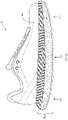
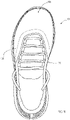
- an article of footwear 10 may be in the form of a running and/or trail shoe including an upper 105 secured to a sole structure 110.
- the shoe 10 generally defines a forefoot region 115, a midfoot region 120, and a hindfoot region 125, as well as a medial side 130 and a lateral side 135.
- the forefoot 115 region generally aligns with the ball and toes of the foot
- the midfoot region 120 generally aligns with the arch and instep areas of the foot
- the hindfoot region 125 generally aligns with the heel and ankle areas of the foot.
- the medial side 130 is the side oriented along the medial (big toe) side of the foot
- the lateral side 135 is the side oriented along the lateral (little toe) side of the foot.
- the upper 105 defines an envelope that covers and protects the foot of the wearer. Accordingly, the upper 105 is formed of any material suitable for its described purpose, including conventional materials (e.g., woven or nonwoven textiles, leather, synthetic leather, rubber, etc.). The specific materials utilized are generally selected to impart wear-resistance, flexibility, air-permeability, moisture control, and comfort to the article of footwear.
- conventional materials e.g., woven or nonwoven textiles, leather, synthetic leather, rubber, etc.
- the specific materials utilized are generally selected to impart wear-resistance, flexibility, air-permeability, moisture control, and comfort to the article of footwear.
- the upper 105 may possess any dimensions (size/shape) suitable for its described purpose.
- the upper 105 may possess a "high top” configuration, in which the hindfoot region 125 of the upper extends over and/or above at least a portion of a user's ankle.
- the upper 105 may possess a "mid top” configuration (in which the upper extends to slightly below or at the user's ankle), a low top configuration, or any other suitable configuration.
- the upper 105 is coupled to the sole structure 110 in any conventional and/or other suitable manner (e.g., via any form of adhesion or bonding, via a woven connection, via one or more types of fasteners, etc.).
- the sole structure 110 includes a conformable assembly adapted to conform to uneven topography as a user travels over the surface.
- the conformable assembly which is oriented toward the bottom (ground-facing side) of the sole structure 110, may include a compression layer and a pliable membrane or outsole coupled to (e.g., mounted on) the compression layer (discussed in greater detail below).
- the outsole moves (flexes) in concert with the compression layer under load.
- the outsole wraps around the sides of the sole structure to define side contact areas along vertical sole surfaces.
- the outsole may further include a plurality of lugs (also referred to herein as traction elements or treads) positioned such that lugs span the bottom and side surfaces of the sole structure.
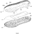
- the sole structure 110 includes a midsole 205, an insert or compression layer 210, and a pliable member or outsole 215 disposed over the insert.
- the article of footwear 10 may further include an insole (not shown) that is disposed within the foot cavity defined by the upper 105 and the sole structure 110.
- the midsole 205 may possess any dimensions (size/shape) suitable for its described purpose.
- the midsole 205 includes a top portion 220A and a bottom portion 220B inset from the top portion along forward, lateral and medial sides to define a shoulder 225 between both portions 220A, 220B.
- the top portion 220A of the midsole 205 includes a top or user-facing surface 230 and a peripheral wall 235 extending around and upward from the midsole top surface 230 that defines an outer peripheral wall surface 240 along the perimeter of the shoe 10.
- the outer surface 240 may be textured, e.g., including a plurality of zigzag lines presented in a repeating pattern.
- the midsole bottom portion 220B generally corresponds with the area of the midsole 205 that couples to (e.g., connects with) the outsole 215, which wraps around the sides of the midsole to define generally vertical side contact areas and a generally horizontal bottom contact area spanning the bottom of the shoe 10 (explained in greater detail below).
- a significant amount (e.g., a majority or substantially all) of the midsole bottom portion 220B is received within the outsole 215 when the midsole 205 is connected with the outsole 215.
- the midsole 205 possesses a generally arcuate or convex transverse cross section. Specifically, the outer surface 240 of the midsole top portion 220A curves outward from the top wall edge 305 to the shoulder 225 (i.e., in the direction of the outsole 215). The outer surface 310 of the midsole bottom portion 220B, moreover, curves inward from the shoulder 225 to the midsole bottom 315. Additionally, as seen best in FIGS. 3A , 3D , and 5A the longitudinal ends of the midsole 305 curve upward.
- the midsole 305 curves upward from the midfoot region 120 toward each of the midsole rearward end 320A and midsole forward end 320B. Stated another way, each of the forefoot region 115 and the hindfoot region 125 curves upward (away from the ground) from the midfoot region 120. With this configuration, the sole possesses a rocker profile along its longitudinal access, which it reduces plantar pressure in the forefoot region.
- the compression layer 210 is loaded along the midsole bottom 315 such that it faces the lower or ground-facing side of the midsole (i.e., the side of the midsole that faces the outsole 215).
- the compression layer 210 comprises an insert received by a cavity 250 formed into midsole bottom 315.
- the cavity 250 defines a recessed area framed by a peripheral wall 255.
- the cavity 250 may possess any dimensions suitable for its described purpose.
- the cavity 250 spans a substantial portion (e.g., over 90%) of the midsole bottom 315, extending from the rear of the hindfoot section 125 to the front of the forefoot section 115.
- the cavity 250 then, possesses dimensions (e.g., size/shape) that substantially conform to the dimensions (e.g., size and shape) of the insert 210 (the insert is discussed in greater detail, below).
- the depth of the cavity 250 is generally equal to the thickness (height) of the insert 210 such that the insert, when positioned within the cavity, is generally flush with surface of the midsole bottom 315 (e.g., a bottom surface 260 of the insert 210 is generally flush or co-planar with the midsole bottom 315 when the insert 210 is fit within cavity 250, as seen best in FIG. 3B ).
- One or more elongated holes or apertures 265 may be formed into midsole bottom portion 220B, the apertures being such that they are generally located within the cavity 250. As seen best in FIGS. 5A, 5B, and 5C , the apertures 265 extend partially through the thickness of the midsole material (i.e., the apertures do not extend completely through the midsole). In an embodiment, the apertures 265 extend approximately half way through the thickness of the midsole 205. The apertures 265 are provided within the midsole 205 to remove midsole material so as to reduce the weight of the midsole.
- any selected number, spacing, geometric configurations (e.g., round shaped, triangular or polygon shaped, etc.) and one or more patterns of apertures 265 can be provided along the lower surface 315 (including within or distanced from the cavity 250) of the midsole 205 to achieve a weight reduction of the midsole for a particular embodiment.
- one or more groups clusters of apertures 265 can be defined at different regions or locations of the midsole bottom 315 (e.g., along the medial side, the lateral side, the forefoot region, midfoot region, or hindfoot region), where the number of apertures per area can be different from clusters of apertures located at different locations.
- the cross-sectional shapes and/or dimensions (e.g., diameters and/or depths) of the apertures 265 can also be varied at different locations along the midsole 205.
- the midsole 205 may further include a notch 270 disposed within its hindfoot region 125 that is oriented proximate the shoe longitudinal axis.
- the notch 270 is defined by a groove that extends from the top edge 305 to the midsole bottom 315, traversing both the midsole top portion 220A and the midsole bottom portion 220B.
- the notch 270 aligns with a corresponding notch formed into the pliable member 215 (discussed in greater detail below).
- the midsole may also include an electronics cavity 272 formed into the top (user facing) surface of the midsole.
- the electronic cavity may house an electronics module (e.g., a sensor suite comprising one or more sensors that track movement, distance, etc.).
- the midsole 205 is formed of a first material having a first compression value, e.g., compression strength, compression modulus, and/or durometer value.
- a compression value measures the compressibility, resiliency and/or recovery of a material in response to a load or a force being exerted upon the material. Any one or more compression tests can be performed to provide a compression value for the material.
- One example of a compression test is a measurement of elastic modulus (i.e., a ratio of stress applied to the material to strain of the material).
- Another example of a compression test is a hardness of the material in durometers (measurement of the resistance of a material to permanent indentation), measured utilizing a Shore A Hardness scale.
- the midsole 205 may be formed of a material having a Shore A durometer of approximately 40 - 50.
- the midsole 10 may be formed of ethylene vinyl-acetate foam having a Shore A durometer of approximately 40 - 50 (e.g., 45 Shore A).
- the first material may be foam including ethylene-vinyl acetate blended with one or more of an EVA modifier, a polyolefin block copolymer, and a triblock copolymer.
- the EVA blend may possess a Shore A durometer of approximately 40 - 50 (e.g., 45 Shore A).
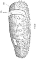
- the compression layer or insert 210 is configured to compress upon contact with a surface object and/or to compress vertically upward (toward the midsole) under load.
- the insert 210 may be in the form of a generally planar member having a substantially uniform thickness.
- the insert 210 possesses a thickness that is approximately one half to one third the thickness of the corresponding midsole section (the section directly above the insert, measured from the ceiling of the cavity 250 to the midsole top surface 230).
- the insert 210 may be approximately 6 mm thick.
- the insert 210 may possess any dimensions (size/shape) suitable for its described purpose. As shown, the insert 210 possesses dimensions (size/shape) similar that of the midsole cavity 250, with the insert being slightly smaller to enable insertion into the cavity. The shape, as well as the length and width dimensions of the insert 210 may generally conform to the midsole cavity 250 such that any lengthwise or lateral movements of the insert in relation to the midsole 205 are significantly limited after insertion of the insert into cavity.
- the insert 210 can be secured within the cavity 250 of the midsole 305 via any suitable technique (e.g., adhesive bonding). Alternatively, the insert 210 may simply be placed within the cavity 250 prior to securing of the midsole 305 with the outsole 215 as described herein, where the insert is frictionally held in place within the midsole cavity prior to assembly with the outsole.
- the insert 210 is formed of a second material having a second compression value, e.g., compression strength, compression modulus, and/or durometer value.
- the insert 210 may be formed of material having a lower compression strength (measured via indentation force deflection) than the first material compression strength.
- the second material may possess a durometer value that is lower than the durometer value of the first material durometer value.
- the durometer value of the insert 210 is approximately one-half to three-fourths the value of the first material durometer value.
- the second material possesses a durometer (Shore A) of approximately 20 - 30 (e.g., 25 Shore A).
- the insert 310 is formed of ethylene vinyl acetate foam possessing a Shore A durometer of 25.
- the pliable membrane or outsole 215 is a pliable, wear-resistant membrane coupled to the bottom portion 220B of the midsole 205.
- the outsole 215 should be formed of material that, while flexible, provides desired traction (e.g., coefficient of friction), wear-resistance, and durability. Examples of suitable outsole materials are elastomers, siloxanes, natural rubber, and synthetic rubber.
- the outsole is a rubber material commercially available from MICHELIN (Clermont-Ferrand, France), such as a rubber material commercially available from MICHELIN and provided under the tradename WILD GRIPPER or WILD GRIP'R.
- the outsole 215 is molded as a single component.
- the outsole 215 may possess any dimensions (size/shape) suitable for its described purpose.
- the base thickness of the outsole (the thickness not considering the lugs or traction elements) should be effective to permit flexure of the membrane along the area in contact with the insert 210.
- the base thickness of the outsole 215 (in a non-lug-containing area) may be less than approximately 2.0 mm (e.g., approximately 1.0 - 1.5 mm).
- the thickness of the outsole including a lug is approximately 2.5 - 6.5 mm.
- the outsole 215 is suitably dimensioned to receive the midsole bottom portion 220B. Referring to FIGS. 2A - 2C and FIG.
- the outsole 215 may be generally concave or trough-shaped, including a floor or bottom 275 with a generally vertical sidewall 280 extending distally (upward) from the floor. With this configuration, the outsole 215 may cover the entire bottom of the midsole 205, wrapping around the side of the midsole to define an interior (user- or midsole-facing) surface 285A and an exterior or ground-facing surface 285B.
- the outsole 215 further includes a cut-out section or notch 290 operable to align with the midsole notch 270 (best seen in FIG. 2D ).
- the notches 270, 290 cooperate to provide the sole structure with several benefits.
- the notches 270, 290 facilitate easy manufacture of each of the midsole 205 and outsole 215 (e.g., easier to remove from mold in a molding manufacture process).
- the notches 270, 290 can facilitate easier assembly of the midsole 205 with the outsole 215 (e.g., by aligning the notches when inserting the midsole into the outsole).
- the notches 270, 290 can be configured to provide a decoupling or deflection property to the hindfoot region 125 of the sole structure 110 (i.e., the sole structure portion located at the heel of the shoe 10), where a portion of the medial side 130 of the sole structure 110 (i.e., a portion of the sole structure located along the medial side 130 of the shoe 10) extending to the heel side of the sole structure is decoupled and thus is free to deflect or move slightly independently from a portion of the lateral side 135 of the sole structure 10 (i.e., a portion of the sole structure located along the lateral side 135 of the shoe 10) extending to the heel side.
- the notches 270, 290 cooperate to provide an aesthetic feature to the outsole, providing visual interest.
- the outsole exterior surface 385B (i.e., the ground engaging surface of the outsole) may include one or more lugs or tread elements 605 extending distally from the exterior surface, being disposed in a predetermined pattern about the outsole.
- Each lug 605 may possess any dimensions (size/shape) suitable for its described purpose (to provide traction).
- the lugs 605, moreover, may be oriented into regions or zones along the outsole 215.
- the outsole exterior surface 385B includes a central traction zone 615 disposed centrally along the bottom 620 of the outsole 215.
- a lateral traction zone 625 is disposed along the lateral side 135 of the outsole 215, extending from the outsole bottom 620 to the outsole side wall 630.
- a medial traction zone 635 is disposed along the medial side of the outsole 215, extending from the outsole bottom 620 to the outsole side wall 630.
- a forward traction zone 645 is disposed along the front of the forefoot region, spanning the outsole bottom 620 and side wall 630.
- a rearward traction zone 655 is disposed along the rear of the hindfoot region 125, extending from the outsole bottom 620 to the side wall 630.
- the density of lugs 605 may differ within each traction zone 615, 625, 635, 645, 655.
- the density of lugs 605 within the forward traction zone 645 and the rearward traction zone 655 is greater than the density of lugs in each of the central 615, lateral 625, and medial 635 traction zones. In the high density areas, the lugs 605 are spaced closer together.
- the clustering of lugs 605 in this manner is effective to enhance the overall traction of the outsole 215 by providing greater traction at points of greatest need, namely, at the points of propulsion, which occur along the front and back areas of the sole structure 110 (i.e., the contact/push-off points at heel strike and toe-off during the running gait cycle).
- the height of the lugs 605 may be selected to improve overall traction performance.
- the lugs 605 of the central traction zone 615 may possess a first height h1 (i.e., a lengthwise dimension extending from the ground engaging surface of the outsole) while the lugs of the remaining traction zones 625, 635, 645, 655 may possess a second height h2, with the second height being greater than the first height.
- the first height h1 may be approximately 1.5 - 3.0 mm
- the second height h2 may be approximately 3 - 5 mm.
- the lugs 605 may be disposed on the outsole bottom 620, wrapping around to the side wall 630 of the outsole. Specifically, the lugs 605 (e.g., the lugs of the lateral 625, medial 635, forward 345, and rearward 655 traction zones) protrude from the outsole side wall 630, terminating proximate the midsole top portion 220A. With this configuration, the lugs 605 are directed in multiple directions (downward, forward, rearward, laterally, and medially), providing omnidirectional traction, which is beneficial when trail running.
- the lugs 605 e.g., the lugs of the lateral 625, medial 635, forward 345, and rearward 655 traction zones protrude from the outsole side wall 630, terminating proximate the midsole top portion 220A.
- the lugs 605 are directed in multiple directions (downward, forward, rearward, laterally, and medially), providing omnidirectional traction, which is
- the cross slope grip of the outsole is improved. That is, the clustering/sizing of lugs 605 and/or their positioning along the sides of the sole structure can facilitate cross rocker traction of the shoe, providing an enhanced gripping surface for the outsole 215 in a variety of different directions along the outsole. That is, the lugs 605 along the outsole bottom 620 are oriented generally orthogonal to a support surface, while the lugs along the side 630 are oriented at an angle generally between 90° and 180° with respect to the support surface. Thus, 180° of traction is provided, enabling traction along not only the horizontal running surface, but along any vertical surfaces contacted during use.
- the sole structure 110 possesses varying degrees of compression along its bottom surface. That is, the sole structure (as defined by the outsole bottom 620) includes multiple compression zones in the transverse and/or longitudinal shoe directions. Referring to FIG. 7 , the outsole bottom 620 includes a first, peripheral compression zone 710 and a second, interior compression zone 715.
- the first compression zone 710 including the first material of the midsole 205, experiences less compression under the same load, thus functions to stabilize the shoe during the gait cycle.
- the first compression zone 710 being defined by the midsole cavity wall 250, defines a frame or border surrounding the lateral edges of the second compression zone 715. The border may be of uniform thickness or, as illustrated in FIG.
- the second compression zone 715 is an interior compression zone that defines a region including or aligned with a significant portion (e.g., a majority or all) of the insert 210 (formed of the second material) and is bordered by the first compression zone 710 (i.e., the second compression zone is inset from the edges of the bottom side 350).
- the second compression zone 715 is generally centrally located along the outsole bottom 620, beginning proximate the rear midsole end 320A and extending continuously from the hindfoot region 125, across the midfoot region 120 and into the forefoot region 115, terminating proximate the forward midsole end 320B.
- the second compression zone 710 In the transverse dimension, the second compression zone 710 generally spans the width of the midsole 205 beginning proximate the lateral shoe side 135 and terminating proximate the medial shoe side 130.
- the peripheral zone 710 defines an outer compression zone that generates lateral, medial, forefoot, and hindfoot support, while the interior zone 715 (being spaced from all the edges of the midsole bottom side) generates improved contact with the running surface because it conforms to uneven topography.
- These zones 710, 715 cooperate to provide the shoe 10 (e.g., a trail/outdoor running shoe) with improved stability compared to shoes lacking these zones (explained in greater detail, below).
- the sole structure 110 includes a high compression region along the interface between the outsole and insert, as well as a low compression region along the interface between the outsole and the midsole 205 (the bottom surface 315 of midsole).
- the low compression region surrounds the high compression region, providing support for the user as the article of footwear travels over a level surface.
- the lugs 605 that contact the element protruding from the surface are urged inward (under the weight of the wearer), toward the user.
- the lugs 605 are driven into the cavity at a distance equal to the height of the protruding element or the depth of the cavity.
- the lug 605 is driven/retracted into the cavity 250 within the high compression region, while the low compression region remains in contact with the ground.
- the system maintains contact between outsole 215 and the surface, but contours to the topography of the surface, improving traction as the user runs over the surface.
- the features of the insert 210 and midsole 205 being constructed of different compressive or foam materials, where the insert is a softer or more compressible material, and the placement of these components within the sole structure 110 provides a bottom cushioning or bottom loading effect for the shoe 10.
- the midsole 205 and insert 210 compress, where the insert 210 is softer and thus compresses to a greater degree than the midsole 205 so as to provide a greater cushioning to the user's foot beneath the midsole 205.
- the insert 210 since the insert 210 is separate from the midsole 205, the insert 210 provides a separate and independent suspension for the user's foot during use of the shoe 10. That is, the high compression area of the shoe will selectively compress depending on the topography.
- the bottom cushioning or bottom loading configuration of the sole structure 110 is particularly useful for implementation in a running shoe for uneven surfaces, including terrains with rocks, loose dirt, gravel, etc.
- the sole structure 110 is configured to conform to an uneven surface, particularly in the region that includes the insert 210.
- the midsole conforms or compresses to a lesser extent to the uneven surface compared with the insert.
- the compression of the insert 210 due to an uneven terrain is not translated or translated to a lesser degree to the midsole 205, resulting in a buffering effect in which the user feels little or no impact caused by the uneven surface on his or her foot.
- treads 605 along the exterior outsole surface 285B, along both the outsole bottom 620 and sidewall 630 enhance the gripping action of the shoe, providing cross rocker traction or an enhanced gripping surface for the outsole in a variety of different directions along the outsole. This is particularly useful for applications (running, jogging, walking, hiking, etc.) on uneven terrains.
- the bulbous or arcuate exterior profile of the sole structure 110 along its entire exterior periphery enhances traction of the shoe 110 for such applications since there is an increase in traction surface area provided by the shoe 110 (i.e., the traction surface area for the shoe 110 is provided not only on the lower or tread surface of the outsole 215 but also along the external periphery of the sole structure 110).
- the bulbous or arcuate exterior profile of the sole structure 110 can extend along toe, heel, medial and lateral sides of the article of footwear such that the arcuate profile extends outward beyond an exterior sidewall periphery of the upper along at least one of the toe, heel, medial and lateral sides of the article of footwear (this can be seen, e.g., in FIGs. 1A and 1B ).
- the insert 210 is fit within the cavity 250 of the midsole 205 (where the insert can optionally be secured by adhesion bonding or other suitable method to the midsole).
- the midsole 205, with insert 210 disposed in cavity 250, is secured within the concave interior surface of the outsole 215 such that at least portions of the bottom surface 315 of the midsole engage with corresponding portions of the outsole interior surface 285B.
- the midsole 205 can be secured to the outsole 215 (e.g., via adhesive bonding) at any one or more contact point locations between the midsole and outsole, resulting in the sole structure 110 depicted in the figures.
- the sole structure 110 includes the insert 210 disposed or sandwiched between the midsole 205 and outsole 215 while also being fit (partially or entirely) within the midsole cavity 250.
- the upper 105 is then secured to the midsole 205 to form the shoe 10.
- the cavity may possess any dimensions (size and/or shape) suitable for its described purpose. While a cavity spanning a substantial surface area of the is illustrated, it should be understood that lesser cavities may be provided, e.g., a cavity disposed in only the forefoot region 115, a cavity disposed in only the midfoot region 120, and/or a cavity disposed in only the hindfoot region 120. A combination of the aforesaid may also be provided.
- Each of the midsole 205 and the insert 210 are constructed of a suitable compression or foam material, where the midsole and insert can each be formed in a mold as a single component.
- the foam material for each of the midsole and insert cooperate to compress together in response to an applied load or force and also exhibits a suitable recovery or expansion in response to removal of the force.
- the midsole 205 and insert 210 are formed of different foam materials having different degrees of compression, where the insert is a softer and thus more compressible foam material which also has a greater rebound in relation to the midsole.
- the configuration of the sole structure 110 including configuration and different types of foam materials provided for each of the midsole and insert, provides a bottom loading of the softer insert in relation to the midsole for the sole structure.
- ethylene vinyl acetate foams While softer and harder ethylene vinyl acetate foams are specifically discussed, it should be understood that other compression materials may be utilized, including olefin or polyolefin foam, PU foam, urethane based foam, thermoplastic foam, or other polymer foam, rubber, elastomer, or other material with suitable shock absorbing characteristics.
- treads 605 can be provided at any suitable portions of the outsole peripheral sidewall 630 so as to enhance the gripping action of the shoe in use for particular applications.
Landscapes
- Chemical & Material Sciences (AREA)
- Engineering & Computer Science (AREA)
- Materials Engineering (AREA)
- Footwear And Its Accessory, Manufacturing Method And Apparatuses (AREA)
Description
- The present invention relates to an article of footwear and, in particular, to a trail running shoe with sole structure including a high compression region oriented toward the bottom of the structure.
- There are many different types of footwear available for uses related to specific types of activity, such as running, hiking, working, etc. For example, there are numerous types of footwear associated with physical activities, in particular outdoor activities involving walking, jogging or running in a variety of different terrains, where the footwear is provided with different features to provide comfort to a user while engaging in such activities.
- Comfort and stability features associated with footwear for running and jogging (which is typically associated with providing adequate support for relatively flat and/or even surfaces such as paved roads or walkways) can be different in comparison to features associated with footwear for hiking in more rugged terrain (for example, paths that are not paved or are typically associated with uneven surfaces). However, it would be desirable to provide a footwear product that combines comfort and stability features for a user engaging in walking, running and/or jogging on hiking trails and other uneven surfaces.
- With regard to the prior art attention is drawn to
US 2011/179669 A1 from which a midsole adapted for attachment to a shoe having multiple layers of varying materials each having a different hardness level is known. More particularly, the present midsole includes a top, middle and bottom layer wherein all three layers of material have a different hardness range and wherein at least one of the layers is made from thermoplastic rubber (TPR). In one embodiment, the thermoplastic rubber (TPR) layer lies between the top and bottom layers and in another embodiment, the thermoplastic rubber (TPR) layer is the bottom layer. The thermoplastic rubber (TPR) layer may also have a length shorter than the other two layers forming the midsole. - From
WO 2011/043507 A1 a three-stage cushioned sole is known, which shows excellent three-stage cushioning through the sequential adhesion of first and second cushions with different hardness to a heel portion of a main body of a sole. In addition, a shank installed at the main body of a sole is separated into front and back shanks, insertion portions in the shape of a hand in which a finger portion and a valley portion are each repeatedly formed are formed at a portion where the front and back shanks face each other, and the insertion portions of the front and back shanks are engaged with each other, thereby enabling the stimulation of acupuncture points of the foot sole by the protrusions formed at the finger portion during walking. - Further, from
EP 2 574 251 A2 an article of footwear is known, having a molded outsole which contains a resilient midsole located in the cavity of the outsole and a footbed cover which has a stretch material layer affixed to the outsole and provides a stretch zone. The stretch zone allows the footbed cover to work in conjunction with the resilient midsole to absorb shock upon heel strike or other compression of the midsole to increase comfort. Preferably, the midsole has sections of different hardness in the heel area and the forefoot area. - Furthermore, from
US 2005/268490 A1 an article of footwear is known that incorporates an upper and a sole structure secured to the upper. The sole structure includes a midsole and an outsole. The midsole defines an aperture with a first sidewall, and the midsole includes an insert positioned within the aperture. The insert has a second sidewall, with at least a portion of the second sidewall being spaced from the first sidewall to define a space between the first sidewall and the second sidewall. The outsole is secured to the midsole, and the outsole defines a ridge that is positioned within a lower portion of the space and between the first sidewall and the second sidewall. - The present invention relates to a sole structure for an article of footwear as defined in claim 1.
- Preferred embodiments of the invention are disclosed in the dependent claims.
- An article of footwear includes an upper and a sole structure including conformable material oriented toward the bottom of the structure. Specifically, the sole structure includes a midsole formed of material having a first compression value. The bottom of the midsole is loaded with a material having a second compression value that differs from the first compression value. In an embodiment, the midsole includes a cavity disposed along its bottom (ground-facing) side that receives an insert formed of the material possessing a second compression value. The insert material is softer, possessing a lower durometer value than the midsole material. An outsole formed of pliable material covers the insert. With this configuration, the sole structure is adapted to conform to uneven topography such that, upon contact with an irregular surface under load, the sole bottom conforms to the surface without interference to the wearer.
-
-
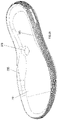
FIG. 1A illustrates a side view in elevation of an article of footwear including a sole structure in accordance with an embodiment of the present invention. -
FIG. 1B illustrates a top view in plan of the article of footwear ofFIG. 1A . -
FIG. 2A illustrates a side perspective view of the sole structure shown in isolation (lateral side illustrated). -
FIG. 2B is an exploded top view of the sole structure for the article of footwear shown inFIG. 2A . -
FIG. 2C is an exploded bottom view of the sole structure for the article of footwear shown inFIG. 2A . -
FIG. 2D is a rear perspective view of the sole structure shown inFIG. 2A . -
FIG. 3A illustrates a top perspective view of a midsole in accordance with the present invention, shown in isolation. -
FIG. 3B illustrates a bottom perspective view of the midsole shown inFIG. 3A . -
FIG. 3C illustrates a rear view in elevation of the midsole shown inFIG. 3A . -
FIG. 3D is a side view in elevation of the midsole shown inFIG. 3A . -
FIG. 3E is a bottom perspective view of the midsole shown inFIG. 3A . -
FIG. 4A illustrates a bottom plan view of the sole structure in accordance with the present invention. -
FIG. 4B illustrates is an elevated side view of the sole structure shown inFIG. 4A , showing the medial side of the sole structure. -
FIG. 4C illustrates a rear view in elevation of the sole structure shown inFIG. 4A . -
FIG. 4D illustrates a front view in elevation of the sole structure shown inFIG. 4A . -
FIG. 5A illustrates a cross sectional view taken alonglines 5A - 5A inFIG. 4A . -
FIG. 5B illustrates a cross sectional view taken alonglines 5B - 5B inFIG. 4A . -
FIG. 5C illustrates a cross sectional view taken alonglines 5C - 5C inFIG. 4A . -
FIG. 6A illustrates a bottom view in perspective of the sole structure in accordance with an embodiment of the invention. -
FIG. 6B illustrates a bottom plan view of the sole structure ofFIG. 6A , schematically showing various lug zones. -
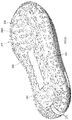
FIG. 7 is a bottom plan view of the sole structure in accordance with an embodiment of the invention, schematically showing various compression zones. -
FIG. 8 illustrates a view in perspective of the insert or compression layer of the sole structure ofFIG. 2A . -
FIG. 9 is a front perspective view of the outsole, shown in isolation. - Like reference numerals have been used to identify like elements throughout this disclosure.
- As described herein with reference to
FIGS. 1 - 9 , an article of footwear includes an upper coupled to a sole structure configured to selectively conform to a surface of uneven topography. In an embodiment, the sole structure includes a midsole, a compression plate or insert that fits at least partially within a cavity defined along an underside of the midsole, and an outsole that receives the midsole such that the insert is located between the midsole and outsole. The midsole is formed of a first material (also referred to herein as a first compression material or a first compressible material) having a first degree of compression, while the insert is formed of a second material (also referred to herein as a second compression material or a second compressible material) having a second, different degree of compression. - Referring to
FIGS. 1A and1B , an article of footwear 10 (also called a shoe) may be in the form of a running and/or trail shoe including an upper 105 secured to asole structure 110. Theshoe 10 generally defines aforefoot region 115, amidfoot region 120, and ahindfoot region 125, as well as amedial side 130 and alateral side 135. Theforefoot 115 region generally aligns with the ball and toes of the foot, themidfoot region 120 generally aligns with the arch and instep areas of the foot, and thehindfoot region 125 generally aligns with the heel and ankle areas of the foot. Themedial side 130 is the side oriented along the medial (big toe) side of the foot, while thelateral side 135 is the side oriented along the lateral (little toe) side of the foot. - The upper 105 defines an envelope that covers and protects the foot of the wearer. Accordingly, the upper 105 is formed of any material suitable for its described purpose, including conventional materials (e.g., woven or nonwoven textiles, leather, synthetic leather, rubber, etc.). The specific materials utilized are generally selected to impart wear-resistance, flexibility, air-permeability, moisture control, and comfort to the article of footwear.
- Additionally, the upper 105 may possess any dimensions (size/shape) suitable for its described purpose. For example, the upper 105 may possess a "high top" configuration, in which the
hindfoot region 125 of the upper extends over and/or above at least a portion of a user's ankle. Alternatively, the upper 105 may possess a "mid top" configuration (in which the upper extends to slightly below or at the user's ankle), a low top configuration, or any other suitable configuration. The upper 105 is coupled to thesole structure 110 in any conventional and/or other suitable manner (e.g., via any form of adhesion or bonding, via a woven connection, via one or more types of fasteners, etc.). - The
sole structure 110 includes a conformable assembly adapted to conform to uneven topography as a user travels over the surface. The conformable assembly, which is oriented toward the bottom (ground-facing side) of thesole structure 110, may include a compression layer and a pliable membrane or outsole coupled to (e.g., mounted on) the compression layer (discussed in greater detail below). The outsole moves (flexes) in concert with the compression layer under load. In an embodiment, the outsole wraps around the sides of the sole structure to define side contact areas along vertical sole surfaces. The outsole may further include a plurality of lugs (also referred to herein as traction elements or treads) positioned such that lugs span the bottom and side surfaces of the sole structure. - Referring to
FIGS. 2A ,2B ,2C , and2D thesole structure 110 includes amidsole 205, an insert orcompression layer 210, and a pliable member oroutsole 215 disposed over the insert. The article offootwear 10 may further include an insole (not shown) that is disposed within the foot cavity defined by the upper 105 and thesole structure 110. Themidsole 205 may possess any dimensions (size/shape) suitable for its described purpose. Themidsole 205 includes atop portion 220A and abottom portion 220B inset from the top portion along forward, lateral and medial sides to define ashoulder 225 between bothportions top portion 220A of themidsole 205 includes a top or user-facingsurface 230 and aperipheral wall 235 extending around and upward from the midsoletop surface 230 that defines an outerperipheral wall surface 240 along the perimeter of theshoe 10. Theouter surface 240 may be textured, e.g., including a plurality of zigzag lines presented in a repeating pattern. - The
midsole bottom portion 220B generally corresponds with the area of themidsole 205 that couples to (e.g., connects with) theoutsole 215, which wraps around the sides of the midsole to define generally vertical side contact areas and a generally horizontal bottom contact area spanning the bottom of the shoe 10 (explained in greater detail below). In an example embodiment a significant amount (e.g., a majority or substantially all) of themidsole bottom portion 220B is received within theoutsole 215 when themidsole 205 is connected with theoutsole 215. - As best seen in
FIGS. 3B ,3C ,5B and5C , themidsole 205 possesses a generally arcuate or convex transverse cross section. Specifically, theouter surface 240 of the midsoletop portion 220A curves outward from thetop wall edge 305 to the shoulder 225 (i.e., in the direction of the outsole 215). Theouter surface 310 of themidsole bottom portion 220B, moreover, curves inward from theshoulder 225 to themidsole bottom 315. Additionally, as seen best inFIGS. 3A ,3D , and5A the longitudinal ends of themidsole 305 curve upward. Specifically, themidsole 305 curves upward from themidfoot region 120 toward each of the midsole rearwardend 320A and midsole forward end 320B. Stated another way, each of theforefoot region 115 and thehindfoot region 125 curves upward (away from the ground) from themidfoot region 120. With this configuration, the sole possesses a rocker profile along its longitudinal access, which it reduces plantar pressure in the forefoot region. - Referring back to
FIGS. 2A - 2D , thecompression layer 210 is loaded along themidsole bottom 315 such that it faces the lower or ground-facing side of the midsole (i.e., the side of the midsole that faces the outsole 215). In an embodiment, thecompression layer 210 comprises an insert received by acavity 250 formed intomidsole bottom 315. As shown, thecavity 250 defines a recessed area framed by aperipheral wall 255. Thecavity 250 may possess any dimensions suitable for its described purpose. In the embodiment illustrated, thecavity 250 spans a substantial portion (e.g., over 90%) of themidsole bottom 315, extending from the rear of thehindfoot section 125 to the front of theforefoot section 115. Thecavity 250, then, possesses dimensions (e.g., size/shape) that substantially conform to the dimensions (e.g., size and shape) of the insert 210 (the insert is discussed in greater detail, below). In an embodiment, the depth of thecavity 250 is generally equal to the thickness (height) of theinsert 210 such that the insert, when positioned within the cavity, is generally flush with surface of the midsole bottom 315 (e.g., abottom surface 260 of theinsert 210 is generally flush or co-planar with themidsole bottom 315 when theinsert 210 is fit withincavity 250, as seen best inFIG. 3B ). - One or more elongated holes or
apertures 265 may be formed intomidsole bottom portion 220B, the apertures being such that they are generally located within thecavity 250. As seen best inFIGS. 5A, 5B, and 5C , theapertures 265 extend partially through the thickness of the midsole material (i.e., the apertures do not extend completely through the midsole). In an embodiment, theapertures 265 extend approximately half way through the thickness of themidsole 205. Theapertures 265 are provided within themidsole 205 to remove midsole material so as to reduce the weight of the midsole. Any selected number, spacing, geometric configurations (e.g., round shaped, triangular or polygon shaped, etc.) and one or more patterns ofapertures 265 can be provided along the lower surface 315 (including within or distanced from the cavity 250) of themidsole 205 to achieve a weight reduction of the midsole for a particular embodiment. For example, one or more groups clusters ofapertures 265 can be defined at different regions or locations of the midsole bottom 315 (e.g., along the medial side, the lateral side, the forefoot region, midfoot region, or hindfoot region), where the number of apertures per area can be different from clusters of apertures located at different locations. The cross-sectional shapes and/or dimensions (e.g., diameters and/or depths) of theapertures 265 can also be varied at different locations along themidsole 205. - The
midsole 205 may further include anotch 270 disposed within itshindfoot region 125 that is oriented proximate the shoe longitudinal axis. Thenotch 270 is defined by a groove that extends from thetop edge 305 to themidsole bottom 315, traversing both the midsoletop portion 220A and themidsole bottom portion 220B. Thenotch 270 aligns with a corresponding notch formed into the pliable member 215 (discussed in greater detail below). - The midsole may also include an
electronics cavity 272 formed into the top (user facing) surface of the midsole. The electronic cavity may house an electronics module (e.g., a sensor suite comprising one or more sensors that track movement, distance, etc.). - The
midsole 205 is formed of a first material having a first compression value, e.g., compression strength, compression modulus, and/or durometer value. A compression value measures the compressibility, resiliency and/or recovery of a material in response to a load or a force being exerted upon the material. Any one or more compression tests can be performed to provide a compression value for the material. One example of a compression test is a measurement of elastic modulus (i.e., a ratio of stress applied to the material to strain of the material). Another example of a compression test is a hardness of the material in durometers (measurement of the resistance of a material to permanent indentation), measured utilizing a Shore A Hardness scale. - In an embodiment, the
midsole 205 may be formed of a material having a Shore A durometer of approximately 40 - 50. Specifically, themidsole 10 may be formed of ethylene vinyl-acetate foam having a Shore A durometer of approximately 40 - 50 (e.g., 45 Shore A). In another embodiment, the first material may be foam including ethylene-vinyl acetate blended with one or more of an EVA modifier, a polyolefin block copolymer, and a triblock copolymer. As with the pure EVA, the EVA blend may possess a Shore A durometer of approximately 40 - 50 (e.g., 45 Shore A). - The compression layer or insert 210 is configured to compress upon contact with a surface object and/or to compress vertically upward (toward the midsole) under load. As shown in
FIG. 8 , theinsert 210 may be in the form of a generally planar member having a substantially uniform thickness. In an embodiment, theinsert 210 possesses a thickness that is approximately one half to one third the thickness of the corresponding midsole section (the section directly above the insert, measured from the ceiling of thecavity 250 to the midsole top surface 230). By way of specific example, theinsert 210 may be approximately 6 mm thick. - It should be understood, however, that the
insert 210 may possess any dimensions (size/shape) suitable for its described purpose. As shown, theinsert 210 possesses dimensions (size/shape) similar that of themidsole cavity 250, with the insert being slightly smaller to enable insertion into the cavity. The shape, as well as the length and width dimensions of theinsert 210 may generally conform to themidsole cavity 250 such that any lengthwise or lateral movements of the insert in relation to themidsole 205 are significantly limited after insertion of the insert into cavity. Theinsert 210 can be secured within thecavity 250 of themidsole 305 via any suitable technique (e.g., adhesive bonding). Alternatively, theinsert 210 may simply be placed within thecavity 250 prior to securing of themidsole 305 with theoutsole 215 as described herein, where the insert is frictionally held in place within the midsole cavity prior to assembly with the outsole. - The
insert 210 is formed of a second material having a second compression value, e.g., compression strength, compression modulus, and/or durometer value. By way of example, theinsert 210 may be formed of material having a lower compression strength (measured via indentation force deflection) than the first material compression strength. By way of further example, the second material may possess a durometer value that is lower than the durometer value of the first material durometer value. In an embodiment, the durometer value of theinsert 210 is approximately one-half to three-fourths the value of the first material durometer value. By way of specific example, the second material possesses a durometer (Shore A) of approximately 20 - 30 (e.g., 25 Shore A). In an embodiment, theinsert 310 is formed of ethylene vinyl acetate foam possessing a Shore A durometer of 25. - The pliable membrane or
outsole 215 is a pliable, wear-resistant membrane coupled to thebottom portion 220B of themidsole 205. Theoutsole 215 should be formed of material that, while flexible, provides desired traction (e.g., coefficient of friction), wear-resistance, and durability. Examples of suitable outsole materials are elastomers, siloxanes, natural rubber, and synthetic rubber. By way of specific example, the outsole is a rubber material commercially available from MICHELIN (Clermont-Ferrand, France), such as a rubber material commercially available from MICHELIN and provided under the tradename WILD GRIPPER or WILD GRIP'R. In an embodiment, theoutsole 215 is molded as a single component. - The
outsole 215 may possess any dimensions (size/shape) suitable for its described purpose. The base thickness of the outsole (the thickness not considering the lugs or traction elements) should be effective to permit flexure of the membrane along the area in contact with theinsert 210. For example, the base thickness of the outsole 215 (in a non-lug-containing area) may be less than approximately 2.0 mm (e.g., approximately 1.0 - 1.5 mm). The thickness of the outsole including a lug is approximately 2.5 - 6.5 mm. Theoutsole 215 is suitably dimensioned to receive themidsole bottom portion 220B. Referring toFIGS. 2A - 2C andFIG. 9 , theoutsole 215 may be generally concave or trough-shaped, including a floor or bottom 275 with a generallyvertical sidewall 280 extending distally (upward) from the floor. With this configuration, theoutsole 215 may cover the entire bottom of themidsole 205, wrapping around the side of the midsole to define an interior (user- or midsole-facing)surface 285A and an exterior or ground-facingsurface 285B. - The
outsole 215 further includes a cut-out section or notch 290 operable to align with the midsole notch 270 (best seen inFIG. 2D ). Thenotches notches midsole 205 and outsole 215 (e.g., easier to remove from mold in a molding manufacture process). In addition, thenotches midsole 205 with the outsole 215 (e.g., by aligning the notches when inserting the midsole into the outsole). Further, thenotches hindfoot region 125 of the sole structure 110 (i.e., the sole structure portion located at the heel of the shoe 10), where a portion of themedial side 130 of the sole structure 110 (i.e., a portion of the sole structure located along themedial side 130 of the shoe 10) extending to the heel side of the sole structure is decoupled and thus is free to deflect or move slightly independently from a portion of thelateral side 135 of the sole structure 10 (i.e., a portion of the sole structure located along thelateral side 135 of the shoe 10) extending to the heel side. Finally, thenotches - Referring to
FIG. 6A , the outsole exterior surface 385B (i.e., the ground engaging surface of the outsole) may include one or more lugs or treadelements 605 extending distally from the exterior surface, being disposed in a predetermined pattern about the outsole. Eachlug 605 may possess any dimensions (size/shape) suitable for its described purpose (to provide traction). Thelugs 605, moreover, may be oriented into regions or zones along theoutsole 215. Referring toFIG. 6B , the outsole exterior surface 385B includes acentral traction zone 615 disposed centrally along thebottom 620 of theoutsole 215. Alateral traction zone 625 is disposed along thelateral side 135 of theoutsole 215, extending from theoutsole bottom 620 to theoutsole side wall 630. Similarly, amedial traction zone 635 is disposed along the medial side of theoutsole 215, extending from theoutsole bottom 620 to theoutsole side wall 630. Aforward traction zone 645 is disposed along the front of the forefoot region, spanning theoutsole bottom 620 andside wall 630. Finally, arearward traction zone 655 is disposed along the rear of thehindfoot region 125, extending from theoutsole bottom 620 to theside wall 630. - The density of lugs 605 (i.e., the number of lugs within a traction zone) may differ within each
traction zone FIG. 6B , the density oflugs 605 within theforward traction zone 645 and therearward traction zone 655 is greater than the density of lugs in each of the central 615, lateral 625, and medial 635 traction zones. In the high density areas, thelugs 605 are spaced closer together. The clustering oflugs 605 in this manner is effective to enhance the overall traction of theoutsole 215 by providing greater traction at points of greatest need, namely, at the points of propulsion, which occur along the front and back areas of the sole structure 110 (i.e., the contact/push-off points at heel strike and toe-off during the running gait cycle). - The height of the
lugs 605 may be selected to improve overall traction performance. For example, thelugs 605 of thecentral traction zone 615 may possess a first height h1 (i.e., a lengthwise dimension extending from the ground engaging surface of the outsole) while the lugs of the remainingtraction zones - As noted above, the
lugs 605 may be disposed on theoutsole bottom 620, wrapping around to theside wall 630 of the outsole. Specifically, the lugs 605 (e.g., the lugs of the lateral 625, medial 635, forward 345, and rearward 655 traction zones) protrude from theoutsole side wall 630, terminating proximate the midsoletop portion 220A. With this configuration, thelugs 605 are directed in multiple directions (downward, forward, rearward, laterally, and medially), providing omnidirectional traction, which is beneficial when trail running. - With the above lug configuration, the cross slope grip of the outsole is improved. That is, the clustering/sizing of
lugs 605 and/or their positioning along the sides of the sole structure can facilitate cross rocker traction of the shoe, providing an enhanced gripping surface for theoutsole 215 in a variety of different directions along the outsole. That is, thelugs 605 along theoutsole bottom 620 are oriented generally orthogonal to a support surface, while the lugs along theside 630 are oriented at an angle generally between 90° and 180° with respect to the support surface. Thus, 180° of traction is provided, enabling traction along not only the horizontal running surface, but along any vertical surfaces contacted during use. - In addition to improved traction, the
sole structure 110 possesses varying degrees of compression along its bottom surface. That is, the sole structure (as defined by the outsole bottom 620) includes multiple compression zones in the transverse and/or longitudinal shoe directions. Referring toFIG. 7 , theoutsole bottom 620 includes a first,peripheral compression zone 710 and a second,interior compression zone 715. Thefirst compression zone 710, including the first material of themidsole 205, experiences less compression under the same load, thus functions to stabilize the shoe during the gait cycle. Thefirst compression zone 710, being defined by themidsole cavity wall 250, defines a frame or border surrounding the lateral edges of thesecond compression zone 715. The border may be of uniform thickness or, as illustrated inFIG. 7 , may be offset in the transverse dimension such that the border along the medial side of sole is thinner than the border along the lateral side of the sole. With this configuration, supination of the foot during the gait cycle may be controlled since the thicker frame (greater transverse dimension of the frame) along the lateral side of the shoe discourages lateral rotation of the foot. - The
second compression zone 715 is an interior compression zone that defines a region including or aligned with a significant portion (e.g., a majority or all) of the insert 210 (formed of the second material) and is bordered by the first compression zone 710 (i.e., the second compression zone is inset from the edges of the bottom side 350). Thesecond compression zone 715 is generally centrally located along theoutsole bottom 620, beginning proximate therear midsole end 320A and extending continuously from thehindfoot region 125, across themidfoot region 120 and into theforefoot region 115, terminating proximate the forward midsole end 320B. In the transverse dimension, thesecond compression zone 710 generally spans the width of themidsole 205 beginning proximate thelateral shoe side 135 and terminating proximate themedial shoe side 130. - With this configuration, the
peripheral zone 710 defines an outer compression zone that generates lateral, medial, forefoot, and hindfoot support, while the interior zone 715 (being spaced from all the edges of the midsole bottom side) generates improved contact with the running surface because it conforms to uneven topography. Thesezones - Specifically, the
sole structure 110 includes a high compression region along the interface between the outsole and insert, as well as a low compression region along the interface between the outsole and the midsole 205 (thebottom surface 315 of midsole). The low compression region surrounds the high compression region, providing support for the user as the article of footwear travels over a level surface. When the outsole comes into contact with an uneven surface, however, the high compression region of the shoe is engaged. Thelugs 605 that contact the element protruding from the surface are urged inward (under the weight of the wearer), toward the user. Thelugs 605 are driven into the cavity at a distance equal to the height of the protruding element or the depth of the cavity. Thus, thelug 605 is driven/retracted into thecavity 250 within the high compression region, while the low compression region remains in contact with the ground. In this manner, the system maintains contact betweenoutsole 215 and the surface, but contours to the topography of the surface, improving traction as the user runs over the surface. - Stated another way, the features of the
insert 210 andmidsole 205 being constructed of different compressive or foam materials, where the insert is a softer or more compressible material, and the placement of these components within thesole structure 110 provides a bottom cushioning or bottom loading effect for theshoe 10. In particular, when a user wearing theshoe 10 engages a surface, themidsole 205 and insert 210 compress, where theinsert 210 is softer and thus compresses to a greater degree than themidsole 205 so as to provide a greater cushioning to the user's foot beneath themidsole 205. In addition, since theinsert 210 is separate from themidsole 205, theinsert 210 provides a separate and independent suspension for the user's foot during use of theshoe 10. That is, the high compression area of the shoe will selectively compress depending on the topography. - The bottom cushioning or bottom loading configuration of the
sole structure 110 is particularly useful for implementation in a running shoe for uneven surfaces, including terrains with rocks, loose dirt, gravel, etc. Thesole structure 110 is configured to conform to an uneven surface, particularly in the region that includes theinsert 210. However, due to theinsert 210 having a different degree of compression in relation to themidsole 205, the midsole conforms or compresses to a lesser extent to the uneven surface compared with the insert. Thus, the compression of theinsert 210 due to an uneven terrain is not translated or translated to a lesser degree to themidsole 205, resulting in a buffering effect in which the user feels little or no impact caused by the uneven surface on his or her foot. Thus, the user experiences a relatively smooth and comfortable feeling since the user's foot is cushioned by themidsole 205 while theinsert 210 bears the majority of the compressive forces imparted by the uneven surface. - In addition, the arrangement of
treads 605 along theexterior outsole surface 285B, along both theoutsole bottom 620 andsidewall 630 enhance the gripping action of the shoe, providing cross rocker traction or an enhanced gripping surface for the outsole in a variety of different directions along the outsole. This is particularly useful for applications (running, jogging, walking, hiking, etc.) on uneven terrains. Further, the bulbous or arcuate exterior profile of thesole structure 110 along its entire exterior periphery enhances traction of theshoe 110 for such applications since there is an increase in traction surface area provided by the shoe 110 (i.e., the traction surface area for theshoe 110 is provided not only on the lower or tread surface of theoutsole 215 but also along the external periphery of the sole structure 110). In example embodiments, the bulbous or arcuate exterior profile of thesole structure 110 can extend along toe, heel, medial and lateral sides of the article of footwear such that the arcuate profile extends outward beyond an exterior sidewall periphery of the upper along at least one of the toe, heel, medial and lateral sides of the article of footwear (this can be seen, e.g., inFIGs. 1A and1B ). - The assembly of the article of footwear is now explained. The
insert 210 is fit within thecavity 250 of the midsole 205 (where the insert can optionally be secured by adhesion bonding or other suitable method to the midsole). Themidsole 205, withinsert 210 disposed incavity 250, is secured within the concave interior surface of theoutsole 215 such that at least portions of thebottom surface 315 of the midsole engage with corresponding portions of the outsoleinterior surface 285B. Themidsole 205 can be secured to the outsole 215 (e.g., via adhesive bonding) at any one or more contact point locations between the midsole and outsole, resulting in thesole structure 110 depicted in the figures. Thus, thesole structure 110 includes theinsert 210 disposed or sandwiched between themidsole 205 andoutsole 215 while also being fit (partially or entirely) within themidsole cavity 250. The upper 105 is then secured to themidsole 205 to form theshoe 10. - While the invention has been described in detail and with reference to specific embodiments thereof, it will be apparent to one skilled in the art that various changes and modifications can be made therein. For example, the cavity may possess any dimensions (size and/or shape) suitable for its described purpose. While a cavity spanning a substantial surface area of the is illustrated, it should be understood that lesser cavities may be provided, e.g., a cavity disposed in only the
forefoot region 115, a cavity disposed in only themidfoot region 120, and/or a cavity disposed in only thehindfoot region 120. A combination of the aforesaid may also be provided. - Each of the
midsole 205 and theinsert 210 are constructed of a suitable compression or foam material, where the midsole and insert can each be formed in a mold as a single component. The foam material for each of the midsole and insert cooperate to compress together in response to an applied load or force and also exhibits a suitable recovery or expansion in response to removal of the force. Themidsole 205 and insert 210 are formed of different foam materials having different degrees of compression, where the insert is a softer and thus more compressible foam material which also has a greater rebound in relation to the midsole. As described above, the configuration of thesole structure 110, including configuration and different types of foam materials provided for each of the midsole and insert, provides a bottom loading of the softer insert in relation to the midsole for the sole structure. While softer and harder ethylene vinyl acetate foams are specifically discussed, it should be understood that other compression materials may be utilized, including olefin or polyolefin foam, PU foam, urethane based foam, thermoplastic foam, or other polymer foam, rubber, elastomer, or other material with suitable shock absorbing characteristics. - Any suitable number and/or types of
treads 605 can be provided at any suitable portions of the outsoleperipheral sidewall 630 so as to enhance the gripping action of the shoe in use for particular applications. - Thus, it is intended that the present invention covers the modifications and variations of this invention provided they come within the scope of the appended claims . It is to be understood that terms such as "top", "bottom", "front", "rear", "side", "height", "length", "width", "upper", "lower", "interior", "exterior", and the like as may be used herein, merely describe points of reference and do not limit the present invention to any particular orientation or configuration.
Claims (15)
- A sole structure (110) for an article of footwear (10) comprising:a midsole (205) comprising a first compressible material;an insert comprising a second compressible material that differs from the first compressible material; andan outsole (215) secured with the midsole (205) such that the insert is located between the midsole (205) and the outsole (215);wherein exterior sidewall surfaces of the midsole (205) and outsole (215) combine to form an arcuate profile along toe, heel, medial and lateral sides of the sole structure (110), the midsole (205) includes a groove located at a heel side location and extending from a top edge (305) to a midsole bottom (315), traversing both a midsole top portion (220A) and a midsole bottom portion (220B), and the outsole (215) includes a groove located at the heel side location of the outsole (215) and aligned to the corresponding midsole groove.
- The sole structure (110) of claim 1, wherein the midsole (205) includes a cavity disposed at one surface of the midsole (205), and the insert is disposed at least partially within the cavity.
- The sole structure (110) of claim 2, wherein the first compressible material has a greater Shore A hardness value in relation to the Shore A hardness value of the second compressible material, wherein preferably: the first compressible material has a Shore A hardness durometer value in the range of about 42 to about 48, and the second compressible material has a Shore A hardness durometer value from about 25 to about 35.
- The sole structure (110) of claim 3, wherein both the first and second compressible materials comprise ethylene vinyl acetate (EVA).
- The sole structure (110) of claim 1, wherein the outsole (215) includes a ground engaging surface, the ground engaging surface including a lower surface portion and a peripheral sidewall portion, and traction elements are disposed along the ground engaging surface at the lower surface portion and the peripheral sidewall portion.
- The sole structure (110) of claim 5, further comprising a plurality of traction zones defined at areas of the ground engaging surface of the outsole (215), wherein a number of traction elements differs between two or more traction zones.
- The sole structure (110) of claim 6, wherein the plurality of traction zones comprises a central traction zone located centrally along the lower surface portion of the ground engaging surface, a lateral traction zone located along a lateral side of the ground engaging surface, a medial traction zone located along a medial side of the ground engaging surface, a forward traction zone located along a forefoot region (115) of the ground engaging surface, and a rearward traction zone located along a hindfoot region of the ground engaging surface, and each of the forward and rearward traction zones includes more traction elements than any of the other traction zones.
- The sole structure (110) of claim 7, wherein traction elements of the central traction zone have a lengthwise dimension h1 extending from the ground engaging surface of the outsole (215) that is less than a lengthwise dimension h2 of traction elements of all other traction zones.
- The sole structure (110) of claim 5, wherein the midsole (205) includes apertures extending into an outsole (215) facing surface of the midsole (205).
- An article of footwear (10) comprising the sole structure (110) of claim 1 and an upper (105) secured to the midsole (205) of the sole structure (110).
- The article of footwear (10) of claim 10, wherein exterior sidewall surfaces of the midsole (205) and outsole (215) combine to form an arcuate profile along toe, heel, medial and lateral sides of the article of footwear (10) such that the arcuate profile extends outward beyond an exterior sidewall periphery of the upper (105) along at least one of the toe, heel, medial and lateral sides of the article of footwear (10).
- The article of footwear (10) of claim 10 and/or 11, wherein portions of the insert and midsole (205) cooperate to compress together under a load applied to a ground engaging surface of the outsole (215).
- The article of footwear (10) of claim 12, wherein the ground engaging surface of the sole structure (110) further includes a first compression zone and a second compression zone, and the first and second compression zones compress to different degrees under the same load.
- The article of footwear (10) of claim 10 and/or 11, wherein the outsole (215) includes a plurality of tread elements along a bottom side, a lateral side, and a medial side of the outsole (215), wherein preferably:the outsole medial side and the outsole lateral side each defines a generally vertical surface for the article of footwear (10); andthe outsole bottom side defines a generally horizontal surface for the article of footwear (10).
- The article of footwear (10) of claim 14, wherein the plurality of tread elements includes:first tread elements oriented generally orthogonal to a support surface for the article of footwear (10); andsecond tread elements oriented general parallel to the support surface.
Priority Applications (1)
| Application Number | Priority Date | Filing Date | Title |
|---|---|---|---|
| EP22181669.7A EP4111898A1 (en) | 2015-01-12 | 2016-01-12 | Sole structure with bottom-loaded compression |
Applications Claiming Priority (2)
| Application Number | Priority Date | Filing Date | Title |
|---|---|---|---|
| US201562102129P | 2015-01-12 | 2015-01-12 | |
| PCT/US2016/013050 WO2016115134A1 (en) | 2015-01-12 | 2016-01-12 | Sole structure with bottom-loaded compression |
Related Child Applications (1)
| Application Number | Title | Priority Date | Filing Date |
|---|---|---|---|
| EP22181669.7A Division EP4111898A1 (en) | 2015-01-12 | 2016-01-12 | Sole structure with bottom-loaded compression |
Publications (3)
| Publication Number | Publication Date |
|---|---|
| EP3244766A1 EP3244766A1 (en) | 2017-11-22 |
| EP3244766A4 EP3244766A4 (en) | 2018-09-12 |
| EP3244766B1 true EP3244766B1 (en) | 2022-06-29 |
Family
ID=56366545
Family Applications (2)
| Application Number | Title | Priority Date | Filing Date |
|---|---|---|---|
| EP22181669.7A Pending EP4111898A1 (en) | 2015-01-12 | 2016-01-12 | Sole structure with bottom-loaded compression |
| EP16737734.0A Active EP3244766B1 (en) | 2015-01-12 | 2016-01-12 | Sole structure with bottom-loaded compression |
Family Applications Before (1)
| Application Number | Title | Priority Date | Filing Date |
|---|---|---|---|
| EP22181669.7A Pending EP4111898A1 (en) | 2015-01-12 | 2016-01-12 | Sole structure with bottom-loaded compression |
Country Status (4)
| Country | Link |
|---|---|
| US (3) | US10383394B2 (en) |
| EP (2) | EP4111898A1 (en) |
| CN (1) | CN107427104B (en) |
| WO (1) | WO2016115134A1 (en) |
Families Citing this family (29)
| Publication number | Priority date | Publication date | Assignee | Title |
|---|---|---|---|---|
| USD787167S1 (en) * | 2013-04-10 | 2017-05-23 | Frampton E. Ellis | Footwear sole |
| USD791452S1 (en) | 2015-02-02 | 2017-07-11 | Under Armour, Inc. | Sole structure for an article of footwear |
| USD789056S1 (en) * | 2015-08-06 | 2017-06-13 | Strategic Partners, Inc. | Outsole |
| USD793682S1 (en) * | 2015-08-11 | 2017-08-08 | Acushnet Company | Shoe outsole |
| USD803533S1 (en) * | 2015-08-21 | 2017-11-28 | Under Armour, Inc. | Sole structure for an article of footwear |
| USD781541S1 (en) * | 2016-05-18 | 2017-03-21 | Airwair Intl. Ltd. | Footwear sole |
| USD781542S1 (en) * | 2016-05-18 | 2017-03-21 | Airwair Intl. Ltd. | Footwear sole |
| JP1582717S (en) * | 2016-09-02 | 2017-07-31 | ||
| USD821717S1 (en) * | 2016-09-12 | 2018-07-03 | Under Armour, Inc. | Sole structure |
| USD799183S1 (en) * | 2016-11-14 | 2017-10-10 | Skechers U.S.A., Inc. Ii | Shoe midsole periphery |
| USD849380S1 (en) * | 2016-12-06 | 2019-05-28 | Under Armour, Inc. | Sole structure |
| USD790819S1 (en) * | 2016-12-21 | 2017-07-04 | Nike, Inc. | Shoe sole |
| FR3070239B1 (en) * | 2017-08-23 | 2020-09-04 | Mfc Eram | FOOTWEAR AND ITS MANUFACTURING PROCESS |
| USD899061S1 (en) | 2017-10-05 | 2020-10-20 | Adidas Ag | Shoe |
| US10149513B1 (en) * | 2018-01-31 | 2018-12-11 | Nike, Inc. | Sole structure for article of footwear |
| USD853705S1 (en) * | 2018-02-12 | 2019-07-16 | Nike, Inc. | Shoe |
| USD920645S1 (en) * | 2019-04-03 | 2021-06-01 | Puma SE | Shoe |
| USD920644S1 (en) * | 2019-04-03 | 2021-06-01 | Puma SE | Shoe |
| IT201900006827A1 (en) * | 2019-05-14 | 2020-11-14 | Vibram Spa | HEEL FOR THE ADHESION OF FOOTWEAR |
| CN114072023B (en) * | 2019-05-30 | 2024-01-30 | 耐克创新有限合伙公司 | Sole structure for an article of footwear |
| USD917847S1 (en) * | 2019-11-18 | 2021-05-04 | Nike, Inc. | Shoe |
| USD921346S1 (en) * | 2019-12-17 | 2021-06-08 | Nike, Inc. | Shoe |
| CN115175582A (en) * | 2020-01-10 | 2022-10-11 | 耐克创新有限合伙公司 | Sole structure with multiple stiffness and/or flex promoting structures |
| US12102169B2 (en) * | 2020-12-18 | 2024-10-01 | Genesco Inc. | Chassis system for footwear |
| USD1008630S1 (en) * | 2023-02-22 | 2023-12-26 | Nike, Inc. | Shoe |
| USD1010299S1 (en) * | 2023-02-22 | 2024-01-09 | Nike, Inc. | Shoe |
| USD1008631S1 (en) * | 2023-02-22 | 2023-12-26 | Nike, Inc. | Shoe |
| USD1009425S1 (en) * | 2023-02-22 | 2024-01-02 | Nike, Inc. | Shoe |
| US20240341397A1 (en) * | 2023-04-12 | 2024-10-17 | Acushnet Company | Golf shoe with traction elements |
Family Cites Families (71)
| Publication number | Priority date | Publication date | Assignee | Title |
|---|---|---|---|---|
| US1523956A (en) | 1923-09-04 | 1925-01-20 | James E Grosjean | Sole for boots and shoes and method of making the same |
| US4085527A (en) * | 1977-02-01 | 1978-04-25 | Riggs Donnie E | Athletic shoe |
| CH621957A5 (en) | 1977-09-15 | 1981-03-13 | Dornag | |
| US4741114A (en) * | 1977-11-21 | 1988-05-03 | Avia Group International, Inc. | Shoe sole construction |
| US4194310A (en) * | 1978-10-30 | 1980-03-25 | Brs, Inc. | Athletic shoe for artificial turf with molded cleats on the sides thereof |
| US4377042A (en) * | 1979-07-30 | 1983-03-22 | Peter Bauer | Footwear having removable sole |
| DE3032268A1 (en) * | 1980-08-27 | 1982-04-08 | Puma-Sportschuhfabriken Rudolf Dassler Kg, 8522 Herzogenaurach | OUTER SOLE FOR SPORTSHOES, MADE OF RUBBER OR OTHER MATERIAL WITH RUBBER-ELASTIC PROPERTIES |
| GB2122872B (en) * | 1982-06-09 | 1985-10-09 | Griplite S L | Sports shoes |
| CA1240144A (en) * | 1985-06-28 | 1988-08-09 | Peter Glogowski | Arch support |
| US5400526A (en) * | 1993-09-14 | 1995-03-28 | Sessa; Raymond V. | Footwear sole with bulbous protrusions and pneumatic ventilation |
| US6453577B1 (en) * | 1996-02-09 | 2002-09-24 | Reebok International Ltd. | Support and cushioning system for an article of footwear |
| US5771606A (en) * | 1994-10-14 | 1998-06-30 | Reebok International Ltd. | Support and cushioning system for an article of footwear |
| US5718064A (en) * | 1994-04-04 | 1998-02-17 | Nine West Group Inc. | Multi-layer sole construction for walking shoes |
| US6343426B1 (en) * | 1994-12-29 | 2002-02-05 | Steven E. Robbins | Resilient sole for use in articles of footwear to enhance balance and stability |
| USD394142S (en) | 1996-02-02 | 1998-05-12 | L'article Chaussant Europeen | Shoe sole |
| US5799417A (en) * | 1997-01-13 | 1998-09-01 | Bata Limited | Shoe sole with removal insert |
| US6327795B1 (en) * | 1997-07-30 | 2001-12-11 | Britek Footwear Development, Llc | Sole construction for energy storage and rebound |
| US5943794A (en) * | 1997-08-18 | 1999-08-31 | Nordstrom, Inc. | Golf shoes with aligned traction members |
| USD398743S (en) | 1998-01-30 | 1998-09-29 | Nike, Inc. | Portion of a shoe sole |
| US6519876B1 (en) * | 1998-05-06 | 2003-02-18 | Kenton Geer Design Associates, Inc. | Footwear structure and method of forming the same |
| US6389712B1 (en) * | 2000-05-02 | 2002-05-21 | John W. Schelling | Replaceable shoe sole |
| US6578291B2 (en) * | 2000-06-06 | 2003-06-17 | John Hirsch | Shoe wear indicator |
| US6813847B2 (en) * | 2002-11-12 | 2004-11-09 | Robert Workman | Boot with replaceable sole plate |
| US7213354B1 (en) * | 2003-04-08 | 2007-05-08 | Hbi Branded Apparel Enterprises, Llc | Footwear with display element |
| CN2633060Y (en) | 2003-05-14 | 2004-08-18 | 陈珮玲 | Anti-prick sheet of tread |
| US8474155B2 (en) * | 2004-06-04 | 2013-07-02 | Nike, Inc. | Article of footwear with outsole web and midsole protrusions |
| US7200955B2 (en) * | 2004-06-04 | 2007-04-10 | Nike, Inc. | Article of footwear incorporating a sole structure with compressible inserts |
| KR200365239Y1 (en) * | 2004-07-27 | 2004-10-21 | 주식회사 보승인터내셔널 | A sole for bowling shoes |
| US7331123B2 (en) * | 2004-08-24 | 2008-02-19 | Omni Trax Technology, Inc. | Shoe having a replaceable sole |
| US7984569B2 (en) * | 2004-08-24 | 2011-07-26 | Omni Trax Technology, Inc. | Modular footwear system |
| US7946058B2 (en) * | 2007-03-21 | 2011-05-24 | Nike, Inc. | Article of footwear having a sole structure with an articulated midsole and outsole |
| USD588793S1 (en) | 2007-04-11 | 2009-03-24 | Deckers Outdoor Corporation | Footwear toe cap |
| USD594191S1 (en) | 2007-11-07 | 2009-06-16 | Wolverine World Wide, Inc. | Footwear sole |
| TW200920278A (en) * | 2007-11-13 | 2009-05-16 | zhong-ren Lin | Improved pad structure of breathing insole |
| WO2009152456A2 (en) | 2008-06-13 | 2009-12-17 | Nike, Inc. | Footwear having sensor system |
| US8104197B2 (en) * | 2009-04-27 | 2012-01-31 | Nike, Inc. | Article of footwear with vertical grooves |
| USD607634S1 (en) | 2009-05-07 | 2010-01-12 | Wolverine World Wide, Inc. | Footwear sole |
| US8545743B2 (en) | 2009-05-15 | 2013-10-01 | Nike, Inc. | Method of manufacturing an article of footwear with multiple hardnesses |
| US8286371B2 (en) * | 2009-08-26 | 2012-10-16 | Nike, Inc. | Article of footwear with cleat members |
| KR100959406B1 (en) | 2009-10-06 | 2010-05-24 | (주) 비더플러스 | Shoe with 3-layer type cushion sole |
| US20110179669A1 (en) | 2010-01-28 | 2011-07-28 | Brown Shoe Company, Inc. | Cushioning and shock absorbing midsole |
| US8375604B2 (en) * | 2010-04-07 | 2013-02-19 | Nike, Inc. | Article of footwear with multiple cleat systems |
| US20120005920A1 (en) * | 2010-07-06 | 2012-01-12 | American Sporting Goods Corporation | Shoe sole structure and assembly |
| FR2962630B1 (en) * | 2010-07-15 | 2012-08-17 | Salomon Sas | IMPROVED SHOE SHOE |
| US8584377B2 (en) * | 2010-09-14 | 2013-11-19 | Nike, Inc. | Article of footwear with elongated shock absorbing heel system |
| US9038285B2 (en) * | 2010-12-10 | 2015-05-26 | Converse Inc. | Footwear sole with midsole protrusions |
| US8914998B2 (en) * | 2011-02-23 | 2014-12-23 | Nike, Inc. | Sole assembly for article of footwear with interlocking members |
| WO2012129182A1 (en) * | 2011-03-18 | 2012-09-27 | Columbia Sportswear North America, Inc. | High-stability multi-density midsole |
| US20120324758A1 (en) * | 2011-06-21 | 2012-12-27 | Tang Hung V | Footwear Pressure Elimination & Dipersibility Systematic |
| DE102011051444A1 (en) * | 2011-06-29 | 2013-01-03 | Deeluxe Sportartikel Handels Gmbh | Sole for a shoe, especially a running shoe |
| US9414638B2 (en) | 2011-08-02 | 2016-08-16 | Nike, Inc. | Golf shoe with natural motion structures |
| US20130061494A1 (en) * | 2011-09-13 | 2013-03-14 | Danner, Inc. | Footwear with sole assembly having midsole plate and heel insert and associated methods |
| US8595956B2 (en) | 2011-09-29 | 2013-12-03 | C. & J. Clark International Limited | Footwear with elastic footbed cover and soft foam footbed |
| WO2013081947A1 (en) * | 2011-11-29 | 2013-06-06 | Danner, Inc | Footwear assemblies having diagonally opposing reinforced insole portions and associated methods |
| USD717034S1 (en) | 2011-12-29 | 2014-11-11 | Vibram S.P.A. | Sole for footwear |
| USD702023S1 (en) | 2012-02-09 | 2014-04-08 | Ballet Makers, Inc. | Dance shoe |
| US20130213147A1 (en) * | 2012-02-22 | 2013-08-22 | Nike, Inc. | Footwear Having Sensor System |
| US9572398B2 (en) * | 2012-10-26 | 2017-02-21 | Nike, Inc. | Sole structure with alternating spring and damping layers |
| US20150250259A1 (en) * | 2012-10-30 | 2015-09-10 | Graeme Scott Attey | Footwear Sole Structure with Suspended Elastomeric Web or Mesh Support |
| USD680308S1 (en) | 2012-11-09 | 2013-04-23 | Nike, Inc. | Shoe midsole |
| DE102013100432A1 (en) * | 2013-01-16 | 2014-07-31 | Deeluxe Sportartikel Handels Gmbh | sole |
| US9414642B2 (en) | 2013-01-22 | 2016-08-16 | Nike, Inc. | Cleated footwear |
| USD731766S1 (en) | 2013-04-10 | 2015-06-16 | Frampton E. Ellis | Footwear sole |
| USD728206S1 (en) | 2013-08-21 | 2015-05-05 | Travis Payne | Shoe |
| USD746563S1 (en) | 2013-12-30 | 2016-01-05 | Under Armour, Inc. | Set of traction elements for a shoe outsole |
| USD743678S1 (en) | 2013-12-30 | 2015-11-24 | Under Armour, Inc. | Traction element for a shoe outsole |
| US20150208755A1 (en) * | 2014-01-24 | 2015-07-30 | Taylor Made Golf Company, Inc. | Golf shoe with non-removable cleat and associated methods of making the same |
| USD714035S1 (en) | 2014-02-28 | 2014-09-30 | Nike, Inc. | Shoe midsole |
| USD740007S1 (en) | 2015-02-07 | 2015-10-06 | Cole Haan Llc | Shoe sole |
| USD756620S1 (en) | 2015-10-13 | 2016-05-24 | Cole Haan Llc | Shoe sole |
| US20200362154A1 (en) * | 2018-01-31 | 2020-11-19 | Nike, Inc. | High resiliency foams and components and articles formed therefrom |
-
2016
- 2016-01-12 WO PCT/US2016/013050 patent/WO2016115134A1/en active Application Filing
- 2016-01-12 EP EP22181669.7A patent/EP4111898A1/en active Pending
- 2016-01-12 US US14/993,513 patent/US10383394B2/en active Active
- 2016-01-12 EP EP16737734.0A patent/EP3244766B1/en active Active
- 2016-01-12 CN CN201680011622.1A patent/CN107427104B/en active Active
-
2019
- 2019-07-22 US US16/518,136 patent/US11234484B2/en active Active
-
2022
- 2022-01-11 US US17/572,694 patent/US20220304416A1/en active Pending
Also Published As
| Publication number | Publication date |
|---|---|
| WO2016115134A1 (en) | 2016-07-21 |
| CN107427104B (en) | 2020-09-01 |
| EP3244766A1 (en) | 2017-11-22 |
| EP4111898A1 (en) | 2023-01-04 |
| US20190343226A1 (en) | 2019-11-14 |
| US20220304416A1 (en) | 2022-09-29 |
| US20160198793A1 (en) | 2016-07-14 |
| CN107427104A (en) | 2017-12-01 |
| US10383394B2 (en) | 2019-08-20 |
| EP3244766A4 (en) | 2018-09-12 |
| US11234484B2 (en) | 2022-02-01 |
Similar Documents
| Publication | Publication Date | Title |
|---|---|---|
| US11234484B2 (en) | Sole structure with bottom-loaded compression | |
| US10595588B2 (en) | Sole structure for an article of footwear | |
| CN106659266B (en) | Article of footwear with the inclination midsole containing embedded elastic plate | |
| US9930927B2 (en) | Footwear including lightweight sole structure providing enhanced comfort, flexibility and performance features | |
| US9681701B2 (en) | Outsoles having grooves forming discrete lugs | |
| US9125453B2 (en) | Shoe outsole having tubes | |
| US9149087B2 (en) | Shoe soles for shock absorption and energy return | |
| US10045589B2 (en) | Sole construction for energy storage and rebound | |
| US7549236B2 (en) | Footwear with independent suspension and protection | |
| US7013581B2 (en) | Article of footwear having a suspended footbed | |
| CN201278864Y (en) | Soles with damping insoles | |
| KR100959406B1 (en) | Shoe with 3-layer type cushion sole | |
| EP3119229B1 (en) | Improvements in or relating to footwear | |
| JP3037474U (en) | Insoles |
Legal Events
| Date | Code | Title | Description |
|---|---|---|---|
| STAA | Information on the status of an ep patent application or granted ep patent |
Free format text: STATUS: THE INTERNATIONAL PUBLICATION HAS BEEN MADE |
|
| PUAI | Public reference made under article 153(3) epc to a published international application that has entered the european phase |
Free format text: ORIGINAL CODE: 0009012 |
|
| STAA | Information on the status of an ep patent application or granted ep patent |
Free format text: STATUS: REQUEST FOR EXAMINATION WAS MADE |
|
| 17P | Request for examination filed |
Effective date: 20170814 |
|
| AK | Designated contracting states |
Kind code of ref document: A1 Designated state(s): AL AT BE BG CH CY CZ DE DK EE ES FI FR GB GR HR HU IE IS IT LI LT LU LV MC MK MT NL NO PL PT RO RS SE SI SK SM TR |
|
| AX | Request for extension of the european patent |
Extension state: BA ME |
|
| DAV | Request for validation of the european patent (deleted) | ||
| DAX | Request for extension of the european patent (deleted) | ||
| A4 | Supplementary search report drawn up and despatched |
Effective date: 20180816 |
|
| RIC1 | Information provided on ipc code assigned before grant |
Ipc: A43B 13/14 20060101ALI20180809BHEP Ipc: A43B 13/22 20060101ALI20180809BHEP Ipc: A43B 13/12 20060101AFI20180809BHEP Ipc: A43B 13/18 20060101ALI20180809BHEP |
|
| STAA | Information on the status of an ep patent application or granted ep patent |
Free format text: STATUS: EXAMINATION IS IN PROGRESS |
|
| 17Q | First examination report despatched |
Effective date: 20211130 |
|
| GRAP | Despatch of communication of intention to grant a patent |
Free format text: ORIGINAL CODE: EPIDOSNIGR1 |
|
| STAA | Information on the status of an ep patent application or granted ep patent |
Free format text: STATUS: GRANT OF PATENT IS INTENDED |
|
| INTG | Intention to grant announced |
Effective date: 20220113 |
|
| GRAS | Grant fee paid |
Free format text: ORIGINAL CODE: EPIDOSNIGR3 |
|
| GRAA | (expected) grant |
Free format text: ORIGINAL CODE: 0009210 |
|
| STAA | Information on the status of an ep patent application or granted ep patent |
Free format text: STATUS: THE PATENT HAS BEEN GRANTED |
|
| AK | Designated contracting states |
Kind code of ref document: B1 Designated state(s): AL AT BE BG CH CY CZ DE DK EE ES FI FR GB GR HR HU IE IS IT LI LT LU LV MC MK MT NL NO PL PT RO RS SE SI SK SM TR |
|
| REG | Reference to a national code |
Ref country code: CH Ref legal event code: EP |
|
| REG | Reference to a national code |
Ref country code: AT Ref legal event code: REF Ref document number: 1500698 Country of ref document: AT Kind code of ref document: T Effective date: 20220715 |
|
| REG | Reference to a national code |
Ref country code: IE Ref legal event code: FG4D |
|
| REG | Reference to a national code |
Ref country code: DE Ref legal event code: R096 Ref document number: 602016073158 Country of ref document: DE |
|
| REG | Reference to a national code |
Ref country code: LT Ref legal event code: MG9D |
|
| PG25 | Lapsed in a contracting state [announced via postgrant information from national office to epo] |
Ref country code: SE Free format text: LAPSE BECAUSE OF FAILURE TO SUBMIT A TRANSLATION OF THE DESCRIPTION OR TO PAY THE FEE WITHIN THE PRESCRIBED TIME-LIMIT Effective date: 20220629 Ref country code: NO Free format text: LAPSE BECAUSE OF FAILURE TO SUBMIT A TRANSLATION OF THE DESCRIPTION OR TO PAY THE FEE WITHIN THE PRESCRIBED TIME-LIMIT Effective date: 20220929 Ref country code: LT Free format text: LAPSE BECAUSE OF FAILURE TO SUBMIT A TRANSLATION OF THE DESCRIPTION OR TO PAY THE FEE WITHIN THE PRESCRIBED TIME-LIMIT Effective date: 20220629 Ref country code: HR Free format text: LAPSE BECAUSE OF FAILURE TO SUBMIT A TRANSLATION OF THE DESCRIPTION OR TO PAY THE FEE WITHIN THE PRESCRIBED TIME-LIMIT Effective date: 20220629 Ref country code: GR Free format text: LAPSE BECAUSE OF FAILURE TO SUBMIT A TRANSLATION OF THE DESCRIPTION OR TO PAY THE FEE WITHIN THE PRESCRIBED TIME-LIMIT Effective date: 20220930 Ref country code: FI Free format text: LAPSE BECAUSE OF FAILURE TO SUBMIT A TRANSLATION OF THE DESCRIPTION OR TO PAY THE FEE WITHIN THE PRESCRIBED TIME-LIMIT Effective date: 20220629 Ref country code: BG Free format text: LAPSE BECAUSE OF FAILURE TO SUBMIT A TRANSLATION OF THE DESCRIPTION OR TO PAY THE FEE WITHIN THE PRESCRIBED TIME-LIMIT Effective date: 20220929 |
|
| REG | Reference to a national code |
Ref country code: NL Ref legal event code: MP Effective date: 20220629 |
|
| REG | Reference to a national code |
Ref country code: AT Ref legal event code: MK05 Ref document number: 1500698 Country of ref document: AT Kind code of ref document: T Effective date: 20220629 |
|
| PG25 | Lapsed in a contracting state [announced via postgrant information from national office to epo] |
Ref country code: RS Free format text: LAPSE BECAUSE OF FAILURE TO SUBMIT A TRANSLATION OF THE DESCRIPTION OR TO PAY THE FEE WITHIN THE PRESCRIBED TIME-LIMIT Effective date: 20220629 Ref country code: LV Free format text: LAPSE BECAUSE OF FAILURE TO SUBMIT A TRANSLATION OF THE DESCRIPTION OR TO PAY THE FEE WITHIN THE PRESCRIBED TIME-LIMIT Effective date: 20220629 |
|
| PG25 | Lapsed in a contracting state [announced via postgrant information from national office to epo] |
Ref country code: NL Free format text: LAPSE BECAUSE OF FAILURE TO SUBMIT A TRANSLATION OF THE DESCRIPTION OR TO PAY THE FEE WITHIN THE PRESCRIBED TIME-LIMIT Effective date: 20220629 |
|
| PG25 | Lapsed in a contracting state [announced via postgrant information from national office to epo] |
Ref country code: SM Free format text: LAPSE BECAUSE OF FAILURE TO SUBMIT A TRANSLATION OF THE DESCRIPTION OR TO PAY THE FEE WITHIN THE PRESCRIBED TIME-LIMIT Effective date: 20220629 Ref country code: SK Free format text: LAPSE BECAUSE OF FAILURE TO SUBMIT A TRANSLATION OF THE DESCRIPTION OR TO PAY THE FEE WITHIN THE PRESCRIBED TIME-LIMIT Effective date: 20220629 Ref country code: RO Free format text: LAPSE BECAUSE OF FAILURE TO SUBMIT A TRANSLATION OF THE DESCRIPTION OR TO PAY THE FEE WITHIN THE PRESCRIBED TIME-LIMIT Effective date: 20220629 Ref country code: PT Free format text: LAPSE BECAUSE OF FAILURE TO SUBMIT A TRANSLATION OF THE DESCRIPTION OR TO PAY THE FEE WITHIN THE PRESCRIBED TIME-LIMIT Effective date: 20221031 Ref country code: ES Free format text: LAPSE BECAUSE OF FAILURE TO SUBMIT A TRANSLATION OF THE DESCRIPTION OR TO PAY THE FEE WITHIN THE PRESCRIBED TIME-LIMIT Effective date: 20220629 Ref country code: EE Free format text: LAPSE BECAUSE OF FAILURE TO SUBMIT A TRANSLATION OF THE DESCRIPTION OR TO PAY THE FEE WITHIN THE PRESCRIBED TIME-LIMIT Effective date: 20220629 Ref country code: AT Free format text: LAPSE BECAUSE OF FAILURE TO SUBMIT A TRANSLATION OF THE DESCRIPTION OR TO PAY THE FEE WITHIN THE PRESCRIBED TIME-LIMIT Effective date: 20220629 |
|
| PG25 | Lapsed in a contracting state [announced via postgrant information from national office to epo] |
Ref country code: PL Free format text: LAPSE BECAUSE OF FAILURE TO SUBMIT A TRANSLATION OF THE DESCRIPTION OR TO PAY THE FEE WITHIN THE PRESCRIBED TIME-LIMIT Effective date: 20220629 Ref country code: IS Free format text: LAPSE BECAUSE OF FAILURE TO SUBMIT A TRANSLATION OF THE DESCRIPTION OR TO PAY THE FEE WITHIN THE PRESCRIBED TIME-LIMIT Effective date: 20221029 |
|
| REG | Reference to a national code |
Ref country code: DE Ref legal event code: R097 Ref document number: 602016073158 Country of ref document: DE |
|
| PG25 | Lapsed in a contracting state [announced via postgrant information from national office to epo] |
Ref country code: AL Free format text: LAPSE BECAUSE OF FAILURE TO SUBMIT A TRANSLATION OF THE DESCRIPTION OR TO PAY THE FEE WITHIN THE PRESCRIBED TIME-LIMIT Effective date: 20220629 |
|
| PG25 | Lapsed in a contracting state [announced via postgrant information from national office to epo] |
Ref country code: DK Free format text: LAPSE BECAUSE OF FAILURE TO SUBMIT A TRANSLATION OF THE DESCRIPTION OR TO PAY THE FEE WITHIN THE PRESCRIBED TIME-LIMIT Effective date: 20220629 Ref country code: CZ Free format text: LAPSE BECAUSE OF FAILURE TO SUBMIT A TRANSLATION OF THE DESCRIPTION OR TO PAY THE FEE WITHIN THE PRESCRIBED TIME-LIMIT Effective date: 20220629 |
|
| PLBE | No opposition filed within time limit |
Free format text: ORIGINAL CODE: 0009261 |
|
| STAA | Information on the status of an ep patent application or granted ep patent |
Free format text: STATUS: NO OPPOSITION FILED WITHIN TIME LIMIT |
|
| 26N | No opposition filed |
Effective date: 20230330 |
|
| P01 | Opt-out of the competence of the unified patent court (upc) registered |
Effective date: 20230526 |
|
| PG25 | Lapsed in a contracting state [announced via postgrant information from national office to epo] |
Ref country code: SI Free format text: LAPSE BECAUSE OF FAILURE TO SUBMIT A TRANSLATION OF THE DESCRIPTION OR TO PAY THE FEE WITHIN THE PRESCRIBED TIME-LIMIT Effective date: 20220629 |
|
| REG | Reference to a national code |
Ref country code: CH Ref legal event code: PL |
|
| PG25 | Lapsed in a contracting state [announced via postgrant information from national office to epo] |
Ref country code: LU Free format text: LAPSE BECAUSE OF NON-PAYMENT OF DUE FEES Effective date: 20230112 |
|
| REG | Reference to a national code |
Ref country code: BE Ref legal event code: MM Effective date: 20230131 |
|
| PG25 | Lapsed in a contracting state [announced via postgrant information from national office to epo] |
Ref country code: LI Free format text: LAPSE BECAUSE OF NON-PAYMENT OF DUE FEES Effective date: 20230131 Ref country code: CH Free format text: LAPSE BECAUSE OF NON-PAYMENT OF DUE FEES Effective date: 20230131 |
|
| PG25 | Lapsed in a contracting state [announced via postgrant information from national office to epo] |
Ref country code: BE Free format text: LAPSE BECAUSE OF NON-PAYMENT OF DUE FEES Effective date: 20230131 |
|
| PGFP | Annual fee paid to national office [announced via postgrant information from national office to epo] |
Ref country code: GB Payment date: 20231130 Year of fee payment: 9 |
|
| PG25 | Lapsed in a contracting state [announced via postgrant information from national office to epo] |
Ref country code: IT Free format text: LAPSE BECAUSE OF FAILURE TO SUBMIT A TRANSLATION OF THE DESCRIPTION OR TO PAY THE FEE WITHIN THE PRESCRIBED TIME-LIMIT Effective date: 20220629 Ref country code: IE Free format text: LAPSE BECAUSE OF NON-PAYMENT OF DUE FEES Effective date: 20230112 |
|
| PGFP | Annual fee paid to national office [announced via postgrant information from national office to epo] |
Ref country code: FR Payment date: 20231212 Year of fee payment: 9 |
|
| PGFP | Annual fee paid to national office [announced via postgrant information from national office to epo] |
Ref country code: DE Payment date: 20231205 Year of fee payment: 9 |
|
| PG25 | Lapsed in a contracting state [announced via postgrant information from national office to epo] |
Ref country code: MC Free format text: LAPSE BECAUSE OF FAILURE TO SUBMIT A TRANSLATION OF THE DESCRIPTION OR TO PAY THE FEE WITHIN THE PRESCRIBED TIME-LIMIT Effective date: 20220629 |
|
| PG25 | Lapsed in a contracting state [announced via postgrant information from national office to epo] |
Ref country code: MC Free format text: LAPSE BECAUSE OF FAILURE TO SUBMIT A TRANSLATION OF THE DESCRIPTION OR TO PAY THE FEE WITHIN THE PRESCRIBED TIME-LIMIT Effective date: 20220629 |