EP3244542B1 - Verfahren und vorrichtung zur interferenzreduzierung in einem drahtlos-ladesignal - Google Patents
Verfahren und vorrichtung zur interferenzreduzierung in einem drahtlos-ladesignal Download PDFInfo
- Publication number
- EP3244542B1 EP3244542B1 EP16168749.6A EP16168749A EP3244542B1 EP 3244542 B1 EP3244542 B1 EP 3244542B1 EP 16168749 A EP16168749 A EP 16168749A EP 3244542 B1 EP3244542 B1 EP 3244542B1
- Authority
- EP
- European Patent Office
- Prior art keywords
- frequency
- receiver
- harmonic
- radio
- wireless charging
- Prior art date
- Legal status (The legal status is an assumption and is not a legal conclusion. Google has not performed a legal analysis and makes no representation as to the accuracy of the status listed.)
- Active
Links
Images


Classifications
-
- H—ELECTRICITY
- H04—ELECTRIC COMMUNICATION TECHNIQUE
- H04B—TRANSMISSION
- H04B15/00—Suppression or limitation of noise or interference
- H04B15/02—Reducing interference from electric apparatus by means located at or near the interfering apparatus
-
- H—ELECTRICITY
- H02—GENERATION; CONVERSION OR DISTRIBUTION OF ELECTRIC POWER
- H02J—ELECTRIC POWER NETWORKS; CIRCUIT ARRANGEMENTS OR SYSTEMS FOR SUPPLYING OR DISTRIBUTING ELECTRIC POWER; SYSTEMS FOR STORING ELECTRIC ENERGY
- H02J50/00—Circuit arrangements or systems for wireless supply or distribution of electric power
- H02J50/10—Circuit arrangements or systems for wireless supply or distribution of electric power using inductive coupling
- H02J50/12—Circuit arrangements or systems for wireless supply or distribution of electric power using inductive coupling of the resonant type
-
- H—ELECTRICITY
- H03—ELECTRONIC CIRCUITRY
- H03B—GENERATION OF OSCILLATIONS, DIRECTLY OR BY FREQUENCY-CHANGING, BY CIRCUITS EMPLOYING ACTIVE ELEMENTS WHICH OPERATE IN A NON-SWITCHING MANNER; GENERATION OF NOISE BY SUCH CIRCUITS
- H03B1/00—Details
- H03B1/04—Reducing undesired oscillations, e.g. harmonics
-
- H—ELECTRICITY
- H04—ELECTRIC COMMUNICATION TECHNIQUE
- H04B—TRANSMISSION
- H04B1/00—Details of transmission systems, not covered by a single one of groups H04B3/00 - H04B13/00; Details of transmission systems not characterised by the medium used for transmission
- H04B1/06—Receivers
- H04B1/10—Means associated with receiver for limiting or suppressing noise or interference
- H04B1/1027—Means associated with receiver for limiting or suppressing noise or interference assessing signal quality or detecting noise/interference for the received signal
-
- H—ELECTRICITY
- H04—ELECTRIC COMMUNICATION TECHNIQUE
- H04B—TRANSMISSION
- H04B5/00—Near-field transmission systems, e.g. inductive or capacitive transmission systems
- H04B5/70—Near-field transmission systems, e.g. inductive or capacitive transmission systems specially adapted for specific purposes
- H04B5/79—Near-field transmission systems, e.g. inductive or capacitive transmission systems specially adapted for specific purposes for data transfer in combination with power transfer
Definitions
- the disclosure relates to a method and a device for mitigating a wireless charging signal in a received radio signal where the wireless charging signal is used for charging a mobile device.
- the disclosure relates to techniques to determine precise A4WP (Alliance for Wireless Power) PTU (Power Transmitting Unit) frequency using FM (frequency-modulation) radio or GNSS (Global Navigation Satellite System) radio to enable interference mitigation mechanisms.
- A4WP Alliance for Wireless Power
- PTU Power Transmitting Unit
- FM frequency-modulation
- GNSS Global Navigation Satellite System
- A4WP Alliance for Wireless Power
- a PTU 120 Power Transmitting Unit, typically referred to as a "charging mat” transfers power wirelessly 121 to a PRU (Power Receiving Unit, typically one or more mobile devices 130 as shown in Fig. 1 ) using resonant coupling at 6.78MHz.
- the PTU radiates a wide range of harmonics, some of which fall into RF bands 111 used within the PRU. These harmonics can severely desensitize the RF receivers operating while the mobile device 130 is being charged.
- US2012/128049 discloses a method for the confirmation of presence of narrowband interference by harmonic analysis.
- a corresponding device configured to perform the method and vice versa.
- a corresponding device may include a unit to perform the described method step, even if such a unit is not explicitly described or illustrated in the figures.
- the features of the various exemplary aspects described herein may be combined with each other, unless specifically noted otherwise.
- the methods and devices described herein may be implemented in wireless communication networks, in particular communication networks based on mobile communication standards such as LTE, in particular LTE-A and/or OFDM.
- the methods and devices described below may further be implemented in a base station (NodeB, eNodeB) or a mobile device (or mobile station or User Equipment (UE)).
- the described devices may include integrated circuits and/or passives and may be manufactured according to various technologies.
- the circuits may be designed as logic integrated circuits, analog integrated circuits, mixed signal integrated circuits, optical circuits, memory circuits and/or integrated passives.
- Radio signals may be or may include radio frequency signals radiated by a radio transmitting device (or radio transmitter or sender) with a radio frequency lying in a range of about 3 Hz to 300 GHz.
- the frequency range may correspond to frequencies of alternating current electrical signals used to produce and detect radio waves.
- LTE Long Term Evolution
- LTE-A Long Term Evolution-A
- OFDM is a scheme for encoding digital data on multiple carrier frequencies. A large number of closely spaced orthogonal subcarrier signals may be used to carry data. Due to the orthogonality of the sub-carriers crosstalk between sub-carriers may be suppressed.
- WiFi 802.11 standard body
- NFC near field communication
- WiFi is a local area wireless computer networking technology that allows electronic devices to connect to the network, mainly using the 2.4 gigahertz (12 cm) UHF and 5 gigahertz (6 cm) SHF ISM radio bands.
- Wi-Fi Alliance defines Wi-Fi as any "wireless local area network" (WLAN) product based on the IEEE 802.11 standards.
- Wi-Fi is used in general English as a synonym for WLAN since most modern WLANs are based on these standards.
- Many devices can use WiFi, e.g. personal computers, video-game consoles, smartphones, digital cameras, tablet computers and digital audio players. These can connect to a network resource such as the Internet via a wireless network access point.
- a wireless network access point such as the Internet via a wireless network access point.
- Such an access point (or hotspot) has a range of about 20 meters indoors and a greater range outdoors.
- Bluetooth is a wireless technology standard for exchanging data over short distances (using short-wavelength UHF radio waves in the ISM band from 2.4 to 2.4835 GHz) from fixed and mobile devices, and building personal area networks (PANs). It can connect several devices, overcoming problems of synchronization.
- LTE FDD mode systems e.g. LTE mode systems having a type 1 LTE frame structure.
- the type 1 LTE frame includes 10 sub-frames each having two slots.
- a basic type 1 LTE frame has an overall length of 10 milliseconds.
- the methods and devices described hereinafter may be applied in LTE TDD mode systems, e.g. LTE mode systems having a type 2 LTE frame structure.
- the type 2 LTE frame has an overall length of 10 milliseconds.
- the 10 ms frame comprises two half frames, each 5 ms long.
- the LTE half-frames are further split into five subframes, each 1 millisecond long.
- MIMO multiple-input multiple-output
- MIMO systems employ multiple antennas at the transmitter and at the receiver to increase system capacity and to achieve better quality of service.
- MIMO systems may reach higher peak data rates without increasing the bandwidth of the system by transmitting multiple data streams in parallel in the same frequency band.
- Wireless power transfer is the transmission of electrical energy from a power source to an electrical load, such as an electrical power grid or a consuming device, without the use of discrete man-made conductors.
- Wireless power is a generic term that refers to a number of different power transmission technologies that use time-varying electric, magnetic, or electromagnetic fields.
- a wireless transmitter connected to a power source conveys the field energy across an intervening space to one or more receivers, where it is converted back to an electrical current and then utilized. Wireless transmission is useful to power electrical devices in cases where interconnecting wires are inconvenient, hazardous, or are not possible.
- the Alliance For Wireless Power is an industry standard group that uses the principles of magnetic resonance to develop a wireless energy transfer system over distance.
- the WiPower system uses directed and controlled magnetic fields to replace traditional power cords. To do this, the transmitter utilizes one or more primary windings in order to induce a magnetic field above its surface.
- a receiver in the magnetic field uses a secondary winding which captures the magnetic energy and converts it back to electrical energy.
- the A4WP standard does not impose any PTU frequency accuracy requirement other than transmitting within 6.78MHz ⁇ 15kHz (ISM band) which corresponds to ⁇ 2212ppm accuracy.
- the 15th harmonic of the PTU signal would fall anywhere in a ⁇ 225kHz range around 101.7MHz in the International FM radio band.
- the 232th harmonic of the PTU signal would fall anywhere in a ⁇ 3.48MHz range around 1572.96MHz in the GPS and Galileo band.
- the uncertainty about the precise frequency of the harmonics prevents the radios within the mobile device to apply their mitigation mechanism without impairing the radio receiver performance.
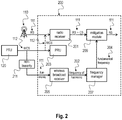
- Fig. 2 is a block diagram 200 of a mobile device 200 with a frequency manager for detecting a fundamental frequency of a wireless charging signal according to the disclosure.
- the mobile device 200 includes a radio receiver 201, a power receiving unit (PRU) 203, a wireless broadcast receiver 205, a frequency manager 207 and a mitigation module 209.
- PRU power receiving unit
- the radio receiver 201 receives a radio signal (RS) 111 from a base station 110, e.g. as described above with respect to Fig. 1 .
- the power receiving unit 203 receives a wireless charging signal (WCS) 121 from a power transmission unit (PTU) 120 which is configured to charge the mobile device 200.
- WCS wireless charging signal
- PTU power transmission unit
- This WCS signal 121 may cause undesired interference 122 with the received radio signal 111 in the radio receiver 201.
- the wireless broadcast receiver 205 receives a harmonic 212 of the wireless charging signal 121 during charging of the mobile device 200.
- the harmonic 212 may be generated by passing the WCS signal 121 through a nonlinearity 211, e.g. a non-linear amplifier.
- the frequency manager 207 scans for a frequency 202 of the harmonic 212 and detects a fundamental frequency 204 of the wireless charging signal 121 based on the scanned harmonic 212.
- the mitigation module 209 mitigates the harmonic content of the wireless charging signal 121 in the received radio signal 111 based on the detected fundamental frequency 204 of the wireless charging signal 121.
- the radio receiver 201 may be a WLAN receiver, a Bluetooth (BT) receiver, a Global Navigation Satellite System (GNSS) receiver, a Frequency modulation radio (FMR) receiver or cellular mobile receiver or any other type of radio receiver.
- BT Bluetooth
- GNSS Global Navigation Satellite System
- FMR Frequency modulation radio
- the power receiving unit 203 may receive the wireless charging signal 121 in an Industrial, Scientific and Medical (ISM) radio frequency band.
- ISM Industrial, Scientific and Medical
- a frequency of the wireless charging signal 121 transmitted by the PTU 120 may lie within a frequency range of about 6.78MHz +/- 15kHz.
- the PTU 120 and the PRU 203 may be designed according to the Alliance for Wireless Power (A4WP) standard.
- the wireless broadcast receiver 205 may be a broadcast radio receiver or a broadcast satellite receiver.
- the broadcast radio receiver may be a Frequency Modulation Radio (FMR) Receiver.
- the frequency manager 207 may scan for a frequency 202 of the harmonic based on country information received by the radio receiver 201.
- the frequency manager 207 may scan for a frequency of a fourteenth or fifteenth harmonic of the wireless charging signal 121 if the country code indicates Japan. Otherwise, if the country code does not indicate Japan, the frequency manager 207 may scan for a frequency of a twelfth harmonic of the wireless charging signal 121.
- FMR Frequency Modulation Radio
- the frequency manager 207 may select a harmonic of a plurality of harmonics of the wireless charging signal 121 received by the broadcast receiver 205 for scanning.
- the frequency manager 207 may perform a received signal strength scan in a frequency range around the selected harmonic with a grid of frequency bins.
- the frequency manager 207 may identify a frequency of a maximum of the scanned received signal strengths as the frequency 202 of the selected harmonic.
- the frequency manager 207 may repeat the received signal strength scan for at least one different harmonic selected from the plurality of harmonics.
- the FMR receiver 205 may include a FM radio frequency tracking loop for locking on a tuned frequency and tracking a position of the tuned frequency relative to a reference crystal frequency of the mobile device 200.
- the frequency manager 207 may tune the FMR receiver 205 on the identified frequency of the selected harmonic.
- the frequency manager 207 may retrieve a channel word of the FM radio frequency tracking loop and may increase a precision of the identified frequency of the selected harmonic based on the retrieved channel word.
- the frequency manager 207 may detect the fundamental frequency 204 of the wireless charging signal 121 based on the identified frequency 202 and a rank of the selected harmonic 212.
- the broadcast radio receiver may be a broadcast satellite receiver, e.g. a Global Navigation Satellite System (GNSS) receiver.
- GNSS Global Navigation Satellite System
- the frequency manager 207 may scan for the 232th harmonic of the wireless charging signal 121.
- the GNSS receiver 205 may include a numerically controlled oscillator (NCO) configured to provide an NCO frequency; a downconverter to downconvert the received signal by the NCO frequency; a scan filter configured to filter the downconverted signal by a lowpass filter around zero frequency; an energy detector configured to detect an energy of the filtered signal; and an integrator configured to integrate the detected energy of the filtered signal to provide an average energy of the received signal.
- NCO numerically controlled oscillator
- the frequency manager 207 may select a harmonic of a plurality of harmonics of the wireless charging signal 121 received by the broadcast receiver 205 for scanning.
- the frequency manager 207 may perform an energy scan in a frequency range around the selected harmonic by successively tuning the NCO frequency on a grid of frequency bins.
- the frequency manager 207 may identify a frequency bin having an average energy corresponding to the selected harmonic of the wireless charging signal.
- a frequency distance of the grid of frequency bins may be smaller than a bandwidth of the lowpass filter.
- the frequency manager 207 may detect the fundamental frequency 204 of the wireless charging signal 121 based on the identified frequency bin and a rank of the selected harmonic.
- Fig. 3 is an exemplary process flow 300 of a method for deriving frequencies of PTU harmonics to apply spurious mitigation according to the disclosure.
- the process flow 300 starts with a first block 301 where an active device is provided, e.g. a mobile device such as a handset or a UE that include a FMR receiver (Rx) and/or a GNSS Rx.
- an active device e.g. a mobile device such as a handset or a UE that include a FMR receiver (Rx) and/or a GNSS Rx.
- a check is performed if A4WP is in power transfer state. If yes, in a third block 303 a check is performed if an FMR receiver is located in the device. If yes, in a fourth block 304 WIFI, BT, cellular, NFC and GNSS modules are turned off and in a fifth block 305 FMR is activated and a scan for PTU harmonics (12 or 15) is performed.
- a sixth block 306 is performed, where WIFI, BT, cellular and NFC modules are turned off. Then in a seventh block 307, a check is performed if the device, e.g. UE, includes a GNSS receiver. If yes, in an eighth block 308, the GNSS receiver is activated and a scan for PTU harmonics, i.e. for the 232th harmonic is performed. In a further block 308a it is described that the scan is performed in 25kHz steps around the 232th harmonic. A histogram chart of received energy is provided. After this scan the process flow continues with the ninth block 309 as described above.
- the technique according to the disclosure is applicable to mobile devices such as handsets and tablets that include a FMR receiver (Rx) and/or a GNSS Rx.
- the technique according to the disclosure consists of using the FMR or GNSS Rx to detect the precise PTU harmonic frequency, calculate the PTU fundamental frequency and store it into volatile memory so it can be used by a high-level entity (HLE) running on the system-on-a-chip (SoC) or application processor (AP).
- HLE high-level entity
- SoC system-on-a-chip
- AP application processor
- the HLE manages the frequencies of internally-generated and externally-injected spurious responses (either narrow or wideband).
- each radio modem on the mobile device can derive the exact frequencies of the PTU harmonics that will affect the active band(s) of operation and use this information to apply spurious-mitigation techniques.
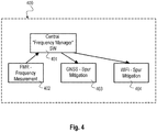
- FIG. 4 A practical implementation of such a process flow 300 is shown in Fig. 4 .
- Fig. 4 is a schematic diagram of a mitigation system 400 according to the disclosure.
- the mitigation system 400 includes one measurement block (e.g. FMR) 402, one management and control block (e.g. Frequency Manager) 401 and one or more mitigation blocks 403, 404 that receive the measured precise frequency as shown in Fig. 4 .
- FMR measurement block
- Management and control block e.g. Frequency Manager
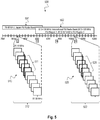
- FMR uses the lowest RF frequency band in a mobile device.
- the 12th harmonic 510 falls in the Japan FMR band 501 as shown in Fig. 5 .
- the 13th harmonic falls both in the International FMR band 502 and the Japan FMR band 501.
- the 14th harmonic falls in the International FMR band 502 and the 15th harmonic 520 also falls in the International FMR band 502.
- the frequency range of each harmonic (with a fundamental accuracy of ⁇ 15kHz) is shown in Fig.
- the wireless charging signal may fall within the parts 511 of the 12 th harmonic 510 and/or the parts 521 of the 15 th harmonic 520.
- the low order of the PTU harmonics ensures that each harmonic power level is high enough to be detected above the input-referred 200kHz bandwidth noise floor yet sufficiently low to prevent any receiver compression or damage.
- the FMR antenna is typically the headset cable (which length is set to resonate at FMR frequencies) but it is not necessary to have this cable plugged in order to detect the PTU harmonics thanks to the particular sensitivity of the FMR receiver to ground signal & noise coupling.
- Fig. 6 is a schematic diagram illustrating a measurement procedure 600 for a single precise measurement of a method for deriving frequencies of PTU harmonics according to the disclosure.
- a suitable harmonic is selected in FMR band, e.g. 12 th or 15 th harmonic.
- the suitable harmonic is denoted as target harmonic 602.
- an RSSI scan is performed around the Nth harmonic providing a maximum power channel 604.
- a tuning to the maximum RSSI channel is performed to provide a PLL word 606.
- a check 607 is performed if a spur is found in 2 out of 3 values. If a spur is found, the final result is reported 608. If no spur is found, the intermediate result is reported 610 and the measurement procedure continues with the first block 601 selecting another suitable harmonic.
- the measurement procedure 600 implements a two-step approach with a Step 1 "RSSI based scan” and a Step 2 "Tune FM radio on spur".
- the two-step approach can be fully implemented on driver level that runs inside the OS (operating system) and to a certain extent even on application level ("FM radio app”) in user space.
- either 101.7 MHz (15th harmonic) can be chosen (if inside Japan) or 81.36 MHz (12th harmonic) can be chosen (if outside of Japan), as these frequencies are not occupied by any commercial radios (see Figure 5 ).
- a second and third measurement on two other harmonics falling into FM radio band can be done, enabling a two out of three decision, if the spur is there or not.
- Step 1 "RSSI based scan"
- a regular FMR band scan is requested that spans ⁇ 300 kHz around the nominal frequency (e.g. 101.7 MHz) with a 50 kHz grid. If there is no FM channel on top of the A4WP spurious harmonic, the maximum RSSI will correspond to the 50 kHz bin which is closest to the spurious harmonic.
- This method can be used down to the sensitivity limit of FM radio, which is always better than - 102 dBm, but typical in the range of -108 dBm to -110 dBm.
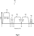
- Step 2 "Tune FM radio on spur", after RSSI scan, the frequency precision is enhanced up to ⁇ 25 kHz, which is in the range of ⁇ 250 ppm. Depending on the to-be-applied mitigation technique (e.g. coherent spur cancellation) much higher precision is required. To achieve this, it is taken advantage of the FM radio inherent feature, that a silent mono FM radio station (no audio, no stereo pilot) is nothing but a single-tone such as the pilot tone 802 depicted in Fig. 8 and therefore not different from an A4WP harmonic. After tuning on the channel with maximum RSSI, the FM radio frequency tracking loop will lock on the harmonic and track its position relative to the reference frequency crystal of the mobile device.
- a silent mono FM radio station no audio, no stereo pilot
- the FM radio frequency tracking loop will lock on the harmonic and track its position relative to the reference frequency crystal of the mobile device.
- the exact frequency can be calculated.
- the default frequency tracking loop settings are already sufficient to get in the single digit ppm range. If further precision is required, the evaluation algorithms can still be optimized, being limited only by the stability of A4WP reference and mobile reference clock.
- the GNSS receiver (which includes a mechanism for detecting jamming signals) can be used as well in case no FMR receiver is present on the mobile device.
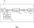
- Fig. 7 is a block diagram of a GNSS jammer detection circuit 700 according to the disclosure.
- the circuit 700 includes a multiplier 701 for multiplying a GNSS IF signal 702 with an output of a numerically controlled oscillator 703 applying 1kHz resolution.
- the output of the multiplier 701 is provided to a narrow low pass filter (LPF) 705, then to a square unit 707 and an energy integrator 709.
- LPF narrow low pass filter
- the circuit 700 shown in Figure 7 can be used as a variable bandwidth (BW) analyzer to detect the existence of the A4WP PTU harmonic in the following manner: a) Turn off WLAN, BT, FMR and Cellular Modem. b) Activate GNSS RF. c) Tune the NCO of the down-converter to 1572.96+3.48MHz to ensure that the lower edge of the scan band is down converted to OHz. d) Set LPF to 50KHz. e) Chart a histogram of the received energy, changing the NCO frequency from 1576.33 to 1569.57 in steps of 25KHz. Note that the Histogram bars will have an overlap of 25% to ensure correct coverage of the full band. f) Monitor for a bin with energy corresponding to A4WP harmonic (typically anything about -120dBm). g) Inform frequency manager of exact frequency of A4WP jammer.
- BW variable bandwidth
- the LPF BW, detection threshold and NCO step can be tuned to reach different levels of sensitivity and accuracy.
- A) Make sure the mobile device battery is nearly depleted (10% energy left for example). The goal is to ensure the mobile device will start harvesting power as soon as placed on a PTU.
- B) Make sure the mobile device is associated with a cellular data network (2G/3G/4G) or WLAN access point. Confirm FMR is enabled. The mobile device is then aware of the country in which it operates and the applicable FMR band over which it can receive FM radio stations.
- C) Place the mobile device on an A4WP charging mat and confirm that wireless power transfer has started (using a H-Field probe for example and observing the 6.78MHz PTU signal on a spectrum analyzer).
- the FMR receiver should scan over the International FM radio band (87.5MHz-108MHz). The mobile device will scan over the Japan band (76-90MHz) however with a particular emphasis on the narrow frequency range of 81.18-81.54MHz (corresponding to the 12th harmonic of the PTU) and the FMR receiver is used as a mean to detect the PTU frequency.
- LO local oscillator
- the disclosed method may be implemented on any mobile device having an FM radio driver or GNSS radio driver.
- Fig. 8 is a frequency diagram illustrating the baseband spectrum of an exemplary FM stereo signal.
- the spectrum illustrates a typical baseband spectrum of an FM receiver used in a mobile device, e.g. a handset or a UE.
- the FM stereo signal is a stereo multiplex signal which is backwards compatible with a large existing base of FM monophonic receivers.
- the 0 to 15 kHz baseband part 801 of the multiplex (MPX) signal includes the left (L) and right (R) channel information (L+R) for monophonic reception.
- Stereophonic sound is achieved by amplitude modulating the (L-R) information onto a suppressed 38 kHz subcarrier in the 23 to 53 kHz region 803, 804 of the baseband spectrum.
- a 19 kHz pilot tone 802 is added to the multiplex signal to enable FM stereo receivers to detect and decode the stereo left 803 and right 804 channels.
- the composite baseband signal format meets the backwards compatibility needed for FM mono receivers while simultaneously providing enough information for FM stereo receivers to decode the left and right stereo channel outputs.
- the MPX signal further includes a 57 kHz subcarrier 805 that carries RDS and RBDS signals.
- the radio frequency tracking loop described in 605 with respect to Fig. 6 is capable to lock on the stereo pilot tone 802 and track its position relative to the reference frequency crystal of the mobile device.
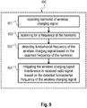
- Fig. 9 is schematic diagram of a method 900 for mitigating a wireless charging interference on a received radio signal in a mobile device.
- the method 900 includes receiving 901 a harmonic of the wireless charging signal by a wireless broadcast receiver of the mobile device during charging of the mobile device, e.g. as described above with respect to the wireless broadcast receiver 205 of Fig. 2 .
- the method 900 includes scanning 902 for a frequency of the harmonic, e.g. as described above with respect to the wireless broadcast receiver 205 of Fig. 2 .
- the method 900 includes detecting 903 a fundamental frequency of the wireless charging signal based on the scanned frequency of the harmonic, e.g. as described above with respect to the frequency manager 207 of Fig. 2 .
- the method 900 includes mitigating 904 the wireless charging signal interference in the received radio signal based on the detected fundamental frequency of the wireless charging signal, e.g. as described above with respect to the mitigation module 209 of Fig. 2 .
- the radio receiver may be a WLAN receiver, a Bluetooth (BT) receiver, a Global Navigation Satellite System (GNSS) receiver, a Frequency modulation radio (FMR) receiver or a cellular mobile receiver or any other radio receiver.
- BT Bluetooth
- GNSS Global Navigation Satellite System
- FMR Frequency modulation radio
- the method 900 may further include receiving the wireless charging signal in an Industrial, Scientific and Medical (ISM) radio frequency band.
- ISM Industrial, Scientific and Medical
- a frequency of the wireless charging signal may for example lie within a frequency range of about 6.78MHz +/-15kHz.
- the wireless charging signal may be according to the Alliance for Wireless Power (A4WP) standard.
- a key advantage of using FMR or GNSS receivers is that no extra HW is required of any sort (e.g. Silicon, RF front end, antenna, power, etc.) but existing radio HW & FW may be reused with their existing specifications.
- any sort e.g. Silicon, RF front end, antenna, power, etc.
- A4WP solution implemented on the handset is a specific device such as a reference design platform, for example, A4WP solution may be in fact a sleeve which integrates the PRU coil, Wireless Power Receiver IC and Bluetooth Low Energy IC. All that is required to trigger the PTU harmonic detection mechanism is an indication that WPT (Wireless Power Transfer) has begun.
- WPT Wireless Power Transfer
- the technique according to the disclosure is a system-level solution that can be extended to other wireless systems containing a frequency measurement block and spur-mitigation mechanisms.
- DSP Digital Signal Processor
- ASIC application specific integrated circuit
- Embodiments described in this disclosure can be implemented in digital electronic circuitry, or in computer hardware, firmware, software, or in combinations thereof, e.g. in available hardware of mobile devices or in new hardware dedicated for processing the methods described herein.
- the present disclosure also supports a computer program product including computer executable code or computer executable instructions that, when executed, causes at least one computer to execute the performing and computing blocks described herein, in particular the methods 300, 600 and 900 as described above with respect to Figs. 3 , 6 and 9 .
- a computer program product may include a readable non-transitory storage medium storing program code thereon for use by a processor, the program code comprising instructions for performing any of the methods 300 and 900 as described above.
Landscapes
- Engineering & Computer Science (AREA)
- Computer Networks & Wireless Communication (AREA)
- Signal Processing (AREA)
- Power Engineering (AREA)
- Circuits Of Receivers In General (AREA)
- Noise Elimination (AREA)
Claims (14)
- Mobilgerät (200), umfassend:einen Funkempfänger (201), ausgelegt zum Empfangen eines Funksignals (111);eine Leistungsempfangseinheit, PRU, (203), ausgelegt zum Empfangen eines drahtlosen Ladesignals (121) von einer Leistungssendeeinheit, PTU, (120), ausgelegt zum Laden des Mobilgeräts;gekennzeichnet durch:einen Drahtlose-Rundsendung-Empfänger (205), ausgelegt zum Empfangen einer Harmonischen (212) des drahtlosen Ladesignals (121) während Ladens des Mobilgeräts (200);einen Frequenzmanager (207), ausgelegt zum Scannen nach einer Frequenz der Harmonischen (212) und zum Detektieren einer Grundfrequenz des drahtlosen Ladesignals (121) auf der Grundlage der gescannten Harmonischen (212); undein Abmilderungsmodul (209), ausgelegt zum Abmildern eines Harmonischeninhalts des drahtlosen Ladesignals (121) in dem empfangenen Funksignal (111) auf der Grundlage der detektierten Grundfrequenz des drahtlosen Ladesignals (121).
- Mobilgerät (200) nach Anspruch 1,
wobei der Funkempfänger (201) ein WLAN-Empfänger oder ein Bluetooth- bzw. BT-Empfänger oder ein Empfänger für ein Globales Navigationssatellitensystem bzw. GNSS-Empfänger oder ein Empfänger für frequenzmodulierten Funk bzw. ein FMR-Empfänger oder ein Empfänger für zellenbasierten Mobilfunk ist. - Mobilgerät (200) nach Anspruch 1 oder 2,
wobei die Leistungsempfangseinheit, PRU, (203) ausgelegt ist zum Empfangen des drahtlosen Ladesignals (121) in einem Funkfrequenzband für Industrie, Wissenschaft und Medizin bzw. einem ISM-Funkfrequenzband. - Mobilgerät (200) nach einem der vorhergehenden Ansprüche,
wobei eine Frequenz des von der PTU (120) gesendeten drahtlosen Ladesignals (121) in einem Frequenzbereich von ungefähr 6,78 MHz ± 15 kHz liegt. - Mobilgerät (200) nach einem der vorhergehenden Ansprüche,
wobei der Drahtlose-Rundsendung-Empfänger (205) ein Rundfunkempfänger oder ein Rundsatellitenempfänger ist. - Mobilgerät (200) nach Anspruch 5,
wobei der Rundfunkempfänger ein Empfänger für frequenzmodulierten Funk bzw. ein FMR-Empfänger ist. - Mobilgerät (200) nach Anspruch 6,
wobei der Frequenzmanager (207) ausgelegt ist zum Scannen nach einer Frequenz der Harmonischen (212) auf der Grundlage von Länderinformationen, die von dem Funkempfänger (201) empfangen werden. - Mobilgerät (200) nach Anspruch 7,
wobei der Frequenzmanager (207) ausgelegt ist zum Scannen nach einer Frequenz einer vierzehnten oder fünfzehnten Harmonischen des drahtlosen Ladesignals (121), falls der Ländercode Japan anzeigt; und
wobei der Frequenzmanager (207) ausgelegt ist zum Scannen nach einer Frequenz einer zwölften Harmonischen des drahtlosen Ladesignals (121), falls der Ländercode nicht Japan anzeigt. - Mobilgerät (200) nach einem der Ansprüche 6 bis 8, wobei der Frequenzmanager (207) ausgelegt ist zum:Auswählen einer Harmonischen aus einer Vielzahl von Harmonischen des drahtlosen Ladesignals (121), das durch den Rundsendeempfänger empfangen wird, zum Scannen;Durchführen eines Empfangssignalstärkescans in einem Frequenzbereich um die ausgewählte Harmonische herum mit einem Raster aus Frequenzfächern; undIdentifizieren einer Frequenz eines Maximums der gescannten Empfangssignalstärken als die Frequenz der ausgewählten Harmonischen.
- Mobilgerät (200) nach Anspruch 9,
wobei der Frequenzmanager (207) ausgelegt ist zum Wiederholen des Empfangssignalstärkescans für mindestens eine andere aus der Vielzahl von Harmonischen ausgewählte Harmonische. - Mobilgerät (200) nach Anspruch 9 oder 10,
wobei der FMR-Empfänger eine FM-Funkfrequenz-Verfolgungsschleife umfasst, welche ausgelegt ist zum Einrasten auf eine Abstimmfrequenz und zum Verfolgen einer Position der Abstimmfrequenz relativ zu einer Quarz-Referenzfrequenz des Mobilgeräts (200). - Verfahren zum Abmildern eines Störeinflusses eines drahtlosen Ladesignals auf ein Funksignal (111), das von einem Funkempfänger (201) eines Mobilgeräts (200) empfangen wird, wobei das Verfahren Folgendes umfasst:Empfangen einer Harmonischen (212) des drahtlosen Ladesignals (121) durch einen Drahtlose-Rundsendung-Empfänger (205) des Mobilgeräts (200) während Ladens des Mobilgeräts (200);gekennzeichnet durch:Scannen nach einer Frequenz der Harmonischen (212);Detektieren einer Grundfrequenz des drahtlosen Ladesignals (121) auf der Grundlage der gescannten Frequenz der Harmonischen (212); undAbmildern des Störeinflusses des drahtlosen Ladesignals in dem empfangenen Funksignal (111) auf der Grundlage der detektierten Grundfrequenz des drahtlosen Ladesignals (121).
- Verfahren nach Anspruch 12,
wobei der Funkempfänger (201) ein WLAN-Empfänger oder ein Bluetooth- bzw. BT-Empfänger oder ein Empfänger für ein Globales Navigationssatellitensystem bzw. GNSS-Empfänger oder ein Empfänger für frequenzmodulierten Funk bzw. ein FMR-Empfänger oder ein Empfänger für zellenbasierten Mobilfunk ist. - Computerlesbares, nicht transitorisches Medium, auf welchem Computeranweisungen gespeichert sind, die, wenn diese durch einen Computer ausgeführt werden, den Computer veranlassen zum Durchführen des Verfahrens nach Anspruch 12 oder 13.
Priority Applications (2)
| Application Number | Priority Date | Filing Date | Title |
|---|---|---|---|
| EP16168749.6A EP3244542B1 (de) | 2016-05-09 | 2016-05-09 | Verfahren und vorrichtung zur interferenzreduzierung in einem drahtlos-ladesignal |
| US15/491,123 US9998238B2 (en) | 2016-05-09 | 2017-04-19 | Method and device for mitigating interference due to a wireless charging signal |
Applications Claiming Priority (1)
| Application Number | Priority Date | Filing Date | Title |
|---|---|---|---|
| EP16168749.6A EP3244542B1 (de) | 2016-05-09 | 2016-05-09 | Verfahren und vorrichtung zur interferenzreduzierung in einem drahtlos-ladesignal |
Publications (2)
| Publication Number | Publication Date |
|---|---|
| EP3244542A1 EP3244542A1 (de) | 2017-11-15 |
| EP3244542B1 true EP3244542B1 (de) | 2019-07-24 |
Family
ID=55963190
Family Applications (1)
| Application Number | Title | Priority Date | Filing Date |
|---|---|---|---|
| EP16168749.6A Active EP3244542B1 (de) | 2016-05-09 | 2016-05-09 | Verfahren und vorrichtung zur interferenzreduzierung in einem drahtlos-ladesignal |
Country Status (2)
| Country | Link |
|---|---|
| US (1) | US9998238B2 (de) |
| EP (1) | EP3244542B1 (de) |
Families Citing this family (13)
| Publication number | Priority date | Publication date | Assignee | Title |
|---|---|---|---|---|
| US10566843B2 (en) * | 2014-07-15 | 2020-02-18 | Qorvo Us, Inc. | Wireless charging circuit |
| US10559970B2 (en) | 2014-09-16 | 2020-02-11 | Qorvo Us, Inc. | Method for wireless charging power control |
| SE541339C2 (en) * | 2014-12-19 | 2019-07-16 | Nok9 Ip Ab | A mobile device tester for precise inductive power measurement and a calibration unit therefor |
| US10673541B2 (en) | 2017-06-02 | 2020-06-02 | Apple Inc. | Methods, systems and apparatus for mitigating wireless connection degradation due to wireless charging |
| KR102001316B1 (ko) * | 2017-11-23 | 2019-10-01 | 고려대학교 산학협력단 | 무선 전력 전송 통신에서 전송 시간 할당 방법 |
| KR102433881B1 (ko) * | 2018-02-14 | 2022-08-19 | 삼성전자주식회사 | 전자 장치 및 그 제어 방법 |
| CN109038850B (zh) * | 2018-06-25 | 2020-07-24 | 华为技术有限公司 | 一种检测无线充电系统中金属异物的装置、设备及方法 |
| CN110108937B (zh) * | 2019-05-10 | 2023-03-14 | 中国电力科学研究院有限公司 | 一种基于谐波分析的无线充电频率选取方法及系统 |
| US10819457B1 (en) * | 2019-07-30 | 2020-10-27 | Motorola Solutions, Inc. | Interference mitigation between cellular and frequency-modulated communication subsystems in a portable communication device |
| US12352871B2 (en) * | 2019-11-27 | 2025-07-08 | Qualcomm Incorporated | Management of concurrent GNSS reception and wireless transmission |
| US11969605B2 (en) | 2020-12-23 | 2024-04-30 | Advanced Neuromodulation Systems, Inc. | Systems and methods for noise filtering in implantable medical device charging systems |
| WO2022140360A1 (en) | 2020-12-23 | 2022-06-30 | Advanced Neuromodulation Systems, Inc. | Systems and methods for noise filtering in implantable medical device charging systems |
| CN112888057B (zh) * | 2021-01-12 | 2023-09-08 | 维沃移动通信有限公司 | Wifi单元的控制方法、装置和电子设备 |
Family Cites Families (9)
| Publication number | Priority date | Publication date | Assignee | Title |
|---|---|---|---|---|
| US8929957B2 (en) * | 2008-11-21 | 2015-01-06 | Qualcomm Incorporated | Reduced jamming between receivers and wireless power transmitters |
| US8582633B2 (en) * | 2010-11-22 | 2013-11-12 | Applied Micro Circuits Corporation | Confirmation of presence of narrowband interference by harmonic analysis |
| US10141770B2 (en) * | 2011-01-18 | 2018-11-27 | Mojo Mobility, Inc. | Powering and/or charging with a plurality of protocols |
| US9161481B2 (en) * | 2012-09-13 | 2015-10-13 | Visteon Global Technologies, Inc. | E-field shield for wireless charger |
| US9455596B2 (en) * | 2012-10-16 | 2016-09-27 | Ford Global Technologies, Llc | System and method for reducing interference between wireless charging and amplitude modulation reception |
| US9065686B2 (en) * | 2012-11-21 | 2015-06-23 | Qualcomm Incorporated | Spur detection, cancellation and tracking in a wireless signal receiver |
| US20150336463A1 (en) * | 2014-05-21 | 2015-11-26 | Delphi Technologies, Inc. | Active electromagnetic interference mitigation system and method |
| US9923584B2 (en) * | 2015-09-03 | 2018-03-20 | Qualcomm Incorporated | Rectifiers for wireless power transfer with impedance inverting filters for reduced electromagnetic interference |
| US9806557B2 (en) * | 2015-09-25 | 2017-10-31 | Intel Corporation | Wireless charging system with adaptive radio frequency interference |
-
2016
- 2016-05-09 EP EP16168749.6A patent/EP3244542B1/de active Active
-
2017
- 2017-04-19 US US15/491,123 patent/US9998238B2/en active Active
Non-Patent Citations (1)
| Title |
|---|
| None * |
Also Published As
| Publication number | Publication date |
|---|---|
| US9998238B2 (en) | 2018-06-12 |
| EP3244542A1 (de) | 2017-11-15 |
| US20170324484A1 (en) | 2017-11-09 |
Similar Documents
| Publication | Publication Date | Title |
|---|---|---|
| EP3244542B1 (de) | Verfahren und vorrichtung zur interferenzreduzierung in einem drahtlos-ladesignal | |
| EP2883405B1 (de) | Vorrichtung und verfahren zur interferenzunterdrückung | |
| US12273825B2 (en) | Configurable radio frequency exposure compliance based on region | |
| US8838046B2 (en) | System and method of hybrid FDM/TDM coexistence interference avoidance | |
| JP5027142B2 (ja) | 干渉を軽減する装置及び方法 | |
| US9674810B2 (en) | Method, apparatus and computer program for search and synchronisation | |
| US12114270B2 (en) | Methods and apparatus for user equipment to differentiate human grip from protective covers | |
| EP3376675A1 (de) | System und verfahren zum koordinieren von mehrfachfunksender-empfängern innerhalb der gleichen vorrichtungsplattform | |
| US9794015B2 (en) | Cell measurements in unlicensed frequency bands | |
| US11382050B2 (en) | Methods and apparatus for user equipment to differentiate human grip from protective covers | |
| EP3264619A1 (de) | Verfahren und vorrichtung zur minderung der interferenz in integrierten sendeempfängern | |
| WO2016195892A1 (en) | Managing specific absorption rate distribution to maximize transmit power of a wireless device | |
| US10033514B2 (en) | Method and apparatus for preventing transmitter leakage | |
| US10555321B2 (en) | Mobile terminal, base station, communication state notification method, and scheduling method | |
| EP3202199B1 (de) | Bestimmung einer mittenfrequenz in einem unlizenzierten frequenzband zur verwendung | |
| US10849002B2 (en) | License assisted access measurement | |
| US9014751B1 (en) | Using signal power levels for coexistence among multiple wireless communication technologies | |
| WO2017105408A1 (en) | Ue categorization and band selection strategy for fractional frequency reuse in full-duplex system | |
| US20140051441A1 (en) | Complex Intermediate Frequency Based Receiver Architecture | |
| US20250344164A1 (en) | Radio frequency exposure compliance using subband transmission power limits | |
| US20250392328A1 (en) | Fast automatic gain control in a wireless receiver | |
| WO2025235446A1 (en) | Radio frequency exposure compliance using subband transmission power limits | |
| EP3081036A1 (de) | Verfahren und mobilstation für basisstationsmessungen | |
| McCarthy | Coexistence of LTE and radar system: Methodology and assessment of radar receivers |
Legal Events
| Date | Code | Title | Description |
|---|---|---|---|
| PUAI | Public reference made under article 153(3) epc to a published international application that has entered the european phase |
Free format text: ORIGINAL CODE: 0009012 |
|
| STAA | Information on the status of an ep patent application or granted ep patent |
Free format text: STATUS: THE APPLICATION HAS BEEN PUBLISHED |
|
| AK | Designated contracting states |
Kind code of ref document: A1 Designated state(s): AL AT BE BG CH CY CZ DE DK EE ES FI FR GB GR HR HU IE IS IT LI LT LU LV MC MK MT NL NO PL PT RO RS SE SI SK SM TR |
|
| AX | Request for extension of the european patent |
Extension state: BA ME |
|
| STAA | Information on the status of an ep patent application or granted ep patent |
Free format text: STATUS: REQUEST FOR EXAMINATION WAS MADE |
|
| 17P | Request for examination filed |
Effective date: 20180711 |
|
| RBV | Designated contracting states (corrected) |
Designated state(s): AL AT BE BG CH CY CZ DE DK EE ES FI FR GB GR HR HU IE IS IT LI LT LU LV MC MK MT NL NO PL PT RO RS SE SI SK SM TR |
|
| GRAP | Despatch of communication of intention to grant a patent |
Free format text: ORIGINAL CODE: EPIDOSNIGR1 |
|
| STAA | Information on the status of an ep patent application or granted ep patent |
Free format text: STATUS: GRANT OF PATENT IS INTENDED |
|
| INTG | Intention to grant announced |
Effective date: 20190222 |
|
| GRAS | Grant fee paid |
Free format text: ORIGINAL CODE: EPIDOSNIGR3 |
|
| GRAA | (expected) grant |
Free format text: ORIGINAL CODE: 0009210 |
|
| STAA | Information on the status of an ep patent application or granted ep patent |
Free format text: STATUS: THE PATENT HAS BEEN GRANTED |
|
| AK | Designated contracting states |
Kind code of ref document: B1 Designated state(s): AL AT BE BG CH CY CZ DE DK EE ES FI FR GB GR HR HU IE IS IT LI LT LU LV MC MK MT NL NO PL PT RO RS SE SI SK SM TR |
|
| REG | Reference to a national code |
Ref country code: GB Ref legal event code: FG4D |
|
| REG | Reference to a national code |
Ref country code: CH Ref legal event code: EP |
|
| REG | Reference to a national code |
Ref country code: DE Ref legal event code: R096 Ref document number: 602016017189 Country of ref document: DE |
|
| REG | Reference to a national code |
Ref country code: AT Ref legal event code: REF Ref document number: 1159431 Country of ref document: AT Kind code of ref document: T Effective date: 20190815 |
|
| REG | Reference to a national code |
Ref country code: IE Ref legal event code: FG4D |
|
| REG | Reference to a national code |
Ref country code: NL Ref legal event code: FP |
|
| REG | Reference to a national code |
Ref country code: LT Ref legal event code: MG4D |
|
| REG | Reference to a national code |
Ref country code: AT Ref legal event code: MK05 Ref document number: 1159431 Country of ref document: AT Kind code of ref document: T Effective date: 20190724 |
|
| PG25 | Lapsed in a contracting state [announced via postgrant information from national office to epo] |
Ref country code: HR Free format text: LAPSE BECAUSE OF FAILURE TO SUBMIT A TRANSLATION OF THE DESCRIPTION OR TO PAY THE FEE WITHIN THE PRESCRIBED TIME-LIMIT Effective date: 20190724 Ref country code: PT Free format text: LAPSE BECAUSE OF FAILURE TO SUBMIT A TRANSLATION OF THE DESCRIPTION OR TO PAY THE FEE WITHIN THE PRESCRIBED TIME-LIMIT Effective date: 20191125 Ref country code: BG Free format text: LAPSE BECAUSE OF FAILURE TO SUBMIT A TRANSLATION OF THE DESCRIPTION OR TO PAY THE FEE WITHIN THE PRESCRIBED TIME-LIMIT Effective date: 20191024 Ref country code: LT Free format text: LAPSE BECAUSE OF FAILURE TO SUBMIT A TRANSLATION OF THE DESCRIPTION OR TO PAY THE FEE WITHIN THE PRESCRIBED TIME-LIMIT Effective date: 20190724 Ref country code: FI Free format text: LAPSE BECAUSE OF FAILURE TO SUBMIT A TRANSLATION OF THE DESCRIPTION OR TO PAY THE FEE WITHIN THE PRESCRIBED TIME-LIMIT Effective date: 20190724 Ref country code: SE Free format text: LAPSE BECAUSE OF FAILURE TO SUBMIT A TRANSLATION OF THE DESCRIPTION OR TO PAY THE FEE WITHIN THE PRESCRIBED TIME-LIMIT Effective date: 20190724 Ref country code: NO Free format text: LAPSE BECAUSE OF FAILURE TO SUBMIT A TRANSLATION OF THE DESCRIPTION OR TO PAY THE FEE WITHIN THE PRESCRIBED TIME-LIMIT Effective date: 20191024 Ref country code: AT Free format text: LAPSE BECAUSE OF FAILURE TO SUBMIT A TRANSLATION OF THE DESCRIPTION OR TO PAY THE FEE WITHIN THE PRESCRIBED TIME-LIMIT Effective date: 20190724 |
|
| PG25 | Lapsed in a contracting state [announced via postgrant information from national office to epo] |
Ref country code: IS Free format text: LAPSE BECAUSE OF FAILURE TO SUBMIT A TRANSLATION OF THE DESCRIPTION OR TO PAY THE FEE WITHIN THE PRESCRIBED TIME-LIMIT Effective date: 20191124 Ref country code: LV Free format text: LAPSE BECAUSE OF FAILURE TO SUBMIT A TRANSLATION OF THE DESCRIPTION OR TO PAY THE FEE WITHIN THE PRESCRIBED TIME-LIMIT Effective date: 20190724 Ref country code: ES Free format text: LAPSE BECAUSE OF FAILURE TO SUBMIT A TRANSLATION OF THE DESCRIPTION OR TO PAY THE FEE WITHIN THE PRESCRIBED TIME-LIMIT Effective date: 20190724 Ref country code: AL Free format text: LAPSE BECAUSE OF FAILURE TO SUBMIT A TRANSLATION OF THE DESCRIPTION OR TO PAY THE FEE WITHIN THE PRESCRIBED TIME-LIMIT Effective date: 20190724 Ref country code: RS Free format text: LAPSE BECAUSE OF FAILURE TO SUBMIT A TRANSLATION OF THE DESCRIPTION OR TO PAY THE FEE WITHIN THE PRESCRIBED TIME-LIMIT Effective date: 20190724 Ref country code: GR Free format text: LAPSE BECAUSE OF FAILURE TO SUBMIT A TRANSLATION OF THE DESCRIPTION OR TO PAY THE FEE WITHIN THE PRESCRIBED TIME-LIMIT Effective date: 20191025 |
|
| PG25 | Lapsed in a contracting state [announced via postgrant information from national office to epo] |
Ref country code: TR Free format text: LAPSE BECAUSE OF FAILURE TO SUBMIT A TRANSLATION OF THE DESCRIPTION OR TO PAY THE FEE WITHIN THE PRESCRIBED TIME-LIMIT Effective date: 20190724 |
|
| PG25 | Lapsed in a contracting state [announced via postgrant information from national office to epo] |
Ref country code: DK Free format text: LAPSE BECAUSE OF FAILURE TO SUBMIT A TRANSLATION OF THE DESCRIPTION OR TO PAY THE FEE WITHIN THE PRESCRIBED TIME-LIMIT Effective date: 20190724 Ref country code: PL Free format text: LAPSE BECAUSE OF FAILURE TO SUBMIT A TRANSLATION OF THE DESCRIPTION OR TO PAY THE FEE WITHIN THE PRESCRIBED TIME-LIMIT Effective date: 20190724 Ref country code: EE Free format text: LAPSE BECAUSE OF FAILURE TO SUBMIT A TRANSLATION OF THE DESCRIPTION OR TO PAY THE FEE WITHIN THE PRESCRIBED TIME-LIMIT Effective date: 20190724 Ref country code: IT Free format text: LAPSE BECAUSE OF FAILURE TO SUBMIT A TRANSLATION OF THE DESCRIPTION OR TO PAY THE FEE WITHIN THE PRESCRIBED TIME-LIMIT Effective date: 20190724 Ref country code: RO Free format text: LAPSE BECAUSE OF FAILURE TO SUBMIT A TRANSLATION OF THE DESCRIPTION OR TO PAY THE FEE WITHIN THE PRESCRIBED TIME-LIMIT Effective date: 20190724 |
|
| PG25 | Lapsed in a contracting state [announced via postgrant information from national office to epo] |
Ref country code: IS Free format text: LAPSE BECAUSE OF FAILURE TO SUBMIT A TRANSLATION OF THE DESCRIPTION OR TO PAY THE FEE WITHIN THE PRESCRIBED TIME-LIMIT Effective date: 20200224 Ref country code: SM Free format text: LAPSE BECAUSE OF FAILURE TO SUBMIT A TRANSLATION OF THE DESCRIPTION OR TO PAY THE FEE WITHIN THE PRESCRIBED TIME-LIMIT Effective date: 20190724 Ref country code: CZ Free format text: LAPSE BECAUSE OF FAILURE TO SUBMIT A TRANSLATION OF THE DESCRIPTION OR TO PAY THE FEE WITHIN THE PRESCRIBED TIME-LIMIT Effective date: 20190724 Ref country code: SK Free format text: LAPSE BECAUSE OF FAILURE TO SUBMIT A TRANSLATION OF THE DESCRIPTION OR TO PAY THE FEE WITHIN THE PRESCRIBED TIME-LIMIT Effective date: 20190724 |
|
| REG | Reference to a national code |
Ref country code: DE Ref legal event code: R097 Ref document number: 602016017189 Country of ref document: DE |
|
| PLBE | No opposition filed within time limit |
Free format text: ORIGINAL CODE: 0009261 |
|
| STAA | Information on the status of an ep patent application or granted ep patent |
Free format text: STATUS: NO OPPOSITION FILED WITHIN TIME LIMIT |
|
| REG | Reference to a national code |
Ref country code: DE Ref legal event code: R082 Ref document number: 602016017189 Country of ref document: DE Representative=s name: BARDEHLE PAGENBERG PARTNERSCHAFT MBB PATENTANW, DE Ref country code: DE Ref legal event code: R081 Ref document number: 602016017189 Country of ref document: DE Owner name: APPLE INC., CUPERTINO, US Free format text: FORMER OWNER: INTEL IP CORPORATION, SANTA CLARA, CALIF., US Ref country code: DE Ref legal event code: R081 Ref document number: 602016017189 Country of ref document: DE Owner name: APPLE INC., CUPERTINO, US Free format text: FORMER OWNER: INTEL IP CORPORATION, SANTA CLARA, CA, US |
|
| PG2D | Information on lapse in contracting state deleted |
Ref country code: IS |
|
| 26N | No opposition filed |
Effective date: 20200603 |
|
| PG25 | Lapsed in a contracting state [announced via postgrant information from national office to epo] |
Ref country code: SI Free format text: LAPSE BECAUSE OF FAILURE TO SUBMIT A TRANSLATION OF THE DESCRIPTION OR TO PAY THE FEE WITHIN THE PRESCRIBED TIME-LIMIT Effective date: 20190724 |
|
| REG | Reference to a national code |
Ref country code: NL Ref legal event code: PD Owner name: APPLE INC.; US Free format text: DETAILS ASSIGNMENT: CHANGE OF OWNER(S), ASSIGNMENT; FORMER OWNER NAME: INTEL IP CORPORATION Effective date: 20200917 |
|
| REG | Reference to a national code |
Ref country code: GB Ref legal event code: 732E Free format text: REGISTERED BETWEEN 20201105 AND 20201111 |
|
| PG25 | Lapsed in a contracting state [announced via postgrant information from national office to epo] |
Ref country code: CH Free format text: LAPSE BECAUSE OF NON-PAYMENT OF DUE FEES Effective date: 20200531 Ref country code: MC Free format text: LAPSE BECAUSE OF FAILURE TO SUBMIT A TRANSLATION OF THE DESCRIPTION OR TO PAY THE FEE WITHIN THE PRESCRIBED TIME-LIMIT Effective date: 20190724 Ref country code: LI Free format text: LAPSE BECAUSE OF NON-PAYMENT OF DUE FEES Effective date: 20200531 |
|
| REG | Reference to a national code |
Ref country code: BE Ref legal event code: MM Effective date: 20200531 |
|
| PG25 | Lapsed in a contracting state [announced via postgrant information from national office to epo] |
Ref country code: LU Free format text: LAPSE BECAUSE OF NON-PAYMENT OF DUE FEES Effective date: 20200509 |
|
| PG25 | Lapsed in a contracting state [announced via postgrant information from national office to epo] |
Ref country code: IE Free format text: LAPSE BECAUSE OF NON-PAYMENT OF DUE FEES Effective date: 20200509 |
|
| PG25 | Lapsed in a contracting state [announced via postgrant information from national office to epo] |
Ref country code: BE Free format text: LAPSE BECAUSE OF NON-PAYMENT OF DUE FEES Effective date: 20200531 |
|
| PG25 | Lapsed in a contracting state [announced via postgrant information from national office to epo] |
Ref country code: MT Free format text: LAPSE BECAUSE OF FAILURE TO SUBMIT A TRANSLATION OF THE DESCRIPTION OR TO PAY THE FEE WITHIN THE PRESCRIBED TIME-LIMIT Effective date: 20190724 Ref country code: CY Free format text: LAPSE BECAUSE OF FAILURE TO SUBMIT A TRANSLATION OF THE DESCRIPTION OR TO PAY THE FEE WITHIN THE PRESCRIBED TIME-LIMIT Effective date: 20190724 |
|
| PG25 | Lapsed in a contracting state [announced via postgrant information from national office to epo] |
Ref country code: MK Free format text: LAPSE BECAUSE OF FAILURE TO SUBMIT A TRANSLATION OF THE DESCRIPTION OR TO PAY THE FEE WITHIN THE PRESCRIBED TIME-LIMIT Effective date: 20190724 |
|
| P01 | Opt-out of the competence of the unified patent court (upc) registered |
Effective date: 20230523 |
|
| PGFP | Annual fee paid to national office [announced via postgrant information from national office to epo] |
Ref country code: NL Payment date: 20250317 Year of fee payment: 10 |
|
| PGFP | Annual fee paid to national office [announced via postgrant information from national office to epo] |
Ref country code: FR Payment date: 20250310 Year of fee payment: 10 |
|
| PGFP | Annual fee paid to national office [announced via postgrant information from national office to epo] |
Ref country code: GB Payment date: 20250320 Year of fee payment: 10 |
|
| PGFP | Annual fee paid to national office [announced via postgrant information from national office to epo] |
Ref country code: DE Payment date: 20250311 Year of fee payment: 10 |